Embed Size (px)
Citation preview
1
�Birmingham, AlabamaNovember 11, 2009
WELCOME TO THEWELCOME TO THEWELCOME TO THEWELCOME TO THE
Cleveland, OH
September 26-27, 2017
1
Process Control for Process Control for Process Control for Process Control for
Electrocoat SystemsElectrocoat SystemsElectrocoat SystemsElectrocoat SystemsJeff Paxon
Axalta Coating Systems
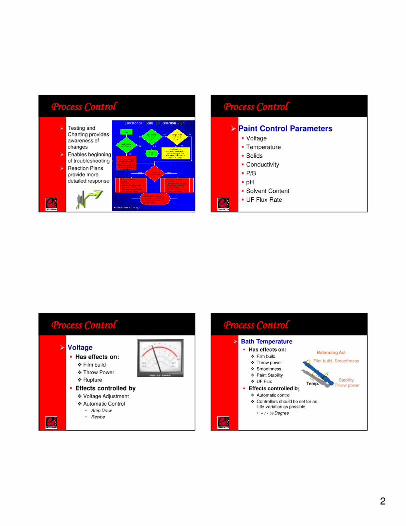
Process ControlProcess ControlProcess ControlProcess Control� Coating characteristics, mainly film build,
change as the operating parameters vary.� Voltage
� Temperature
� pH
� Conductivity
� Solvent Content
� Solids
� P/B
� UF Flux Rate
� Are these parameters monitored and controlled?� Readings recorded
� Charted
� SPC
� Utilize “True” SPC Charts.
� Includes Control Limits and Specifications
� Calculates Process Capability
� Identifies well-controlled processes
� Determines if a process can regularly meet specifications
� Process Capability (CpK) should be greater than or equal to 1.33.
Process ControlProcess ControlProcess ControlProcess Control
Charts are a visual representation of
how well the process is performing.
2
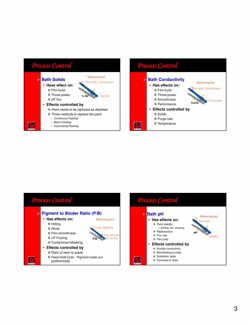
� Testing and Charting provides awareness of changes
� Enables beginning of troubleshooting
� Reaction Plans provide more detailed response
Process ControlProcess ControlProcess ControlProcess Control
� Paint Control Parameters� Voltage
� Temperature
� Solids
� Conductivity
� P/B
� pH
� Solvent Content
� UF Flux Rate
Process ControlProcess ControlProcess ControlProcess Control
� Voltage
� Has effects on:
� Film build
� Throw Power
� Rupture
� Effects controlled by
� Voltage Adjustment
� Automatic Control• Amp Draw
• Recipe
Process ControlProcess ControlProcess ControlProcess Control
� Bath Temperature
� Has effects on:
� Film build
� Throw power
� Smoothness
� Paint Stability
� UF Flux
� Effects controlled by
� Automatic control
� Controllers should be set for as little variation as possible
• + / - ½ Degree
Temp.
Film build, Smoothness
Stability,Throw power
Balancing Act
Process ControlProcess ControlProcess ControlProcess Control
3
� Bath Solids
� Have effect on:
� Film build
� Throw power
� UF flux
� Effects controlled by
� Paint needs to be replaced as depleted
� Three methods to replace the paint
• Continuous Feeding
• Batch Feeding
• Incremental Feeding
% NV
Film build, Throw power
Cost $$
Balancing Act
Process ControlProcess ControlProcess ControlProcess Control
� Bath Conductivity
� Has effects on:
� Film build
� Throw power
� Smoothness
� Performance
� Effects controlled by
� Solids
� Purge rate
� Temperature
Cond.
Film build, Smoothness
Throw power
Balancing Act
Process ControlProcess ControlProcess ControlProcess Control
� Pigment to Binder Ratio (P/B)
� Has effects on:
� Hiding
� Gloss
� Film smoothness
� UF Fouling
� Contaminant Masking
� Effects controlled by
� Ratio of resin to paste
� Feed Hold Outs- Pigment coats out preferentially
P/B
Crater Masking
SmoothnessUF fouling
Balancing Act
Process ControlProcess ControlProcess ControlProcess Control
� Bath pH
� Has effects on:� Paint stability
• Settling, dirt, streaking
� Redissolution
� Flux rate
� Film build
� Effects controlled by� Anolyte conductivity
� Bare/leaking anodes
� Solubilizer adds
� Permeate to drain
pH
Film build
Stability
Balancing Act
Process ControlProcess ControlProcess ControlProcess Control
4
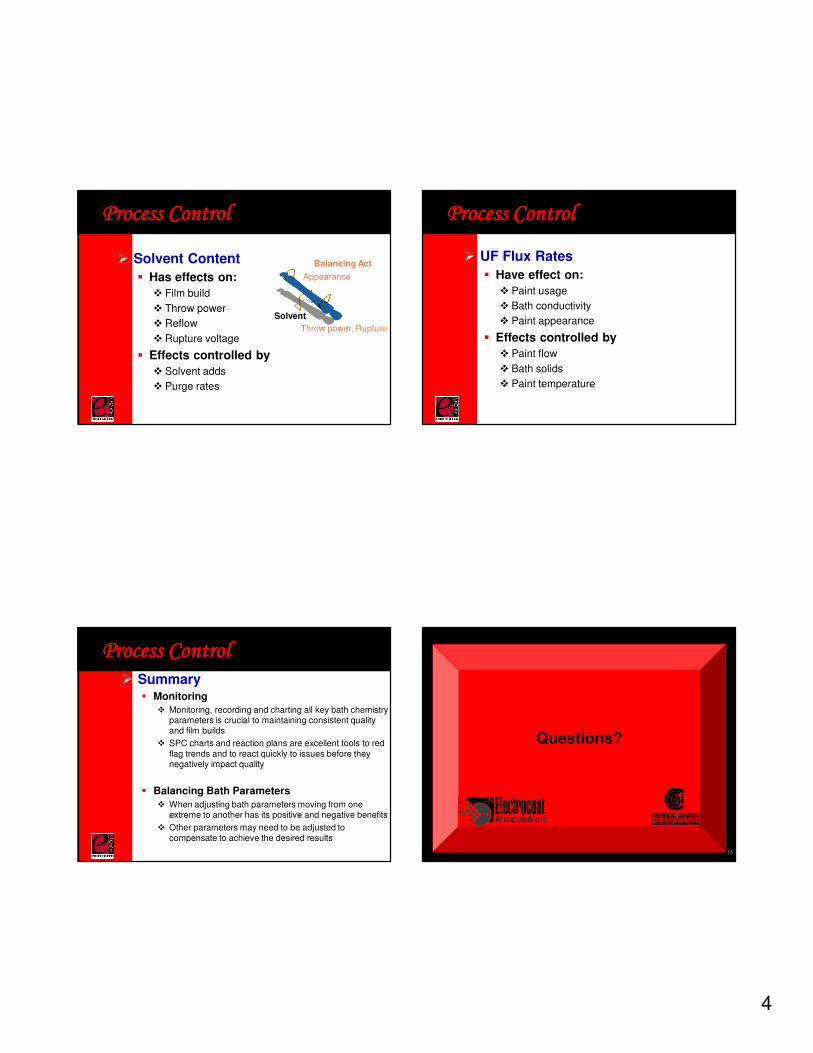
� Solvent Content
� Has effects on:
� Film build
� Throw power
� Reflow
� Rupture voltage
� Effects controlled by
� Solvent adds
� Purge rates
Solvent
Appearance
Throw power, Rupture
Balancing Act
Process ControlProcess ControlProcess ControlProcess Control
� UF Flux Rates
� Have effect on:
� Paint usage
� Bath conductivity
� Paint appearance
� Effects controlled by
� Paint flow
� Bath solids
� Paint temperature
Process ControlProcess ControlProcess ControlProcess Control
� Summary� Monitoring
� Monitoring, recording and charting all key bath chemistry parameters is crucial to maintaining consistent quality and film builds
� SPC charts and reaction plans are excellent tools to red flag trends and to react quickly to issues before they negatively impact quality
� Balancing Bath Parameters
� When adjusting bath parameters moving from one extreme to another has its positive and negative benefits
� Other parameters may need to be adjusted to compensate to achieve the desired results
Process ControlProcess ControlProcess ControlProcess Control
Questions?
16
5
Testing for Testing for Testing for Testing for
ElectrocoatElectrocoatElectrocoatElectrocoat SystemsSystemsSystemsSystemsDavid Miga
BASF Corporation
17
TestsTestsTestsTests
� Standardized laboratory tests that duplicate real-world conditions in order to predict real-world performance
� Three main categories:
� Appearance
� Physical Properties
� Durability
18
� Appearance - How a Coating Looks
� Is the part glossy or flat?
� Is it smooth or rough?
� Does it have any surface defects like dirt or craters?
� How does the color compare to a standard?
TestsTestsTestsTests
19
� Gloss
� Gloss reflects the amount of shine a coating has
� A gloss meter measures the amount of light reflected by the coating surface and is quantified by % of light reflected.
� It is typically measured at angles of 20°, 60°, & 85°.
TestsTestsTestsTests
20
6
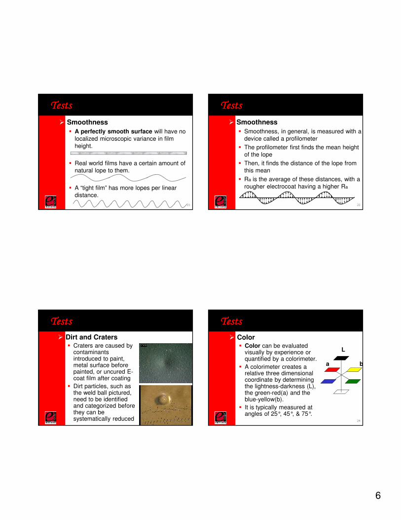
� Smoothness
� A perfectly smooth surface will have no localized microscopic variance in film height.
� Real world films have a certain amount of natural lope to them.
� A “tight film” has more lopes per linear distance.
TestsTestsTestsTests
21
� Smoothness
� Smoothness, in general, is measured with a device called a profilometer
� The profilometer first finds the mean height of the lope
� Then, it finds the distance of the lope from this mean
� Ra is the average of these distances, with a rougher electrocoat having a higher Ra
TestsTestsTestsTests
22
� Dirt and Craters� Craters are caused by
contaminants introduced to paint, metal surface before painted, or uncured E-coat film after coating
� Dirt particles, such as the weld ball pictured, need to be identified and categorized before they can be systematically reduced
TestsTestsTestsTests
23
� Color� Color can be evaluated
visually by experience or quantified by a colorimeter.
� A colorimeter creates a relative three dimensional coordinate by determining the lightness-darkness (L), the green-red(a) and the blue-yellow(b).
� It is typically measured at angles of 25°, 45°, & 75°.
TestsTestsTestsTests
L
a b
24
7
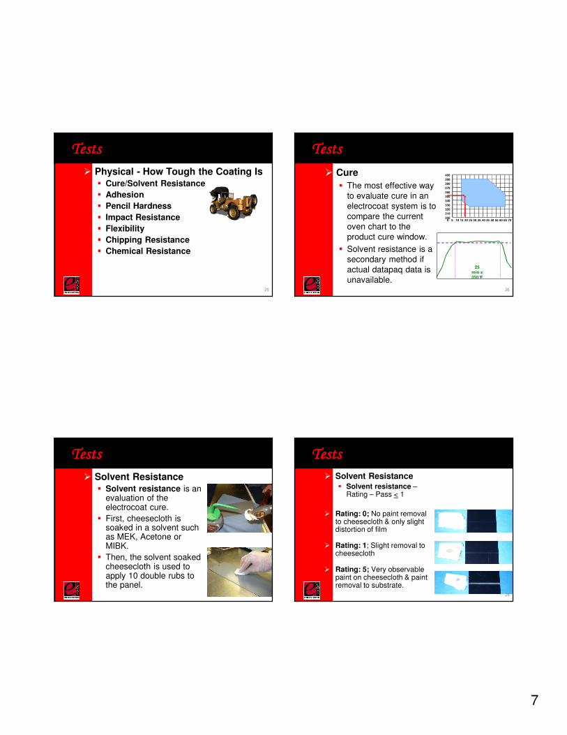
� Physical - How Tough the Coating Is� Cure/Solvent Resistance
� Adhesion
� Pencil Hardness
� Impact Resistance
� Flexibility
� Chipping Resistance
� Chemical Resistance
TestsTestsTestsTests
25
� Cure
� The most effective way to evaluate cure in an electrocoat system is to compare the current oven chart to the product cure window.
� Solvent resistance is a secondary method if actual datapaq data is unavailable.
TestsTestsTestsTests
300
310
320
330
340
350
360
370
380
390
400
0 5 10 15 20 25 30 35 40 45 50 55 60 65 70
25 min x 350°F
26
� Solvent Resistance� Solvent resistance is an
evaluation of the electrocoat cure.
� First, cheesecloth is soaked in a solvent such as MEK, Acetone or MIBK.
� Then, the solvent soaked cheesecloth is used to apply 10 double rubs to the panel.
TestsTestsTestsTests
27
� Solvent Resistance� Solvent resistance –
Rating – Pass < 1
� Rating: 0; No paint removal to cheesecloth & only slight distortion of film
� Rating: 1; Slight removal to cheesecloth
� Rating: 5; Very observable paint on cheesecloth & paint removal to substrate.
TestsTestsTestsTests
28
8
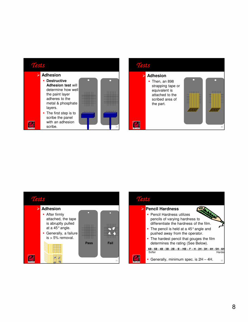
� Adhesion
� Destructive Adhesion test will determine how well the paint layer adheres to the metal & phosphate layers.
� The first step is to scribe the panel with an adhesion scribe.
TestsTestsTestsTests
29
� Adhesion
� Then, an 898 strapping tape or equivalent is attached to the scribed area of the part.
TestsTestsTestsTests
30
� Adhesion
� After firmly attached, the tape is abruptly pulled at a 45°angle.
� Generally, a failure is > 5% removal.
TestsTestsTestsTests
Pass Fail
31
� Pencil Hardness
� Pencil Hardness utilizespencils of varying hardness to differentiate the hardness of the film.
� The pencil is held at a 45°angle and pushed away from the operator.
� The hardest pencil that gouges the film determines the rating (See Below).
� Generally, minimum spec. is 2H – 4H.
TestsTestsTestsTests
6B - 5B - 4B - 3B - 2B – B – HB – F – H - 2H - 3H - 4H - 5H - 6HSofter Harder
32
9
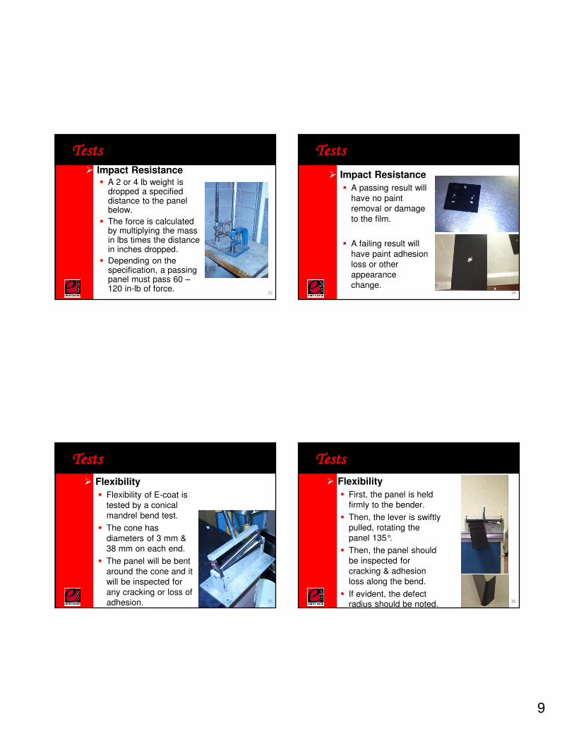
� Impact Resistance� A 2 or 4 lb weight is
dropped a specified distance to the panel below.
� The force is calculated by multiplying the mass in lbs times the distance in inches dropped.
� Depending on the specification, a passing panel must pass 60 –120 in-lb of force.
TestsTestsTestsTests
33
� Impact Resistance
� A passing result will have no paint removal or damage to the film.
� A failing result will have paint adhesion loss or other appearance change.
TestsTestsTestsTests
34
� Flexibility
� Flexibility of E-coat is tested by a conical mandrel bend test.
� The cone has diameters of 3 mm & 38 mm on each end.
� The panel will be bent around the cone and it will be inspected for any cracking or loss of adhesion.
TestsTestsTestsTests
35
� Flexibility
� First, the panel is held firmly to the bender.
� Then, the lever is swiftly pulled, rotating the panel 135°.
� Then, the panel should be inspected for cracking & adhesion loss along the bend.
� If evident, the defect radius should be noted.
TestsTestsTestsTests
36
10
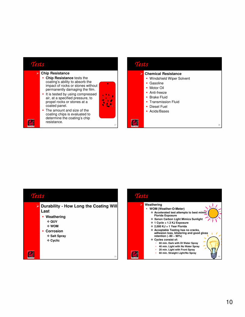
� Chip Resistance
� Chip Resistance tests the coating’s ability to absorb the impact of rocks or stones without permanently damaging the film.
� It is tested by using compressed air, at a specified pressure, to propel rocks or stones at a coated panel.
� The amount and size of the coating chips is evaluated to determine the coating’s chip resistance.
TestsTestsTestsTests
37
� Chemical Resistance
� Windshield Wiper Solvent
� Gasoline
� Motor Oil
� Anti-freeze
� Brake Fluid
� Transmission Fluid
� Diesel Fuel
� Acids/Bases
TestsTestsTestsTests
38
� Durability - How Long the Coating Will Last
� Weathering
� QUV
� WOM
� Corrosion
� Salt Spray
� Cyclic
TestsTestsTestsTests
39
� Weathering
� WOM (Weather-O-Meter)� Accelerated test attempts to best mimic
Florida Exposure
� Xenon Carbon Light Mimics Sunlight
� 1 Cycle = 1.3 KJ Exposure
� 2,000 KJ = 1 Year Florida
� Acceptable Testing has no cracks, adhesion loss, blistering and good gloss retention (~80 – 90%)
� Cycles consist of:
• 60 min. Dark with DI Water Spray
• 40 min. Light with No Water Spray
• 20 min. Light with Front Spray
• 60 min. Straight Light/No Spray
TestsTestsTestsTests
40
11
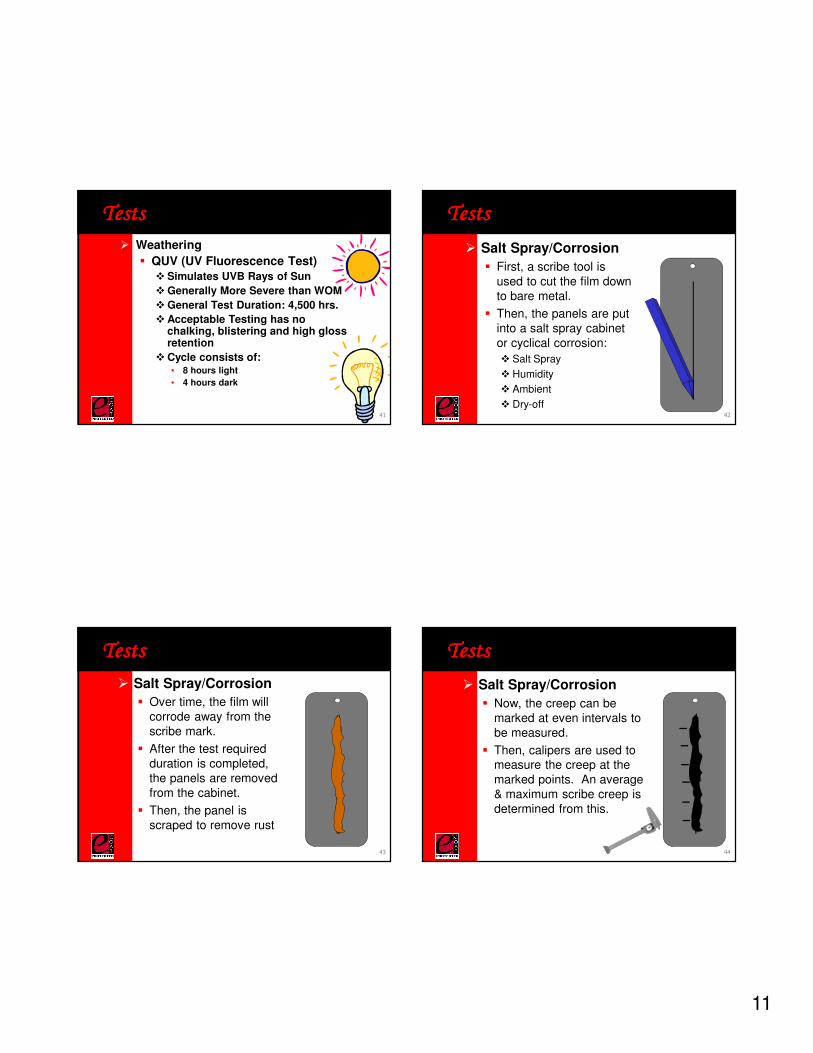
� Weathering
� QUV (UV Fluorescence Test)� Simulates UVB Rays of Sun
� Generally More Severe than WOM
� General Test Duration: 4,500 hrs.
� Acceptable Testing has no chalking, blistering and high gloss retention
� Cycle consists of:• 8 hours light
• 4 hours dark
TestsTestsTestsTests
41
� Salt Spray/Corrosion
� First, a scribe tool is used to cut the film down to bare metal.
� Then, the panels are put into a salt spray cabinet or cyclical corrosion:
� Salt Spray
� Humidity
� Ambient
� Dry-off
TestsTestsTestsTests
42
� Salt Spray/Corrosion
� Over time, the film will corrode away from the scribe mark.
� After the test required duration is completed, the panels are removed from the cabinet.
� Then, the panel is scraped to remove rust
TestsTestsTestsTests
43
TestsTestsTestsTests
� Salt Spray/Corrosion
� Now, the creep can be marked at even intervals to be measured.
� Then, calipers are used to measure the creep at the marked points. An average & maximum scribe creep is determined from this.
44
12
Questions?Questions?Questions?Questions?
45
Refreshment BreakRefreshment BreakRefreshment BreakRefreshment Break
46
Preventative Maintenance Preventative Maintenance Preventative Maintenance Preventative Maintenance
for for for for ElectrocoatElectrocoatElectrocoatElectrocoat SystemsSystemsSystemsSystemsJonathan Quick
BASF Corporation
47
� General Maintenance
� Circulation System
� Anolyte System
� UF System
� Bacteria
� E-coat Oven
Preventive MaintenancePreventive MaintenancePreventive MaintenancePreventive Maintenance
48
13
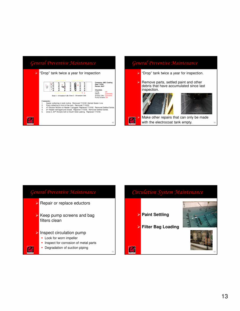
� “Drop” tank twice a year for inspection
General Preventive Maintenance
Zone 1 – 14 Anolyte Cells Zone 2 – 24 Anolyte Cells
Comments:
1. Sealer collecting in tank incline. Removed 7/10/02. Alerted Sealer Line.2. Parts collecting in front of the tank. Removed 7/10/02.3. 4th Eductor Nozzle on Header 3 plugged. Replaced 7/10/02. Removed Settled Solids.4. 5th Header damaged and closed. Repaired 7/10/02. Removed Settled Solids.5. Zone 2, 22nd Anolyte Cell on South Side Leaking. Replaced 7/10/02.
Company: ABC CoatingDate: 7/9/02Person: MJT
Checklist:Lining OKDebris CommentsAnolyte Cells CommentsPump Screens OK
12
3
5
4
49
� “Drop” tank twice a year for inspection.
� Remove parts, settled paint and other debris that have accumulated since last inspection.
General Preventive Maintenance
� Make other repairs that can only be made
with the electrocoat tank empty. 50
� Repair or replace eductors
� Keep pump screens and bag filters clean
� Inspect circulation pump� Look for worn impeller
� Inspect for corrosion of metal parts
� Degradation of suction piping
General Preventive Maintenance
51
� Paint Settling
� Filter Bag Loading
Circulation System Maintenance
52
14
Circulation System Maintenance
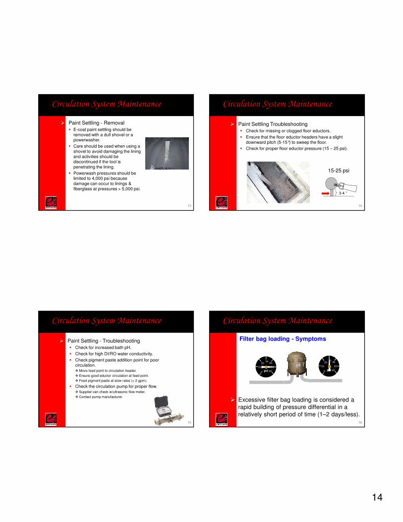
� Paint Settling - Removal� E-coat paint settling should be
removed with a dull shovel or a powerwasher.
� Care should be used when using a shovel to avoid damaging the lining and activities should be discontinued if the tool is penetrating the lining.
� Powerwash pressures should be limited to 4,000 psi because damage can occur to linings & fiberglass at pressures > 5,000 psi.
53
Circulation System Maintenance
� Paint Settling Troubleshooting� Check for missing or clogged floor eductors.
� Ensure that the floor eductor headers have a slight downward pitch (5-15°) to sweep the floor.
� Check for proper floor eductor pressure (15 – 25 psi).
3-4 ”
15-25 psi
54
Circulation System Maintenance
� Paint Settling - Troubleshooting� Check for increased bath pH.
� Check for high DI/RO water conductivity.
� Check pigment paste addition point for poor circulation.� Move feed point to circulation header.
� Ensure good eductor circulation at feed point.
� Feed pigment paste at slow rates (< 2 gpm).
� Check the circulation pump for proper flow.� Supplier can check w/ultrasonic flow meter.
� Contact pump manufacturer.
55
Circulation System Maintenance
Filter bag loading - Symptoms
� Excessive filter bag loading is considered a rapid building of pressure differential in a relatively short period of time (1–2 days/less).
psi0
20
4060
80
100
120 psi0
20
4060
80
100
120psi0
10
2030
40
50
60 psi0
10
2030
40
50
60psi0
10
2030
40
50
60psi0
10
2030
40
50
60
56
15
Circulation System Maintenance
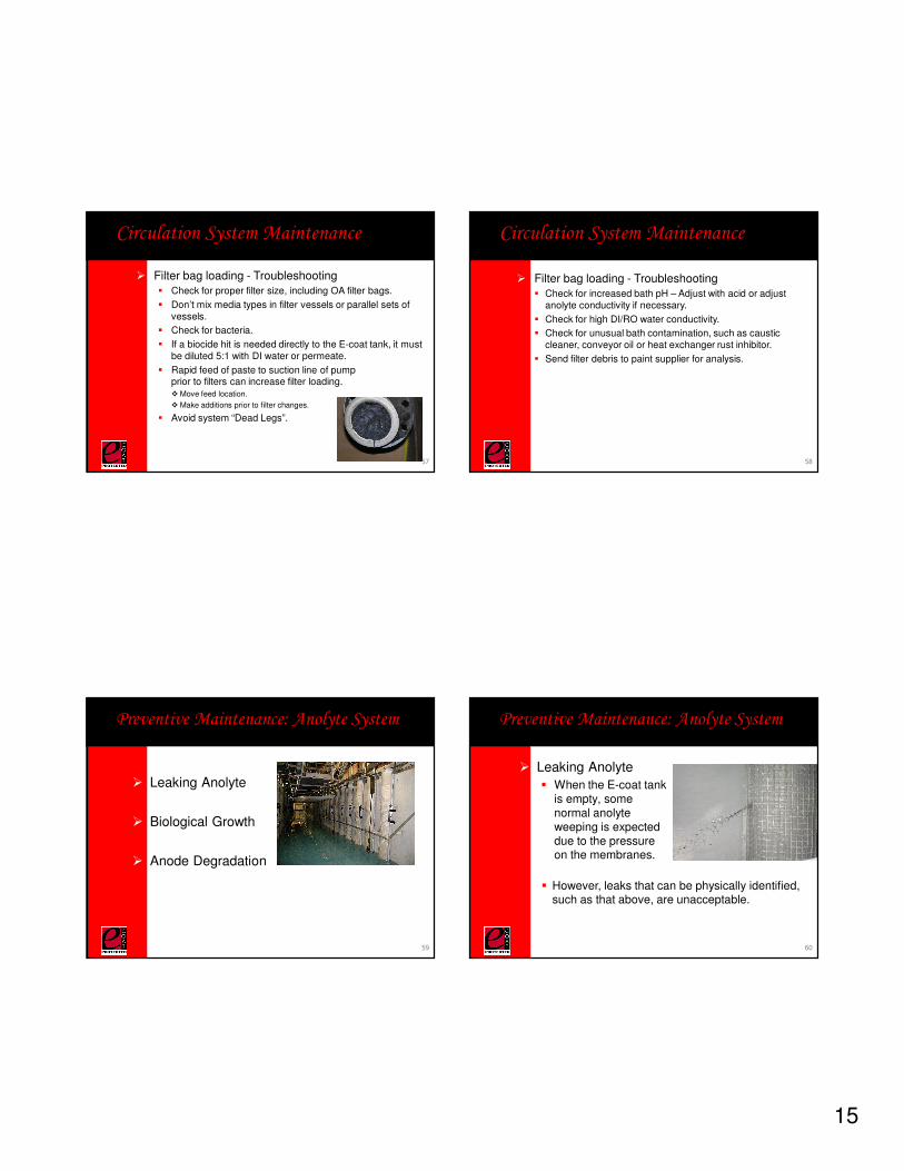
� Filter bag loading - Troubleshooting� Check for proper filter size, including OA filter bags.
� Don’t mix media types in filter vessels or parallel sets of vessels.
� Check for bacteria.
� If a biocide hit is needed directly to the E-coat tank, it must be diluted 5:1 with DI water or permeate.
� Rapid feed of paste to suction line of pump prior to filters can increase filter loading.� Move feed location.
� Make additions prior to filter changes.
� Avoid system “Dead Legs”.
57
Circulation System Maintenance
� Filter bag loading - Troubleshooting� Check for increased bath pH – Adjust with acid or adjust
anolyte conductivity if necessary.
� Check for high DI/RO water conductivity.
� Check for unusual bath contamination, such as caustic cleaner, conveyor oil or heat exchanger rust inhibitor.
� Send filter debris to paint supplier for analysis.
58
� Leaking Anolyte
� Biological Growth
� Anode Degradation
Preventive Maintenance: Anolyte System
59
� Leaking Anolyte
� When the E-coat tank is empty, some normal anolyteweeping is expected due to the pressure on the membranes.
Preventive Maintenance: Anolyte System
� However, leaks that can be physically identified, such as that above, are unacceptable.
60
16
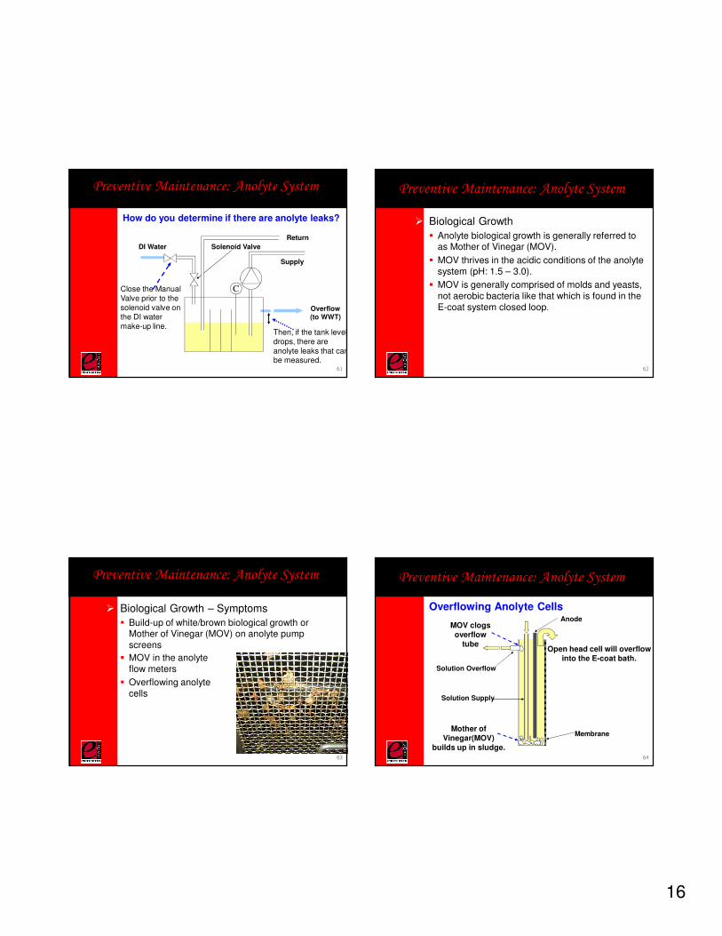
How do you determine if there are anolyte leaks?
DI Water
Overflow(to WWT)
Solenoid Valve
Close the Manual Valve prior to the solenoid valve on the DI water make-up line.
Return
C
Supply
Then, if the tank level drops, there are anolyte leaks that can be measured.
Preventive Maintenance: Anolyte System
61
� Biological Growth
� Anolyte biological growth is generally referred to as Mother of Vinegar (MOV).
� MOV thrives in the acidic conditions of the anolyte system (pH: 1.5 – 3.0).
� MOV is generally comprised of molds and yeasts, not aerobic bacteria like that which is found in the E-coat system closed loop.
Preventive Maintenance: Anolyte System
62
� Biological Growth – Symptoms
� Build-up of white/brown biological growth or Mother of Vinegar (MOV) on anolyte pump screens
� MOV in the anolyte flow meters
� Overflowing anolyte cells
Preventive Maintenance: Anolyte System
63
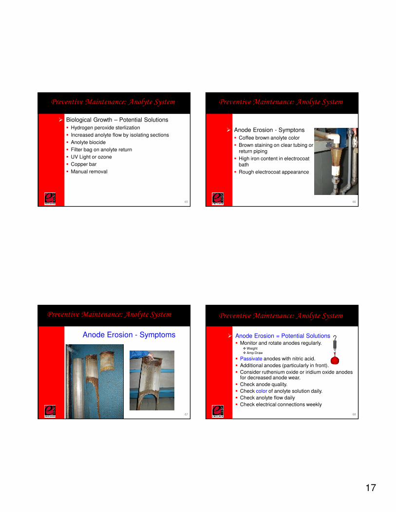
Preventive Maintenance: Anolyte System
Membrane
Overflowing Anolyte CellsAnode
Solution Overflow
Solution Supply
Mother of Vinegar(MOV)
builds up in sludge.
MOV clogsoverflow
tubeOpen head cell will overflow
into the E-coat bath.
64
17
� Biological Growth – Potential Solutions
� Hydrogen peroxide sterlization
� Increased anolyte flow by isolating sections
� Anolyte biocide
� Filter bag on anolyte return
� UV Light or ozone
� Copper bar
� Manual removal
Preventive Maintenance: Anolyte System
65
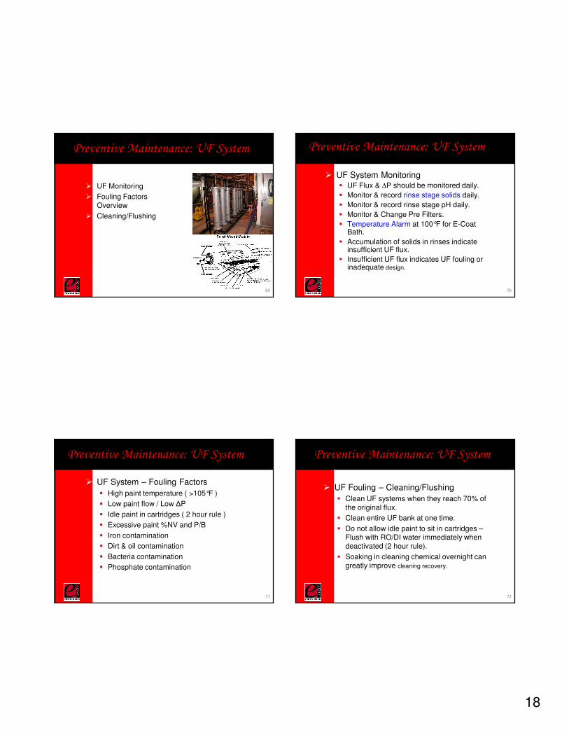
� Anode Erosion - Symptons
� Coffee brown anolyte color
� Brown staining on clear tubing or return piping
� High iron content in electrocoat bath
� Rough electrocoat appearance
Preventive Maintenance: Anolyte System
66
Anode Erosion - Symptoms
Preventive Maintenance: Anolyte System
67
Preventive Maintenance: Anolyte System
� Anode Erosion = Potential Solutions� Monitor and rotate anodes regularly.
� Weight
� Amp Draw
� Passivate anodes with nitric acid.
� Additional anodes (particularly in front).
� Consider ruthenium oxide or iridium oxide anodes for decreased anode wear.
� Check anode quality.
� Check color of anolyte solution daily.
� Check anolyte flow daily
� Check electrical connections weekly
68
18
� UF Monitoring
� Fouling Factors Overview
� Cleaning/Flushing
Preventive Maintenance: UF System
69
� UF System Monitoring� UF Flux & ∆P should be monitored daily.
� Monitor & record rinse stage solids daily.
� Monitor & record rinse stage pH daily.
� Monitor & Change Pre Filters.
� Temperature Alarm at 100°F for E-Coat Bath.
� Accumulation of solids in rinses indicate insufficient UF flux.
� Insufficient UF flux indicates UF fouling or inadequate design.
Preventive Maintenance: UF System
70
� UF System – Fouling Factors
� High paint temperature ( >105°F )
� Low paint flow / Low ΔP
� Idle paint in cartridges ( 2 hour rule )
� Excessive paint %NV and P/B
� Iron contamination
� Dirt & oil contamination
� Bacteria contamination
� Phosphate contamination
Preventive Maintenance: UF System
71
� UF Fouling – Cleaning/Flushing
� Clean UF systems when they reach 70% of the original flux.
� Clean entire UF bank at one time.
� Do not allow idle paint to sit in cartridges –Flush with RO/DI water immediately when deactivated (2 hour rule).
� Soaking in cleaning chemical overnight can greatly improve cleaning recovery.
Preventive Maintenance: UF System
72
19
� UF Fouling – Cleaning/Flushing
� Utilize special cleaning chemicals for special contaminants, including:
� Normal Fouling/Metal Fines:UF Cleaner
� Iron Contamination: UF Cleaner & Citric Acid
� Bacteria Contamination: UF Cleaner & Biocide
� Phosphate Drag-In: UF Cleaner & Nitric Acid
� Oil Contamination: UF Cleaner & OA Filters
Preventive Maintenance: UF System
73
� What are its symptoms?
� How can it be eliminated?
Preventive Maintenance: Bacteria
74
� Field easy culture testing
� Dip slides
� External laboratory testing
� Bacteria enzyme activity detection
Preventive Maintenance: Bacteria
There are a few options to consider in identifying the presence of bacteria by testing:
75
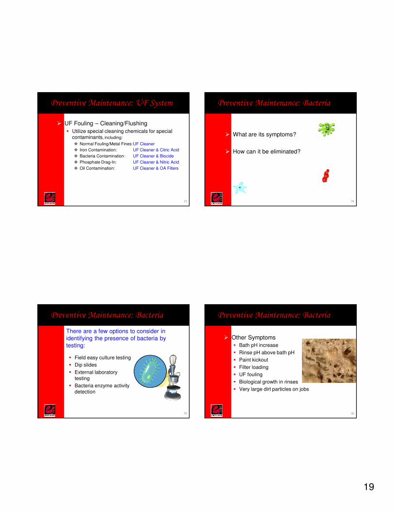
� Other Symptoms
� Bath pH increase
� Rinse pH above bath pH
� Paint kickout
� Filter loading
� UF fouling
� Biological growth in rinses
� Very large dirt particles on jobs
Preventive Maintenance: Bacteria
76
20
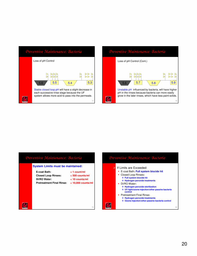
Loss of pH Control
Preventive Maintenance: Bacteria
5.5 5.4 5.35.6
Stable closed loop pH will have a slight decrease in each successive rinse stage because the UF system allows more acid to pass into the permeate.
77
Loss of pH Control (Cont.)
Preventive Maintenance: Bacteria
Unstable pH, influenced by bacteria, will have higher pH in the rinses because bacteria can more easily grow in the later rinses, which have less paint solids.
5.7 5.8 5.95.6
78
� E-coat Bath: < 1 count/ml
� Closed Loop Rinses: < 500 counts/ml
� DI/RO Water: < 10 counts/ml
� Pretreatment Final Rinse: < 10,000 counts/ml
Preventive Maintenance: Bacteria
System Limits must be maintained:
79
� If Limits are Exceeded:� E-coat Bath: Full system biocide hit
� Closed Loop Rinses: � Full system biocide hit
� Hydrogen peroxide treatments
� DI/RO Water: � Hydrogen peroxide sterilization
� UV light/ozone injection/other passive bacteria control
� Pretreatment Final Rinse: � Hydrogen peroxide treatments
� Ozone injection/other passive bacteria control
Preventive Maintenance: Bacteria
80
21
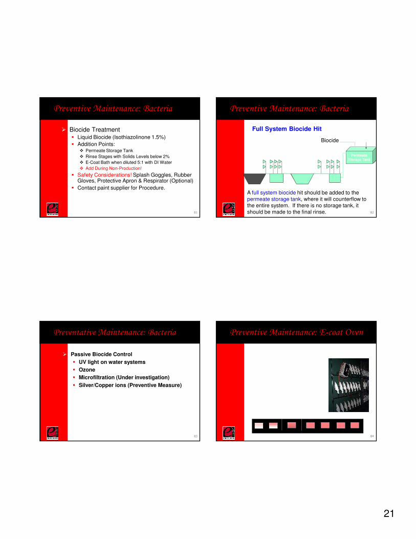
� Biocide Treatment� Liquid Biocide (Isothiazolinone 1.5%)
� Addition Points:� Permeate Storage Tank
� Rinse Stages with Solids Levels below 2%
� E-Coat Bath when diluted 5:1 with DI Water
� Add During Non-Production!
� Safety Considerations! Splash Goggles, Rubber Gloves, Protective Apron & Respirator (Optional)
� Contact paint supplier for Procedure.
Preventive Maintenance: Bacteria
81
Full System Biocide Hit
Preventive Maintenance: Bacteria
A full system biocide hit should be added to thepermeate storage tank, where it will counterflow to the entire system. If there is no storage tank, it should be made to the final rinse.
PermeateStorage Tank
VirginPermeateBiocide
PermeateStorage Tank
82
� Passive Biocide Control
� UV light on water systems
� Ozone
� Microfiltration (Under investigation)
� Silver/Copper ions (Preventive Measure)
Preventative Maintenance: Bacteria
83
Preventive Maintenance: E-coat Oven
84
22
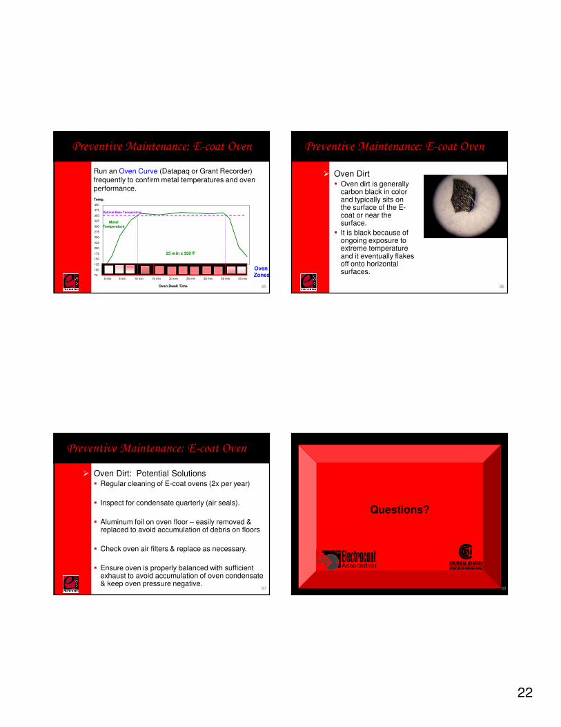
Run an Oven Curve (Datapaq or Grant Recorder) frequently to confirm metal temperatures and oven performance.
25 min x 350°F
400
375
350
325
300
275
250
225
200
175
150
125
100
750 min 5 min 10 min 15 min 20 min 25 min 30 min 35 min 40 min
Metal Temperature
Optimal Bake Temperature
10 min Ramp
Oven Dwell Time
Temp.
Oven Zones
Preventive Maintenance: E-coat Oven
85
� Oven Dirt� Oven dirt is generally
carbon black in color and typically sits on the surface of the E-coat or near the surface.
� It is black because of ongoing exposure to extreme temperature and it eventually flakes off onto horizontal surfaces.
Preventive Maintenance: E-coat Oven
86
� Oven Dirt: Potential Solutions� Regular cleaning of E-coat ovens (2x per year)
� Inspect for condensate quarterly (air seals).
� Aluminum foil on oven floor – easily removed & replaced to avoid accumulation of debris on floors
� Check oven air filters & replace as necessary.
� Ensure oven is properly balanced with sufficient exhaust to avoid accumulation of oven condensate & keep oven pressure negative.
Preventive Maintenance: E-coat Oven
87
Questions?
88
23
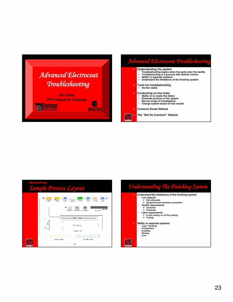
Advanced Electrocoat Advanced Electrocoat Advanced Electrocoat Advanced Electrocoat
TroubleshootingTroubleshootingTroubleshootingTroubleshooting
Jim Gezo
PPG Industrial Coatings
Advanced Electrocoat TroubleshootingAdvanced Electrocoat TroubleshootingAdvanced Electrocoat TroubleshootingAdvanced Electrocoat Troubleshooting
� Understanding the system� Troubleshooting begins when the parts enter the facility� Troubleshooting is a process with defined criteria� Ability to separate systems� Understand the limitations of the finishing system
� Tools for troubleshooting� On-line needs
� Conducting on-line trials� Ability to re-create the defect� Eliminate portions of the system� Narrow scope of investigation� Change system based on test results
� Common Ecoat Defects
� The “Not So Common” Defects
Electrocoat Process:Electrocoat Process:Electrocoat Process:Electrocoat Process:
Sample Process LayoutSample Process LayoutSample Process LayoutSample Process Layout
91
Oven
Sample Tank
Stages• Cleaning• Pretreatment• Rinsing• E-Coat• Permeate Rinsing• DI Rinsing
Racking
Flash (Pre-bake)
Power Supply / Process Control
Understanding The Finishing SystemUnderstanding The Finishing SystemUnderstanding The Finishing SystemUnderstanding The Finishing System
� Understand the limitations of the finishing system• Line capacity
� Part silhouette� Equipment and chemistry constraints
• Quality requirements� Customer� Corporate
• Labor requirements� In line racking vs. off line racking� Tooling
� Ability to separate systems• Load / Handling• Pretreatment• Ecoating• Rinsing• Cure
24
Understanding The Finishing SystemUnderstanding The Finishing SystemUnderstanding The Finishing SystemUnderstanding The Finishing System
� Troubleshooting is a process with well defined criteria
• Time bound – It has a beginning and an end
• Specific
� Troubleshooting begins when the parts enter the facility
• Containers
• Bins
• Packing materials
� Troubleshooting ends
• Change must occur
• Document and communicate
Tools for TroubleshootingTools for TroubleshootingTools for TroubleshootingTools for Troubleshooting
� Safety
• Review
� SOP, Lock-Out-Tag-Out
� MSDS
� Documentation of supplier’s materials
� Common Sense
� Define
• Documentation
� Defect numbers ($$)
� Trials
� Metrics – definition of success
� Track success
Tools for TroubleshootingTools for TroubleshootingTools for TroubleshootingTools for Troubleshooting
� Tooling
• Ability to change hang pattern / orientation
• Line metal / most common substrate
• Laboratory phosphate
� Access to off-line equipment
• Rinsing
• Curing
• Coating� Typically provided by supplier
� Feed material for control bath
Conducting OnConducting OnConducting OnConducting On----line Trialsline Trialsline Trialsline Trials� Ability to re-create the defect
• Identify changes made to create defect
• Something changed within the system
• Something must change to correct
� Eliminate portions of the system• Laboratory phosphated vs. line phosphated
• Skip stages
• Rotate parts after phosphate / ecoat tank / post rinses
� Narrow scope of investigation• Once a portion of the system eliminated
• Repeatability
� Change system based on test results• Monitor for success
• Document and share results
25
Common Ecoat DefectsCommon Ecoat DefectsCommon Ecoat DefectsCommon Ecoat Defects
� Contamination
• Dirt
• Ionic
• Metals
� Craters
� Rupture
Dirt / StabilityDirt / StabilityDirt / StabilityDirt / Stability
� Poor appearance
� Kick-out
� Paint sludging
� Poor horizontal settle
� Filter bags fouling
� Loss in flux rate/Ultrafilter fouling
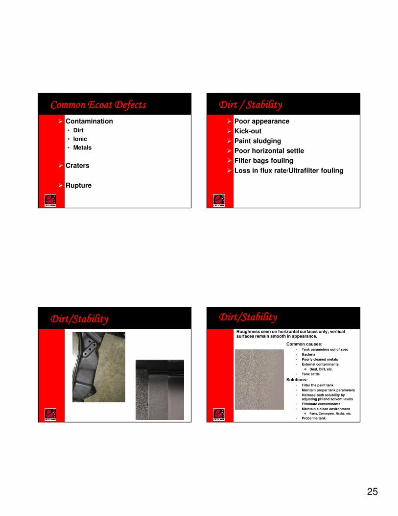
Dirt/StabilityDirt/StabilityDirt/StabilityDirt/Stability Dirt/StabilityDirt/StabilityDirt/StabilityDirt/Stability
Common causes:• Tank parameters out of spec
• Bacteria
• Poorly cleaned metals
• External contaminants
� Dust, Dirt, etc.
• Tank settle
Solutions:• Filter the paint tank
• Maintain proper tank parameters
• Increase bath solubility by adjusting pH and solvent levels
• Eliminate contaminants
• Maintain a clean environment
� Parts, Conveyors, Racks, etc.
• Probe the tank
Roughness seen on horizontal surfaces only; vertical surfaces remain smooth in appearance.
26
Ionic ContaminationIonic ContaminationIonic ContaminationIonic Contamination
� Poor appearance
� Patchy roughness
� Rupture
� High conductivity
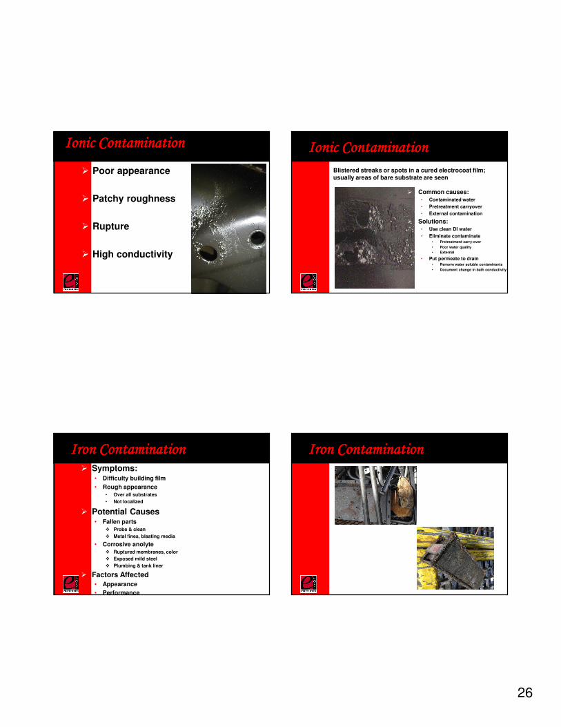
Ionic ContaminationIonic ContaminationIonic ContaminationIonic Contamination
� Common causes:• Contaminated water
• Pretreatment carryover
• External contamination
� Solutions:• Use clean DI water
• Eliminate contaminate• Pretreatment carry-over
• Poor water quality
• External
• Put permeate to drain• Remove water soluble contaminants
• Document change in bath conductivity
Blistered streaks or spots in a cured electrocoat film; usually areas of bare substrate are seen
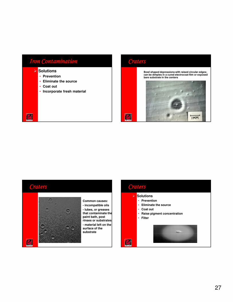
Iron ContaminationIron ContaminationIron ContaminationIron Contamination� Symptoms:
• Difficulty building film
• Rough appearance• Over all substrates
• Not localized
� Potential Causes• Fallen parts
� Probe & clean
� Metal fines, blasting media
• Corrosive anolyte� Ruptured membranes, color
� Exposed mild steel
� Plumbing & tank liner
� Factors Affected
• Appearance
• Performance
Iron ContaminationIron ContaminationIron ContaminationIron Contamination
27
Iron ContaminationIron ContaminationIron ContaminationIron Contamination
� Solutions
• Prevention
• Eliminate the source
• Coat out
• Incorporate fresh material
CratersCratersCratersCraters
� Bowl shaped depressions with raised circular edges; can be dimples in a cured electrocoat film or exposed bare substrate in the centers
CratersCratersCratersCraters
� Common causes:
� - incompatible oils
� - lubes, or greases that contaminate the paint bath, post rinses or substrates
� - material left on the surface of the substrate
CratersCratersCratersCraters
� Solutions
• Prevention
• Eliminate the source
• Coat out
• Raise pigment concentration
• Filter
28
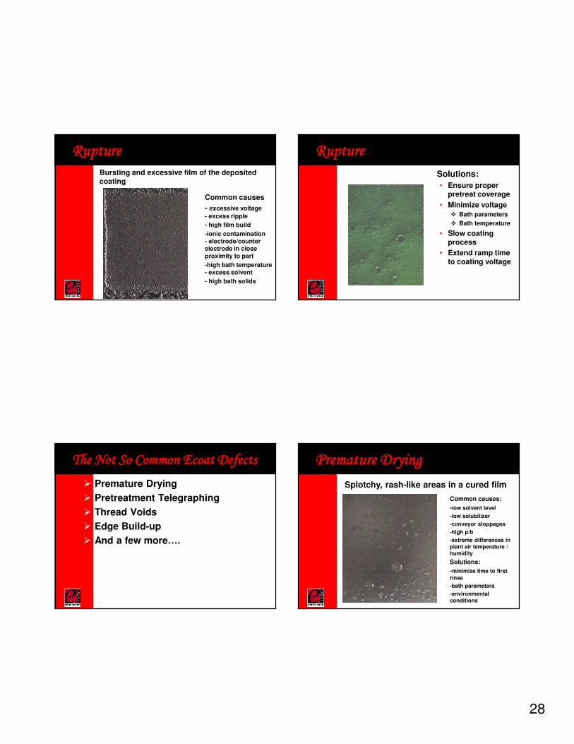
RuptureRuptureRuptureRupture
� Common causes
� - excessive voltage
- excess ripple
� - high film build
� -ionic contamination - electrode/counter electrode in close proximity to part
� -high bath temperature - excess solvent
� - high bath solids
Bursting and excessive film of the deposited coating
RuptureRuptureRuptureRupture
� Solutions:
• Ensure proper pretreat coverage
• Minimize voltage
� Bath parameters
� Bath temperature
• Slow coating process
• Extend ramp time to coating voltage
The Not So Common Ecoat DefectsThe Not So Common Ecoat DefectsThe Not So Common Ecoat DefectsThe Not So Common Ecoat Defects
� Premature Drying
� Pretreatment Telegraphing
� Thread Voids
� Edge Build-up
� And a few more….
Premature DryingPremature DryingPremature DryingPremature Drying
� Common causes:
• -low solvent level
• -low solubilizer
• -conveyor stoppages
• -high p/b
• -extreme differences in plant air temperature / humidity
� Solutions:
� -minimize time to first
rinse
� -bath parameters
� -environmental conditions
Splotchy, rash-like areas in a cured film
29
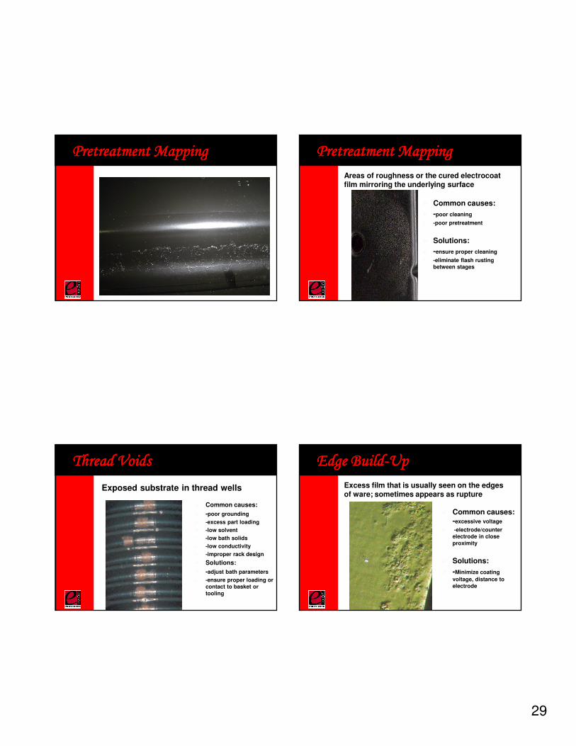
Pretreatment MappingPretreatment MappingPretreatment MappingPretreatment Mapping Pretreatment MappingPretreatment MappingPretreatment MappingPretreatment Mapping
� Common causes:
� -poor cleaning
� -poor pretreatment
� Solutions:
� -ensure proper cleaning
� -eliminate flash rusting between stages
Areas of roughness or the cured electrocoat film mirroring the underlying surface
Thread VoidsThread VoidsThread VoidsThread Voids
� Common causes:
� -poor grounding
� -excess part loading
� -low solvent
� -low bath solids
� -low conductivity
� -improper rack design
� Solutions:
� -adjust bath parameters
� -ensure proper loading or contact to basket or tooling
Exposed substrate in thread wells
Edge BuildEdge BuildEdge BuildEdge Build----UpUpUpUp
� Common causes: -excessive voltage
� -electrode/counter electrode in close proximity
� Solutions:
� -Minimize coating
voltage, distance to electrode
Excess film that is usually seen on the edges of ware; sometimes appears as rupture
30
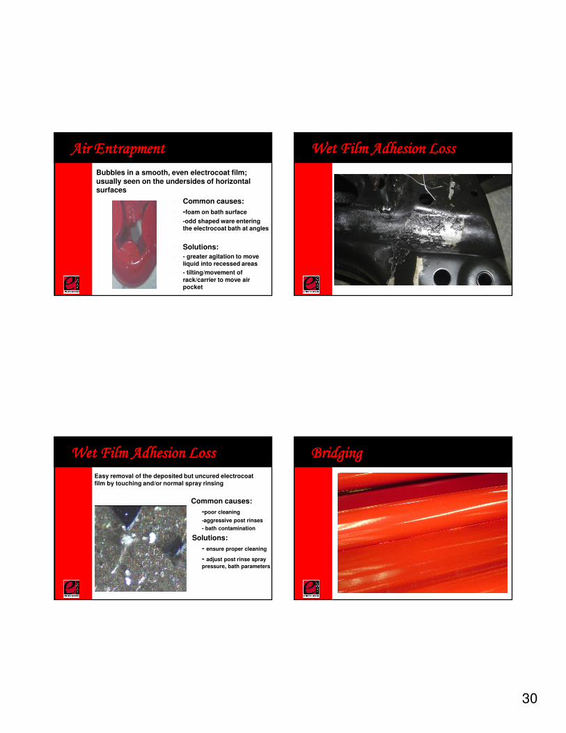
Air EntrapmentAir EntrapmentAir EntrapmentAir Entrapment
� Common causes:
� -foam on bath surface
� -odd shaped ware entering the electrocoat bath at angles
� Solutions:
� - greater agitation to move liquid into recessed areas
� - tilting/movement of rack/carrier to move air pocket
Bubbles in a smooth, even electrocoat film; usually seen on the undersides of horizontal surfaces
Wet Film Adhesion LossWet Film Adhesion LossWet Film Adhesion LossWet Film Adhesion Loss
Wet Film Adhesion LossWet Film Adhesion LossWet Film Adhesion LossWet Film Adhesion Loss
� Common causes:
-poor cleaning
-aggressive post rinses
- bath contamination
Solutions:
- ensure proper cleaning
- adjust post rinse spray
pressure, bath parameters
Easy removal of the deposited but uncured electrocoat film by touching and/or normal spray rinsing
BridgingBridgingBridgingBridging
31
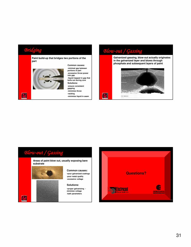
BridgingBridgingBridgingBridging
� Common causes:
� -minimal gap between portions of part
� -excessive throw power into gap
� -liquid trapped in gap that boils out during cure
� Solutions:
� -ensure consistent gapping
� -minimize throw
� -racking
� -minimize liquid in seam
Paint build-up that bridges two portions of the part
BlowBlowBlowBlow----out / Gassingout / Gassingout / Gassingout / GassingGalvanized gassing, blow-out actually originates in the galvanized layer and blows through phosphate and subsequent layers of paint
BlowBlowBlowBlow----out / Gassingout / Gassingout / Gassingout / Gassing
� Common causes: -poor galvanized coatings
� -poor metal quality
� -excessive voltage
� Solutions:
� -proper galvanizing -
minimize voltage
� -bath parameters
Areas of paint blow out, usually exposing bare substrate
Questions?
124
32
Group LunchGroup LunchGroup LunchGroup Lunch
125
Panel DiscussionPanel DiscussionPanel DiscussionPanel Discussion
126
Thank you for joining us and have a safe trip
home after the
PPG Coating Services –MetoKote Corporation
Plant Tour!
Electrocoating Seminar
127