Embed Size (px)
Citation preview
Clinical and laboratory proceduresCement-retained restorations

Welcome to the world of Astra Tech DentalOur goal is to provide you with The freedom of unlimited possibilities™ when it comes to
implant therapy. We develop products and solutions to help make your job as simple as
possible but we never compromise on reliable long-term function and esthetics.
The Astra Tech Implant System™ is developed with a biological and biomechanical
approach. Every detail is carefully designed to fit together and work in harmony with
each other and with nature. The excellent long-term results of our implant system have
been proven in numerous clinical studies.
To support you in the use of The Astra Tech Implant System, we offer education seminars,
training programs and materials for you and all members of your treatment team.
This manual provides a step-by-step overview for cement-retained restorations.

ContentsClinical and laboratory procedures for cement-retained restorations utilizing the Astra Tech Implant System™.
Restorative overview 4
Abutment overview 5
Considerations and implant overview 6
Abutment selection 7
Try-in abutments 8
Temporary restoration
Healing Abutment 9
TempDesign™ 10
Temporary Abutment 10
Implant-level impression 13
Permanent implant restoration
Atlantis™ Abutments 17
Direct Abutment™ 20
TiDesign™ 25
ZirDesign™ 28
CastDesign™ 32
Torque guide 36
Cleaning and sterilization procedures 37
References 38
This manual is designed for use by dental professionals who have undergone at least basic prosthetic and in-clinic implant training. Staying current on the latest trends and treatment techniques in implant dentistry through continued education is the responsibility of the clinician.
3

RESTORATIvE OvERvIEW
• Atlantis™ Abutments• Direct Abutment™
• TiDesign™
• ZirDesign™
• CastDesign™
• CastDesign™
Single
Partial
• Cresco™
• UniAbutment• Angled Abutment
• Atlantis™ Abutments• Direct Abutment™
• TiDesign™
• ZirDesign™
• CastDesign™
• Cresco™
• UniAbutment• Angled Abutment
• Atlantis™ Abutments• Direct Abutment™
• TiDesign™
• CastDesign™
Cement-retained
Screw-retained
Screw-retained
Screw-retained
Full Splinted• UniAbutment• Cresco™
Attachment-retained
Non-splinted• Locator™ Abutment• Ball Abutment
Cement-retained
Cement-retained
4

ABUTmenT OVeRVIeW
Abutments designed for implant-level impression Indications and intended use Features and benefits Page
Atlantis™ Abutments – titaniumAtlantis™ Abutments – GoldHue™ Atlantis™ Abutments – zirconia, white and shaded
• Single, partial and fully edentulous situations
• All positions in the mouth
• Patient-specific abutment uniquely designed from the final tooth shape
• Available for all major implant systems
17
TiDesign™ Titanium
• Single, partial and fully edentulous situations
• All positions in the mouth
• Pre-designed and for easy customization
• Straight and angled versions available
25
ZirDesign™ Zirconia
• Single and partial edentulous situations
• Anterior, canine and premolar
• Pre-designed and for easy customization
• Straight and angled versions available
28
CastDesign™
Base: non oxidizing gold alloyCylinder: PmmA burnout plastic
• Single, partial and fully edentulous situations
• All positions in the mouth• Cement-retained single crown and
bridge restorations• One-piece screw-retained single
restoration
• Abutment for laboratory customization
• Compensation for up to 30° angulation
32
Abutments designed for abutment-level impression Indications and intended use Features and benefits
Direct Abutment™Titanium
• Single, partial and fully edentulous situations
• All positions in the mouth
• Handling just like conventional crown and bridge technique
• API™ (All Parts Included) kit available for both clinical and laboratory procedures
20
Abutments for Temporization Indications and intended use Features and benefits
TempDesign™ Base: Titanium Cylinder: PeeK plastic
• Single, partial and fully edentulous situations
• All positions in the mouth• Cement- and screw-retained
temporary restorations
• Simplifies chairside temporization• Biocompatible tooth-colored
material
10
Temporary AbutmentTitanium
• Single, partial and fully edentulous situations
• All positions in the mouth• Cement- and screw-retained
temporary restorations
• Ideal for long-term temporization 10
Laboratory Abutment ScrewAvoid usage and wear of the clinical screw and ensure that an uncompromized screw is used in the clinical situation by using the Laboratory Abutment Screw for laboratory procedures.
5
Oss
eoSp
eed™
TX
Impl
ant 3.0 S 3.5 S 4.0 S 4.5 5.0 5.0 S
Indi
catio
ns
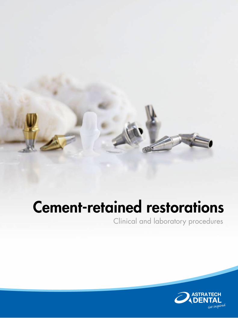
For replacement of maxillary laterals and mandibular central and lateral incisors when there is not enough space for a wider implant.
In all positions in the jaws.
Single tooth to full arch.
In all positions in the jaws.
Single tooth to full arch.
In all positions in the jaws.
Single tooth to full arch.
In all positions in the jaws.
Single tooth to full arch.
In all positions in the jaws. Especially indicat-ed for wide ridges and large edentulous spaces and for increased stabil-ity in extraction sockets when doing immediate implant installation
Single tooth to full arch.
Not
e
It is recommended that when possible, a wider implant is used.
For single-standing, non- splinted restorations in the molar regions, the use of a wider implant is recommended.
OsseoSpeed™ TX Implant 4.0 S – 6 mm should only be used when there is not enough space for a longer implant. Immediate loading of single tooth restorations is not recommended.
3.0 mm
1.7 mm
3.5 mm
1.9 mm
4.0 mm
2.4 mm
4.5 mm
1.9 mm
5.0 mm
2.4 mm
5.0 mm
3.2 mm
COnSIDeRATIOnS AnD ImPLAnT OVeRVIeW
Implant overviewThe OsseoSpeed™ TX implants have been developed and extensively documented for both one- and two-stage surgical procedures. All Astra Tech implants are designed to allow for indexing. The Conical Seal Design™ of the Astra Tech Implant System™ allows for a strong and stable implant-abutment connection.
Intended use• In replacing missing teeth in single or multiple unit applications within the mandible or maxilla• Indicated for immediate placement in extraction sites and partially or completely healed alveolar ridge
situations• especially indicated for use in soft bone applications where implants with other implant surface
treatments may be less effective• Suitable for immediate loading* in all indications, except in single tooth situations in soft bone (type IV)
where implant stability may be difficult to obtain and immediate loading may not be appropriate * Immediate loading of single-tooth restorations with OsseoSpeed™ TX Implant 4.0 S – 6 mm is not recommended.
It is important that the clinician takes loading conditions into consideration when determining the number and spacing of short implants. Considering the reduced bone support provided by short implants, it is important for the purpose of early diagnosis and treatment that the clinician closely monitor soft tissue and supporting bone health status by means of probing and radiographic evaluation when indicated.
From a mechanical strength point of view it is recommended to always place as wide an implant as possible. This is particularly important in the posterior regions of the jaws where loading forces are high and considerable bending moments could be generated.
6

Abutment selectionAstra Tech Implant System™ includes a wide range of abutments designed to successfully meet all implant indications. In addition to simply supporting the crown, the abutments are designed to:
• minimize the risk for overload and fractures by transferring forces to the implant
• establish and maintain healthy connective tissue and epithelial attachment• Resolve dimensional and geometric discrepancies between the crown and
implant
Factors to consider when choosing an abutment: • Single tooth, partial or full fixed bridge• Type of restoration• Implant-level or abutment-level impression• Anterior or posterior region• esthetic demands• Implant angulations• Tissue conditions• Occlusal interproximal space• Adjacent teeth and roots
Measuring systemThe measuring system is straightforward and easy to use. All measurements are indicated in millimeters and the starting point is always at the implant-level starting at 0 mm.
A complete range of screwdrivers and instruments needed for the prosthetic procedures are available.
ABUTmenT SeLeCTIOn
7

Model planningSelect the appropriate abutment for clinical use by using try-in abutments with the Implant Replica.
ABUTmenT SeLeCTIOnTry-in abutments
Clinical planningUse the try-in abutments to select the most appropriate abutment for clinical use.
Note: When using try-in abutments in a clinical situation, it is recommended that the abutments are secured (e.g. with dental floss) as a precautionary measure.
Try-in abutments are reusable after proper cleaning and sterilization.
Try-in abutmentsTry-in abutments are available for TiDesign™*/ZirDesign™ abutments and Direct Abutment™. They help to simplify appropriate abutment selection and restorative planning for both the clinician and the dental technician.
For easy identification, try-in abutments are color-coded and marked with size and height. Try-in components are designed to seat into implants and implant replicas with a friction fit.
*Not available for 3.0 S (X-Small connection; yellow)
Indications and intended use• For appropriate abutment selection• Simplifies planning for the restoration
8

Healing AbutmentHealing Abutment is a solid, one-piece component, designed to support optimal esthetic results. The abutment is used for soft tissue contouring during the healing phase and can be used for both one- and two-stage surgery.
Healing Abutments can be used in combination with removable temporization.
One-stage surgeryPlace a Healing Abutment at time of implant installation. After healing, replace the healing abutment with a temporary or permanent abutment.
Two-stage surgery Place a Cover Screw at time of implant installation and suture the soft tissue. After appropriate healing period the healing abutment is placed at a second surgical procedure. From here on continue as for One-stage surgery.
Indications and intended use• All positions in the mouth• For intermediate use only
TemPORARy ReSTORATIOnHealing Abutment
marked with lines to identify connection size. 3.0 – marked with 1 line3.5/4.0 – marked with 2 lines4.5/5.0 – marked with 3 lines
Install the Healing Abutment with the Hex Screwdriver using light finger force.
Recommended torque: manual manual manual
9

TemPORARy ReSTORATIOnTempDesign™ /Temporary Abutment
TempDesign™/Temporary AbutmentTempDesign™ and Temporary Abutments are two-piece components that function as customized bases for temporary, implant-level constructions. By using one of these abutments, the soft tissue can be sculptured for an esthetic final result.
TempDesign can be easily customized chairside by the clinician or in the laboratory by the dental technician. In most cases, the Temporary Abutment is customized by the dental technician. In order to support optimal soft tissue sculpturing and avoid unnecessary interference with biological processes, the customized design of these abutments should be as close to the final restoration as possible.
Indications and intended use• Single, partial and fully edentulous situations• All positions in the mouth• Cement- and screw-retained restorations
10
TemPORARy ReSTORATIOnTempDesign™
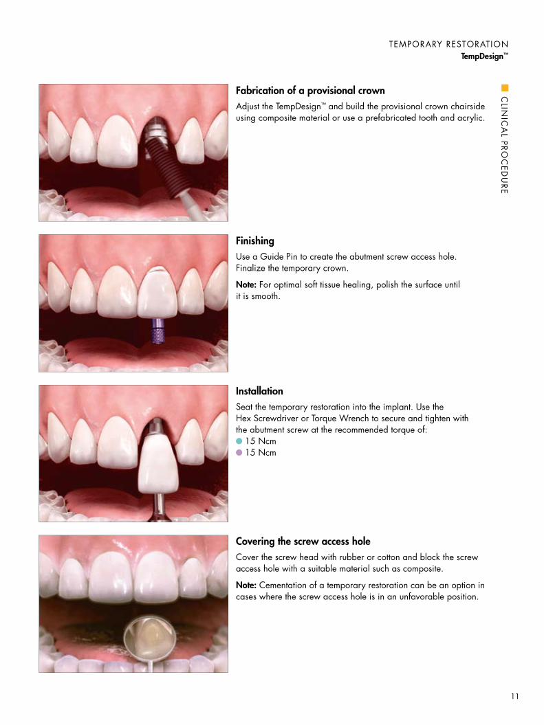
Fabrication of a provisional crown Adjust the TempDesign™ and build the provisional crown chairside using composite material or use a prefabricated tooth and acrylic.
FinishingUse a Guide Pin to create the abutment screw access hole. Finalize the temporary crown.
Note: For optimal soft tissue healing, polish the surface until it is smooth.
InstallationSeat the temporary restoration into the implant. Use the Hex Screwdriver or Torque Wrench to secure and tighten with the abutment screw at the recommended torque of:
15 Ncm 15 Ncm
Covering the screw access holeCover the screw head with rubber or cotton and block the screw access hole with a suitable material such as composite.
Note: Cementation of a temporary restoration can be an option in cases where the screw access hole is in an unfavorable position.
CLIn
ICA
L PROC
eDU
Re
11

TemPORARy ReSTORATIOnTemporary Abutment
FinishingGrind, polish and finalize the temporary restoration.
Note: Use a Laboratory Abutment Screw when fabricating the temporary restoration. Replace with a clinical abutment screw for placement of the temporary abutment in the clinical situation.
FabricationCover the Temporary Abutment with opaque material. Build up with composite or attach the prefabricated tooth and fill with acrylic material.
Use a Guide Pin to create the abutment screw access hole.
Abutment planningPlace the Temporary Abutment in the model using a Laboratory Abutment Screw and Hex Screwdriver. Check the orientation and occlusal clearance.
mark the abutment where modifications are needed.
ModificationUsing a Laboratory Abutment Screw, seat the abutment into an Implant Replica and mount it in a Grinding Handle for easy handling. modify the Temporary Abutment as needed for the clinical situation.
Note: make sure not to damage the conical part of the abutment during modification.
Recommended torque: 15 Ncm 15 Ncm 15 Ncm
LAB
OR
ATO
Ry P
RO
Ce
DU
Re
12
ImPLAnT-LeVeL ImPReSSIOn
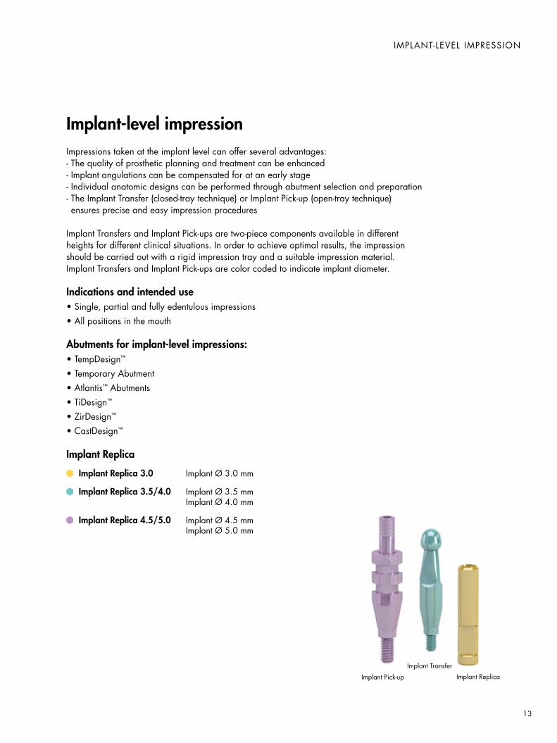
Implant-level impressionImpressions taken at the implant level can offer several advantages: - The quality of prosthetic planning and treatment can be enhanced - Implant angulations can be compensated for at an early stage - Individual anatomic designs can be performed through abutment selection and preparation- The Implant Transfer (closed-tray technique) or Implant Pick-up (open-tray technique) ensures precise and easy impression procedures
Implant Transfers and Implant Pick-ups are two-piece components available in different heights for different clinical situations. In order to achieve optimal results, the impression should be carried out with a rigid impression tray and a suitable impression material. Implant Transfers and Implant Pick-ups are color coded to indicate implant diameter.
Indications and intended use• Single, partial and fully edentulous impressions• All positions in the mouth
Abutments for implant-level impressions:• TempDesign™
• Temporary Abutment• Atlantis™ Abutments• TiDesign™
• ZirDesign™
• CastDesign™
Implant Replica
Implant Replica 3.0 Implant Ø 3.0 mm
Implant Replica 3.5/4.0 Implant Ø 3.5 mm Implant Ø 4.0 mm
Implant Replica 4.5/5.0 Implant Ø 4.5 mm Implant Ø 5.0 mm
Implant Pick-up
Implant Transfer
Implant Replica
13

ImPLAnT-LeVeL ImPReSSIOnClosed tray
Checking the impressionBefore sending the impression and Implant Transfer to the laboratory, make sure there is a sufficient amount of impression material to give a correct and stable retention for the Implant Transfer. If there is more than one implant impressed and there are different platforms or transfer lengths, make sure to identify each. Placing the correct Implant Transfer back into the impression together with the appropriate Implant Replica is recommended to avoid mistakes.
Seating the Implant TransferBefore placing the Implant Transfer, make sure the pin engages the threads in the apical part of the transfer. The pin should not be visible below the indexing as this could prevent the Implant Transfer from being seated correctly.
Use the pin as a carrier to seat the transfer into the implant.
make sure the internal hex is correctly engaged before tightening the pin. Secure the Implant Transfer into the implant by tightening the pin using light finger force.
Removing the impressionOnce the impression material has set, remove the impression.
Unscrew the Implant Transfer.
Taking the impressionPrepare a standard or customized impression tray. make sure there is enough space for the transfer so it will not interfere with the tray.
Inject elastomeric impression material around the Implant Transfer and into the impression tray.
Take the impression.
CLI
nIC
AL
PRO
Ce
DU
Re
14

ImPLAnT-LeVeL ImPReSSIOnOpen tray
Taking the impressionInject elastomeric impression material around the Implant Pick-up and fill the impression tray.
Place the tray filled with impression material intraorally. make sure the Guide Pin penetrates the wax.
Removing the impressionOnce the impression material has set, unscrew the Guide Pin.
Note: make sure that the Guide Pin is completely disengaged from the implant before removing the impression.
Check the impression for correct and stable retention of the Implant Pick-up.
Seating the Implant Pick-upSeat the Implant Pick-up securely into the implant. make sure the internal hex is correctly engaged before tightening the implant Guide Pin with a Hex Screwdriver using light finger force.
Try-in of the impression trayPrepare and use a standard or customized impression tray. make sure the Guide Pin can penetrate the tray without interfering with it. Cover the prepared hole with wax, which is penetrated by the Guide Pin while taking the impression.
CLIn
ICA
L PROC
eDU
Re
15

ImPLAnT-LeVeL ImPReSSIOnWorking model – Closed-/Open-tray impression
Working model – closed-tray impressionThe impression tray with the Implant Transfer is received at the laboratory. It is important that the clinician communicates the information about placed implant diameter to the dental technician for correct replica selection.
make sure the pin engages the threads in the apical part of the Implant Transfer. Tighten the Implant Transfer securely into the Implant Replica using light finger force.
Position the Implant Transfer/Implant Replica in the impression. Check for correct and stable retention of the Implant Transfer.
Fabricate a removable stable silicone soft tissue mask directly in the impression. make sure the soft tissue material covers at least 2 mm of the Implant Replica. Pour high quality stone material into the impression tray. Once the stone material has set, separate the model from the tray.
Working model — open-tray impressionThe impression tray with the Implant Pick-up is received at the laboratory. It is important that the clinician communicates the information about placed implant diameter to the dental technician for correct replica selection.
Pull back the Guide Pin before placing the Implant Replica. Seat the replica on the Implant Pick-up, make sure to engage the hex correctly and tighten the Guide Pin.
Fabricate a removable stable silicone soft tissue mask directly in the impression. make sure the soft tissue material covers at least 2 mm of the Implant Replica. Pour high quality stone material into the impression. Once the stone material has set, unscrew the Guide Pin and separate the model from the tray.
LAB
OR
ATO
Ry P
RO
Ce
DU
Re
16

PeRmAnenT ImPLAnT ReSTORATIOnAtlantis™ Abutments
Atlantis™ AbutmentsImplant-level impression
Atlantis™ Abutments are two-piece component for cement-retained restorations. By utilizing the unique Atlantis VAD™ (Virtual Abutment Design) software, the abutments are individually designed from the final tooth shape and precision machined. Atlantis Abutments are available in the following materials; titanium, gold-shaded titanium (Tin coated) and zirconia, white and shaded. The Atlantis Abutments are designed and produced to provide optimal function and esthetics and further modifications are not needed.
Indications and intended use• Single, partial and fully edentulous situations• All positions in the mouth
Note: Use of zirconia abutments should be carefully evaluated when placed in situations with unfavorable loading conditions.
17

ImpressionTake an implant-level impression using an open- or closed-tray technique.
Send the impression to your laboratory with a request for an Atlantis™ Abutment utilizing Clinic-to-laboratory prescription form.
CementationCover the screw head with silicone before the screw entrance hole is filled with a suitable composite material. Cement the crown onto the abutment. The cementation technique should be adapted to the restoration of choice according to the instructions from the manufacturer. Remove excess cement.
Note: Any modification may influence the mechanical strength and for Atlantis™ Abutments in zirconia there is also a risk for change of material properties, e.g. during grinding.
Abutment installationClean/sterilize and install the Atlantis Abutment into the implant by tightening the Abutment Screw using a Hex Screwdriver and Torque Wrench.
Note: The specific Abutment Screw delivered with the Atlantis Abutment should always be used.
Recommended torque for final seating: 15 Ncm 20 Ncm 25 Ncm
PeRmAnenT ImPLAnT ReSTORATIOnAtlantis™ Abutments
CLI
nIC
AL
PRO
Ce
DU
Re
18

Final restorationWhen the final Atlantis™ Abutment is received at the laboratory, the final restoration can be fabricated.
Note: The Abutment Screw delivered with the specific Atlantis Abutment should always be sent with the abutment to the clinician.
Laboratory Abutment Screws should be used pre-clinically in combination with Atlantis Abutments for the Astra Tech Implant System™.
Design and productionOnce case materials are received, the models are scanned and generated into a virtual 3D image that is then used for the individual design of the Atlantis Abutment in the Atlantis vAD™ software. Review and approve the virtual abutment design (if requested). The Atlantis Abutment is manufactured, inspected and shipped to the laboratory.
Note: Any modification may influence the mechanical strength and for Atlantis™ Abutments in zirconia there is also a risk for change of material properties, e.g. during grinding.
Atlantis™ WebOrderCreate an order in Atlantis™ WebOrder with the abutment design preferences specific for the case. Print and send the order ticket with the required materials in the Atlantis™ CaseSafe box to Astra Tech.
Working modelThe working model should have a removable stable silicone soft tissue mask. All Atlantis™ Abutment cases must be articulated when shipped to Astra Tech. A small articulator/occludator can be used and shipped in the Atlantis™ CaseSafe box that is provided.
Note: If using an articulator with a removable base plate, it may only be necessary to ship the model mounted on the plate and not the entire articulator. Refer to “Shipping and articulator guide” for details.
PeRmAnenT ImPLAnT ReSTORATIOnAtlantis™ Abutments
LAB
ORA
TORy
PROC
eDU
Re
19
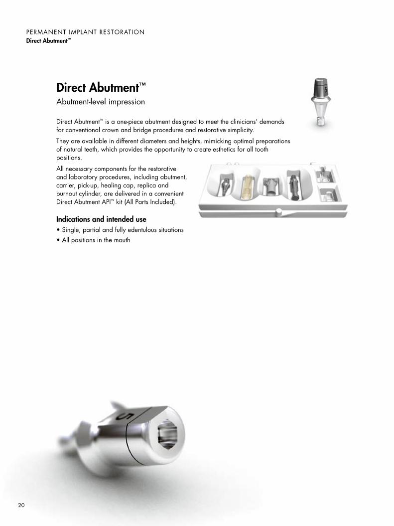
Direct Abutment™Abutment-level impression
Direct Abutment™ is a one-piece abutment designed to meet the clinicians’ demands for conventional crown and bridge procedures and restorative simplicity.
They are available in different diameters and heights, mimicking optimal preparations of natural teeth, which provides the opportunity to create esthetics for all tooth positions.
All necessary components for the restorative and laboratory procedures, including abutment, carrier, pick-up, healing cap, replica and burnout cylinder, are delivered in a convenient Direct Abutment API™ kit (All Parts Included).
Indications and intended use• Single, partial and fully edentulous situations• All positions in the mouth
PeRmAnenT ImPLAnT ReSTORATIOnDirect Abutment™
20

Using the Direct Abutment™ CarrierConnect the Carrier to the Direct Abutment™ after sterilization. verify orientation of the flat surface and seat firmly.
PeRmAnenT ImPLAnT ReSTORATIOnDirect Abutment™
Abutment selectionSelect a suitable Direct Abutment™, taking into consideration diameter and vertical height and using try-in abutments or the Abutment Depth Gauge.
Abutment installation – Direct Abutment™ Ø 5 and 6 mmInstall the cleaned and sterilized Direct Abutment™ into the implant.
Place the Torque Wrench directly on the carrier and tighten the abutment. Press downwards on the carrier during this procedure.
As an alternative, the Torque Wrench Bit Hex may be used for Direct Abutment Ø 5 and 6 mm.
Recommended torque for final seating: 25 Ncm 25 Ncm
Abutment installation – Direct Abutment™ Ø 4 mmInstall the cleaned and sterilized Direct Abutment™ Ø 4 into the implant with the Direct Abutment metal Carrier 4.
Place the Torque Wrench directly on the carrier and tighten the abutment. Press downwards on the carrier during this procedure.
Recommended torque for final seating: 25 Ncm 25 Ncm
CLIn
ICA
L PROC
eDU
Re
21

PeRmAnenT ImPLAnT ReSTORATIOnDirect Abutment™
Abutment-level impression To take an abutment-level impression, align the flat surface of the abutment with the raised knob on the Impression Pick-up and seat the pick-up firmly by snap ping it into place.
Use a closed-tray impression technique. Inject elastomeric impression material and take the impression.
Check the impression for correct and stable retention of the Impression Pick-up.
Note: Do not autoclave or reuse the Impression Pick-up.
Take an impression using the Impression Pick-up and a closed tray. The Healing Cap can still be used on the abutment.
Note: It is important to inform the dental technician about the occlusal reduction.
Occlusal reduction of the abutment (optional)The laser-etched band on the abutment and corresponding replica provide precise indicators when 1 mm reduction is needed.
Reducing the occlusal height by a maximum of 1 mm will ensure that sufficient material is maintained for the friction grip required by the Carrier and Hex Screwdriver.
To ensure a perfect fit of the final crown, the abutment should be reduced just below the laser marking by the clinician, while the Abutment Replica is reduced just above the laser marking by the dental technician.
TemporizationA Healing Cap can be used in combination with the Direct Abutment™ as a temporary solution.
Snap the Healing Cap onto the Direct Abutment, making sure that the cap is seated all the way down on the abutment. For further retention, temporary cement can be used.
The Healing Cap can also be used as a base to fabricate a temporary restoration.
CLI
nIC
AL
PRO
Ce
DU
Re
22

Working modelThe impression tray with the Impression Pick-up is received at the laboratory. Seat the Direct Abutment™ Replica in the Impression Pick-up. Verify the orientation of the flat surface to ensure the correct position. The replicas have laser markings to simplify identification.
Fabricate a removable soft tissue mask directly in the impression. make sure the soft tissue material covers at least 2 mm of the replica.
Pour high-quality stone material into the impression tray.
Crown fabricationPosition the Direct Abutment™ Burnout Cylinder on the abutment replica. Align the flat surface of the replica with the chimney of the Burnout Cylinder. The Burnout Cylinder has a built-in cement space.
Fabricate the crown restoration.
Note: For burnout procedures do not burnout the wax and plastic too quickly to avoid defects in the investment material.
Clean and prepare the crown for delivery to the clinic.
Occlusal reduction of the replica (optional)The laser-etched band on the abutment and corresponding replica provide precise indicators when 1 mm reduction is needed. Reducing the occlusal height by a maximum of 1 mm will ensure that sufficient material is maintained for the friction grip required by the Carrier and Hex Screwdriver. To ensure a perfect fit of the final crown, the abutment should be reduced just below the laser marking by the clinician, while the Abutment Replica is reduced just above the laser marking by the dental technician.
Seat the Direct Abutment™ Replica in the Impression Pick-up and fabricate a working model.
Fabricate the crown restoration following standard working procedures.
Note: If the Burnout Cylinder is used, make sure to adjust it to the reduction of the replica.
PeRmAnenT ImPLAnT ReSTORATIOnDirect Abutment™
LAB
ORA
TORy
PROC
eDU
Re
23

Final resultRemove excess cement.
CementationCement the crown onto the abutment. The cementation technique should be adapted to the restoration of choice according to the instructions from the manufacturer.
PeRmAnenT ImPLAnT ReSTORATIOnDirect Abutment™
CLI
nIC
AL
PRO
Ce
DU
Re
24

TiDesign™
Implant-level impression
TiDesign™ offers an opportunity to create individual solutions regarding function and esthetics following the principles of traditional restorative cement-retained procedures used on natural teeth.
TiDesign is a two-piece component, pre-designed for fast and simple handling. The design and dimension of TiDesign is well-suited for cases requiring compensation for deviations between implants or when misalignments are dictated by anatomical conditions.
Indications and intended use• Single, partial and fully edentulous situations• All positions in the mouth
25

ModificationUnscrew the abutments from the working model and screw it into the Implant Replica using the Laboratory Abutment Screw and mount in the Grinding Handle for easy handling.
Grind the abutments using grinders specially manufactured for titanium. Follow standard guidelines for tooth preparation used in regular crown and bridgework. The abutments can be prepared to meet angulations as long as retention is created.
Note: make sure not to damage the implant interface part of the abutment during modification of the abutment.
Final restorationBlock the abutment screw access holes in the model with suitable material.
Fabricate and finalize the restoration. Sandblast, grind or polish the abutments according to the clinician’s preference.
Clean and prepare the abutments and restoration for delivery to the clinic.
Note: A transfer key can be made to simplify the positioning of the abutments in the mouth.
OutlinePlace the selected TiDesign™ in the Implant Replica using the Laboratory Screw and the Hex Screwdriver. Check for fit with the soft tissue mask.
Outline the soft-tissue margin, the correct vertical dimension and the mesial-distal width on the abutments, using a fine-tip permanent marker.
Abutment selectionUse the abutment size as determined by use of try-in abutments or by using the Abutment Depth Gauge.
PeRmAnenT ImPLAnT ReSTORATIOnTiDesign™
LAB
OR
ATO
Ry P
RO
Ce
DU
Re
26

CementationCover the screw head with silicone before the screw entrance hole is filled with a suitable composite material. Cement the bridge onto the abutments. The cementation technique should be adapted to the restoration of choice and according to the instructions from the manufacturer.
Remove excess cement.
Note: With the exception of ”Abutment selection” these handling procedures also apply for Profile BiAbutment.
Final tighteningTighten the Abutment Screws using the Hex Screwdriver and Torque Wrench.
Recommended torques for final seating: 15 Ncm 20 Ncm 25 Ncm
Transfer keyA transfer key is recommended to ensure the accurate positioning of the TiDesign™ abutments.
Abutment installationRemove the temporary restoration and install the cleaned and sterilized abutments with the Abutment Screw using the Hex Screwdriver.
PeRmAnenT ImPLAnT ReSTORATIOnTiDesign™
CLIn
ICA
L PROC
eDU
Re
27

PeRmAnenT ImPLAnT ReSTORATIOnZirDesign™
ZirDesign™
Implant-level impression
ZirDesign™ is a two-piece component fabricated in zirconia. It is easily modified to support a very esthetic, anatomically-designed prosthetic solution. ZirDesign is intended for use in the anterior and pre-molar regions and comes in an angled version to meet more demanding implant angulations. It is not recommended for use in the molar regions.
ZirDesign is pre-shaped with a scalloped prosthetic margin, which requires minimal modifications.
Indications and intended use• Single and partial edentulous situations• Anterior, canine and premolar
Note: Use of zirconia abutments should be carefully evaluated when placed in situations with unfavorable loading conditions.
Technical dataCoefficient of thermal linear expansion: 10.6 x 10⁻⁶ K-1
Bending strength: 1000–1300 mPa Fracture toughness: 9–10 mPa m1/2
modulus of elasticity: 210 GPa
28
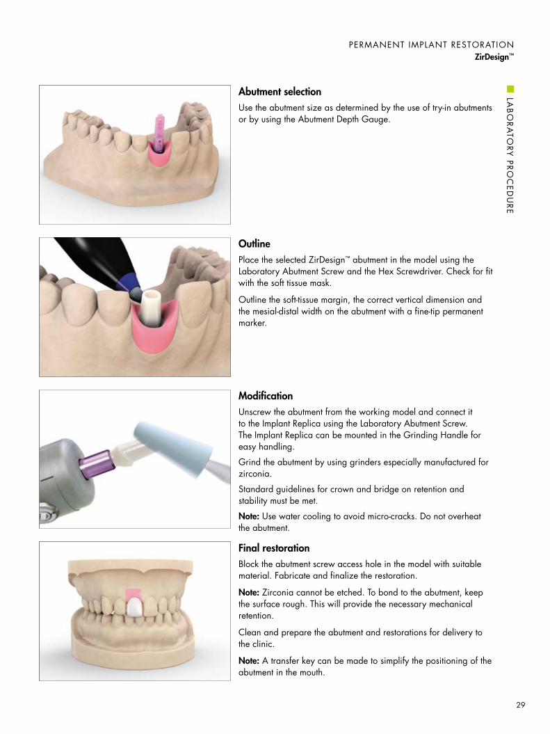
Final restorationBlock the abutment screw access hole in the model with suitable material. Fabricate and finalize the restoration.
Note: Zirconia cannot be etched. To bond to the abutment, keep the surface rough. This will provide the necessary mechanical retention.
Clean and prepare the abutment and restorations for delivery to the clinic.
Note: A transfer key can be made to simplify the positioning of the abutment in the mouth.
ModificationUnscrew the abutment from the working model and connect it to the Implant Replica using the Laboratory Abutment Screw. The Implant Replica can be mounted in the Grinding Handle for easy handling.
Grind the abutment by using grinders especially manufactured for zirconia.
Standard guidelines for crown and bridge on retention and stability must be met.
Note: Use water cooling to avoid micro-cracks. Do not overheat the abutment.
OutlinePlace the selected ZirDesign™ abutment in the model using the Laboratory Abutment Screw and the Hex Screwdriver. Check for fit with the soft tissue mask.
Outline the soft-tissue margin, the correct vertical dimension and the mesial-distal width on the abutment with a fine-tip permanent marker.
Abutment selectionUse the abutment size as determined by the use of try-in abutments or by using the Abutment Depth Gauge.
PeRmAnenT ImPLAnT ReSTORATIOnZirDesign™
LAB
ORA
TORy
PROC
eDU
Re
29
PeRmAnenT ImPLAnT ReSTORATIOnZirDesign™
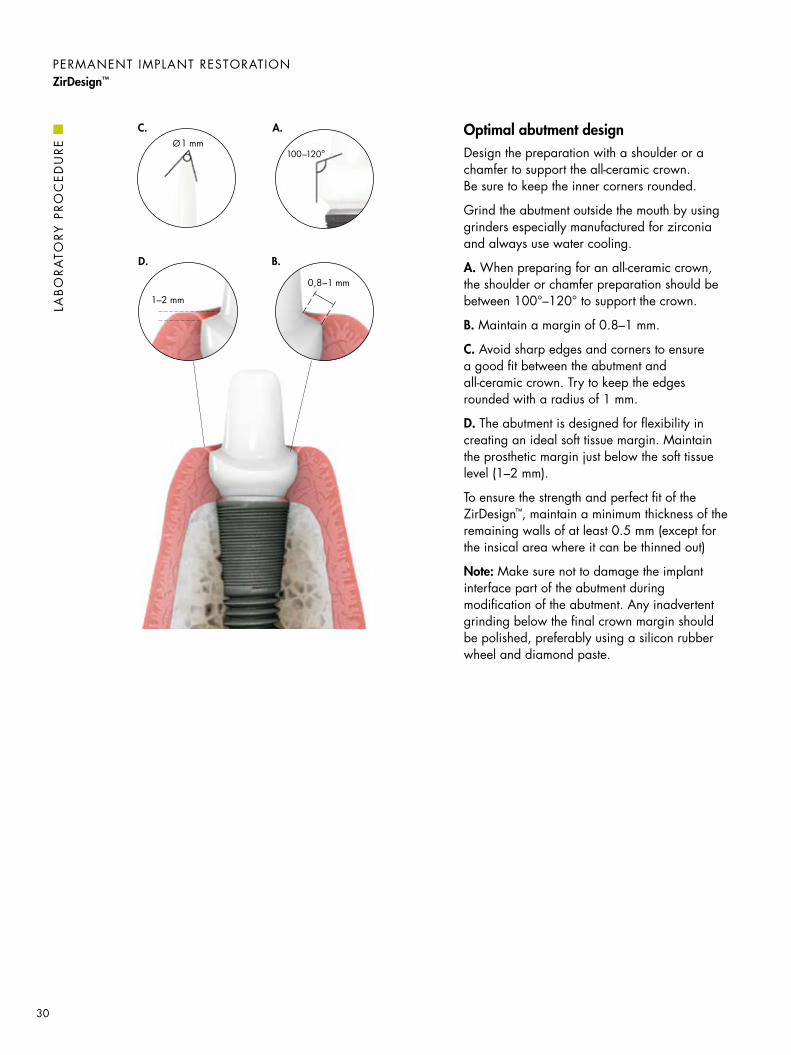
Optimal abutment designDesign the preparation with a shoulder or a chamfer to support the all-ceramic crown. Be sure to keep the inner corners rounded.
Grind the abutment outside the mouth by using grinders especially manufactured for zirconia and always use water cooling.
A. When preparing for an all-ceramic crown, the shoulder or chamfer preparation should be between 100°–120° to support the crown.
B. maintain a margin of 0.8–1 mm.
C. Avoid sharp edges and corners to ensure a good fit between the abutment and all-ceramic crown. Try to keep the edges rounded with a radius of 1 mm.
D. The abutment is designed for flexibility in creating an ideal soft tissue margin. maintain the prosthetic margin just below the soft tissue level (1–2 mm).
To ensure the strength and perfect fit of the ZirDesign™, maintain a minimum thickness of the remaining walls of at least 0.5 mm (except for the insical area where it can be thinned out)
Note: make sure not to damage the implant interface part of the abutment during modification of the abutment. Any inadvertent grinding below the final crown margin should be polished, preferably using a silicon rubber wheel and diamond paste.
A.C.
D.
1–2 mm
B.
0,8–1 mm
Ø1 mm100–120°
LAB
OR
ATO
Ry P
RO
Ce
DU
Re
30

Remove excess cement.
Note: Zirconia cannot be etched. To bond to the abutment, keep the surface rough. This will provide the necessary mechanical retention.
CementationCover the screw head with silicone before the screw entrance hole is filled with a suitable composite material.
Cement the crown onto the abutment. The permanent cementation can be done with glass-ionomer or composite cement depending on the type of restoration. The cementation technique should be adapted to the restoration of choice according to the instructions from the manufacturer.
Final tighteningTighten the abutment in the implant with the Abutment Screw using the Hex Screwdriver and Torque Wrench.
Recommended torques for final seating: 20 Ncm 25 Ncm
Abutment installationRemove the temporary restoration and install the cleaned and sterilized* ZirDesign™ with the Abutment Screw using the Hex Screwdriver. To ensure correct position, try in the crown or use a transfer key before final tightening of the Abutment Screw.
*Note: Zirconia should not be sterilized in a steam autoclave.
PeRmAnenT ImPLAnT ReSTORATIOnZirDesign™
CLIn
ICA
L PROC
eDU
Re
31

PeRmAnenT ImPLAnT ReSTORATIOnCastDesign™
CastDesign™
Implant-level impression
CastDesign™ is recommended for fabrication of a customized abutment for both screw and cement-retained restorations, using regular wax-up and cast-to techniques. It provides great flexibility for creating excellent individualized esthetics even if the soft tissue is very thin.
CastDesign™ is useful for solving complicated cases that require angulation corrections up to 30°.
Indications and intended use• Single, partial and fully edentulous situations• For all positions in the mouth• Cement-retained single crown and bridge restorations• One-piece screw-retained single restoration
Technical datamelting range: 1400–1490°C/2552–2660°F
Coefficient of thermal linear expansion for alloy: 25–500°C /77–932°F 12.3 (10–6/°C) 25–600°C /77–1112°F 12.7 (10–6/°C)
32

Invest, burnout and castInvest the waxed abutment.
Burnout and cast the abutment by using an alloy compatible with the CastDesign™ metal thermal expansion coefficient.
Note: The cast-on alloy must have a casting temperature that is below the solidus (1400°C/2552°F) of the CastDesign.
The CastDesign absorbs a lot of heat during burnout and casting. make sure to compensate for this by: • Increasing the time for the burnout and preheating procedures• Raising the temperature slowly and increasing the final burnout
temperature by approximately 100°C/212°F.
Wax thicknessmake sure the wax-up is thick enough to avoid a miscast.
Do not remove the plastic around the metal cylinder.
Wax-upThe abutment is shaped in wax and casted with a suitable metal to support the cemented crown.
Create the crown margin, which is normally placed 1–2 mm below the soft tissue margin. Check the wax-up for occlusal and mesial-distal clearance, allowing enough crown material in all directions.
ModificationThe impression is recorded at implant-level and a working model with soft tissue mask and replica is fabricated.
make sure the soft tissue material has enough thickness and extension and can be repositioned easily.
The plastic cylinders on the CastDesign™ are modified at the laboratory. The abutment can be prepared to meet angulations as long as sufficient retention is present.
PeRmAnenT ImPLAnT ReSTORATIOnCastDesign™
LAB
ORA
TORy
PROC
eDU
Re
33

Final restorationBlock the Abutment Screw access holes in the model with suitable material. Apply cement spacer. Fabricate and finalize the restoration.
Clean and prepare the abutments and restoration for delivery to the clinic.
Screw-retained abutment/crown (optional)If a single tooth screw-retained restoration is required, the CastDesign™ can be used. The wax-up of the abutment should then be done to support an even layer of porcelain.
make sure there is a significant thickness of the casting alloy covering the abutment, as the non-oxidizing alloy of the CastDesign is not intended for direct porcelain firing, which could cause the porcelain to crack.
Transfer keyA transfer key can be made to simplify the abutment positioning in the mouth. Openings in the key should permit access to the Abutment Screws.
Finishing the abutmentDevest the abutment using glass beads. make sure the screw access hole is free from investment material.
Connect the abutment into the Implant Replica using the Laboratory Abutment Screw and mount it in the Grinding Handle for easy handling. Finalize the abutment.
Note: make sure not to damage the conical part of the abutment during blasting and grinding of the abutment.
PeRmAnenT ImPLAnT ReSTORATIOnCastDesign™
LAB
OR
ATO
Ry P
RO
Ce
DU
Re
34
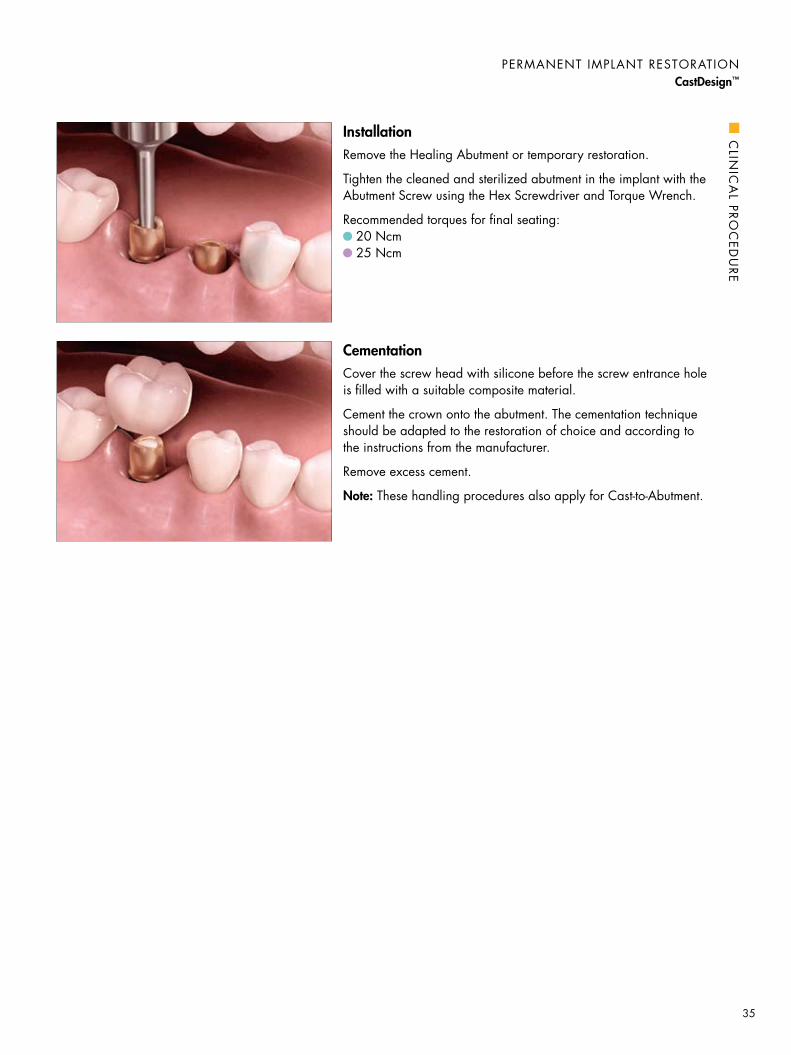
CementationCover the screw head with silicone before the screw entrance hole is filled with a suitable composite material.
Cement the crown onto the abutment. The cementation technique should be adapted to the restoration of choice and according to the instructions from the manufacturer.
Remove excess cement.
Note: These handling procedures also apply for Cast-to-Abutment.
InstallationRemove the Healing Abutment or temporary restoration.
Tighten the cleaned and sterilized abutment in the implant with the Abutment Screw using the Hex Screwdriver and Torque Wrench.
Recommended torques for final seating: 20 Ncm 25 Ncm
PeRmAnenT ImPLAnT ReSTORATIOnCastDesign™
CLIn
ICA
L PROC
eDU
Re
35

TORqUe GUIDe
Type of product Torque – Ncm
* Only light finger force (5–10 ncm) using a manual screwdriver or contra angle preset at 25 rpm and 5–10 ncm torque. ** Only light finger force (5–10 ncm) using a manual screwdriver. Do not use a Ratchet Wrench or Torque Wrench. *** Note: Available for TiDesign™, Atlantis™ Abutment – titanium and Atlantis™ Abutment – GoldHue™.
– 25 25
Direct Abutment™
Ball AbutmentLocator™ Abutment
Atlantis™ Abutments for Astra Tech Implant System™
ZirDesign™
TiDesign™
CastDesign™
Angled Abutment
15*** 20 25
20°/45° Cresco™ Insert for Astra Tech Implant System™
20°/45° UniAbutment
Bridge ScrewsCresco™ Bridge Screw
TempDesign™
Temporary Abutment
– 15 15
– 15 15
15 15 15
– 15 15
Cover Screw
Healing AbutmentHealing Abutment UniProHeal CapHealing Cap Angled
manual* manual* manual*
manual** manual** manual**
X-Small Small Large
Recommended tightening torque
36

Abutment Sterilization procedure
Atlantis™ Abutments – titanium
Atlantis™ Abutments – GoldHue™
Direct Abutment™
TiDesign™
Temporary Abutment/TempDesign™
CastDesign™
Try-in Abutment
Abutment Screw
Steam sterilization with a pre-vacuum cycle (134°C/270–275°F for 3 minutes).
Atlantis™ Abutments – zirconia, white and shaded Dry Heat(160°C/320°F for 2 hours) or Liquid Chemical Sterilization / High Level Disinfection is recommended.*
ZirDesign™ Liquid Chemical Sterilization / High Level Disinfection is recommended.*
Healing Abutment Sterile when delivered.
Cleaning and sterilization proceduresBefore installation, the abutments must undergo a cleaning and sterilization procedure. The cleaning should preferably take place in an ultrasonic unit with a mixture of dishwashing detergent and water. For sterilization procedures, follow the instructions below.
*Note: Zirconia should not be sterilized in a steam autoclave. The process can affect the mechanical properties of the material.
CLeAnInG AnD STeRIL IZATIOn PROCeDUReS
37

REFERENCES
Fixed partial restorationDiss A, Dohan Dm, mouhyi J, mahler P. Osteotome sinus floor elevation using Choukroun’s platelet-rich fibrin as grafting material: a 1-year prospective pilot study with microthreaded implants. Oral Surg Oral med Oral Pathol Oral Radiol endod 2008;105(5):572-9.
Larsson C, Vult von Steyern P, Sunzel B, nilner K. All-ceramic two- to five-unit implant.supported reconstructions. A randomized, prospective clinical trial. Swed Dent J 2006;30(2):45-53.
Lee DW, Park KH, moon IS. Dimension of interproximal soft tissue between adjacent implants in two distinctive implant systems. J Periodontol 2006;77(6):1080-4.
Palmer Rm, Howe LC, Palmer PJ. A prospective 3-year study of fixed bridges linking Astra Tech ST implants to natural teeth. Clin Oral Implants Res 2005;16(3):302-7. (Ref. no. 78300)
Single tooth restorationCooper LF, ellner S, moriarty J, Felton DA, Paquette D, molina A, et al. Three-year evaluation of single-tooth implants restored 3 weeks after 1-stage surgery. Int J Oral maxillofac Implants 2007;22(5):791-800. (Ref. no. 78988)
De Kok IJ, Chang SS, moriarty JD, Cooper LF. A retrospective analysis of peri-implant tissue responses at immediate load/provisionalized microthreaded implants. Int J Oral maxillofac Implants 2006;21(3):405-12. (Ref. no. 78727, 78776)
Donati m, La Scala V, Billi m, Di Dino B, Torrisi P, Berglundh T. Immediate functional loading of implants in single tooth replacement: a prospective clinical multicenter study. Clin Oral Implants Res 2008;19:740-48. (Ref. no. 79065)
Gotfredsen K. A 5-year prospective study of single-tooth replacements supported by the Astra Tech implant: a pilot study. Clin Impl Dent Rel Res 2004;6(1):1-8. (Ref. no. 78273)
Karlsson U, Gotfredsen K, Olsson C. Single-tooth replacement by osseointegrated Astra Tech dental implants: a 2-year report. Int J Prosthodont 1997;10(4):318-24. (Ref. no. 75067)
norton mR. The Astra Tech single-tooth implant system: a report on 27 consecutively placed and restored implants. Int J Periodontics Rest Dent 1997;17(6):575-83. (Ref. no. 75184)
norton mR. Biologic and mechanical stability of single-tooth implants: 4- to 7-year followup. Clin Impl Dent Rel Res 2001;3(4):214-20. (Ref. no. 75417)
norton mR. A short-term clinical evaluation of immediately restored maxillary TiOblast single-tooth implants. Int J Oral maxillofac Implants 2004;19(2):274-81. (Ref. no. 78173)
norton mR. multiple single-tooth implant restorations in the posterior jaws: maintenance of marginal bone levels with reference to the implant-abutment microgap. Int J Oral maxillofac Implants 2006;21(5):777-84. (Ref. no. 78773)
Steveling H, Roos J, Rasmusson L. maxillary implants loaded at 3 months after insertion: results with Astra Tech implants after up to 5 years. Clin Impl Dent Rel Res 2001;3(3):120-4. (Ref. no. 75414)
Wennström JL, ekestubbe A, Gröndahl K, Karlsson S, Lindhe J. Implant-supported single-tooth restorations: a 5-year prospective study. J Clin Periodontol 2005;32(6):567-74. (Ref. no. 78476)
References supporting cement-retained restorations with Astra Tech Implant System™
38


7935
5-U
S-10
10 ©
201
0 A
stra
Tech
Astra Tech Inc., USA: 590 Lincoln Street, Waltham, MA 02451. Tel: 800-531-3481. Fax: 781-890-6808. www.astratechdental.comCanada: 2425 Matheson Boulevard E., 8th Floor, Mississauga, ON, L4W 5K4. Tel: 866-427-8327. Fax: 905-361-2629
Prin
ted
in U
SA
11/
10
OsseoSpeed™
MicroThread™
Conical Seal Design™
Connective Contour™
Astra Tech BioManagement Complex™
A successful implant system cannot be determined by one single feature alone. Just as in nature, there must be several interdependent features working together. The following combination of key features is unique to the Astra Tech Implant System™:
• OsseoSpeed™— more bone more rapidly
• MicroThread™— biomechanical bone stimulation
• Conical Seal Design™— a strong and stable fit
• Connective Contour™— increased soft tissue contact zone and volume