Embed Size (px)
Citation preview
WELDING RESEARCH
-s231WELDING JOURNAL
ABSTRACT. Double-electrode gas metalarc welding (DE-GMAW) is a novelprocess that decouples the melting currentinto base metal current and bypass currentby adding a bypass torch to a conventionalGMAW system to establish a bypass arc.This makes it possible to increase themelting current while the base metalcurrent can be controlled at a desired level.Experiments have been done to find theconditions that can assure a stable bypassarc is established/maintained between thewelding wire and the bypass torch. Tocontrol the base metal current at thedesired level, a group of power resistors isadded in the bypass loop. The resistance ofthe power resistor group is adjusted real-time by changing the combination of theresistors, and the change in the resistanceresults in a change in the bypass currentand thus a change in the base metalcurrent. A model has been developed tocorrelate the change of the resistanceneeded to achieve the desired base metalcurrent to the deviation of the base metalcurrent from its desired level. Experimentsdemonstrated that the developed controlsystem can adjust the bypass current in agreat range to maintain the base metalcurrent at the desired levels.
Introduction
Gas metal arc welding (GMAW) is amajor process for metals joining.Conventional GMAW is normally used inthe direct current electrode positivepolarity (DCEP), in which the wire isconnected to the positive terminal of thepower source and the power sourceoperates in the constant voltage (CV)mode. The reverse polarity contributes toa stable arc, uniform metal transfer, andgreater penetration. A CV power sourcecan adjust the welding current such thatthe wire melting rate is equal to the givenwire feed speed, and the welding voltage,
or arc length, is maintained constant. Forautomatic and semiautomatic welding, theproductivity is mostly determined by thetravel speed provided that the weldingperformance criterion is met, for example,the cross-section area of the weld bead isnot changed with the travel speed.Obviously, a faster travel speed requires alarger wire melting rate such that themelted metal is enough to form a longerweld bead in a unit time. Based on thework by Waszink and Heuvel (Ref. 1), themelting rate can be calculated by thefollowing formula if the metal transfer isin spray mode, i.e., the melting current isgreater than 250 A for mild steels.
(1)where m (kg/s) is the melting rate, I (A) isthe total melting current, L (m) is the wireextension, and S (m2) is the cross-sectionalarea of the wire. That means the meltingcurrent must be increased in order toincrease the melting rate. Unfortunately,the melting current in conventionalGMAW is the same as the base metalcurrent. Thus, a greater melting currentnot only melts the wire faster, but alsoincreases the based metal heat input,which contributes to increasing the weldpool, residual stress, and distortion. Thisfundamental characteristic of conventionalGMAW makes it difficult to increase thedeposition rate without imposing excessive heatto the base metal.
While tandem GMAW (Refs. 2, 3), T.I.M.E(Refs. 4, 5), and variable-polarity GMAW (Refs.6–8) have successfully increased the melting rateto certain degrees without changing thisfundamental characteristic of conventional
GMAW, the double-electrode GMAW process(Ref. 9) proposes a way to change thisfundamental characteristic so that themelting rate can be freely increased. In aprevious preliminary study (Ref. 9), thischange was realized by adding a plasmatorch and a second power supply to aconventional GMAW system. In thisstudy, the DE-GMAW process isimplemented without the second powersupply. In addition, the plasma torch isreplaced by a gas tungsten arc weldingtorch which is more durable and costeffective.
Principles of DE-GMAW
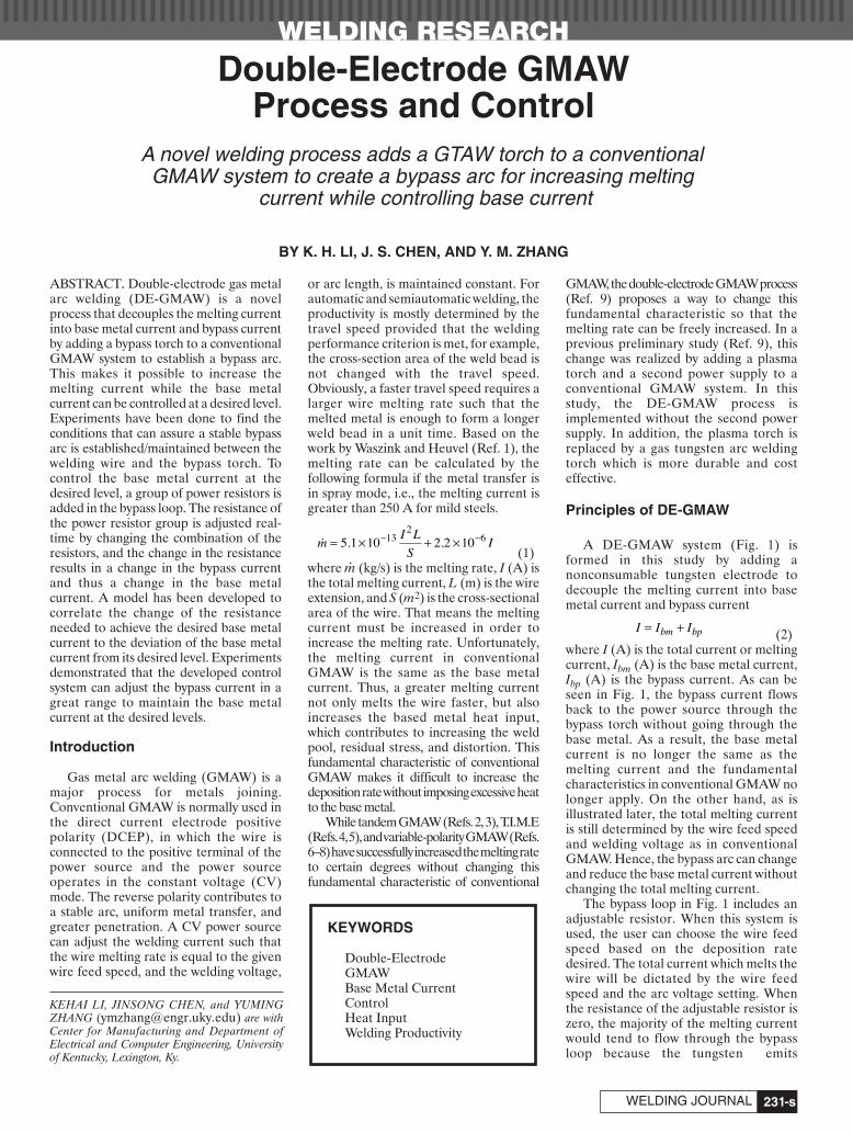
A DE-GMAW system (Fig. 1) isformed in this study by adding anonconsumable tungsten electrode todecouple the melting current into basemetal current and bypass current
(2)where I (A) is the total current or meltingcurrent, Ibm (A) is the base metal current,Ibp (A) is the bypass current. As can beseen in Fig. 1, the bypass current flowsback to the power source through thebypass torch without going through thebase metal. As a result, the base metalcurrent is no longer the same as themelting current and the fundamentalcharacteristics in conventional GMAW nolonger apply. On the other hand, as isillustrated later, the total melting currentis still determined by the wire feed speedand welding voltage as in conventionalGMAW. Hence, the bypass arc can changeand reduce the base metal current withoutchanging the total melting current.
The bypass loop in Fig. 1 includes anadjustable resistor. When this system isused, the user can choose the wire feedspeed based on the deposition ratedesired. The total current which melts thewire will be dictated by the wire feedspeed and the arc voltage setting. Whenthe resistance of the adjustable resistor iszero, the majority of the melting currentwould tend to flow through the bypassloop because the tungsten emits
�mI L
SI= × + ×− −5 1 10 2 2 1013
26. .
I I Ibm bp= +
KEYWORDS
Double-ElectrodeGMAWBase Metal CurrentControlHeat InputWelding Productivity
Double-Electrode GMAW Process and Control
A novel welding process adds a GTAW torch to a conventional GMAW system to create a bypass arc for increasing melting
current while controlling base current
BY K. H. LI, J. S. CHEN, AND Y. M. ZHANG
KEHAI LI, JINSONG CHEN, and YUMINGZHANG ([email protected]) are withCenter for Manufacturing and Department ofElectrical and Computer Engineering, Universityof Kentucky, Lexington, Ky.
.
Li 8 07layout:Layout 1 8/6/07 5:00 PM Page 231
WELDING RESEARCH
AUGUST 2007, VOL. 86-s232
electrons easier than the workpiece. Tocontrol the base metal current at thedesired level, the resistance of theadjustable resistor is feedback adjustedusing a current sensor that measures thebase metal current — Fig. 1.
It is apparent that the heat absorbed bythe tungsten and the power resistor iswasted. However, this heat would beapplied to the base metal if the bypassloop is not applied as in conventionalGMAW so that the base metal is over-heated. That is, in conventional GMAW,this heat is not only wasted, but alsoproduces harm to the process.
Process Stability
The presence of the bypass arc is thefundamental characteristic of the DE-GMAW process. A stable bypass arcassures the DE-GMAW function. Hence,the behavior and stability of the bypass arcmust be studied and understood. For thenovel DE-GMAW system demonstratedin Fig. 1, the behavior and stability of thebypass arc were determined by severalparameters discussed below.
Bypass Electrode
In the proposed DE-GMAW process,there are two cathodes: one is theworkpiece, and the other is the bypasselectrode, which forms the bypass arc withthe welding wire. The bypass electrodemust have a high melting point and goodelectrical conductivity. Two materials havebeen tested during the implementation:water-cooled copper and tungsten. Butthe former appears too “cold” to ignite thebypass arc even though it is very close tothe GMAW arc. It was found the tungstenelectrode is a very active bypass electrode,as it is used in GTAW. Thus, a commercialGTAW torch is used to hold the tungstenelectrode and at the same time to providethe shielding gas for the bypass electrode.With a tungsten bypass electrode, the arcstability is significantly improved.
Shielding Gas for Bypass Electrode
To protect the tungsten electrode fromoxidizing, pure argon is recommended forshielding gas. Because of the action ofelectric field and arc radiation, the argonwill be ionized. This ionized argonatmosphere further improves the stabilityof the bypass arc. If the bypass current ishigher than 150 A, a water-cooling systemis required to protect the bypass torch.
Tungsten-to-Welding Wire Distance
The horizontal distance from thetungsten end to the welding wire end, d3 inFig. 2, is also an important parameter toobtain a stable DE-GMAW process. It wasfound that a distance in the range from 2to 5 mm is optimal for achieving a stablebypass arc. A greater d3 will increase thedifficulty to start the bypass arc. A shorterd3 will expedite the melt-off of thetungsten electrode.
Tungsten-to-Workpiece Distance
The distance between the tungstenelectrode and the workpiece, d2 in Fig. 2,cannot be too large in order to start thebypass arc. In DE-GMAW process, theGMAW gun feeds in the welding wire tostrike the main arc between the weldingwire and the workpiece. The bypass arc isthen ignited via the main arc. To assure thebypass arc is ignited, the tungstenelectrode has to be close enough to themain arc. Experiments revealed that theoptimal value of d2 is about 6 mm.
Contact Tube-to-Workpiece Distance
The contact tube-to-workpiece distance(CTWD) d1, as shown in Fig. 2, is alsoimportant for achieving a stable bypass arc.A relatively longer d1 is required in order toprovide the space for the bypass torch in thecurrent implementation. Experimentalobservation showed that the optimaldistance d1 is approximately 20 mm. The
welding voltage for the GMAW powersource is preset around 28–35 Vcorrespondingly.
Angle between Tungsten and Welding Wire
Another parameter that determinesthe behavior and stability of the bypass arcis the angle θ between the tungsten andthe welding wire, illustrated in Fig. 2. TheGMAW gun is placed at a normal workposition. The angle θ can be adjusted bychanging the position of the bypass torch.Because the tungsten electrode needs topoint to the weld pool, the angle θ cannotbe too large. Considering the size of thebypass torch and the distance d1, the angleθ is limited to around 60 deg.
Control System
The control system consisted of anadjustable power resistor group controlledby IGBTs (isolated gate bipolartransistors), two current sensors to detectthe base metal current and bypass current,and a PC to run the control program. Thecontrollable power resistor group shown inFig. 3 includes four individual parallelpower resistors, and each is controlled byan IGBT. When the IGBT is in “ON”status, the corresponding power resistorwill be used in parallel with other resistors.Those IGBTs can be switched ON/OFFvery quickly in several milliseconds tochoose the parallel power resistors, andthen adjust the resistance of the powerresistor group. Assume all four powerresistors have the same resistance(R1=R2=R3=R4=R), then the nominalresistance r of the power resistor group isR/N, where N is the number of IGBTs inON status in the resistor combination. Thepossible nominal resistances are R/4, R/3/,R/2, R, and infinite (when N = 0). If theIGBT connected to Ri,i = 2,3,4, is ON, thenthe IGBT connected to Ri–1 must be ON.
Because the power resistor group wasconnected in series with the bypass torch (a
Fig. 1 — Proposed DE-GMAW system. Fig. 2 — Relationship between tungstenelectrode, welding wire, and workpiece.
Fig. 3 — Controllable power resistor group.
Li 8 07layout:Layout 1 8/6/07 5:00 PM Page 232
WELDING RESEARCH
-s233WELDING JOURNAL
GTAW torch), any change in the resistancewill affect the bypass current, and furtheraffect the base metal current based onEquation 2 because the total current doesnot change when the wire feed speed andthe welding voltage are given.
System Modeling and ControlAlgorithm
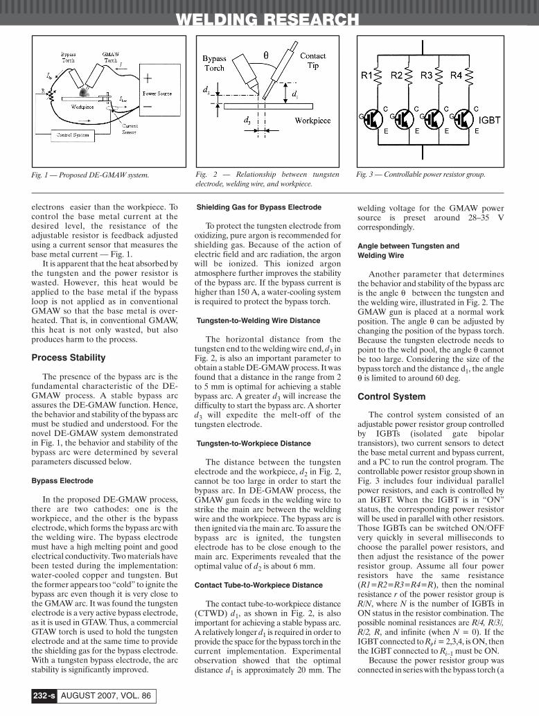
In a stable DE-GMAW process, thetwo arcs can be simplified as two parallelresistors, as shown in Fig. 4. Because thevoltage across the two terminals of thepower supply is controlled at a presetconstant, the sum of the bypass arc voltageand the voltage across the adjustablepower resistor group is constant duringDE-GMAW. Also, the bypass arc voltagemeasured between the two electrodes onlychanges slightly (will be experimentallyverified later in this paper) when thebypass arc current changes. Hence, in astable DE-GMAW process, the voltageacross the power resistor group (Fig. 4B)can only change slightly when the bypasscurrent is adjusted.
Now assume there is a change ΔIbp inthe bypass current, there must be a change Δr in the resistance of the power resistorgroup such that the voltage across thepower resistors does not change. Thus,
(3)
where Ibp0 and r0 represent the bypasscurrent and resistance before the change,and Ibp0+Δbp and r0+Δr are their valuesafter the change. Equation 3 can berewritten as
(4)In comparison with other two terms inEquation 4, ΔIbp Δr can be omitted as ahigher order small number. Hence,Equation 4 can be approximated by
(5)As a result
(6)Equation (6) implies that the
resistance of the power resistor groupshould be decreased if the bypass currentneeds to be increased, and vice versa. In astable DE-GMAW process, the totalcurrent is approximately fixed(determined by the wire feed speed). If thebase metal current is greater than therequired level, the bypass current must beincreased to reduce the base metal currentas it can be seen in Equation 2. To this end,the change of the bypass current should beequal to the negative change of the basemetal current. That means,
(7)
where ΔIbp = Ibp – Ibp0, δIbm = Δ I*bm – Ibm,
Ibp is the measured bypass current, andI*
bm is the desired base metal current.Submit Equation 7 into 6, an equation canbe obtained to determine how theresistance should change
(8a)
To assure a robust control, the needed
adjustment of the resistance should becompleted in a few steps so that thefollowing algorithm may be used for eachadjustment
(8b)
with a positive ratio K<1. While a larger Kimplies a relatively aggressive control or a
Δr Kr
II
bpbm= 0
0δ
Δrr
II
bpbm= 0
0δ
ΔI Ibp bm= −δ
I r I I r rbp bp bp0 0 0 0= +( ) +( )Δ Δ
Δ Δ Δ ΔI r I r I rbp bp bp0 0 0+ + =
Δ ΔI r I rbp bp0 0 0+ =
ΔΔ
rI
Ir
bp
bp= −
00
Fig. 4 — Electrical simplification of DE-GMAW.
Fig. 5 — Control system of DE-GMAW process.
AB
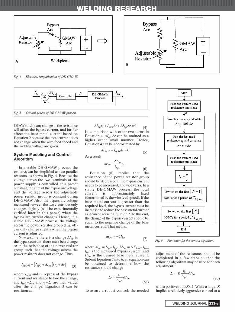
Fig. 6 — Flowchart for the control algorithm.
Li 8 07layout:Layout 1 8/6/07 5:01 PM Page 233
WELDING RESEARCH
AUGUST 2007, VOL. 86-s234
fast adjustment speed, the control of thebase metal current that determines thebase metal heat input may not require anextraordinary adjustment speed. It wasfound that K = 0.6 is fast enough.
The number of IGBTs in ON status inthe resistor combination can thus becalculated
(9)
Hence, the control system shown in Fig. 5can determine how the power resistorgroup needs to be changed to achieve thedesired base metal current.
Implementation of ControlAlgorithm
An implementation method has beenproposed to execute the controlalgorithm. First, the measurement of thebase metal current is compared with itsdesired value and Equation 8b is used tocalculate the required bypass resistancechange Δr. Second, the new resistance iscalculated as r=r0+Δr. Third, a newresistor combination can be determinedsuch that N = R/r. Finally, the first NIGBTs are switched to ON to obtain therequired bypass resistance.
When N is not an integer, theresistance r=R/N is obtained using twodifferent combinations: r1 = R/⎣N⎦ and r2= R/⎣N+1⎦, where ⎣•⎦ is an operator toreturn the integer part of N, and obviously⎣N+1⎦ = ⎣N⎦ + 1. For example, when N isequal to 2.3, this operation will return 2such that ⎣N⎦ = 2 and ⎣N+1⎦ = 3. Denote Tas the control period, which is 0.05 s. Thecontrol system will first output the resistorcombination for r2 = R/⎣N+1⎦ for a periodof TR/⎣N+1⎦ and then output the resistorcombination for r1 = R/⎣N⎦ for a period ofTR/⎣N⎦, where TR/⎣N+1⎦ + TR/⎣N⎦=Τ. To make
sure the average resistance during theperiod T is r = R/N, these two periods arecalculated as below
(10)
(11)and their ratio is
(12)
If N is an integer, Equations 10 and 11return TR/⎣N+1⎦ = 0 and TR/⎣N⎦ = T. Thus, aninteger N is a special case to Equations10–12. In the control algorithm, it is notnecessary to distinguish an integer N ornoninteger N.
Now take N = 2.3 as an instance. Onecan obtain the following results: ⎣Ν⎦ = 2,⎣N+1⎦ = 3, TR/3 = 0.3913⋅ T, and TR/2 =0.6087 ⋅ T. In the following control period T,the IGBTs associated with the first threeresistors will be ON for 39.13% of theperiod and the IGBTs with the first tworesistors will be ON for the rest (60.87%) ofthe period. The average resistance in thisperiod can be verified as 0.6087 × R/2+0.3913 × R/3 = R/2.3, which is the neededresistance for the power resistor group.
The flowchart shown in Fig. 6demonstrates the control algorithmimplemented in Matlab Simulink.
Experimental Results and Discussion
Experimental Setup
A complete DE-GMAW system wasset up with a CV power supply, a GMAWgun, a water-cooled GTAW torch, andfour 0.1-ohm power resistors controlled byfour IGBTs. The tungsten electrode,
protected by a water cooling system, had adiameter of 3.2 mm (1⁄8 in.). Both thewelding gun and torch were shielded withpure argon. The gas flow rates for GMAWgun and GTAW torch were 16.5 L/min (35ft3/h) and 7.1 L/min (15 ft3/h),respectively. The following parametersillustrated in Fig. 2 were used todetermine the geometrical relationshipbetween the GMAW gun and GTAWtorch and the workpiece: the distancefrom the GMAW contact tube to theworkpiece (d1), the distance from thebypass electrode to the workpiece (d2), thedistance between the bypass electrode andthe electrode wire (d3), and the anglebetween the electrode wire and thetungsten electrode (θ). These threedistances d1, d2, and d3 were set at 20, 5,and 4 mm, respectively. The GTAW torchwas placed ahead of the GMAW gun withan angle of 60 deg and moved from rightto left in a push mode. Experiments wereperformed on mild steel plates measuring50 × 120 × 2 mm. The low-carbon wireER70S-6 with a diameter of 1.2 mm (0.045in.) was used. The welding voltage was 35V. The power resistor group consisted offour individual power resistors, and eachhad a resistance of 0.1 ohm. Two currentsensors were used to detect the base metalcurrent and the bypass current. Thecontrol algorithm was implemented withMatLab Simulink.
In all the experiments, the base metalcurrent was sampled at 1000 Hz, and 25samples were used to calculate an averagebase metal current. The resistance of thepower resistor group was calculated each0.025 second and the digital control rate wasthus 40 Hz.
Experimental Results
Total Current Relationship with Bypass Arc
The basic idea of DE-GMAW was
T
T
N N N
N
R N
R N
/
/
+⎢⎣ ⎥⎦
⎢⎣ ⎥⎦=
+⎢⎣ ⎥⎦ − ⎢⎣ ⎥⎦( )+⎢⎣ ⎥⎦ −
1 1
1 NN N( ) ⎢⎣ ⎥⎦
TN N N
NTR N/ ⎢⎣ ⎥⎦ =
+⎢⎣ ⎥⎦ −( ) ⎢⎣ ⎥⎦1
TN N N
NTR N/ +⎢⎣ ⎥⎦ =
+⎢⎣ ⎥⎦ − ⎢⎣ ⎥⎦( )1
1
NR
r r=
+0 Δ
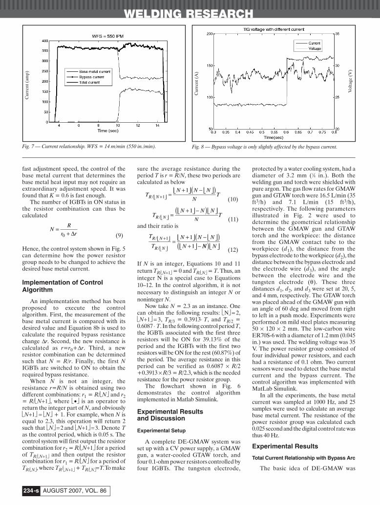
Fig. 7 — Current relationship. WFS = 14 m/min (550 in./min). Fig. 8 — Bypass voltage is only slightly affected by the bypass current.
Cur
rent
(A
)
Vol
tage
(V
)
Cur
rent
(am
p)
Li 8 07layout:Layout 1 8/6/07 5:01 PM Page 234
WELDING RESEARCH
-s235WELDING JOURNAL
based on Equation 2, which assumes thatwith given wire feed speed and givenwelding voltage, the total current is not orjust slightly affected because of the bypassarc. Thus, the base metal current can beadjusted by adjusting the bypass current.Experiments have proved thisassumption. The plot in Fig. 7 illustratesthe relationship between the threecurrents. As it can be seen, the totalcurrent, which is equal to the sum of thebase metal current and bypass current, isonly slightly changed because of thebypass arc. Considering a GMAWprocess, this slight change is common andacceptable in GMAW process because thepower supply will automatically adjust thetotal current to maintain a constantvoltage. This assumption is also verified inother experiments.
Voltage Changes Slightly across the Power Resistor Group
Experiments have been done to verifyanother assumption: the bypass arcvoltage is almost independent of thebypass current. To this end, the voltagebetween the two electrodes (the GMAWgun and the bypass GTAW torch) wasmonitored. As shown in Fig. 8, this voltageis only slightly changed with a mean valueof 27.5 V and a standard deviation of 2.2V while there is a very large change in thebypass current. This voltage is thedifference between the preset GMAWvoltage and the voltage across the powerresistors. With a constant GMAW voltage,it can be concluded that the voltage acrossthe adjustable power resistors only slightlychanges with the bypass current.
Bypass Current Has Wide Range of Adjustment
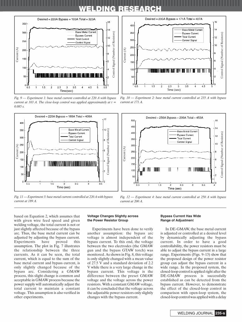
In DE-GMAW, the base metal currentis adjusted or controlled at a desired levelby dynamically adjusting the bypasscurrent. In order to have a goodcontrollability, the power resistors must beable to adjust the bypass current in a largerange. Experiments (Figs. 9–13) show thatthe proposed design of the power resistorgroup can adjust the bypass current in awide range. In the proposed system, theclosed-loop control is applied right after theDE-GMAW process is successfullyestablished as can be detected from thebypass current. However, to demonstratethe effect of the closed-loop control incomparison with open-loop system, theclosed-loop control was applied with a delay
Fig. 9 — Experiment 1: base metal current controlled at 220 A with bypasscurrent at 103 A. The close-loop control was applied approximately at t =0.085 s.
Fig. 11 — Experiment 3: base metal current controlled at 220 A with bypasscurrent at 189 A.
Fig. 12 — Experiment 4: base metal current controlled at 250 A with bypasscurrent at 200 A.
Fig. 10 — Experiment 2: base metal current controlled at 235 A with bypasscurrent at 171 A.
Cur
rent
(A
)C
urre
nt (
A)
Cur
rent
(A
)C
urre
nt (
A)
Con
trol
Sig
nal (
Num
ber
of R
esis
tors
)
Con
trol
Sig
nal (
Num
ber
of R
esis
tors
)
Con
trol
Sig
nal (
Num
ber
of R
esis
tors
)C
ontr
ol S
igna
l (N
umbe
r of
Res
isto
rs)
Li 8 07layout:Layout 1 8/6/07 5:02 PM Page 235
WELDING RESEARCH
-s236
in Experiment 1 after the DE-GMAWprocess was successfully established.
In Experiment 1, shown in Fig. 9, thetotal current was 323 A (average over theexperiment period), but the base metalcurrent needed to be controlled at 220 A.Based on the DE-GMAW design, theextra 103 A current must flow back to thepower supply through the bypass arc. Thatmeans the bypass current is 103 A.(Because the total current reducedgradually, the bypass current should alsoreduce gradually.) To that end, the controlsystem outputs a control signal between 2and 3. Here the control signal is thenumber of IGBTs in ON status or howmany individual power resistors combinedto obtain the required resistance. As canbe seen in the figure, the base metalcurrent has been successfully controlled atits desired level 220 A. However, beforethe closed-loop control was appliedapproximately at t = 0.85 s, the base metalcurrent was below the desired level.Moreover, the bypass current actuallyincreased so that the base metal currenteven decreased after approximaley t = 0.7s. After the closed-loop control wasapplied approximately at t = 0.85 s, theincrease in the bypass current was stoppedso that the base metal current started to
increase. The effect of the closed-loopcontrol is thus clearly seen.
In Experiment 2 (Fig. 10), the totalcurrent was increased to 407 A, but thebase metal current needed to becontrolled at 235 A. To this end, a bypasscurrent of 171 A was applied by adjustingthe power resistors. (Here the totalcurrent and the bypass current are theaverage of the measured values, so theirdifference should be very close to thedesired base metal current, but sometimesnot equal to the desired value.) As can beseen, in the beginning of the experiment,the base metal current was higher than thedesired value, thus the control algorithmtried to draw more current to the bypassloop by minimizing the bypass resistanceusing all parallel resistors. As a result, thebase metal current rapidly reached itsdesired value. To maintain this level, thecontrol signal then fell into the range of 3to 4. However, in Experiment 1, thecontrol signal was from 2 to 3. Itsresistance was higher so that its bypasscurrent was lower at 103 A.
In Experiment 3, shown in Fig. 11, thedesired base metal current was still 220 A,but the total current was increased to 409 A.In the beginning of the experiment, the basemetal current was significantly lower than
the desired value. However, the controlalgorithm rapidly reduced the control signalto increase the resistance of the bypass loop.As a result, the base metal current quicklyreached its desired value at approximately t= 0.5 s. Because of the quick actions, a smallovershoot occurred in the base metalcurrent. However, the control algorithmimmediately increased the control signal toreduce the resistance of the bypass loop.After approximately 0.2 s (approximately att = 0.7 s), the base metal current was settledat its desired value.
In Experiment 4, illustrated in Fig. 12,the bypass current was 200 A, and the totalcurrent was 453 A. This resulted in a basemetal current of 253 A (mean value),which is very close to the desired basemetal current. It can be seen that thecontrol signal is almost 4. That means allthe resistors are parallel used to obtain abypass current as high as 200 A.
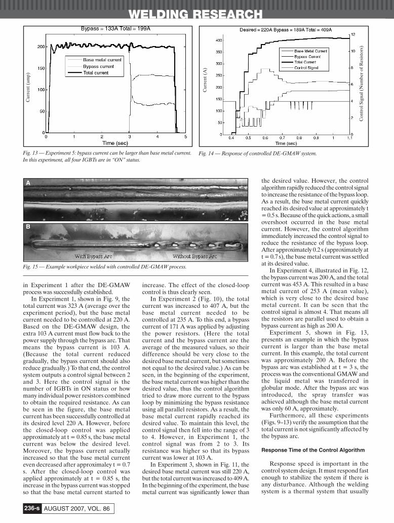
Experiment 5, shown in Fig. 13,presents an example in which the bypasscurrent is larger than the base metalcurrent. In this example, the total currentwas approximately 200 A. Before thebypass arc was established at t = 3 s, theprocess was the conventional GMAW andthe liquid metal was transferred inglobular mode. After the bypass arc wasintroduced, the spray transfer wasachieved although the base metal currentwas only 60 A, approximately.
Furthermore, all these experiments(Figs. 9–13) verify the assumption that thetotal current is not significantly affected bythe bypass arc.
Response Time of the Control Algorithm
Response speed is important in thecontrol system design. It must respond fastenough to stabilize the system if there isany disturbance. Although the weldingsystem is a thermal system that usually
Fig. 13 — Experiment 5: bypass current can be larger than base metal current.In this experiment, all four IGBTs are in “ON” status.
Fig. 14 — Response of controlled DE-GMAW system.
Fig. 15 — Example workpiece welded with controlled DE-GMAW process.
A
B
AUGUST 2007, VOL. 86
Cur
rent
(am
p)
Cur
rent
(A
)
Con
trol
Sig
nal (
Num
ber
of R
esis
tors
)
Li 8 07layout:Layout 1 8/6/07 5:02 PM Page 236
WELDING RESEARCH
-s237WELDING JOURNAL
responds slowly, the workpiece may bemelted through if the control system cannot respond fast enough. Figure 14 showsthat it takes about 0.4 s for the controlledDE-GMAW system to completely settledown. This settling time appears fastenough for the DE-GMAW process.
Bypass Arc Decreases the Base MetalHeat Input
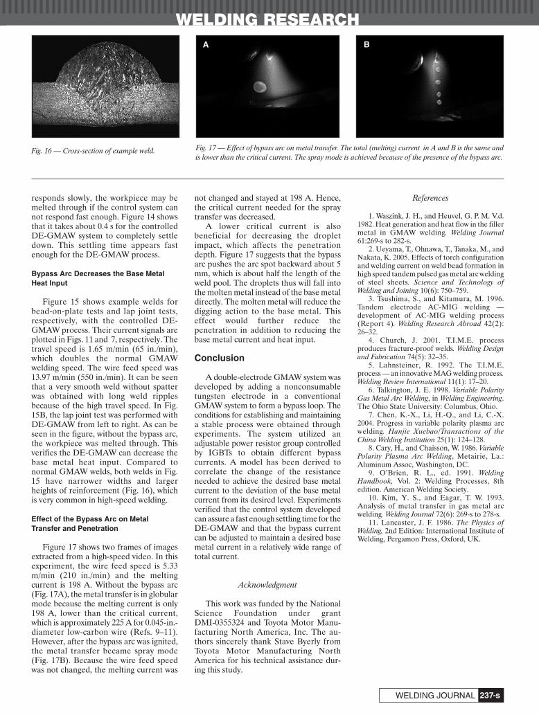
Figure 15 shows example welds forbead-on-plate tests and lap joint tests,respectively, with the controlled DE-GMAW process. Their current signals areplotted in Figs. 11 and 7, respectively. Thetravel speed is 1.65 m/min (65 in./min),which doubles the normal GMAWwelding speed. The wire feed speed was13.97 m/min (550 in./min). It can be seenthat a very smooth weld without spatterwas obtained with long weld ripplesbecause of the high travel speed. In Fig.15B, the lap joint test was performed withDE-GMAW from left to right. As can beseen in the figure, without the bypass arc,the workpiece was melted through. Thisverifies the DE-GMAW can decrease thebase metal heat input. Compared tonormal GMAW welds, both welds in Fig.15 have narrower widths and largerheights of reinforcement (Fig. 16), whichis very common in high-speed welding.
Effect of the Bypass Arc on MetalTransfer and Penetration
Figure 17 shows two frames of imagesextracted from a high-speed video. In thisexperiment, the wire feed speed is 5.33m/min (210 in./min) and the meltingcurrent is 198 A. Without the bypass arc(Fig. 17A), the metal transfer is in globularmode because the melting current is only198 A, lower than the critical current,which is approximately 225 A for 0.045-in.-diameter low-carbon wire (Refs. 9–11).However, after the bypass arc was ignited,the metal transfer became spray mode(Fig. 17B). Because the wire feed speedwas not changed, the melting current was
not changed and stayed at 198 A. Hence,the critical current needed for the spraytransfer was decreased.
A lower critical current is alsobeneficial for decreasing the dropletimpact, which affects the penetrationdepth. Figure 17 suggests that the bypassarc pushes the arc spot backward about 5mm, which is about half the length of theweld pool. The droplets thus will fall intothe molten metal instead of the base metaldirectly. The molten metal will reduce thedigging action to the base metal. Thiseffect would further reduce thepenetration in addition to reducing thebase metal current and heat input.
Conclusion
A double-electrode GMAW system wasdeveloped by adding a nonconsumabletungsten electrode in a conventionalGMAW system to form a bypass loop. Theconditions for establishing and maintaininga stable process were obtained throughexperiments. The system utilized anadjustable power resistor group controlledby IGBTs to obtain different bypasscurrents. A model has been derived tocorrelate the change of the resistanceneeded to achieve the desired base metalcurrent to the deviation of the base metalcurrent from its desired level. Experimentsverified that the control system developedcan assure a fast enough settling time for theDE-GMAW and that the bypass currentcan be adjusted to maintain a desired basemetal current in a relatively wide range oftotal current.
Acknowledgment
This work was funded by the NationalScience Foundation under grant DMI-0355324 and Toyota Motor Manu-facturing North America, Inc. The au-thors sincerely thank Stave Byerly fromToyota Motor Manufacturing NorthAmerica for his technical assistance dur-ing this study.
References
1. Waszink, J. H., and Heuvel, G. P. M. V.d.1982. Heat generation and heat flow in the fillermetal in GMAW welding. Welding Journal61:269-s to 282-s.
2. Ueyama, T., Ohnawa, T., Tanaka, M., andNakata, K. 2005. Effects of torch configurationand welding current on weld bead formation inhigh speed tandem pulsed gas metal arc weldingof steel sheets. Science and Technology ofWelding and Joining 10(6): 750–759.
3. Tsushima, S., and Kitamura, M. 1996.Tandem electrode AC-MIG welding —development of AC-MIG welding process(Report 4). Welding Research Abroad 42(2):26–32.
4. Church, J. 2001. T.I.M.E. processproduces fracture-proof welds. Welding Designand Fabrication 74(5): 32–35.
5. Lahnsteiner, R. 1992. The T.I.M.E.process — an innovative MAG welding process.Welding Review International 11(1): 17–20.
6. Talkington, J. E. 1998. Variable PolarityGas Metal Arc Welding, in Welding Engineering.The Ohio State University: Columbus, Ohio.
7. Chen, K.-X., Li, H.-Q., and Li, C.-X.2004. Progress in variable polarity plasma arcwelding. Hanjie Xuebao/Transactions of theChina Welding Institution 25(1): 124–128.
8. Cary, H., and Chaisson, W. 1986. VariablePolarity Plasma Arc Welding, Metairie, La.:Aluminum Assoc, Washington, DC.
9. O’Brien, R. L., ed. 1991. WeldingHandbook, Vol. 2: Welding Processes, 8thedition. American Welding Society.
10. Kim, Y. S., and Eagar, T. W. 1993.Analysis of metal transfer in gas metal arcwelding. Welding Journal 72(6): 269-s to 278-s.
11. Lancaster, J. F. 1986. The Physics ofWelding, 2nd Edition: International Institute ofWelding, Pergamon Press, Oxford, UK.
Fig. 16 — Cross-section of example weld. Fig. 17 — Effect of bypass arc on metal transfer. The total (melting) current in A and B is the same andis lower than the critical current. The spray mode is achieved because of the presence of the bypass arc.
A B
Li 8 07layout:Layout 1 8/6/07 5:02 PM Page 237