Embed Size (px)
Citation preview

welight
All rights reserved © 2013 welight 1(7) Subject to change without notice. www.ljuskontroll.com
W ±0,3
Highlights
Ready-to-connect flexible LED-tape for professional lighting applications
High Output version with up to 1500 lumen per meter
Excellent white color consistency McAdams SDCM ≤5
High color rendering index CRI > 80
Perfect for general lighting, e.g. slim linear & pendant luminaires.
Reflective white copper PCB for optimal system efficiency
High quality adhesive 3M-tape on backside for easy mounting on cooling profile
Long lifetime: L70 = 50.000h
Applications
General Lighting
Office Lighting
Food Lighting
Accent Lighting
Electrical Properties
Supplied with constant voltage 24 VDC
Connect up to 5 meters in series
Optimized for high resolution dimming 0,1-100% using Tridonic and feno digital drivers controlled via switchDIM, DSI, DALI or DMX.
Standards
page 2
Accessories/Options
Aluminum profiles for linear and corner applications
Wide variety of lenses and covers 15°/30°/60°/120°
Fixed or adjustable mounting brackets
Solder-free connectors and bridges
Large selection of drivers and control systems to fit every need and application
page 5
Type Article Code Supply Voltage
(VDC)
Color
(K)
Photometric
Code Typ. Data per meter Pitch
Distance (P)
Cutting Length (C)
LxWxH (mm)
Operating temp (°C)
Luminous flux (lm)
Current (mA)
Power (W)
LED quantity
LEDtape 830 1500 HO W1002-83002460751 24 3000 830 / 559 1440 1000 24 75 13,3 mm 80 mm 5040x10x2 -20 °C +50 °C
LEDtape 840 1500 HO W1002-84002460751 24 4000 840 / 559 1510 1000 24 75 13,3 mm 80 mm 5040x10x2 -20 °C +50 °C
All values for ta = 25 °C
Tolerance range for electrical and optical data ±10%
Exceeding the maximum operating voltage leads to an overload on the tape. This may result in a significant reduction in lifetime or even destruction of the tape. Tolerance range for the supply voltage 24V: +2V / -0V
According to IEC 62717
LEDtape 1500 High Output
L
C
P
welight
All rights reserved © 2013 welight 2(7) Subject to change without notice. www.ljuskontroll.com
Standards
EN 55015:2006 + A1:2007 + A2:2009 EN 61000-3-2:2006 + A1:2009 + A2:2009 EN 61000-3-3:2008 EN 61547:2009 EN 62471:2008 IEC/PAS 62717
Thermal behavior
Storage Temperature -30/+60 °C
Operating Temperature -20/+50 °C
Tc max 65 °C
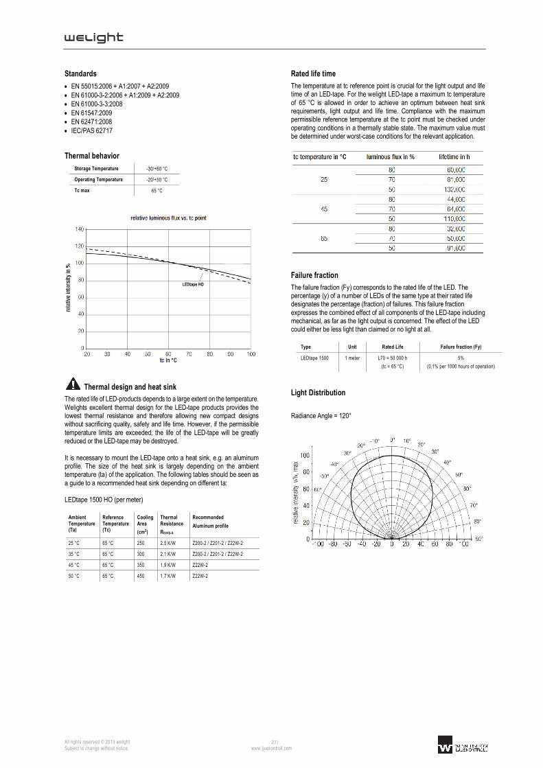
Thermal design and heat sink
The rated life of LED-products depends to a large extent on the temperature. Welights excellent thermal design for the LED-tape products provides the lowest thermal resistance and therefore allowing new compact designs without sacrificing quality, safety and life time. However, if the permissible temperature limits are exceeded, the life of the LED-tape will be greatly reduced or the LED-tape may be destroyed. It is necessary to mount the LED-tape onto a heat sink, e.g. an aluminum profile. The size of the heat sink is largely depending on the ambient temperature (ta) of the application. The following tables should be seen as a guide to a recommended heat sink depending on different ta: LEDtape 1500 HO (per meter)
Ambient Temperature (Ta)
Reference Temperature (Tc)
Cooling Area
(cm2)
Thermal Resistance
RthHS-A
Recommended
Aluminum profile
25 °C 65 °C 250 2,5 K/W Z200-2 / Z201-2 / Z22W-2
35 °C 65 °C 300 2,1 K/W Z200-2 / Z201-2 / Z22W-2
45 °C 65 °C 350 1,9 K/W Z22W-2
50 °C 65 °C 450 1,7 K/W Z22W-2
Rated life time
The temperature at tc reference point is crucial for the light output and life time of an LED-tape. For the welight LED-tape a maximum tc temperature of 65 °C is allowed in order to achieve an optimum between heat sink requirements, light output and life time. Compliance with the maximum permissible reference temperature at the tc point must be checked under operating conditions in a thermally stable state. The maximum value must be determined under worst-case conditions for the relevant application.
Failure fraction
The failure fraction (Fy) corresponds to the rated life of the LED. The percentage (y) of a number of LEDs of the same type at their rated life designates the percentage (fraction) of failures. This failure fraction expresses the combined effect of all components of the LED-tape including mechanical, as far as the light output is concerned. The effect of the LED could either be less light than claimed or no light at all.
Type Unit Rated Life Failure fraction (Fy)
LEDtape 1500 1 meter L70 = 50 000 h
(tc = 65 °C)
5%
(0,1% per 1000 hours of operation)
Light Distribution
Radiance Angle = 120°

welight
All rights reserved © 2013 welight 3(7) Subject to change without notice. www.ljuskontroll.com
Chromaticity coordinates and tolerances according to CIE 1931
Color Photometric Code
3000 K 830 / 559
4000 K 840 / 559
The specified color coordinates are measured by a current impulse with nominal values of module after a settling time of 100 msec. The ambient temperature of the measurement is ta = 25 °C. The measurement tolerance of the color coordinates are ± 0.01.
welight
All rights reserved © 2013 welight 4(7) Subject to change without notice. www.ljuskontroll.com
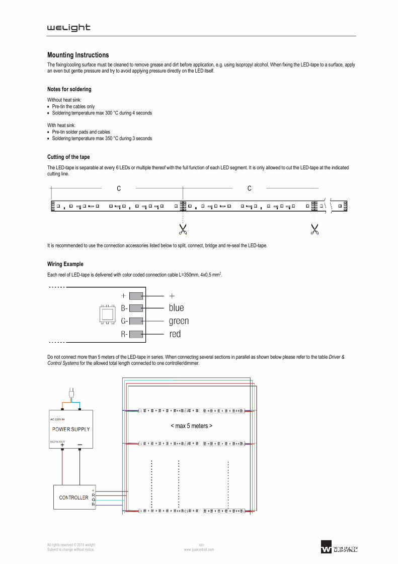
Mounting Instructions The fixing/cooling surface must be cleaned to remove grease and dirt before application, e.g. using Isopropyl alcohol. When fixing the LED-tape to a surface, apply an even but gentle pressure and try to avoid applying pressure directly on the LED itself.
Notes for soldering
Without heat sink: Pre-tin the cables only Soldering temperature max 300 °C during 4 seconds With heat sink: Pre-tin solder pads and cables Soldering temperature max 350 °C during 3 seconds
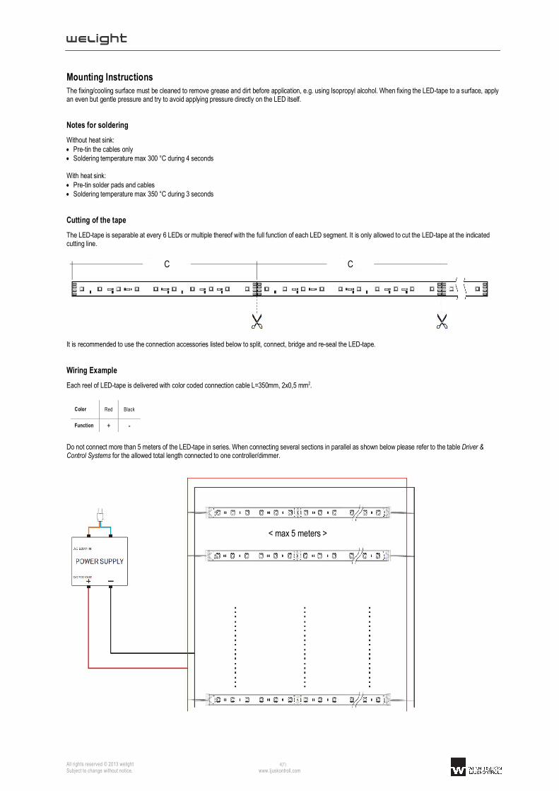
Cutting of the tape
The LED-tape is separable at every 6 LEDs or multiple thereof with the full function of each LED segment. It is only allowed to cut the LED-tape at the indicated cutting line.
It is recommended to use the connection accessories listed below to split, connect, bridge and re-seal the LED-tape.
Wiring Example
Each reel of LED-tape is delivered with color coded connection cable L=350mm, 2x0,5 mm2.
Color Red Black
Function + -
Do not connect more than 5 meters of the LED-tape in series. When connecting several sections in parallel as shown below please refer to the table Driver & Control Systems for the allowed total length connected to one controller/dimmer.
C C
< max 5 meters >
welight
All rights reserved © 2013 welight 5(7) Subject to change without notice. www.ljuskontroll.com
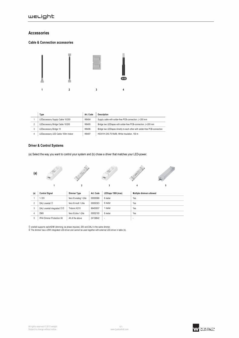
Accessories
Cable & Connection accessories
1 2 3 4
Type Art. Code Description
1 LEDaccessory Supply Cable 10/200 W8404 Supply cable with solder-free PCB-connection, L=200 mm
2 LEDaccessory Bridge Cable 10/200 W8405 Bridge two LEDtapes with solder-free PCB-connection, L=200 mm
3 LEDaccessory Bridge 10 W8406 Bridge two LEDtapes directly to each other with solder-free PCB-connection
4 LEDaccessory LED Cable 100m Indoor W8407 H03VVH 2X0.75 Rd/Bl, White Insulation, 100 m
Driver & Control Systems
(a) Select the way you want to control your system and (b) chose a driver that matches your LED-power.
(a)
1 2 3 4 5
(a) Control Signal Dimmer Type Art. Code LEDtape 1500 (max) Multiple dimmers allowed
1 1-10V feno fd analog 1-24e 00000066 6 meter Yes
2 DALI one4all feno fd multi 1-24e 00000303 6 meter Yes
3 DALI one4all integrated Tridonic K210 86455937 1 meter Yes
4 DMX feno fd dmx 1-24e 00002100 6 meter Yes
5 IP44 Dimmer Protection Kit All of the above 24138842 - -
one4all supports switchDIM (dimming via phase impulse), DSI and DALI in the same dimmer.
The dimmer has a 25W integrated LED-driver and cannot be used together with external LED-driver in table (b).

welight
All rights reserved © 2013 welight 6(7) Subject to change without notice. www.ljuskontroll.com
(b)
1 2 3 4 5
(b) Driver IP20 Art. Code IP67 Art. Code
1 Tridonic LCU 025/24 86453418 -
2 Tridonic LCU 035/24 24166320 -
3 Tridonic LCU 060/24 24166324 24166326
4 Tridonic LCU 100/24 24166328 22185185
5 Tridonic LCU 0150/24 24166333 22185186
LED-drivers <25 W available on request. Please contact us at [email protected] for information about suitable end-user control interfaces, e.g. touch panels, color mixing software, potentiometers, push-buttons, etc.
Aluminum Profile Systems
Start by selecting an aluminum profile (a) and a suitable lens cover (b) and then add optional accessories (c).
(a)
1 2 3
Optional accessories
(a) Type Art. Code L (mm) W (mm) H (mm) W (mm) incl. lens cover
H (mm) incl. lens cover
Application Lens Cover End Cap Fixed Mount Adjustable Mount
1 Z200-2 24166148 2000 18 9 21 16 Corner
2 Z201-2 24166149 2000 18 9 21 16 Linear Slim
3 Z22W-2 24166150 2000 18 16 21 24 Linear
(b)
1 2 3 4 5
Profile
(b) Type Art. Code L (mm) Typ. application Z200-2 Z201-2 Z22W-2
1 15° 24166409 2000 Wall wash
2 30° 24166410 2000 Wall wash
3 60° 24166411 2000 Shelf
4 120° 24138737 2000 Accent
5 120° opal 24138736 2000 Lines

welight
All rights reserved © 2013 welight 7(7) Subject to change without notice. www.ljuskontroll.com
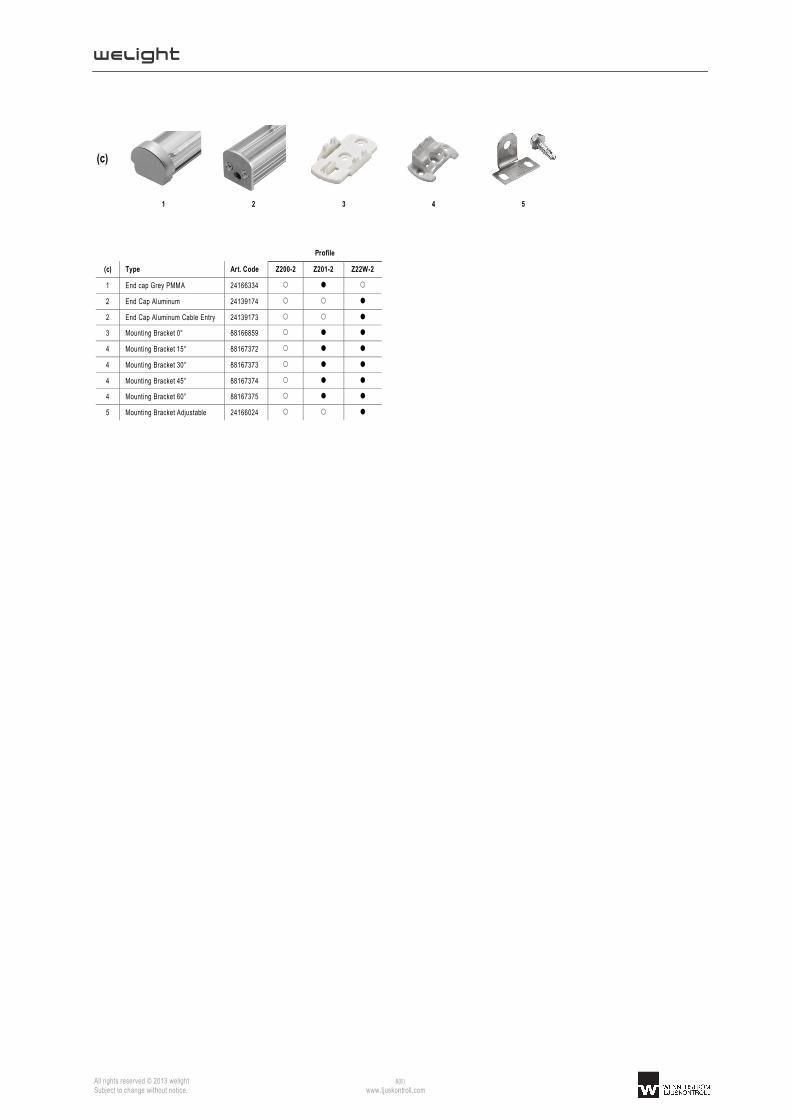
(c)
1 2 3 4 5
Profile
(c) Type Art. Code Z200-2 Z201-2 Z22W-2
1 End cap Grey PMMA 24166334
2 End Cap Aluminum 24139174
2 End Cap Aluminum Cable Entry 24139173
3 Mounting Bracket 0° 88166859
4 Mounting Bracket 15° 88167372
4 Mounting Bracket 30° 88167373
4 Mounting Bracket 45° 88167374
4 Mounting Bracket 60° 88167375
5 Mounting Bracket Adjustable 24166024

welight
All rights reserved © 2013 welight 1(8) Subject to change without notice. www.ljuskontroll.com
W ±0,3
Highlights
Ready-to-connect flexible LED-tape for professional lighting applications
High color rendering index CRI > 90
GOLD perfect for food lighting of fresh goods, e.g. salads, pastry, bread etc.
GOLD+ Ideal for hospitality, wellness and domestic environments where an incandescent-like light quality is needed
Reflective white copper PCB for optimal system efficiency
High quality adhesive 3M-tape on backside for easy mounting on common surfaces (only IP20)
Long lifetime: L70 = 50.000h
Applications
Food Lighting
Shelf Lighting
Accent Lighting
Ambient Lighting
Electrical Properties
Supplied with constant voltage 24 VDC
Connect up to 5 meters in series
Optimized for high resolution dimming 0,1-100% using Tridonic and feno digital drivers controlled via switchDIM, DSI, DALI or DMX.
Standards
page 2
Accessories/Options
Aluminum profiles for linear and corner applications
Wide variety of lenses and covers 15°/30°/60°/120°
Fixed or adjustable mounting brackets
Solder-free connectors and bridges
Large selection of drivers and control systems to fit every need and application
page 6
Type Article Code Supply Voltage
(VDC)
Color
(K)
Photometric
Code Typ. Data per meter Pitch
Distance (P)
Cutting Length (C)
LxWxH (mm)
Operating temp (°C)
Luminous flux (lm)
Current (mA)
Power (W)
LED quantity
LEDtape GOLD 600 W1001-92702450601 24 2700 927 / 559 563 560 14,4 60 16,7 mm 100 mm 5000x10x2 -20 °C
+50 °C
LEDtape GOLD 600 IP65 W1101-92702450601 24 2700 927 / 559 525 560 14,4 60 16,7 mm 100 mm 5000x14x6 -20 °C
+35 °C
LEDtape GOLD+ 600 W1001-92402450601 24 2400 924 / 559 543 560 14,4 60 16,7 mm 100 mm 5000x10x2 -20 °C +50 °C
LEDtape GOLD+ 600 IP65 W1101-92402450601 24 2400 924 / 559 505 560 14,4 60 16,7 mm 100 mm 5000x14x6 -20 °C +35 °C
All values for ta = 25 °C
Tolerance range for electrical and optical data ±10%
Exceeding the maximum operating voltage leads to an overload on the tape. This may result in a significant reduction in lifetime or even destruction of the tape. Tolerance range for the supply voltage 24V: +2V / -0V
Self-cooling at ta ≤ 35 °C
According to IEC 62717
IP20/IP65
L
C
LEDtape GOLD / GOLD+
P
tc

welight
All rights reserved © 2013 welight 2(8) Subject to change without notice. www.ljuskontroll.com
Standards
EN 55015:2006 + A1:2007 + A2:2009 EN 61000-3-2:2006 + A1:2009 + A2:2009 EN 61000-3-3:2008 EN 61547:2009 EN 62471:2008 IEC/PAS 62717
Thermal behavior
Storage Temperature -30/+60 °C
Operating Temperature -20/+50 °C
Tc max 65 °C
Thermal design and heat sink
The rated life of LED-products depends to a large extent on the temperature. Welights excellent thermal design for the LED-tape products provides the lowest thermal resistance and therefore allowing new compact designs without sacrificing quality, safety and life time. However, if the permissible temperature limits are exceeded, the life of the LED-tape will be greatly reduced or the LED-tape may be destroyed. It is often recommended to mount the LED-tape onto a heat sink, e.g. an aluminum profile. The need for a heat sink is largely depending on the ambient temperature (ta) of the application. The following tables should be seen as a guide to a recommended heat sink depending on different ta for the LEDtape GOLD/GOLD+: LEDtape GOLD/GOLD+ (per meter)
Ambient Temperature (Ta)
Reference Temperature (Tc)
Cooling Area
(cm2)
Thermal Resistance
RthHS-A
Recommended
Aluminum profile
25 °C 65 °C Self-cooling Self-cooling Optional
35 °C 65 °C Self-cooling Self-cooling Optional
45 °C 65 °C 300 2,1 K/W Z200-2 / Z201-2 / Z22W-2
55 °C 65 °C 400 1,8 K/W Z22W-2
LEDtape GOLD/GOLD+ IP65 (per meter)
Ambient Temperature (Ta)
Reference Temperature (Tc)
Cooling Area
(cm2)
Thermal Resistance
RthHS-A
Recommended
Aluminum profile
25 °C 65 °C Self-cooling Self-cooling Optional
35 °C 65 °C Self-cooling Self-cooling Optional
45 °C Not allowed - - -
55 °C Not allowed - - -
Rated life time
The temperature at tc reference point is crucial for the light output and life time of an LED-tape. For the welight LED-tape a maximum tc temperature of 65 °C is allowed in order to achieve an optimum between heat sink requirements, light output and life time. Compliance with the maximum permissible reference temperature at the tc point must be checked under operating conditions in a thermally stable state. The maximum value must be determined under worst-case conditions for the relevant application.
Failure fraction
The failure fraction (Fy) corresponds to the rated life of the LED. The percentage (y) of a number of LEDs of the same type at their rated life designates the percentage (fraction) of failures. This failure fraction expresses the combined effect of all components of the LED-tape including mechanical, as far as the light output is concerned. The effect of the LED could either be less light than claimed or no light at all.
Type Unit Rated Life Failure fraction (Fy)
LEDtape GOLD/GOLD+
1 meter L70 = 50 000 h
(tc = 65 °C)
5%
(0,1% per 1000 hours of operation)
Light Distribution
Radiance Angle = 120°
business

welight
All rights reserved © 2013 welight 3(8) Subject to change without notice. www.ljuskontroll.com
Chromaticity coordinates and tolerances according to CIE 1931
Color Photometric Code
GOLD 2700 K 927 / 559
GOLD+ 2400 K 924 / 559
GOLD 2700 K
McAdam ellipse: 5 SDCM
GOLD+ 2400 K
McAdam ellipse: 5 SDCM
The specified color coordinates are measured by a current impulse with nominal values of module after a settling time of 100 msec. The ambient temperature of the measurement is ta = 25 °C. The measurement tolerance of the color coordinates are ± 0.01.

welight
All rights reserved © 2013 welight 4(8) Subject to change without notice. www.ljuskontroll.com
Mounting Instructions
The fixing/cooling surface must be cleaned to remove grease and dirt before application, e.g. using Isopropyl alcohol. When fixing the LED-tape to a surface, apply an even but gentle pressure and try to avoid applying pressure directly on the LED itself.
Notes for soldering
Without heat sink: Pre-tin the cables only Soldering temperature max 300 °C during 4 seconds With heat sink: Pre-tin solder pads and cables Soldering temperature max 350 °C during 3 seconds
Cutting of the tape
The LED-tape is separable at every 6 LEDs or multiple thereof with the full function of each LED segment. It is only allowed to cut the LED-tape at the indicated cutting line.
It is recommended to use the connection accessories listed below to split, connect, bridge and re-seal the LED-tape.
Wiring Example
Each reel of LED-tape is delivered with color coded connection cable L=350mm, 2x0,5 mm2.
Color Red Black
Function + -
Do not connect more than 5 meters of the LED-tape in series. When connecting several sections in parallel as shown below please refer to the table Driver & Control Systems for the allowed total length connected to one controller/dimmer.
C C
< max 5 meters >

welight
All rights reserved © 2013 welight 5(8) Subject to change without notice. www.ljuskontroll.com
welight
All rights reserved © 2013 welight 6(8) Subject to change without notice. www.ljuskontroll.com
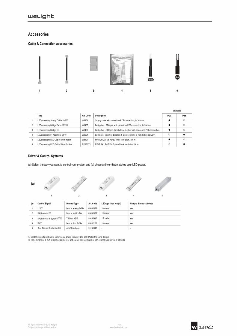
Accessories
Cable & Connection accessories
1 2 3 4 5 6
LEDtape
Type Art. Code Description IP20 IP65
1 LEDaccessory Supply Cable 10/200 W8404 Supply cable with solder-free PCB-connection, L=200 mm
2 LEDaccessory Bridge Cable 10/200 W8405 Bridge two LEDtapes with solder-free PCB-connection, L=200 mm
3 LEDaccessory Bridge 10 W8406 Bridge two LEDtapes directly to each other with solder-free PCB-connection
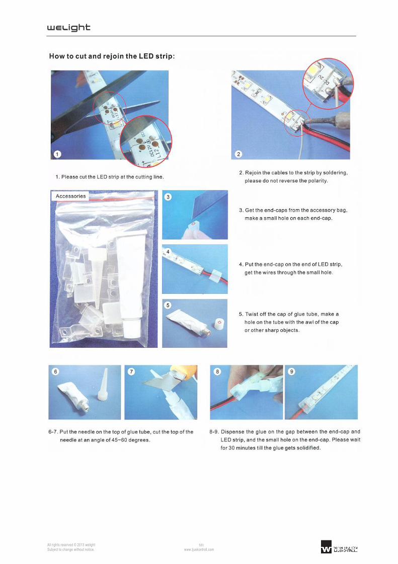
4 LEDaccessory IP Assembly Kit 10 W8901 End Caps, Mounting Brackets & Silicon (one kit is included on delivery)
5 LEDaccessory LED Cable 100m Indoor W8407 H03VVH 2X0.75 Rd/Bl, White Insulation, 100 m
5 LEDaccessory LED Cable 100m Outdoor RKKB2X1 RKKB 2X1 Rd/Bl Yd 5,8mm Black Insulation 100 m
Driver & Control Systems
(a) Select the way you want to control your system and (b) chose a driver that matches your LED-power.
(a)
1 2 3 4 5
(a) Control Signal Dimmer Type Art. Code LEDtape (max length) Multiple dimmers allowed
1 1-10V feno fd analog 1-24e 00000066 10 meter Yes
2 DALI one4all feno fd multi 1-24e 00000303 10 meter Yes
3 DALI one4all integrated Tridonic K210 86455937 1,7 meter Yes
4 DMX feno fd dmx 1-24e 00002100 10 meter Yes
5 IP44 Dimmer Protection Kit All of the above 24138842 - -
one4all supports switchDIM (dimming via phase impulse), DSI and DALI in the same dimmer. The dimmer has a 25W integrated LED-driver and cannot be used together with external LED-driver in table (b).

welight
All rights reserved © 2013 welight 7(8) Subject to change without notice. www.ljuskontroll.com
(b)
1 2 3 4 5
(b) Driver IP20 Art. Code IP67 Art. Code
1 Tridonic LCU 025/24 86453418 -
2 Tridonic LCU 035/24 24166320 -
3 Tridonic LCU 060/24 24166324 24166326
4 Tridonic LCU 100/24 24166328 22185185
5 Tridonic LCU 0150/24 24166333 22185186
LED-drivers <25 W available on request. Please contact us at [email protected] for information about suitable end-user control interfaces, e.g. touch panels, color mixing software, potentiometers, push-buttons, etc.
Aluminum Profile Systems
Start by selecting an aluminum profile (a) and a suitable lens cover (b) and then add optional accessories (c).
(a)
1 2 3
Optional accessories
(a) Type Art. Code L (mm) W (mm) H (mm) W (mm) incl. lens cover
H (mm) incl. lens cover
Application Lens Cover End Cap Fixed Mount Adjustable Mount
1 Z200-2 24166148 2000 18 9 21 16 Corner
2 Z201-2 24166149 2000 18 9 21 16 Linear Slim
3 Z22W-2 24166150 2000 18 16 21 24 Linear
(b)
1 2 3 4 5
Profile
(b) Type Art. Code L (mm) Typ. application Z200-2 Z201-2 Z22W-2
1 15° 24166409 2000 Wall wash
2 30° 24166410 2000 Wall wash
3 60° 24166411 2000 Shelf
4 120° 24138737 2000 Accent
5 120° opal 24138736 2000 Lines
welight
All rights reserved © 2013 welight 8(8) Subject to change without notice. www.ljuskontroll.com
(c)
1 2 3 4 5
Profile
(c) Type Art. Code Z200-2 Z201-2 Z22W-2
1 End cap Grey PMMA 24166334
2 End Cap Aluminum 24139174
2 End Cap Aluminum Cable Entry 24139173
3 Mounting Bracket 0° 88166859
4 Mounting Bracket 15° 88167372
4 Mounting Bracket 30° 88167373
4 Mounting Bracket 45° 88167374
4 Mounting Bracket 60° 88167375
5 Mounting Bracket Adjustable 24166024

welight
All rights reserved © 2013 welight 1(8) Subject to change without notice. www.ljuskontroll.com
W ±0,3
Highlights
Ready-to-connect flexible LED-tape for professional color mixing
Optimized Individual color calibration to generate white light from RGB LEDs
Multichip LEDs placed under the same lens to achieve high quality color mixing – no rainbow effects
Reflective white copper PCB for optimal system efficiency
High quality adhesive 3M-tape on backside for easy mounting on common surfaces (only IP20)
Available in two different lumen packages – High Efficiency (HE) and High Output (HO)
Long lifetime: L70 = 50.000h
Applications
Wall Washing effects
Accent Lighting
Edge and Injection Lighting of transparent or diffuse materials
Electrical Properties
Supplied with constant voltage 24 VDC
Connect up to 5 meters in series
Optimized for high resolution dimming 0,1-100% using Tridonic and feno digital drivers controlled via DSI, DALI or DMX.
Standards
page 2
Accessories/Options
Wide range of aluminum profiles for linear and corner applications
Wide variety of lenses and covers 15°/30°/60°/120°
Fixed or adjustable mounting brackets
Solder-free connectors and bridges
Large selection of drivers and control systems to fit every need and application
page 6
Type Article Code Supply Voltage
(VDC)
Power
(W/m)
Typ. Data per meter
Luminous flux (lm) | Current (mA) | Wavelength (nm)
LED-quantity
Pitch Distance (P)
Cutting Length (C)
Dimensions LxWxH (mm)
Operating temp
ta range (°C)
Red Green Blue Total
LEDtape RGB 500 HE W1201-RGB02450601 24 14,4 120 lm
211 mA
625 nm
240 lm
200 mA
550 nm
150 lm
189 mA
465 nm
510 lm
600 mA
-
60 per meter
16,7 mm
100 mm
5000x10x2 -20 °C / +50 °C
LEDtape RGB 500 HE IP65 W1301-RGB02450601 24 14,4 108 lm
211 mA
625 nm
216 lm
200 mA
550 nm
135 lm
189 mA
465 nm
459 lm
600 mA
-
60 per meter
16,7 mm
100 mm
5000x14x6 -20 °C / +35 °C
LEDtape RGB 900 HO W1202-RGB02450721 24 17,3 216 lm
253 mA
625 nm
432 lm
240 mA
550 nm
269 lm
227 mA
465 nm
917 lm
720 mA
-
72 per meter
13,9 mm
83,6 mm
5000x10x2 -20 °C / +50 °C
All values for ta = 25 °C
Tolerance range for electrical and optical data ±15%
Exceeding the maximum operating voltage leads to an overload on the tape. This may result in a significant reduction in lifetime or even destruction of the tape. Tolerance range for the supply voltage 24V: +2V / -0V
Self-cooling at ta ≤ 35 °C
Cooling is required. Please see separate table for heat sink requirements.
IP20/IP65 LEDtape RGB
L
C
P

welight
All rights reserved © 2013 welight 2(8) Subject to change without notice. www.ljuskontroll.com
Standards
EN 55015:2006 + A1:2007 + A2:2009 EN 61000-3-2:2006 + A1:2009 + A2:2009 EN 61000-3-3:2008 EN 61547:2009 EN 62471:2008 IEC/PAS 62717
Thermal behavior
Storage Temperature -30/+60 °C
Operating Temperature -20/+50 °C
Tc max 65 °C
Thermal design and heat sink
The rated life of LED-products depends to a large extent on the temperature. Welights excellent thermal design for the LED-tape products provides the lowest thermal resistance and therefore allowing new compact designs without sacrificing quality, safety and life time. However, if the permissible temperature limits are exceeded, the life of the LED-tape will be greatly reduced or the LED-tape may be destroyed. It is often recommended to mount the LED-tape onto a heat sink, e.g. an aluminum profile. The need for a heat sink is largely depending on the ambient temperature (ta) of the application. The following tables should be seen as a guide to a recommended heat sink depending on different ta for the LEDtape RGB: LEDtape RGB HE (per meter)
Ambient Temperature (Ta)
Reference Temperature (Tc)
Cooling Area
(cm2)
Thermal Resistance
RthHS-A
Recommended
Aluminum profile
25 °C 65 °C Self-cooling Self-cooling Optional
35 °C 65 °C Self-cooling Self-cooling Optional
45 °C 65 °C 300 2,1 K/W Z200-2 / Z201-2 / Z22W-2
55 °C 65 °C 400 1,8 K/W Z22W-2
LEDtape RGB HE IP65 (per meter)
Ambient Temperature (Ta)
Reference Temperature (Tc)
Cooling Area
(cm2)
Thermal Resistance
RthHS-A
Recommended
Aluminum profile
25 °C 65 °C Self-cooling Self-cooling Optional
35 °C 65 °C Self-cooling Self-cooling Optional
45 °C Not allowed - - -
55 °C Not allowed - - -
LEDtape RGB HO (per meter) Ambient Temperature (Ta)
Reference Temperature (Tc)
Cooling Area
(cm2)
Thermal Resistance
RthHS-A
Recommended
Aluminum profile
25 °C 65 °C 250 2,5 K/W Z200-2 / Z201-2 / Z22W-2
35 °C 65 °C 300 2,1 K/W Z200-2 / Z201-2 / Z22W-2
45 °C 65 °C 350 1,9 K/W Z22W-2
55 °C 65 °C 450 1,7 K/W Z22W-2
Rated life time
The temperature at tc reference point is crucial for the light output and life time of a LED-tape. For the welight LED-tape a maximum tc temperature of 65 °C is allowed in order to achieve an optimum between heat sink requirements, light output and life time. Compliance with the maximum permissible reference temperature at the tc point must be checked under operating conditions in a thermally stable state. The maximum value must be determined under worst-case conditions for the relevant application.
Failure fraction
The failure fraction (Fy) corresponds to the rated life of the LED. The percentage (y) of a number of LEDs of the same type at their rated life designates the percentage (fraction) of failures. This failure fraction expresses the combined effect of all components of the LED-tape including mechanical, as far as the light output is concerned. The effect of the LED could either be less light than claimed or no light at all.
Type Unit Rated Life Failure fraction (Fy)
LEDtape RGB 1 meter L70 = 50 000 h
(tc = 65 °C)
5%
(0,1% per 1000 hours of operation)
Light Distribution
Radiance Angle = 120°

welight
All rights reserved © 2013 welight 3(8) Subject to change without notice. www.ljuskontroll.com
CIE chromaticity diagram
welight
All rights reserved © 2013 welight 4(8) Subject to change without notice. www.ljuskontroll.com
Mounting Instructions The fixing/cooling surface must be cleaned to remove grease and dirt before application, e.g. using Isopropyl alcohol. When fixing the LED-tape to a surface, apply an even but gentle pressure and try to avoid applying pressure directly on the LED itself.
Notes for soldering
Without heat sink: Pre-tin the cables only Soldering temperature max 300 °C during 4 seconds With heat sink: Pre-tin solder pads and cables Soldering temperature max 350 °C during 3 seconds
Cutting of the tape
The LED-tape is separable at every 6 LEDs or multiple thereof with the full function of each LED segment. It is only allowed to cut the LED-tape at the indicated cutting line.
It is recommended to use the connection accessories listed below to split, connect, bridge and re-seal the LED-tape.
Wiring Example
Each reel of LED-tape is delivered with color coded connection cable L=350mm, 4x0,5 mm2.
Do not connect more than 5 meters of the LED-tape in series. When connecting several sections in parallel as shown below please refer to the table Driver & Control Systems for the allowed total length connected to one controller/dimmer.
C C
< max 5 meters >
welight
All rights reserved © 2013 welight 5(8) Subject to change without notice. www.ljuskontroll.com
welight
All rights reserved © 2013 welight 6(8) Subject to change without notice. www.ljuskontroll.com
Accessories
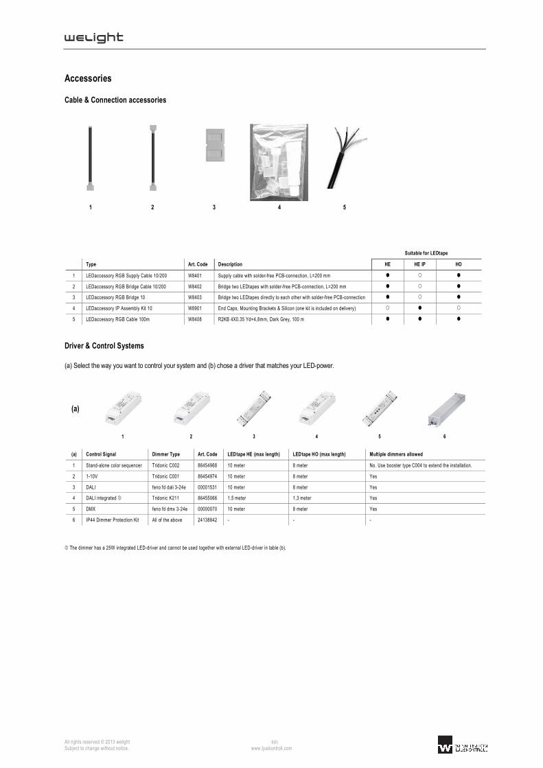
Cable & Connection accessories
1 2 3 4 5
Suitable for LEDtape
Type Art. Code Description HE HE IP HO
1 LEDaccessory RGB Supply Cable 10/200 W8401 Supply cable with solder-free PCB-connection, L=200 mm
2 LEDaccessory RGB Bridge Cable 10/200 W8402 Bridge two LEDtapes with solder-free PCB-connection, L=200 mm
3 LEDaccessory RGB Bridge 10 W8403 Bridge two LEDtapes directly to each other with solder-free PCB-connection
4 LEDaccessory IP Assembly Kit 10 W8901 End Caps, Mounting Brackets & Silicon (one kit is included on delivery)
5 LEDaccessory RGB Cable 100m W8408 R2KB 4X0.35 Yd=4,8mm, Dark Grey, 100 m
Driver & Control Systems
(a) Select the way you want to control your system and (b) chose a driver that matches your LED-power.
(a)
1 2 3 4 5 6
(a) Control Signal Dimmer Type Art. Code LEDtape HE (max length) LEDtape HO (max length) Multiple dimmers allowed
1 Stand-alone color sequencer Tridonic C002 86454968 10 meter 8 meter No. Use booster type C004 to extend the installation.
2 1-10V Tridonic C001 86454974 10 meter 8 meter Yes
3 DALI feno fd dali 3-24e 00001531 10 meter 8 meter Yes
4 DALI integrated Tridonic K211 86455066 1,5 meter 1,3 meter Yes
5 DMX feno fd dmx 3-24e 00000070 10 meter 8 meter Yes
6 IP44 Dimmer Protection Kit All of the above 24138842 - - -
The dimmer has a 25W integrated LED-driver and cannot be used together with external LED-driver in table (b).
welight
All rights reserved © 2013 welight 7(8) Subject to change without notice. www.ljuskontroll.com
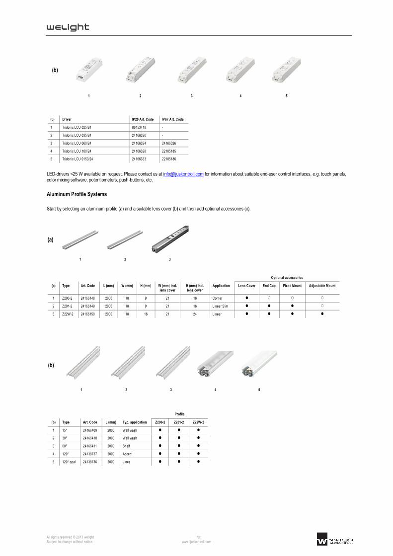
(b)
1 2 3 4 5
(b) Driver IP20 Art. Code IP67 Art. Code
1 Tridonic LCU 025/24 86453418 -
2 Tridonic LCU 035/24 24166320 -
3 Tridonic LCU 060/24 24166324 24166326
4 Tridonic LCU 100/24 24166328 22185185
5 Tridonic LCU 0150/24 24166333 22185186
LED-drivers <25 W available on request. Please contact us at [email protected] for information about suitable end-user control interfaces, e.g. touch panels, color mixing software, potentiometers, push-buttons, etc.
Aluminum Profile Systems
Start by selecting an aluminum profile (a) and a suitable lens cover (b) and then add optional accessories (c).
(a)
1 2 3
Optional accessories
(a) Type Art. Code L (mm) W (mm) H (mm) W (mm) incl. lens cover
H (mm) incl. lens cover
Application Lens Cover End Cap Fixed Mount Adjustable Mount
1 Z200-2 24166148 2000 18 9 21 16 Corner
2 Z201-2 24166149 2000 18 9 21 16 Linear Slim
3 Z22W-2 24166150 2000 18 16 21 24 Linear
(b)
1 2 3 4 5
Profile
(b) Type Art. Code L (mm) Typ. application Z200-2 Z201-2 Z22W-2
1 15° 24166409 2000 Wall wash
2 30° 24166410 2000 Wall wash
3 60° 24166411 2000 Shelf
4 120° 24138737 2000 Accent
5 120° opal 24138736 2000 Lines

welight
All rights reserved © 2013 welight 8(8) Subject to change without notice. www.ljuskontroll.com
(c)
1 2 3 4 5
Profile
(c) Type Art. Code Z200-2 Z201-2 Z22W-2
1 End cap Grey PMMA 24166334
2 End Cap Aluminum 24139174
2 End Cap Aluminum Cable Entry 24139173
3 Mounting Bracket 0° 88166859
4 Mounting Bracket 15° 88167372
4 Mounting Bracket 30° 88167373
4 Mounting Bracket 45° 88167374
4 Mounting Bracket 60° 88167375
5 Mounting Bracket Adjustable 24166024