Embed Size (px)
Citation preview
28 August 2019Footer text... 1Footer text...
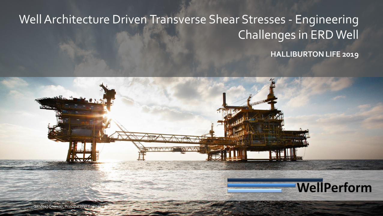
Well Architecture Driven Transverse Shear Stresses - Engineering Challenges in ERD Well
HALLIBURTON LIFE 2019
1Sandeep Dhawan, Principal Well Engineer
EXTERNAL © 2019 Halliburton. All rights reserved.
DISCLAIMER 2019
The contents of this presentation are for informational purposes only. Halliburton** makes no representation or warranty about the accuracy or suitability of the information provided in this presentation and any related materials. Nothing in this presentation constitutes professional advice or consulting services. No contractual relationship with Halliburton is established by attending or viewing this presentation. No rights to intellectual property of Halliburton are granted through this presentation. The opinions expressed in this presentation are those of the author and do not necessarily represent the views of Halliburton. **Halliburton means Halliburton Energy Services, Inc., Landmark Graphics Corporation, and their affiliates.
3
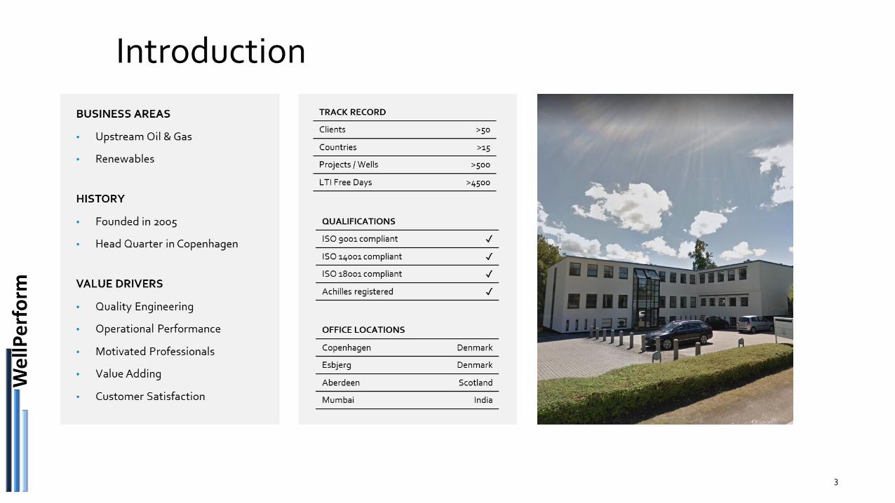
Introduction
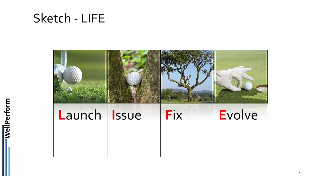
Sketch - LIFE
4
Launch Issue Fix Evolve
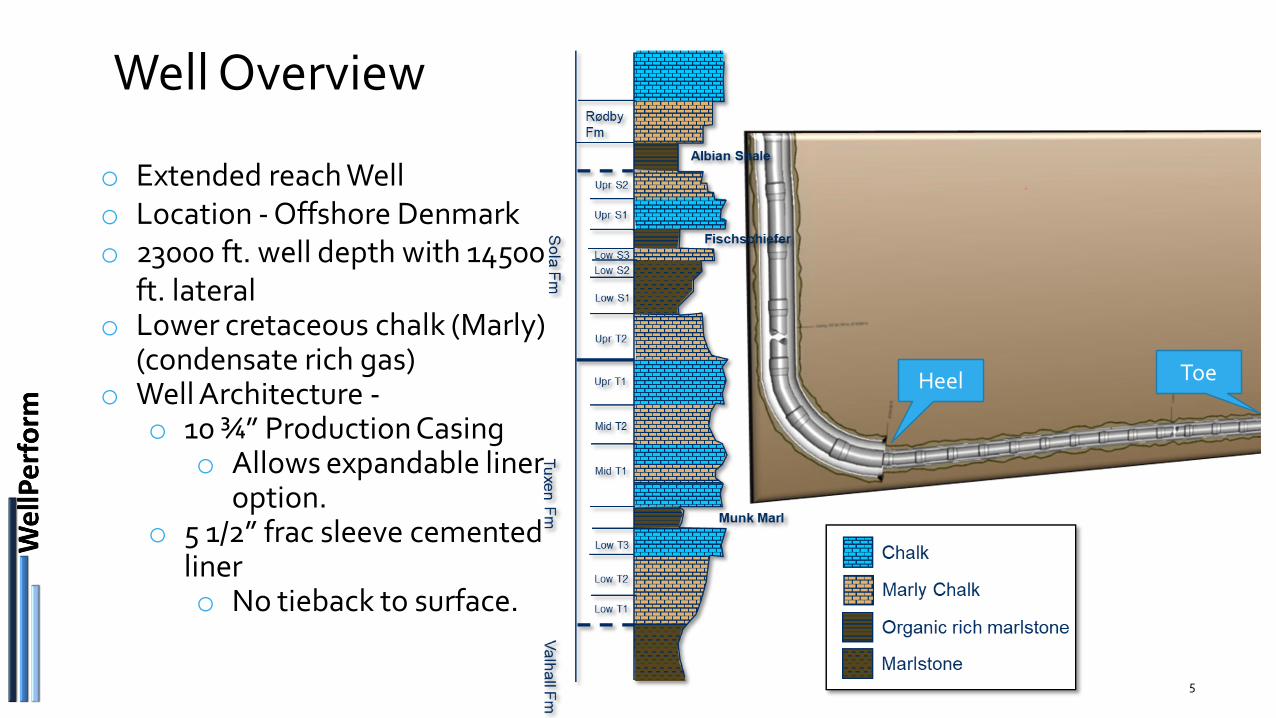
Well Overview
5
o Extended reach Wello Location - Offshore Denmarko 23000 ft. well depth with 14500
ft. lateralo Lower cretaceous chalk (Marly)
(condensate rich gas)o Well Architecture -
o 10 ¾” Production Casingo Allows expandable liner
option.o 5 1/2” frac sleeve cemented
linero No tieback to surface.
Heel Toe
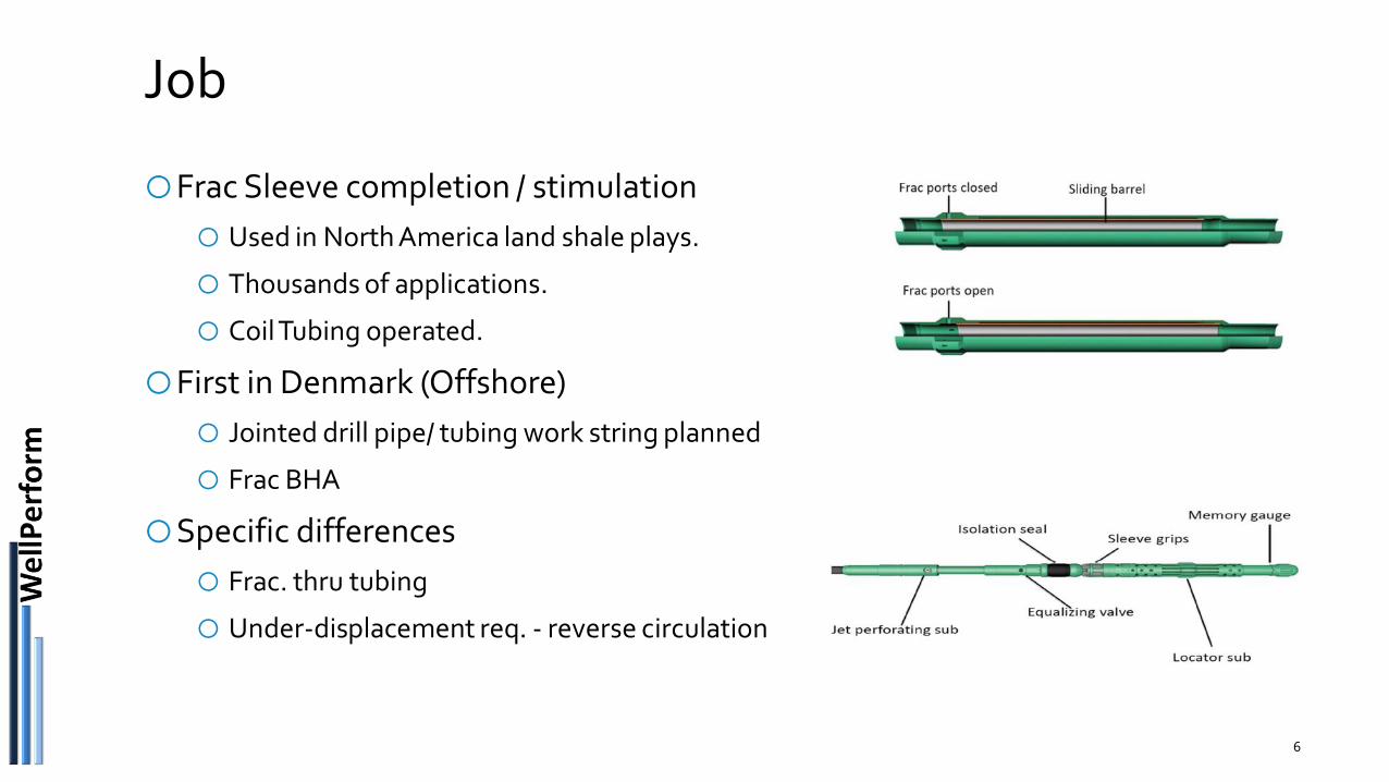
Job
6
oFrac Sleeve completion / stimulation
o Used in North America land shale plays.
o Thousands of applications.
o Coil Tubing operated.
oFirst in Denmark (Offshore)
o Jointed drill pipe/ tubing work string planned
o Frac BHA
oSpecific differences
o Frac. thru tubing
o Under-displacement req. - reverse circulation
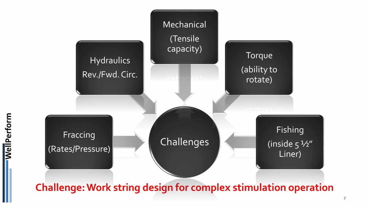
Challenge: Work string design for complex stimulation operation7
ChallengesFraccing
(Rates/Pressure)
Hydraulics
Rev./Fwd. Circ.
Mechanical
(Tensile capacity)
Torque
(ability to rotate)
Fishing
(inside 5 ½” Liner)
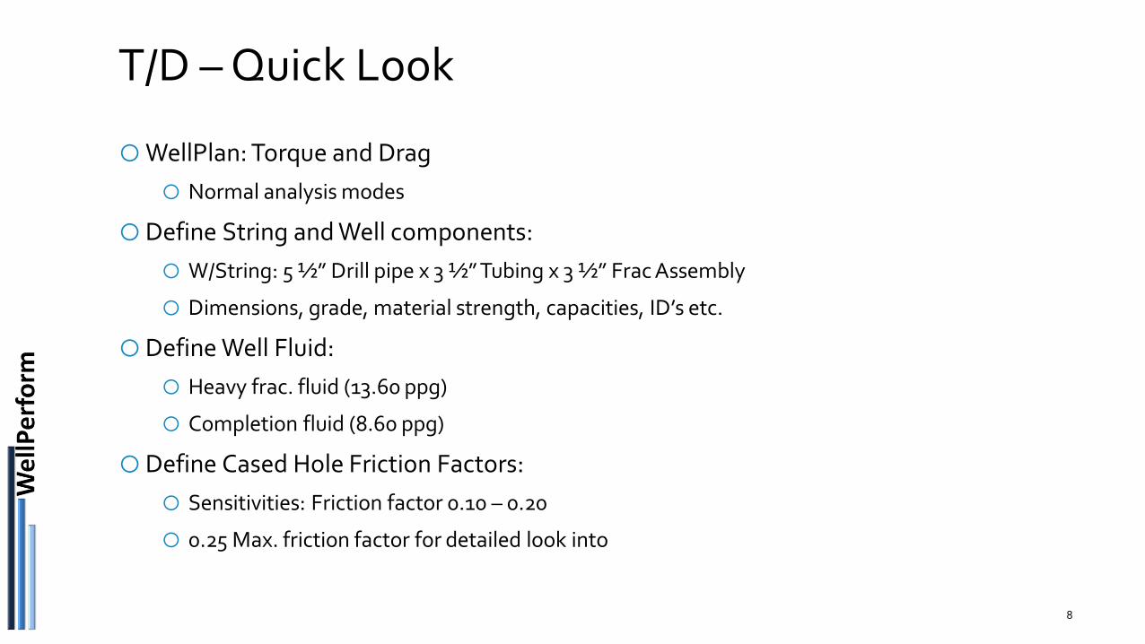
T/D – Quick Look
oWellPlan: Torque and Drag
o Normal analysis modes
oDefine String and Well components:
o W/String: 5 ½” Drill pipe x 3 ½” Tubing x 3 ½” Frac Assembly
o Dimensions, grade, material strength, capacities, ID’s etc.
oDefine Well Fluid:
o Heavy frac. fluid (13.60 ppg)
o Completion fluid (8.60 ppg)
oDefine Cased Hole Friction Factors:
o Sensitivities: Friction factor 0.10 – 0.20
o 0.25 Max. friction factor for detailed look into
8
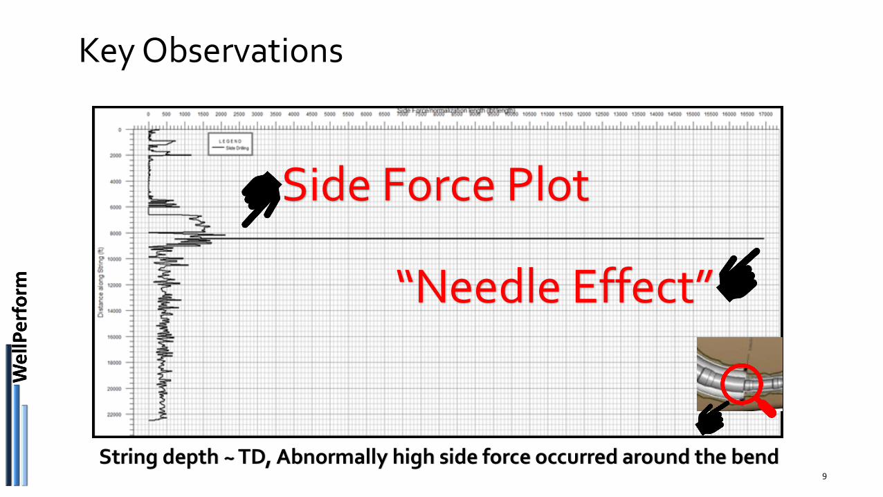
Key Observations
9
Side Force Plot
“Needle Effect”
String depth ~ TD, Abnormally high side force occurred around the bend
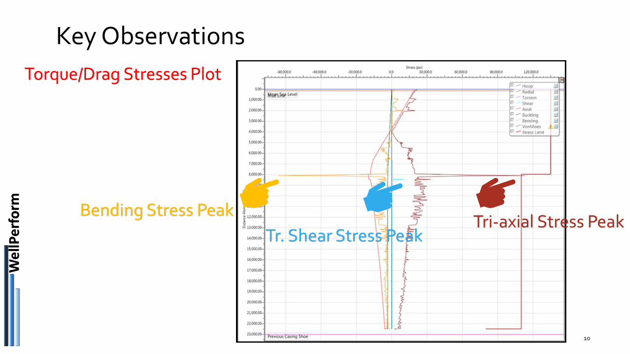
Key Observations
10
Torque/Drag Stresses Plot
Tr. Shear Stress Peak
Bending Stress PeakTri-axial Stress Peak
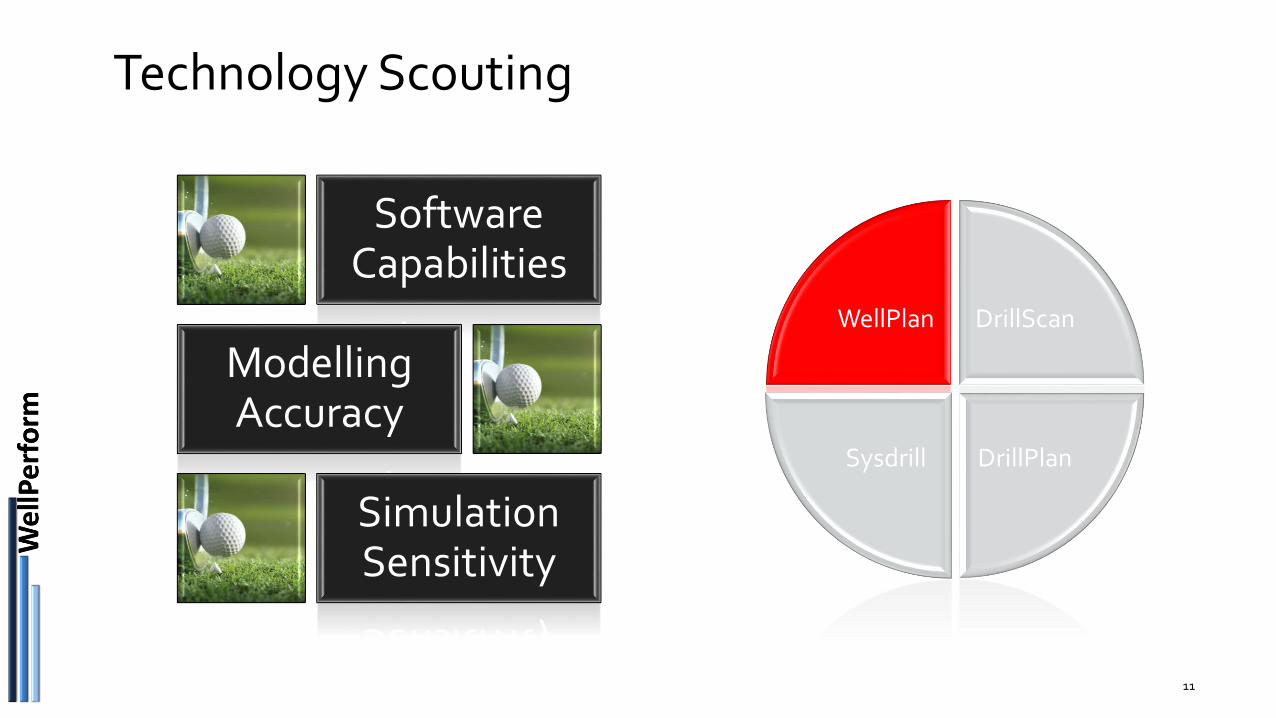
Technology Scouting
11
WellPlan DrillScan
DrillPlanSysdrill
Software Capabilities
Modelling Accuracy
Simulation Sensitivity
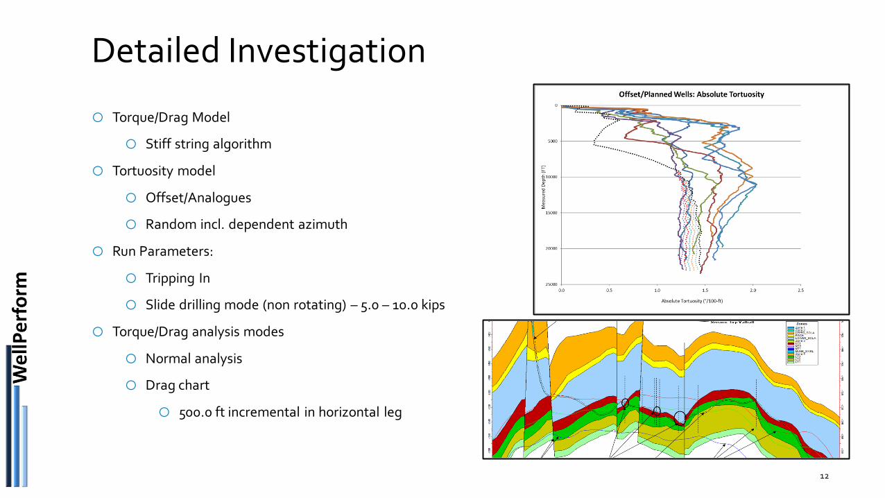
Detailed Investigation
o Torque/Drag Model
o Stiff string algorithm
o Tortuosity model
o Offset/Analogues
o Random incl. dependent azimuth
o Run Parameters:
o Tripping In
o Slide drilling mode (non rotating) – 5.0 – 10.0 kips
o Torque/Drag analysis modes
o Normal analysis
o Drag chart
o 500.0 ft incremental in horizontal leg
12
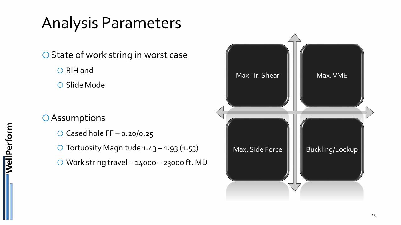
Analysis Parameters
oState of work string in worst case
o RIH and
o Slide Mode
oAssumptions
o Cased hole FF – 0.20/0.25
o Tortuosity Magnitude 1.43 – 1.93 (1.53)
oWork string travel – 14000 – 23000 ft. MD
13
Max. Tr. Shear Max. VME
Max. Side Force Buckling/Lockup
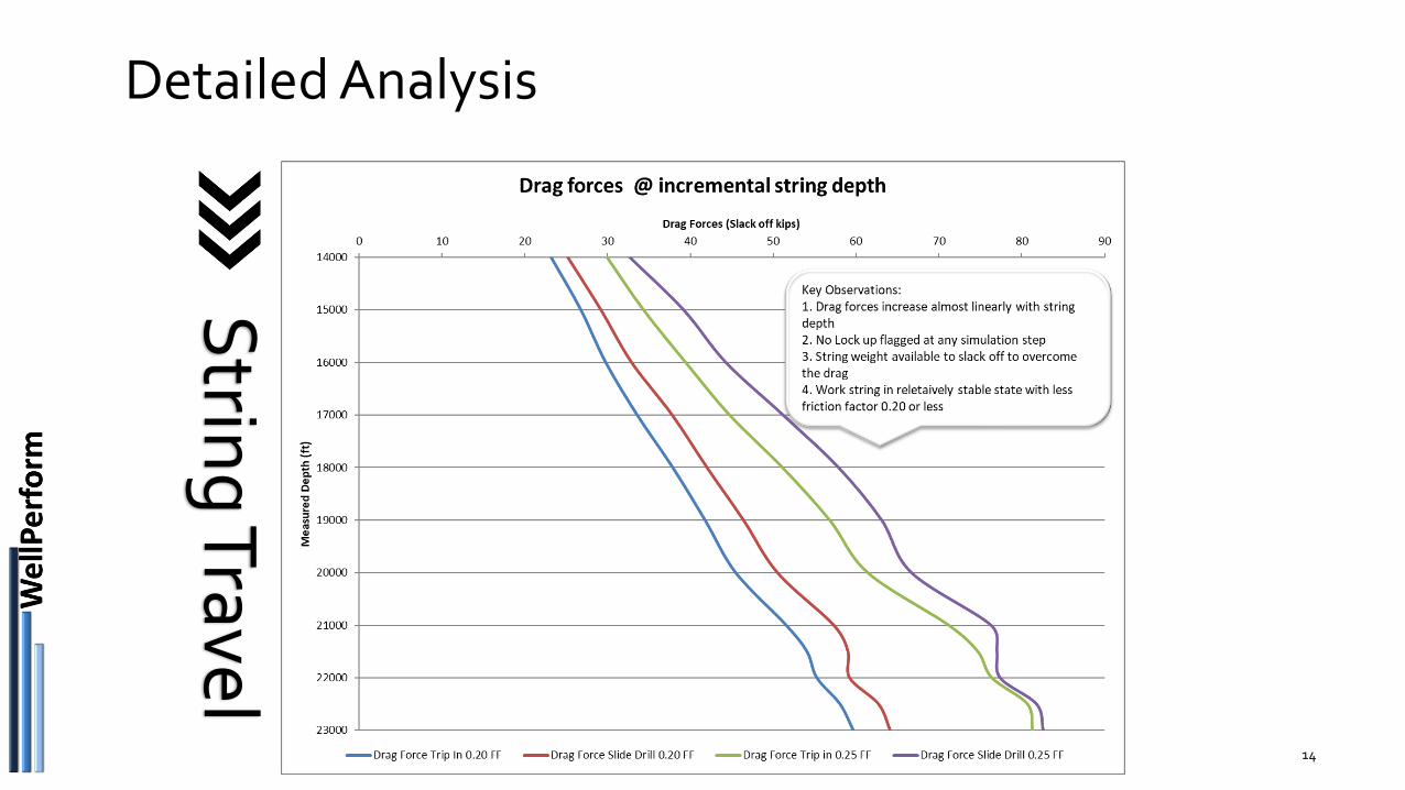
Detailed Analysis
14
Strin
g Travel
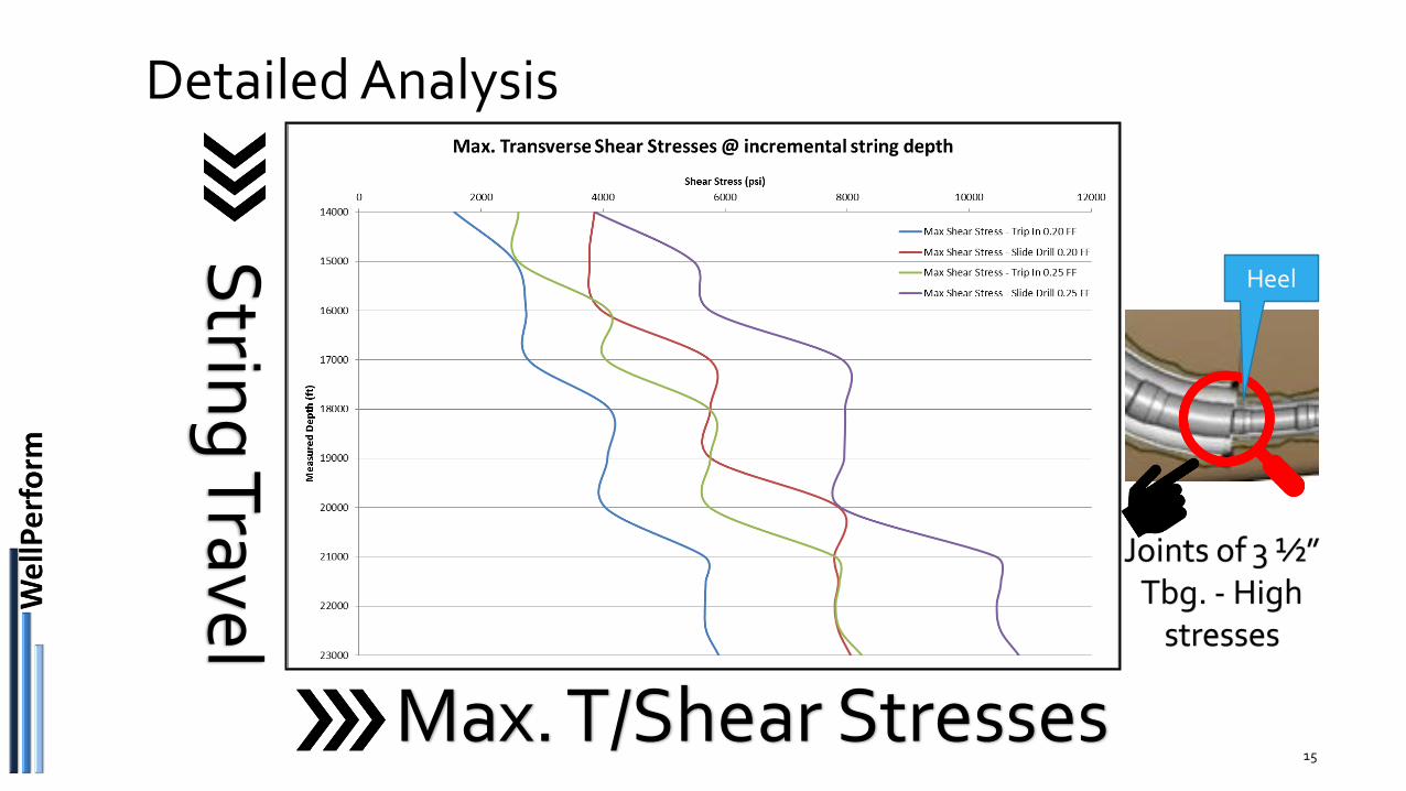
Detailed Analysis
15
Strin
g Travel
Max. T/Shear Stresses
Joints of 3 ½” Tbg. - High
stresses
Heel
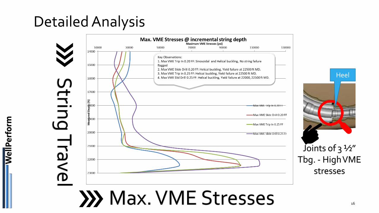
Detailed Analysis
16
Strin
g Travel
Max. VME Stresses
Joints of 3 ½” Tbg. - High VME
stresses
Heel
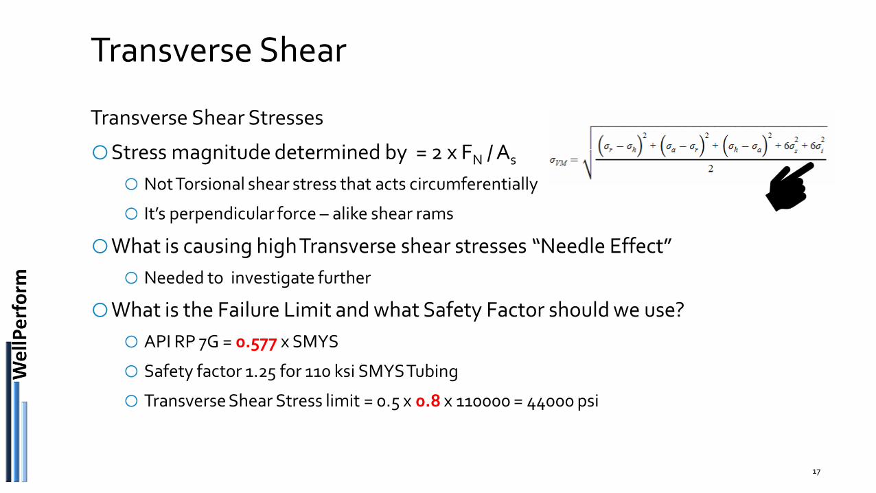
Transverse Shear
Transverse Shear Stresses
oStress magnitude determined by = 2 x FN / As
o Not Torsional shear stress that acts circumferentially
o It’s perpendicular force – alike shear rams
oWhat is causing high Transverse shear stresses “Needle Effect”
o Needed to investigate further
oWhat is the Failure Limit and what Safety Factor should we use?
o API RP 7G = 0.577 x SMYS
o Safety factor 1.25 for 110 ksi SMYS Tubing
o Transverse Shear Stress limit = 0.5 x 0.8 x 110000 = 44000 psi
17
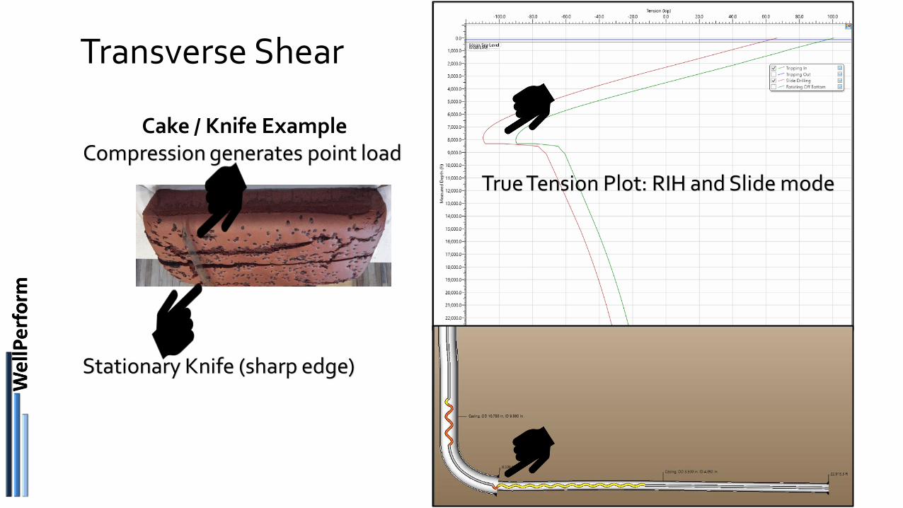
Transverse Shear
18
Stationary Knife (sharp edge)
Cake / Knife ExampleCompression generates point load
True Tension Plot: RIH and Slide mode
Solution / Fix
19
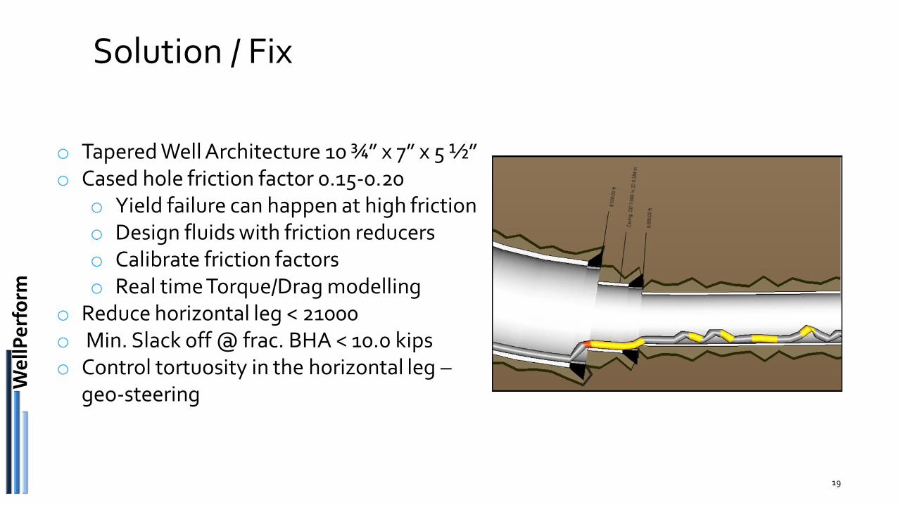
o Tapered Well Architecture 10 ¾” x 7” x 5 ½”o Cased hole friction factor 0.15-0.20
o Yield failure can happen at high frictiono Design fluids with friction reducerso Calibrate friction factorso Real time Torque/Drag modelling
o Reduce horizontal leg < 21000o Min. Slack off @ frac. BHA < 10.0 kipso Control tortuosity in the horizontal leg –
geo-steering
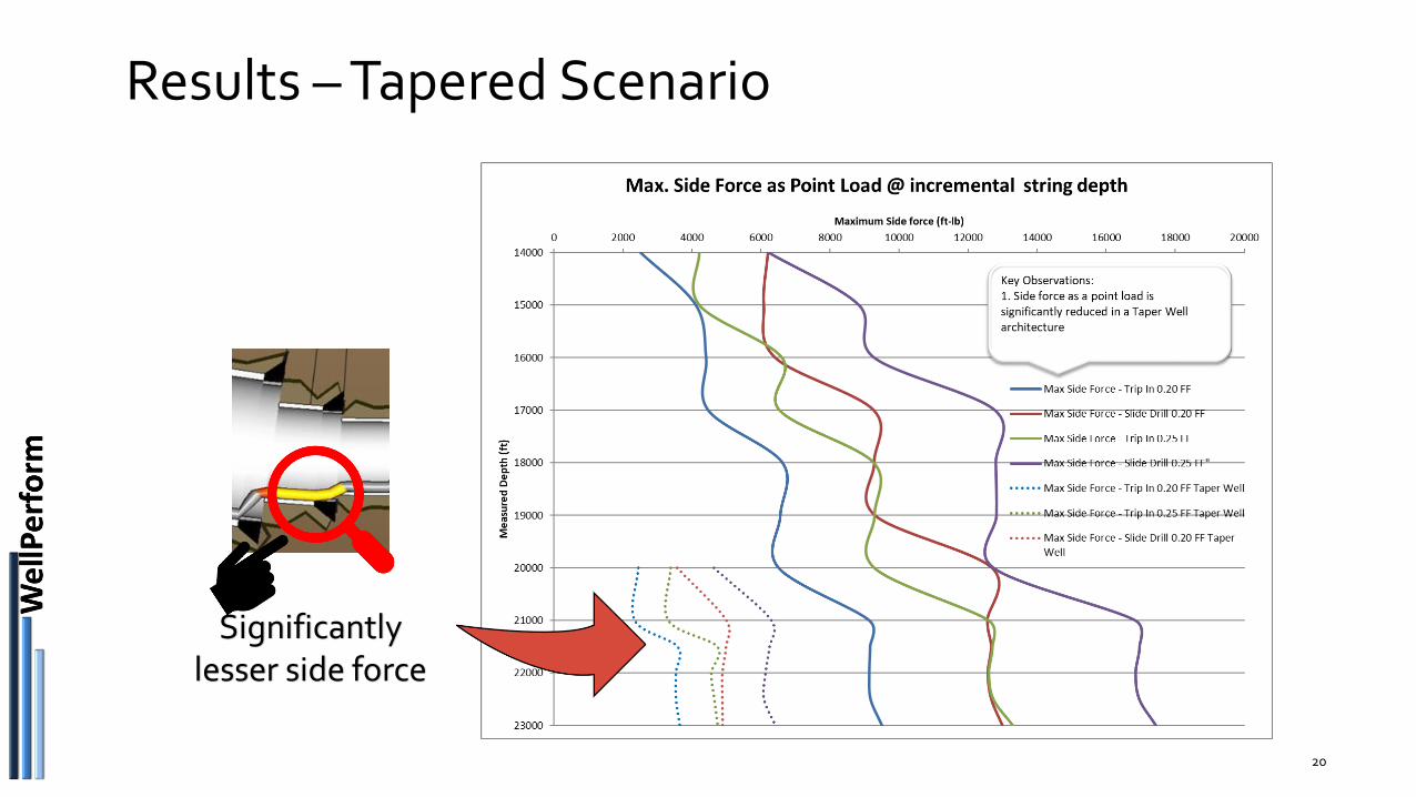
Results – Tapered Scenario
20
Significantly lesser side force

Results – Tapered Scenario
21
Significantly reduced
transverse shear stresses
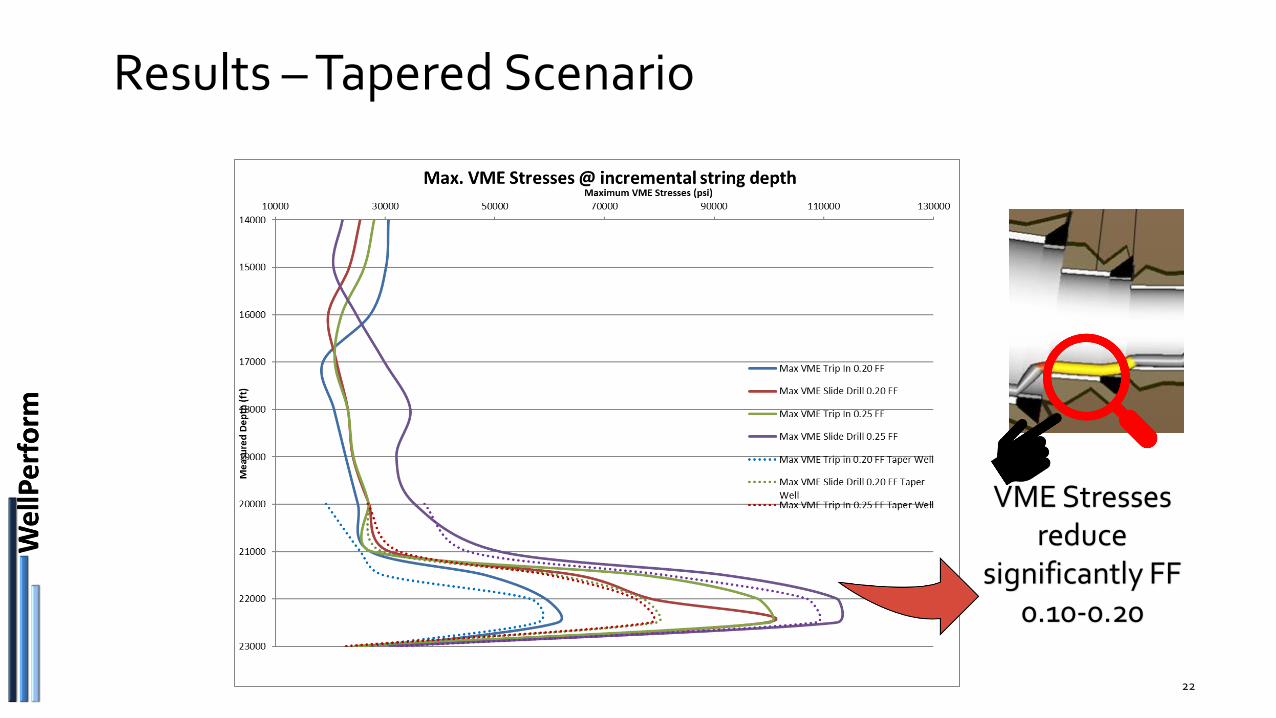
Results – Tapered Scenario
22
VME Stresses reduce
significantly FF 0.10-0.20
Summary
23
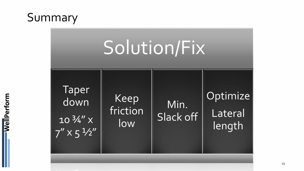
Solution/Fix
Taper down
10 ¾” x 7” x 5 ½”
Keep friction
low
Min. Slack off
Optimize
Lateral length
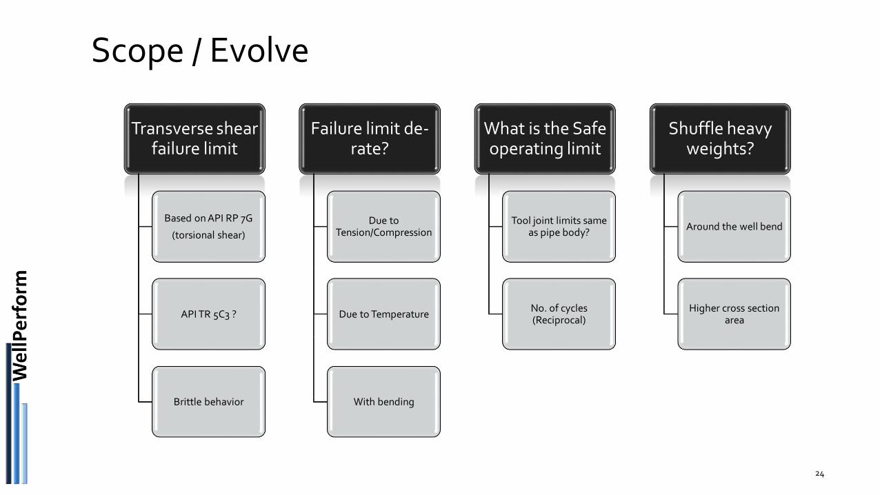
Scope / Evolve
Transverse shear failure limit
Based on API RP 7G
(torsional shear)
API TR 5C3 ?
Brittle behavior
Failure limit de-rate?
Due to Tension/Compression
Due to Temperature
With bending
What is the Safe operating limit
Tool joint limits same as pipe body?
No. of cycles (Reciprocal)
Shuffle heavy weights?
Around the well bend
Higher cross section area
24

Thank You
EXTERNAL © 2019 Halliburton. All rights reserved.
Your feedback is very important to us.Please open the LIFE2019 app to answer a few short questions on this presentation.