Embed Size (px)
Citation preview
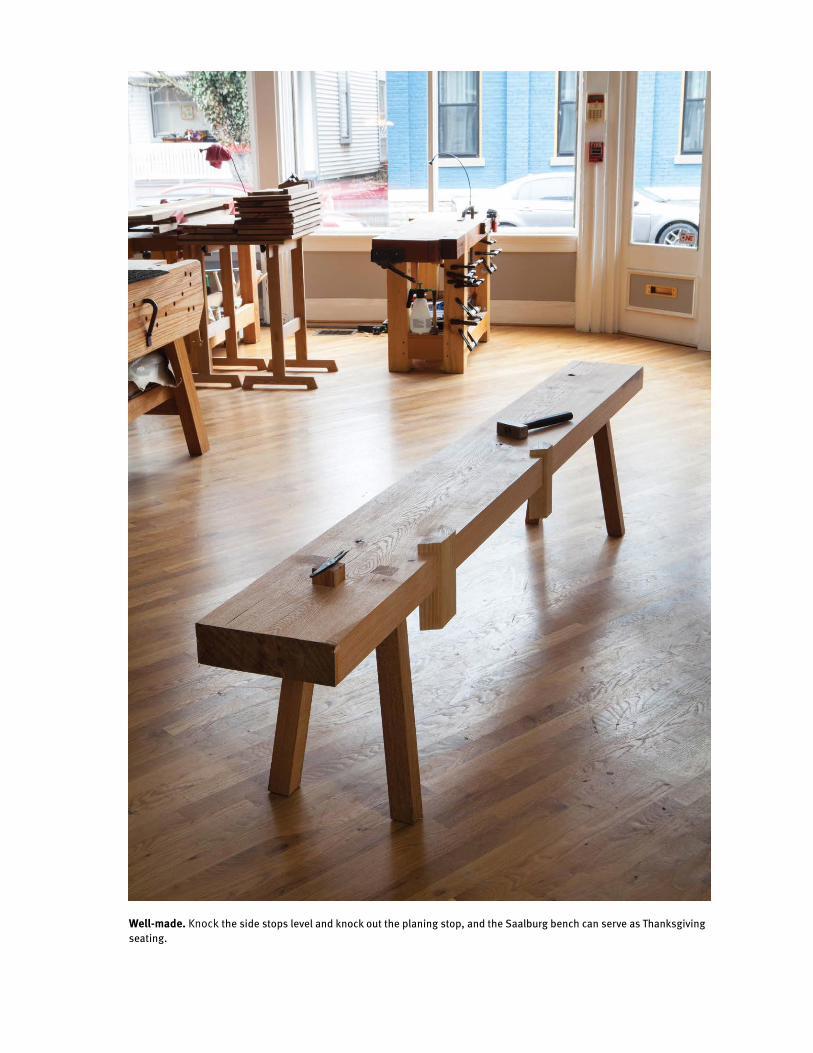
Well-made. Knock the side stops level and knock out the planing stop, and the Saalburg bench can serve as Thanksgiving seating.
111
VIISaalburg Workbench
German archaeologists are a good deal more practical than the French, British or Ameri-
can ones I’ve worked with. But that knowledge didn’t prepare me for the three little words Rüdiger Schwarz said to me on June 8, 2017.
“Pick it up.”The “it” was a low workbench that
had been recovered in 1901 from well No. 49 at the Roman fort in Saalburg, Germany. Though the scientists at Saalburg haven’t been able to date this particular workbench, a second similar bench from well No. 49 was dated to 187 C.E.
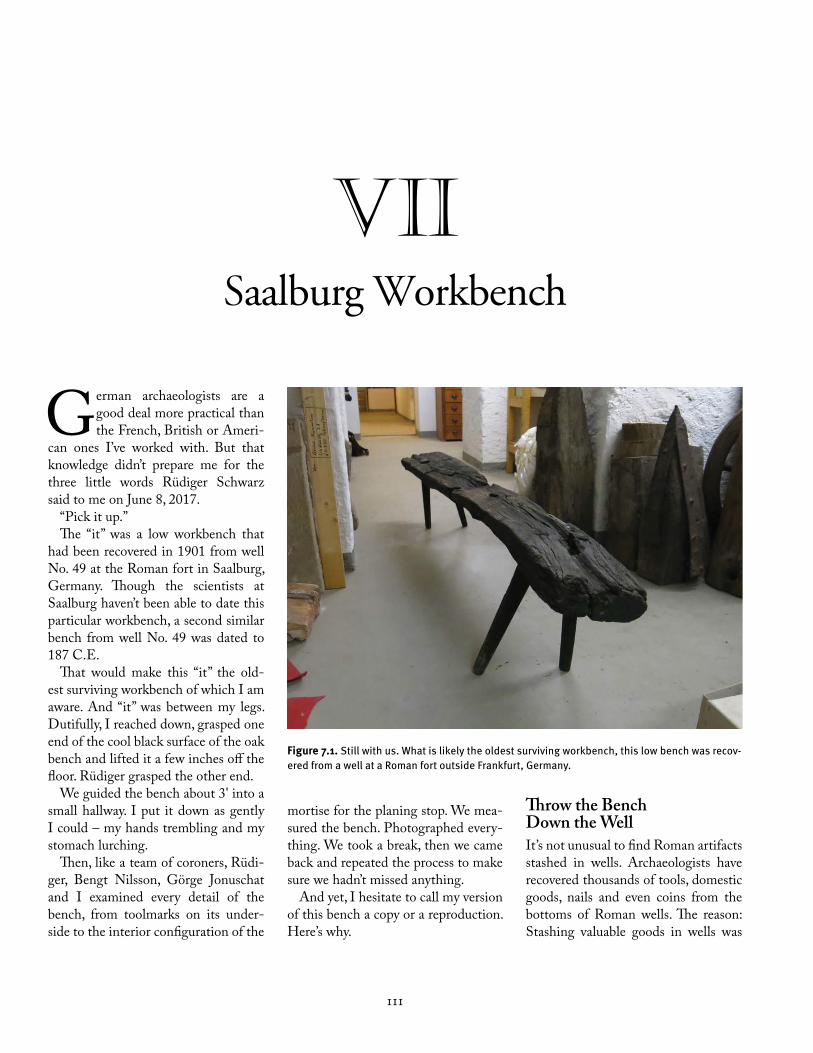
That would make this “it” the old-est surviving workbench of which I am aware. And “it” was between my legs. Dutifully, I reached down, grasped one end of the cool black surface of the oak bench and lifted it a few inches off the floor. Rüdiger grasped the other end.
We guided the bench about 3' into a small hallway. I put it down as gently I could – my hands trembling and my stomach lurching.
Then, like a team of coroners, Rüdi-ger, Bengt Nilsson, Görge Jonuschat and I examined every detail of the bench, from toolmarks on its under-side to the interior configuration of the
mortise for the planing stop. We mea-sured the bench. Photographed every-thing. We took a break, then we came back and repeated the process to make sure we hadn’t missed anything.
And yet, I hesitate to call my version of this bench a copy or a reproduction. Here’s why.
Throw the Bench Down the WellIt’s not unusual to find Roman artifacts stashed in wells. Archaeologists have recovered thousands of tools, domestic goods, nails and even coins from the bottoms of Roman wells. The reason: Stashing valuable goods in wells was
Figure 7.1. Still with us. What is likely the oldest surviving workbench, this low bench was recov-ered from a well at a Roman fort outside Frankfurt, Germany.
112 CHAPTER VII
a typical Roman reaction to the threat of an overwhelming attack. If the Ro-mans threw their precious bits down wells before retreating, there’s a chance they could recover their valuables later. And if they weren’t able to recover their items, there’s a chance their attackers wouldn’t find them, either.
But before we start discussing the fall of Saalburg, let’s look at how it started.
The Saalburg fort was founded about 85 C.E. as two earthen enclosures to protect a mountain pass. This was later improved to a wood and earth fort. In the second century C.E., Saalburg was expanded to become an impressive stone fort that housed a “cohort,” a unit of about 500-600 Romans. The fort served as one of the important links in the “limes” (pronounced “lee-mez” and not like the citrus), which was the frontier between the Roman Empire and the hostile Germanic tribes to the north.
About 260 C.E., the Roman limes fell. All areas east of the Rhine River were lost to the Germanic tribes of the north. Saalburg was abandoned during this time, apparently without a fight. Yet the fact that the fort’s wells were filled with tools and other important commercial objects suggests that its occupants felt threatened.
After the fort was abandoned, it was used as a quarry. And its history and very existence faded away until the late 19th century. After decades of research into the Saalburg fort by archaeologists, Kaiser Wilhelm II ordered in 1897 for the fort to be reconstructed. It is now an open-air museum and research cen-ter for archaeologists who study the limes and Roman technology.
We Go BelowToday, below the museum is a climate-controlled room with thousands of Roman objects. That’s where museum educator Rüdiger Schwarz took us one summer day in June. Its entrance is be-
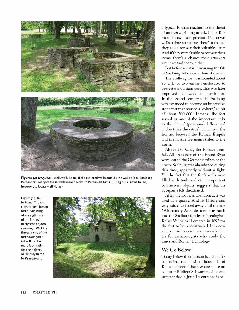
Figures 7.2 &7.3. Well, well, well. Some of the restored wells outside the walls of the Saalburg Roman fort. Many of these wells were filled with Roman artifacts. During our visit we failed, however, to locate well No. 49.
Figure 7.4. Return to Rome. The re-constructed Roman fort at Saalburg offers a glimpse of the fort as it likely stood 1,800 years ago. Walking through one of the fort’s four gates is thrilling. Even more fascinating are the objects on display in the fort’s museum.

Saalburg Workbench 113
low grade, like a cellar door. Then you traipse down a few steps to a masonry-lined room that looks like the mechan-ical area of a school or office building. There’s equipment to control humid-ity. Lots of locked doors. Any janitor would feel at home.
Rüdiger unlocks a couple of doors and the scenery changes. It’s still a climate-controlled basement, but the hallways are lined with wooden shelves that go from floor to ceiling. And they are filled with bricks, pottery and woodwork. All of it neatly labeled. Though we’re walking at a normal pace, I stumble when my eye latches onto a label or an interesting ceramic. My feet don’t know what to do – move or stop.
We make a left turn; as do the shelves. To my left are banks of wide and shal-low drawers filled with hundreds of ar-tifacts. The only sound is a buzz from the lights above as they flicker on and warm up. I don’t suffer vertigo, but the floor seems to sweep upward as we pass into a cluster of wooden objects – wheels, stools and pieces of bridges that are bound in iron. Every wooden object is blackened from its time in a well that had no oxygen but lots and lots of iron objects.
And then there it is – the workbench standing on four legs like a lame dog. None of its legs are in the same plane, likely the result of it being waterlogged for hundreds of years and then being dried out in 1901.1 At some point, the benchtop split in its middle across its width, but it has been mended and looks sturdy and ready for straddling. There’s a piece removed from the back end where archaeologists attempted to date the bench – the offcut is also handy so you can see the annular rings of the tree and the way the iron has leached its way deep into the fibers of the workbench. It is black through and through.
I want to sit down, but the only seats available are 1,800-year-old stools and
benches. And that’s when I realized the bench was between my legs.
“Pick it up.”For me, the Saalburg workbench is a
touchstone and a mystery. As the ear-liest surviving workbench, it is a link to woodworkers who existed centuries before us. Their tools are remarkably similar to ours. Yet their workbenches are a bit foreign. Many of the benches are knee-high and have workholding schemes that are dirt simple and some-what alien.
When I’ve shown images of these early benches to other woodworkers, many have ready explanations for what this peg did or that notch was used for. But they don’t really know. The only way to find out – aside from cloning an old Roman woodworker – is to build these benches and build furniture us-ing them. And even then, it’s difficult to be certain you are on the right path.
The following is an account of how I built the Saalburg bench. It’s incredibly simple – just eight pieces of wood. In fact, thinking about building the bench
took much longer than actually con-structing it. We’ll be discussing both the thinking and the building so that future generations can easily take issue with my assumptions and decisions. Yup, I’m pulling down my pants, aca-demically speaking.
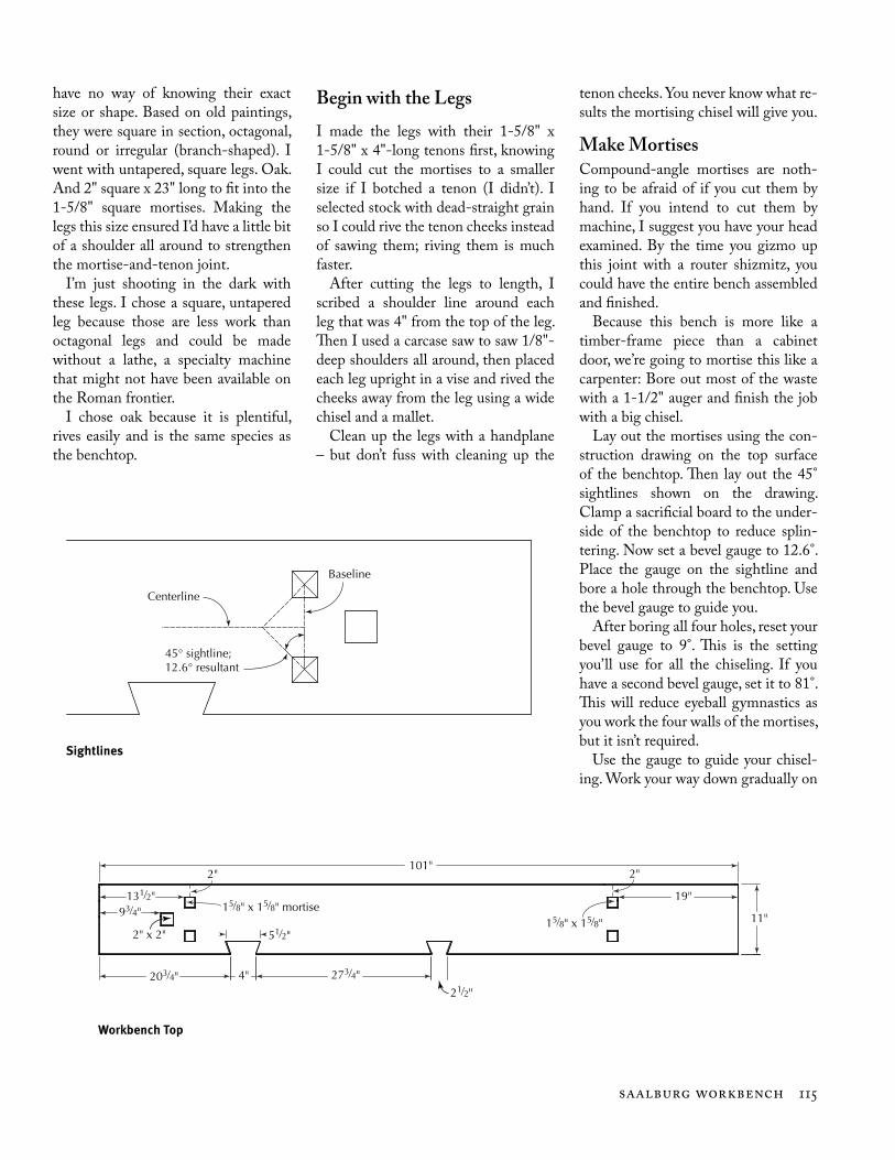
Design DetailsThere’s little doubt that the benchtop that was pulled out of well No. 49 was a low bench, despite the fact that its legs were missing. The top is too nar-row (10" on one end; 11" on the other) for a tall bench, and its mortises are an-gled in such a manner that a low bench makes sense.
But it’s impossible to know at ex-actly what angle the legs were origi-nally oriented because modern legs were wedged into the original mortises when the workbench was put on dis-play at Saalburg many years ago. The legs are still wedged in there, and I don’t think they’re coming out anytime soon.
So, deciding on the rake and splay for the legs required a little practical imag-ination. From a woodworking perspec-tive, it makes sense for the rake and splay to be equal – that would make chopping the mortises straightforward and simple because there is only one angle to follow during the process.
1 The primary problem in interpreting the bench is what 1,800 years in a well will do to a slab of wood. Rüdiger Schwarz at Saalburg explained the problem perfectly that summer when he showed us a wood-en yoke that had been pulled from one of the wells. The wooden yoke was shriveled and distorted, like someone had made a Shrinky Dink of a yoke and left it in the oven too long. Next to the yoke was a casting that had been made of the yoke right after it has been rescued from the well. It looked like a new farm implement. Schwarz explained that wooden objects, such as the workbench and the yoke, had distorted noticeably after they dried. So the work-bench was likely much less twisted than it is today.
2 For woodworkers who use “resultant” and “sight-line” angles, the legs have a 12.6° resultant angle with a 45° sightline.
Figure 7.5. Another bench? Two halves of a similar low bench were found in the same well. This bench, however, did not have a vis-ible hole for a planing stop.
114 CHAPTER VII
After some experimentation on a small model of the bench, I decided to use 9° rake and 9° splay.2 These some-what shallow angles kicked the legs out to a sweet spot: With the benchtop at kneecap height, the legs would add sta-bility to the bench but not be a tripping hazard by jutting out wildly from the shadow of its top.
Also, the shallow rake and splay an-gles ensured that the legs’ tenons would be surrounded by plenty of wood on the underside of the benchtop. More radical angles would thin the mortise wall near the edge of the benchtop, weakening the joint.
The second design detail involved the workbench top itself. The original benchtop tapers both in its thickness and its width. The original is 10" wide at the front end and 11" wide at the rear. The thickness is 2-1/2" on the long edge with the dovetail-shaped slots. On the other edge, the slab measures 3" thick in most places and 3-1/2" in a couple places.
After talking about the bench with chairmaker and green woodworker Peter Galbert (and showing him all my photos of the slab), he suspected the top might have been rived from an oak log, not sawn. Aside from the large knot in the benchtop, the grain runs quite straight, which supports Pe-ter’s suggestion. Plus, riving a piece of this size would take minutes. Sawing it would take hours. So, if I had built this bench in 187 C.E., I’d have used wedges and a sledge – not a saw.
Today, however, I don’t have access to oak trunks of this diameter and qual-ity, so I ended up using a sawn slab of red oak that came from North Caro-lina. It’s 3-7/16" thick. I thought about thinning the slab’s thickness on one edge to match the dimensions from Saalburg, but I couldn’t see any advan-tage (other than burning calories). So, my top is of a consistent thickness.
For the legs, I was in the dark. We
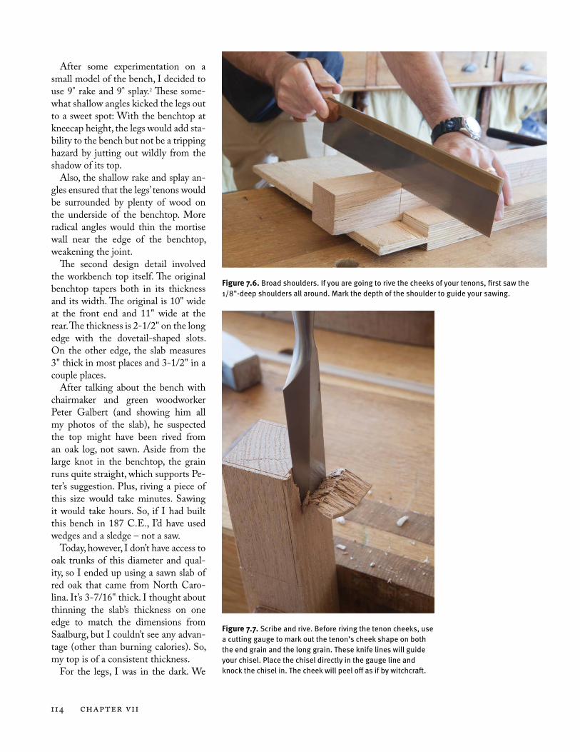
Figure 7.6. Broad shoulders. If you are going to rive the cheeks of your tenons, first saw the 1/8"-deep shoulders all around. Mark the depth of the shoulder to guide your sawing.
Figure 7.7. Scribe and rive. Before riving the tenon cheeks, use a cutting gauge to mark out the tenon’s cheek shape on both the end grain and the long grain. These knife lines will guide your chisel. Place the chisel directly in the gauge line and knock the chisel in. The cheek will peel off as if by witchcraft.
Saalburg Workbench 115
have no way of knowing their exact size or shape. Based on old paintings, they were square in section, octagonal, round or irregular (branch-shaped). I went with untapered, square legs. Oak. And 2" square x 23" long to fit into the 1-5/8" square mortises. Making the legs this size ensured I’d have a little bit of a shoulder all around to strengthen the mortise-and-tenon joint.
I’m just shooting in the dark with these legs. I chose a square, untapered leg because those are less work than octagonal legs and could be made without a lathe, a specialty machine that might not have been available on the Roman frontier.
I chose oak because it is plentiful, rives easily and is the same species as the benchtop.
Begin with the LegsI made the legs with their 1-5/8" x 1-5/8" x 4"-long tenons first, knowing I could cut the mortises to a smaller size if I botched a tenon (I didn’t). I selected stock with dead-straight grain so I could rive the tenon cheeks instead of sawing them; riving them is much faster.
After cutting the legs to length, I scribed a shoulder line around each leg that was 4" from the top of the leg. Then I used a carcase saw to saw 1/8"-deep shoulders all around, then placed each leg upright in a vise and rived the cheeks away from the leg using a wide chisel and a mallet.
Clean up the legs with a handplane – but don’t fuss with cleaning up the
93⁄4"
2" x 2"
131⁄2"15⁄8" x 15⁄8" mortise
203⁄4"
51⁄2"
4" 273⁄4"
21⁄2"
19"
2"101"
11"15⁄8" x 15⁄8"
2"
Workbench Top
45° sightline;12.6° resultant
Baseline
Centerline
Sightlines
tenon cheeks. You never know what re-sults the mortising chisel will give you.
Make MortisesCompound-angle mortises are noth-ing to be afraid of if you cut them by hand. If you intend to cut them by machine, I suggest you have your head examined. By the time you gizmo up this joint with a router shizmitz, you could have the entire bench assembled and finished.
Because this bench is more like a timber-frame piece than a cabinet door, we’re going to mortise this like a carpenter: Bore out most of the waste with a 1-1/2" auger and finish the job with a big chisel.
Lay out the mortises using the con-struction drawing on the top surface of the benchtop. Then lay out the 45° sightlines shown on the drawing. Clamp a sacrificial board to the under-side of the benchtop to reduce splin-tering. Now set a bevel gauge to 12.6°. Place the gauge on the sightline and bore a hole through the benchtop. Use the bevel gauge to guide you.
After boring all four holes, reset your bevel gauge to 9°. This is the setting you’ll use for all the chiseling. If you have a second bevel gauge, set it to 81°. This will reduce eyeball gymnastics as you work the four walls of the mortises, but it isn’t required.
Use the gauge to guide your chisel-ing. Work your way down gradually on

116 CHAPTER VII
all four walls of the mortise, moving the gauge as you switch to a new wall.
After you are about four-fifths of the way through the mortise, flip the benchtop over and begin beavering on the underside. You’ll be able to lay out the mortise on the underside using the existing mortise and the waste left around the mortise’s hole. You don’t need this part of the mortise to be per-fect. If it ends up a little wider than expected at the bottom, the leg will fit fine. Glue and some good wedges will fix minor inaccuracies.
After you finish a mortise, fit a leg to that mortise and drive it home. Mark that leg and mortise to marry them. Then cut the next mortise.
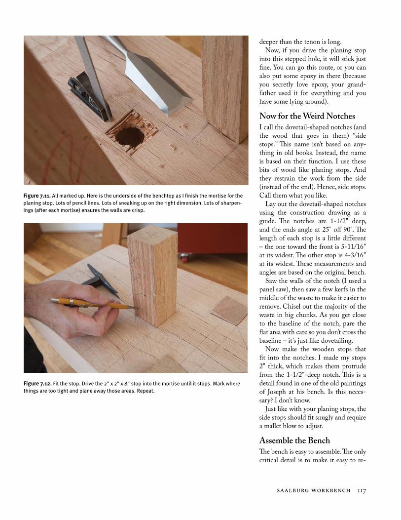
One More MortiseBefore you put your beefy chisel away, cut the 2" x 2" mortise for the planing stop. Compared to the compound-an-
gle mortises, this hole is kid’s stuff. It’s so easy that it could have been a nice little warm-up before tacking the leg mortises. Um. Oops. Oh well.
Bore out the majority of the waste with the same auger you used for the leg mortises. Clean up the walls with the same wide chisel. The only differ-ence is that you can use a try square (instead of a bevel gauge) to guide your chiseling. And you can easily mark out the exit wound on the underside of the benchtop.
With the planing stop’s mortise complete, fit the wooden stop to the hole. This is a matter of driving it in and planing away the high spots un-til you get a tight fit. The stop should be adjustable with one-handed mallet blows, moving about 1/8" up or down with each blow.
If it moves .001" with each strike or falls lifelessly out of its hole, try again.
If you have a metal planing stop, this is the time to marry it to the wooden one. Usually metal planing stops have a tapered metal tenon that is square in section. For the mortise, I drill a stepped hole. The first hole is the same size as the dimension of the metal tenon at its top, right under the teeth. For my stop, this was 3/4". So, I drilled a 3/4" hole into the stop. The hole’s depth was equal to about half the length of the tenon.3
Now measure the tenon’s thickness at its smaller tip (mine was 5/8" thick). Drill a 5/8" hole that is a little bit
Figure 7.8. Not a masochist. I don’t own a 1-1/2" hand-powered auger, so I gladly grabbed my electric drill for this operation. Note the right-angle grip on my drill. If you have one, use it. Your unbroken wrists will thank you.
Figure 7.9. Accurate eyes. If you take your time, you’ll be surprised by how accurate your compound-angle mortises can be. Just make sure you eyeball the blade of your bevel gauge with the back face of your chisel before every strike. This might seem a slow way to work, but it’s faster than fixing overcuts or undercuts.
Figure 7.10. On your feet. Drive in all four legs, turn the bench over and check your work. If your bench doesn’t immediately capsize, you’re in good shape.
3 “But wait,” I know you are asking. “If the hole is the same size as the tenon’s width, how will things stick together? The answer is to measure the metal tenon from corner-to-corner. That dimension is larger than when measuring the tenon from cheek-to-cheek.
Saalburg Workbench 117
deeper than the tenon is long.Now, if you drive the planing stop
into this stepped hole, it will stick just fine. You can go this route, or you can also put some epoxy in there (because you secretly love epoxy, your grand-father used it for everything and you have some lying around).
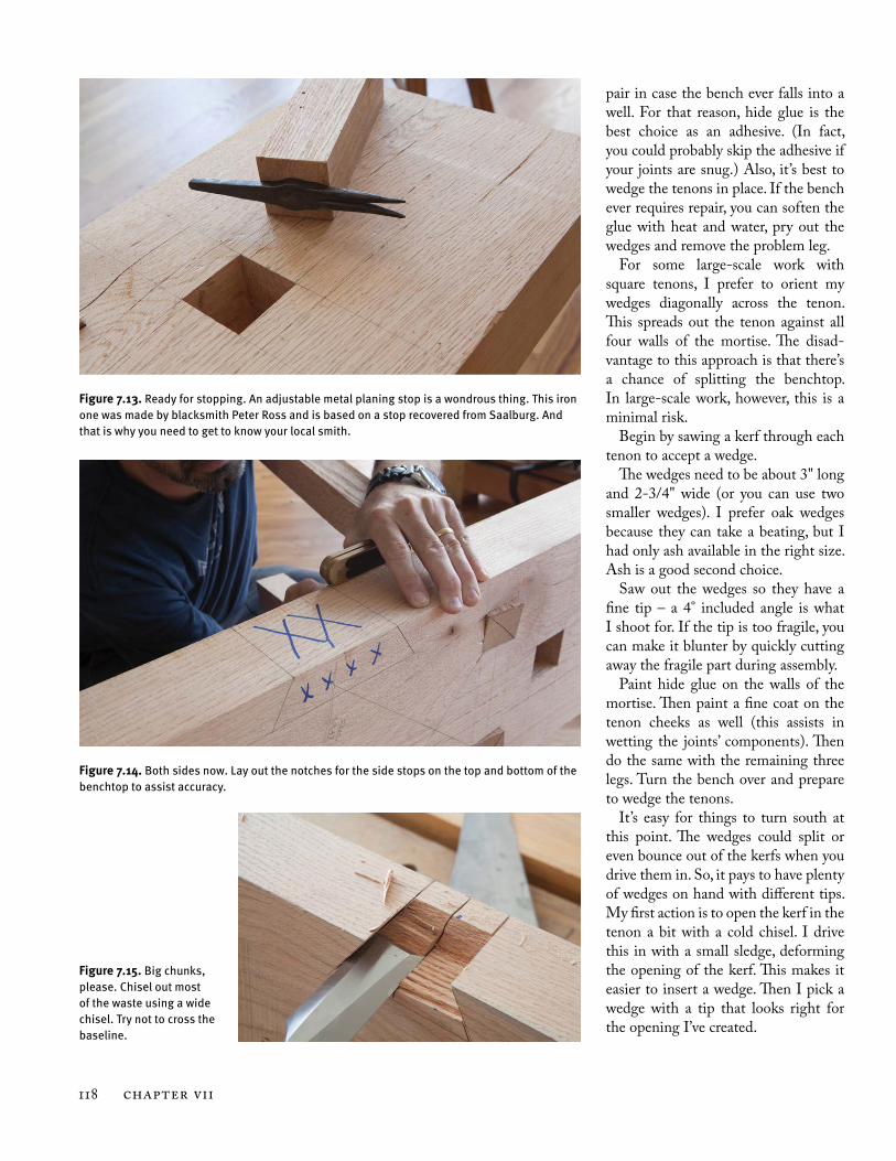
Now for the Weird NotchesI call the dovetail-shaped notches (and the wood that goes in them) “side stops.” This name isn’t based on any-thing in old books. Instead, the name is based on their function. I use these bits of wood like planing stops. And they restrain the work from the side (instead of the end). Hence, side stops. Call them what you like.
Lay out the dovetail-shaped notches using the construction drawing as a guide. The notches are 1-1/2" deep, and the ends angle at 25° off 90°. The length of each stop is a little different – the one toward the front is 5-11/16" at its widest. The other stop is 4-3/16" at its widest. These measurements and angles are based on the original bench.
Saw the walls of the notch (I used a panel saw), then saw a few kerfs in the middle of the waste to make it easier to remove. Chisel out the majority of the waste in big chunks. As you get close to the baseline of the notch, pare the flat area with care so you don’t cross the baseline – it’s just like dovetailing.
Now make the wooden stops that fit into the notches. I made my stops 2" thick, which makes them protrude from the 1-1/2"-deep notch. This is a detail found in one of the old paintings of Joseph at his bench. Is this neces-sary? I don’t know.
Just like with your planing stops, the side stops should fit snugly and require a mallet blow to adjust.
Assemble the BenchThe bench is easy to assemble. The only critical detail is to make it easy to re-
Figure 7.11. All marked up. Here is the underside of the benchtop as I finish the mortise for the planing stop. Lots of pencil lines. Lots of sneaking up on the right dimension. Lots of sharpen-ings (after each mortise) ensures the walls are crisp.
Figure 7.12. Fit the stop. Drive the 2" x 2" x 8" stop into the mortise until it stops. Mark where things are too tight and plane away those areas. Repeat.
118 CHAPTER VII
pair in case the bench ever falls into a well. For that reason, hide glue is the best choice as an adhesive. (In fact, you could probably skip the adhesive if your joints are snug.) Also, it’s best to wedge the tenons in place. If the bench ever requires repair, you can soften the glue with heat and water, pry out the wedges and remove the problem leg.
For some large-scale work with square tenons, I prefer to orient my wedges diagonally across the tenon. This spreads out the tenon against all four walls of the mortise. The disad-vantage to this approach is that there’s a chance of splitting the benchtop. In large-scale work, however, this is a minimal risk.
Begin by sawing a kerf through each tenon to accept a wedge.
The wedges need to be about 3" long and 2-3/4" wide (or you can use two smaller wedges). I prefer oak wedges because they can take a beating, but I had only ash available in the right size. Ash is a good second choice.
Saw out the wedges so they have a fine tip – a 4° included angle is what I shoot for. If the tip is too fragile, you can make it blunter by quickly cutting away the fragile part during assembly.
Paint hide glue on the walls of the mortise. Then paint a fine coat on the tenon cheeks as well (this assists in wetting the joints’ components). Then do the same with the remaining three legs. Turn the bench over and prepare to wedge the tenons.
It’s easy for things to turn south at this point. The wedges could split or even bounce out of the kerfs when you drive them in. So, it pays to have plenty of wedges on hand with different tips. My first action is to open the kerf in the tenon a bit with a cold chisel. I drive this in with a small sledge, deforming the opening of the kerf. This makes it easier to insert a wedge. Then I pick a wedge with a tip that looks right for the opening I’ve created.
Figure 7.13. Ready for stopping. An adjustable metal planing stop is a wondrous thing. This iron one was made by blacksmith Peter Ross and is based on a stop recovered from Saalburg. And that is why you need to get to know your local smith.
Figure 7.14. Both sides now. Lay out the notches for the side stops on the top and bottom of the benchtop to assist accuracy.
Figure 7.15. Big chunks, please. Chisel out most of the waste using a wide chisel. Try not to cross the baseline.
Saalburg Workbench 119
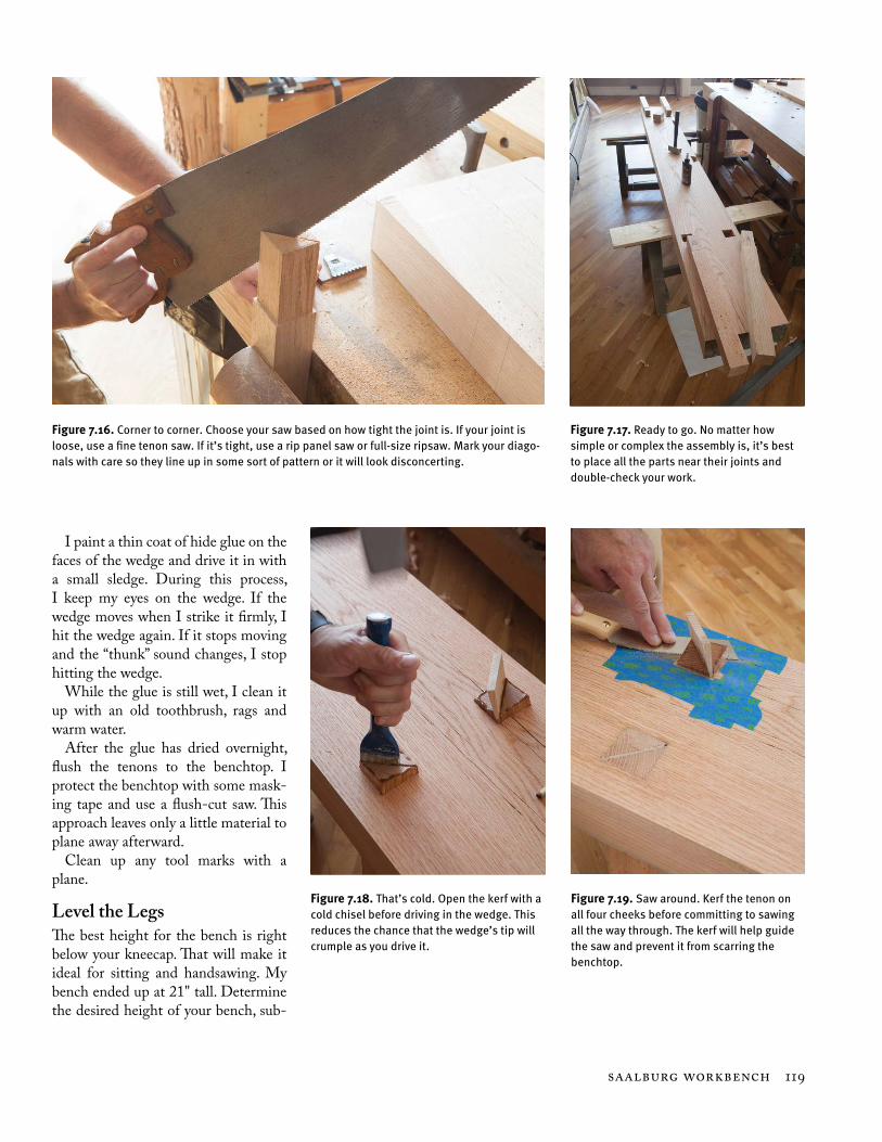
I paint a thin coat of hide glue on the faces of the wedge and drive it in with a small sledge. During this process, I keep my eyes on the wedge. If the wedge moves when I strike it firmly, I hit the wedge again. If it stops moving and the “thunk” sound changes, I stop hitting the wedge.
While the glue is still wet, I clean it up with an old toothbrush, rags and warm water.
After the glue has dried overnight, flush the tenons to the benchtop. I protect the benchtop with some mask-ing tape and use a flush-cut saw. This approach leaves only a little material to plane away afterward.
Clean up any tool marks with a plane.
Level the LegsThe best height for the bench is right below your kneecap. That will make it ideal for sitting and handsawing. My bench ended up at 21" tall. Determine the desired height of your bench, sub-
Figure 7.16. Corner to corner. Choose your saw based on how tight the joint is. If your joint is loose, use a fine tenon saw. If it’s tight, use a rip panel saw or full-size ripsaw. Mark your diago-nals with care so they line up in some sort of pattern or it will look disconcerting.
Figure 7.17. Ready to go. No matter how simple or complex the assembly is, it’s best to place all the parts near their joints and double-check your work.
Figure 7.18. That’s cold. Open the kerf with a cold chisel before driving in the wedge. This reduces the chance that the wedge’s tip will crumple as you drive it.
Figure 7.19. Saw around. Kerf the tenon on all four cheeks before committing to sawing all the way through. The kerf will help guide the saw and prevent it from scarring the benchtop.
120 CHAPTER VII
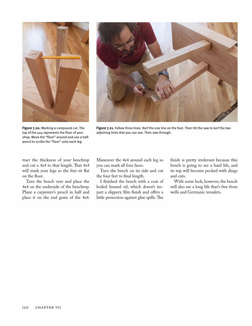
tract the thickness of your benchtop and cut a 4x4 to that length. That 4x4 will mark your legs so the feet sit flat on the floor.
Turn the bench over and place the 4x4 on the underside of the benchtop. Plane a carpenter’s pencil in half and place it on the end grain of the 4x4.
Maneuver the 4x4 around each leg so you can mark all four faces.
Turn the bench on its side and cut the four feet to final length.
I finished the bench with a coat of boiled linseed oil, which doesn’t im-part a slippery film finish and offers a little protection against glue spills. The
finish is pretty irrelevant because this bench is going to see a hard life, and its top will become pocked with dings and cuts.
With some luck, however, the bench will also see a long life that’s free from wells and Germanic invaders.
Figure 7.20. Marking a compound cut. The top of the 4x4 represents the floor of your shop. Move the “floor” around and use a half-pencil to scribe the “floor” onto each leg.
Figure 7.21. Follow three lines. Kerf the one line on the foot. Then tilt the saw to kerf the two adjoining lines that you can see. Then saw through.