Embed Size (px)
Citation preview
Well Screen Technologies
Solving your sand control challenges.
FEA Modelling of Expandable Sand Screens
Interactions with Rock Formations Ken Watson and Colin Jones; Weatherford International
SCC2009 SIMULIA Customer Conference May 18-21, 2009 – The Brewery, London, U.K.
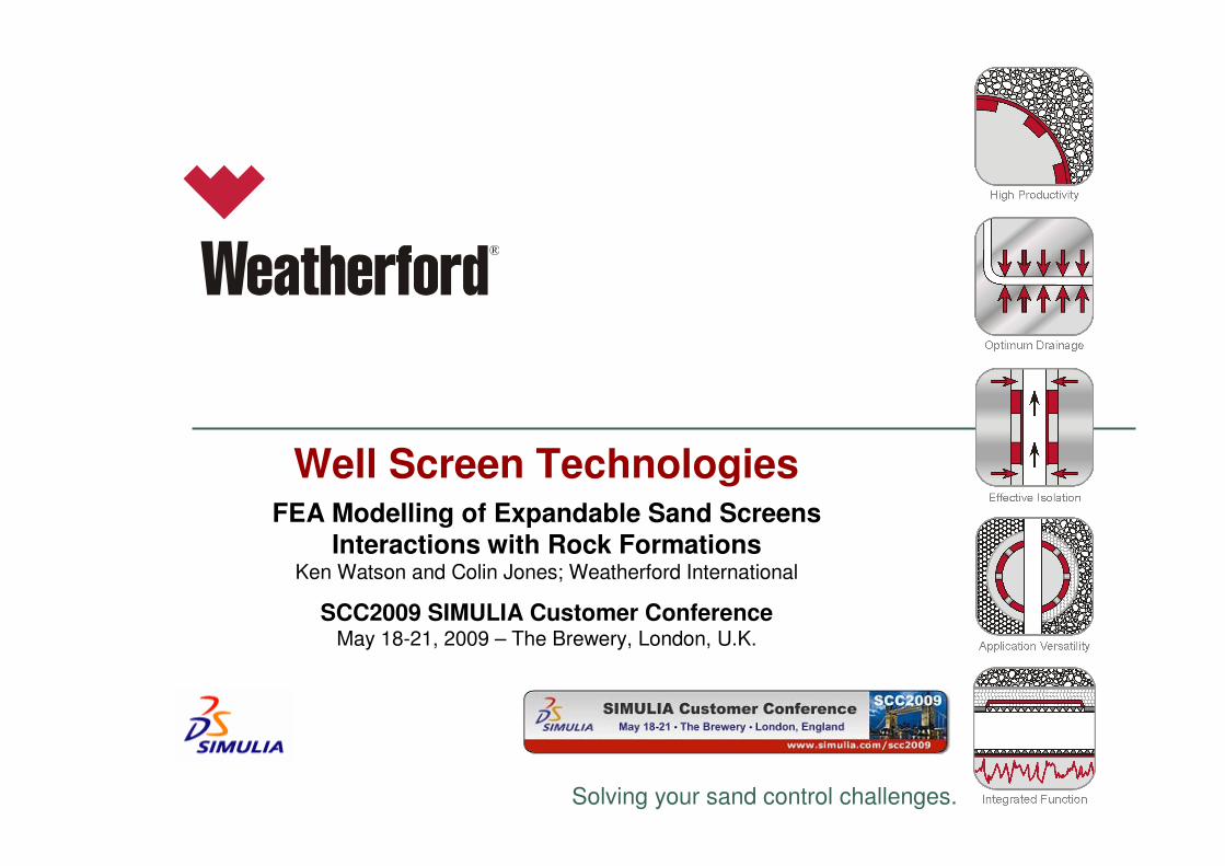
Presentation Overview
• Introduction; ESS® products / installations
• Geomechanics and ESS – EWBS example
• Meshing of slotted ESS and the subsequent Equivalent ESS
• Oilwell lifecycle and re-circularization
• Vertical-Horizontal Well Application Screening Tool
• Inclined Wellbore in a Sand Shale Sequence
• Conclusions
• Q and A
Introduction; ESS® products
Expandable Sand Screens (ESS ®) are a relatively new sand control product.
There have been approximately 800 installations worldwide (over all vendors).
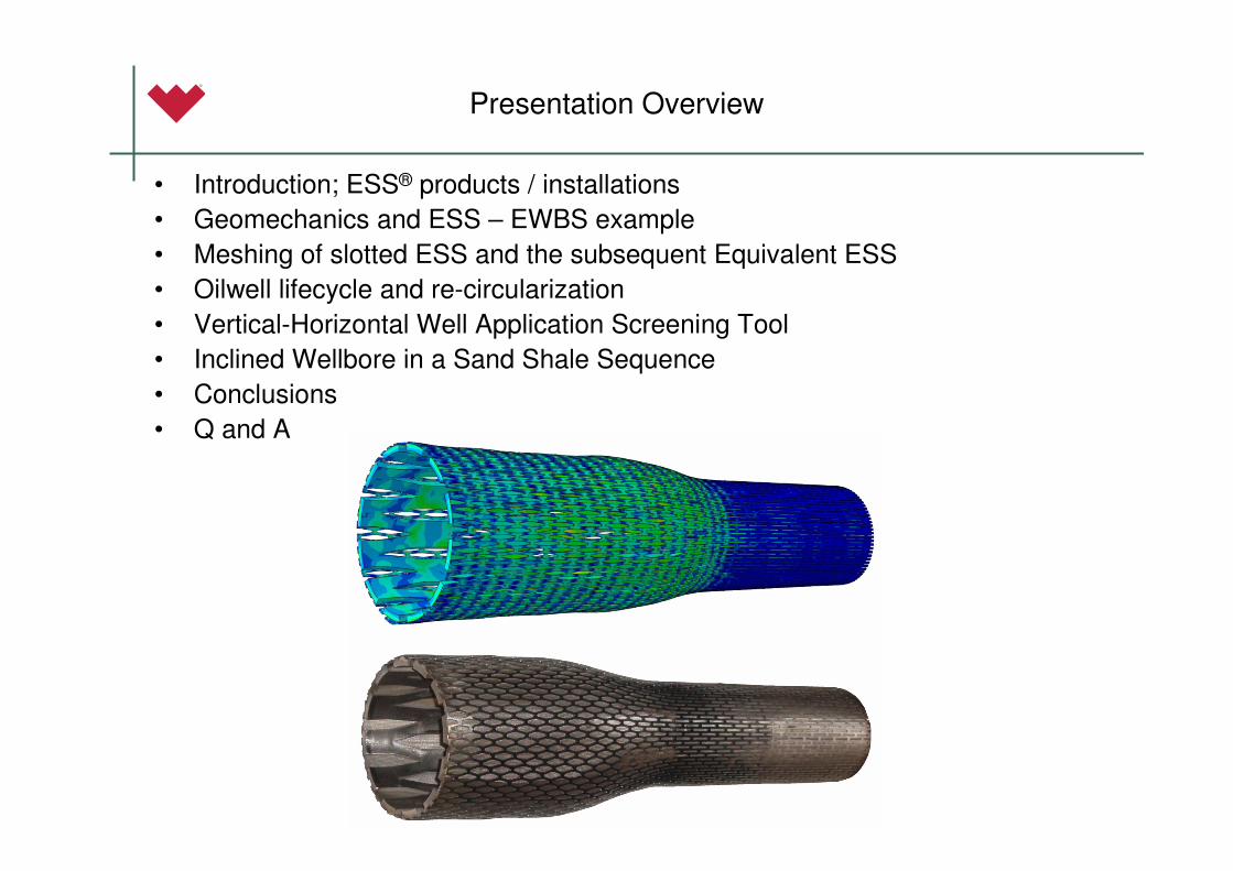
They come in two different types; a system based on slotted basepipe (shown here) and a system based on drilled basepipe.
The slotted basepipe is most common with around 600 installations since 1997.
Slotted basepipe; easy to expand into full contact with wellbore (no matter the shape). This compliant system has advantages in well productivity, sand retention capability and reliability.
Drilled basepipe; it is strong, but difficult to expand, especially in an irregular wellbore
Base Pipe Slots Open During Expansion
Maximizing Inflow Area
Outer Shroud Protects Filter
Media
Filter Media
Dutch Twill WeaveWeave Layers Slide Over
Each Other During Expansion
No change In weave aperture sizeduring the expansion process
Details of the construction of ESS
Introduction; ESS® Installations
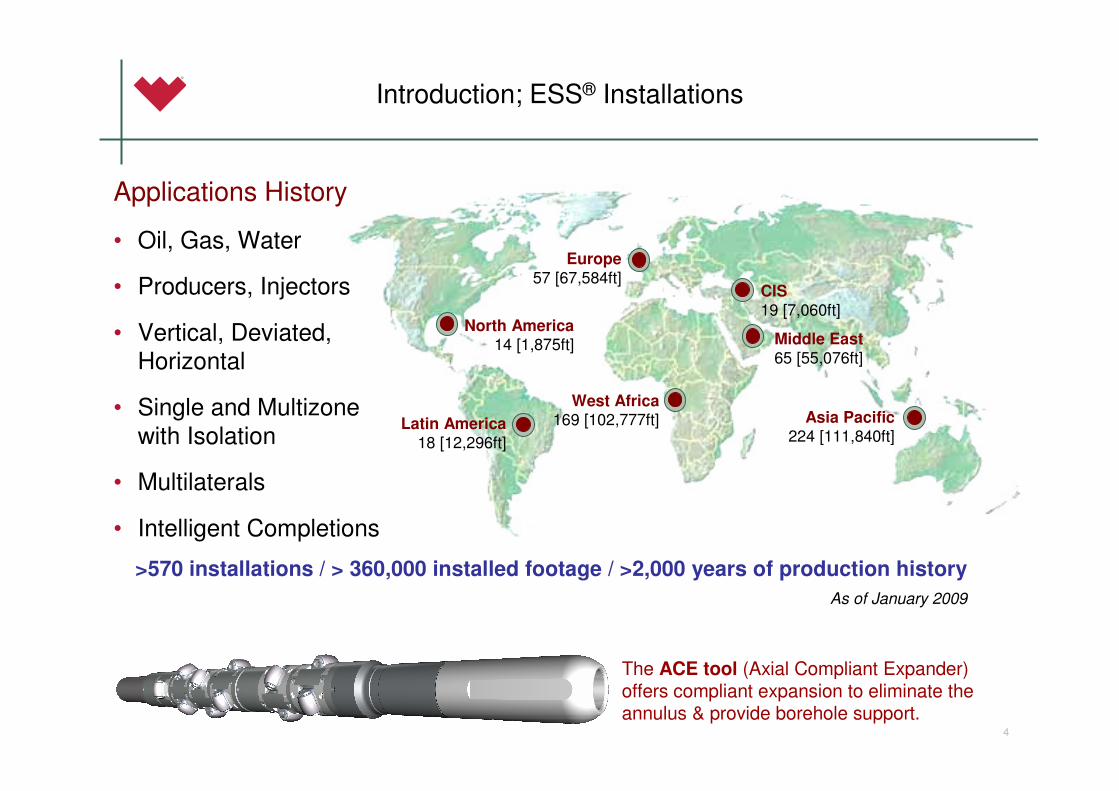
Latin America18 [12,296ft]
Europe57 [67,584ft]
West Africa169 [102,777ft]
Middle East65 [55,076ft]
North America14 [1,875ft]
CIS
19 [7,060ft]
Asia Pacific224 [111,840ft]
4
>570 installations / > 360,000 installed footage / >2,000 years of production history
Applications History
• Oil, Gas, Water
• Producers, Injectors
• Vertical, Deviated, Horizontal
• Single and Multizonewith Isolation
• Multilaterals
• Intelligent Completions
As of January 2009
The ACE tool (Axial Compliant Expander) offers compliant expansion to eliminate the annulus & provide borehole support.
Introduction; ESS® / Joint Industry Project
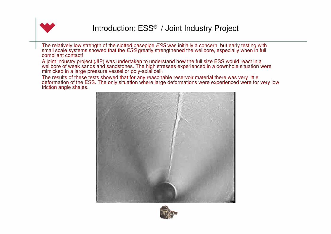
The relatively low strength of the slotted basepipe ESS was initially a concern, but early testing with small scale systems showed that the ESS greatly strengthened the wellbore, especially when in full compliant contact!
A joint industry project (JIP) was undertaken to understand how the full size ESS would react in a wellbore of weak sands and sandstones. The high stresses experienced in a downhole situation were mimicked in a large pressure vessel or poly-axial cell.
The results of these tests showed that for any reasonable reservoir material there was very little deformation of the ESS. The only situation where large deformations were experienced were for very low friction angle shales.
Geomechanics and ESS – EWBS example
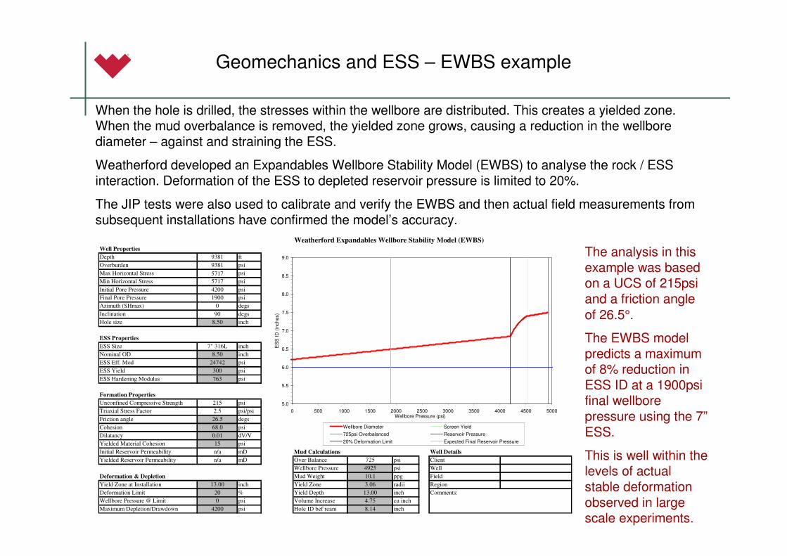
When the hole is drilled, the stresses within the wellbore are distributed. This creates a yielded zone. When the mud overbalance is removed, the yielded zone grows, causing a reduction in the wellbore diameter – against and straining the ESS.
Weatherford developed an Expandables Wellbore Stability Model (EWBS) to analyse the rock / ESS interaction. Deformation of the ESS to depleted reservoir pressure is limited to 20%.
The JIP tests were also used to calibrate and verify the EWBS and then actual field measurements from subsequent installations have confirmed the model’s accuracy.
The analysis in this example was based on a UCS of 215psi and a friction angle
of 26.5°.
The EWBS model predicts a maximum of 8% reduction in ESS ID at a 1900psi final wellbore pressure using the 7”ESS.
This is well within the levels of actual stable deformation observed in large scale experiments.
Weatherford Expandables Wellbore Stability Model (EWBS)
Well Properties
Depth 9381 ft
Overburden 9381 psi
Max Horizontal Stress 5717 psi
Min Horizontal Stress 5717 psi
Initial Pore Pressure 4200 psi
Final Pore Pressure 1900 psi
Azimuth (SHmax) 0 degs
Inclination 90 degs
Hole size 8.50 inch
ESS Properties
ESS Size 7" 316L inch
Nominal OD 8.50 inch
ESS Eff. Mod 24742 psi
ESS Yield 300 psi
ESS Hardening Modulus 763 psi
Formation Properties
Unconfined Compressive Strength 215 psi
Triaxial Stress Factor 2.5 psi/psi
Friction angle 26.5 degs
Cohesion 68.0 psi
Dilatancy 0.01 dV/V
Yielded Material Cohesion 15 psi
Initial Reservoir Permeability n/a mD Mud Calculations Well Details
Yielded Reservoir Permeability n/a mD Over Balance 725 psi Client
Wellbore Pressure 4925 psi Well
Deformation & Depletion Mud Weight 10.1 ppg Field
Yield Zone at Installation 13.00 inch Yield Zone 3.06 radii Region
Deformation Limit 20 % Yield Depth 13.00 inch Comments:
Wellbore Pressure @ Limit 0 psi Volume Increase 4.75 cu inch
Maximum Depletion/Drawdown 4200 psi Hole ID bef ream 8.14 inch
5.0
5.5
6.0
6.5
7.0
7.5
8.0
8.5
9.0
0 500 1000 1500 2000 2500 3000 3500 4000 4500 5000Wellbore Pressure (psi)
ES
S ID
(in
ches)
Wellbore Diameter Screen Yield
725psi Overbalanced Reservoir Pressure
20% Deformation Limit Expected Final Reservoir Pressure
Meshing of Slotted ESS and the subsequent Equivalent ESS
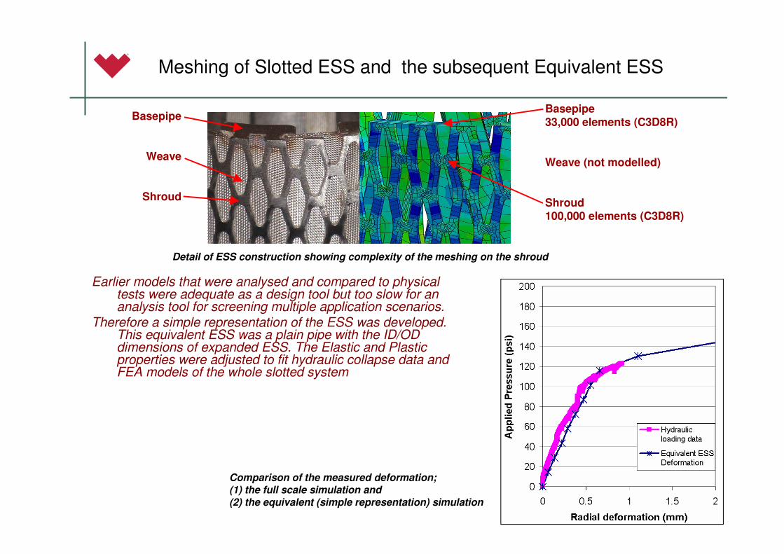
Earlier models that were analysed and compared to physical tests were adequate as a design tool but too slow for an analysis tool for screening multiple application scenarios.
Therefore a simple representation of the ESS was developed. This equivalent ESS was a plain pipe with the ID/OD dimensions of expanded ESS. The Elastic and Plastic properties were adjusted to fit hydraulic collapse data and FEA models of the whole slotted system
Basepipe
Weave
Shroud
Basepipe33,000 elements (C3D8R)
Weave (not modelled)
Shroud 100,000 elements (C3D8R)
Detail of ESS construction showing complexity of the meshing on the shroud
Comparison of the measured deformation; (1) the full scale simulation and
(2) the equivalent (simple representation) simulation
Equivalent ESS
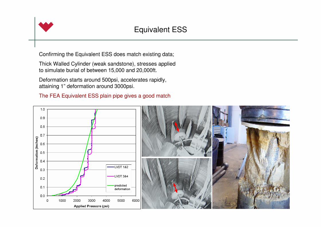
Confirming the Equivalent ESS does match existing data;
Thick Walled Cylinder (weak sandstone), stresses applied to simulate burial of between 15,000 and 20,000ft.
Deformation starts around 500psi, accelerates rapidly, attaining 1” deformation around 3000psi.
The FEA Equivalent ESS plain pipe gives a good match
Oilwell lifecycle and re-circularization
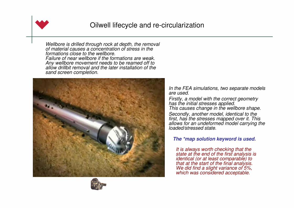
Wellbore is drilled through rock at depth, the removal of material causes a concentration of stress in the formations close to the wellbore. Failure of near wellbore if the formations are weak. Any wellbore movement needs to be reamed off to allow drillbit removal and the later installation of the sand screen completion.
In the FEA simulations, two separate models are used.Firstly, a model with the correct geometry has the initial stresses applied. This causes change in the wellbore shape.Secondly, another model, identical to the first, has the stresses mapped over it. This allows for an undeformed model carrying the loaded/stressed state.
The *map solution keyword is used.
It is always worth checking that the state at the end of the first analysis is identical (or at least comparable) to that at the start of the final analysis. We did find a slight variance of 5%, which was considered acceptable.
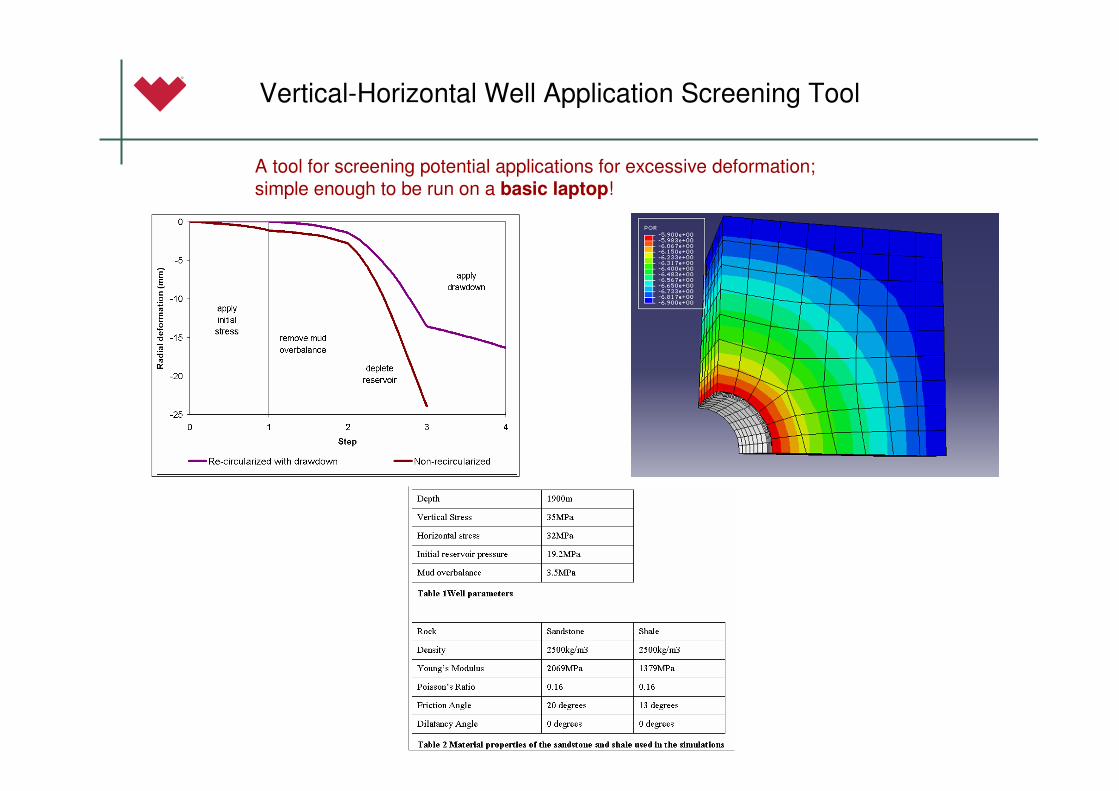
Vertical-Horizontal Well Application Screening Tool
A tool for screening potential applications for excessive deformation; simple enough to be run on a basic laptop!
Inclined Wellbore in a Sand Shale Sequence
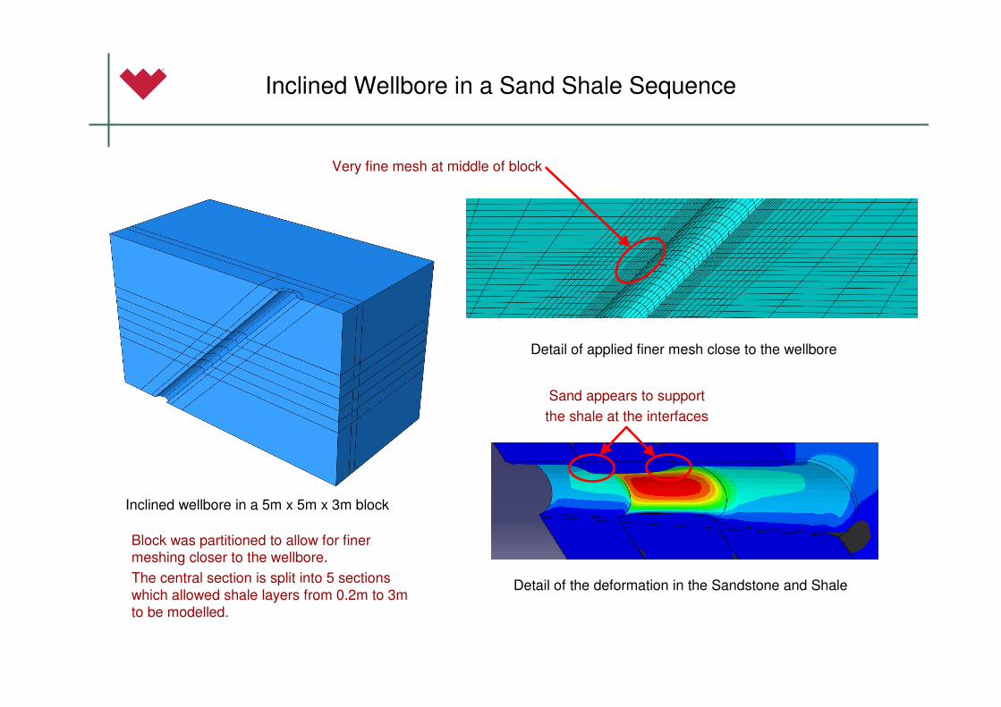
Inclined wellbore in a 5m x 5m x 3m block
Detail of applied finer mesh close to the wellbore
Detail of the deformation in the Sandstone and Shale
Block was partitioned to allow for finer meshing closer to the wellbore.
The central section is split into 5 sections which allowed shale layers from 0.2m to 3m to be modelled.
Very fine mesh at middle of block
Sand appears to support
the shale at the interfaces
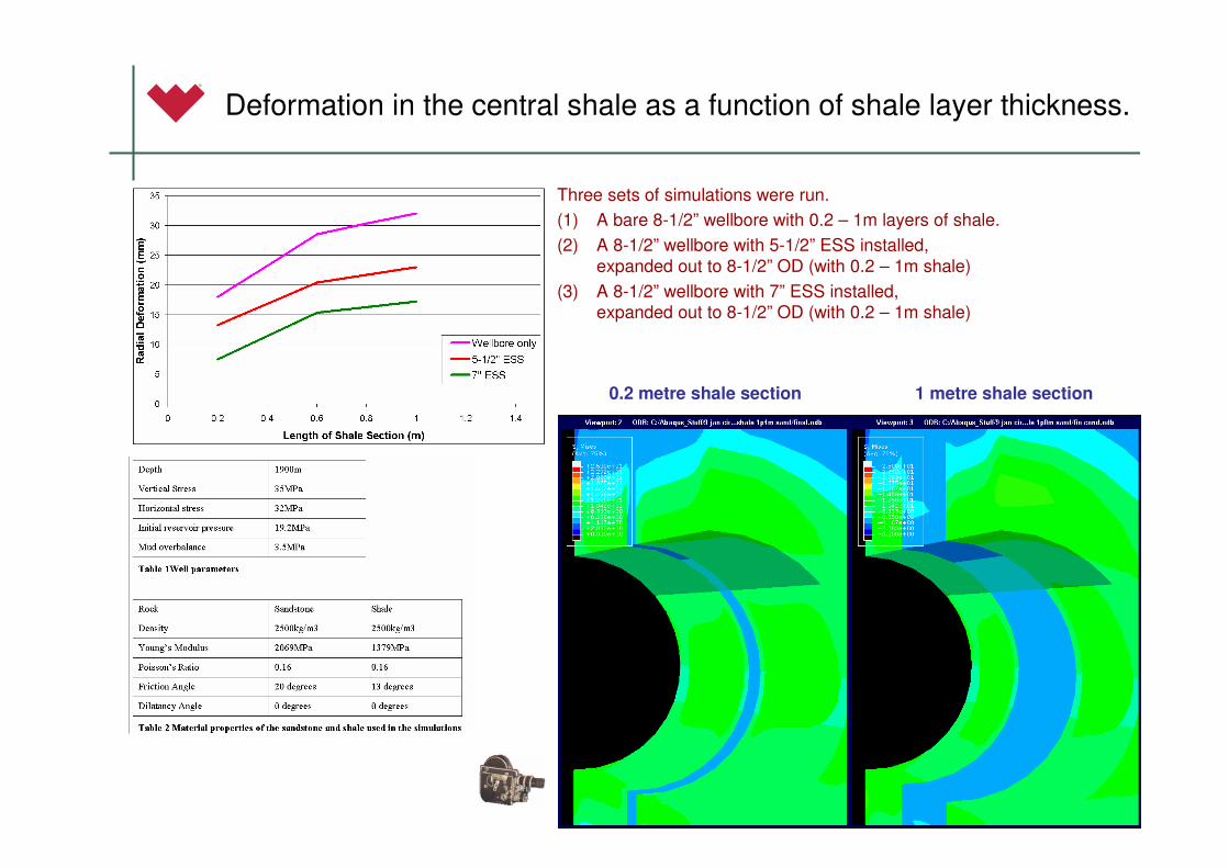
Deformation in the central shale as a function of shale layer thickness.
Three sets of simulations were run.
(1) A bare 8-1/2” wellbore with 0.2 – 1m layers of shale.
(2) A 8-1/2” wellbore with 5-1/2” ESS installed, expanded out to 8-1/2” OD (with 0.2 – 1m shale)
(3) A 8-1/2” wellbore with 7” ESS installed, expanded out to 8-1/2” OD (with 0.2 – 1m shale)
0.2 metre shale section 1 metre shale section
Wellbore with 5-1/2” ESS Wellbore with 7” ESS
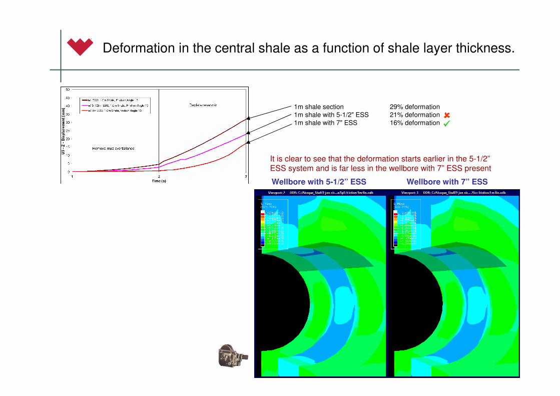
Deformation in the central shale as a function of shale layer thickness.
It is clear to see that the deformation starts earlier in the 5-1/2”ESS system and is far less in the wellbore with 7” ESS present
1m shale section 29% deformation
1m shale with 5-1/2" ESS 21% deformation
1m shale with 7" ESS 16% deformation ��������
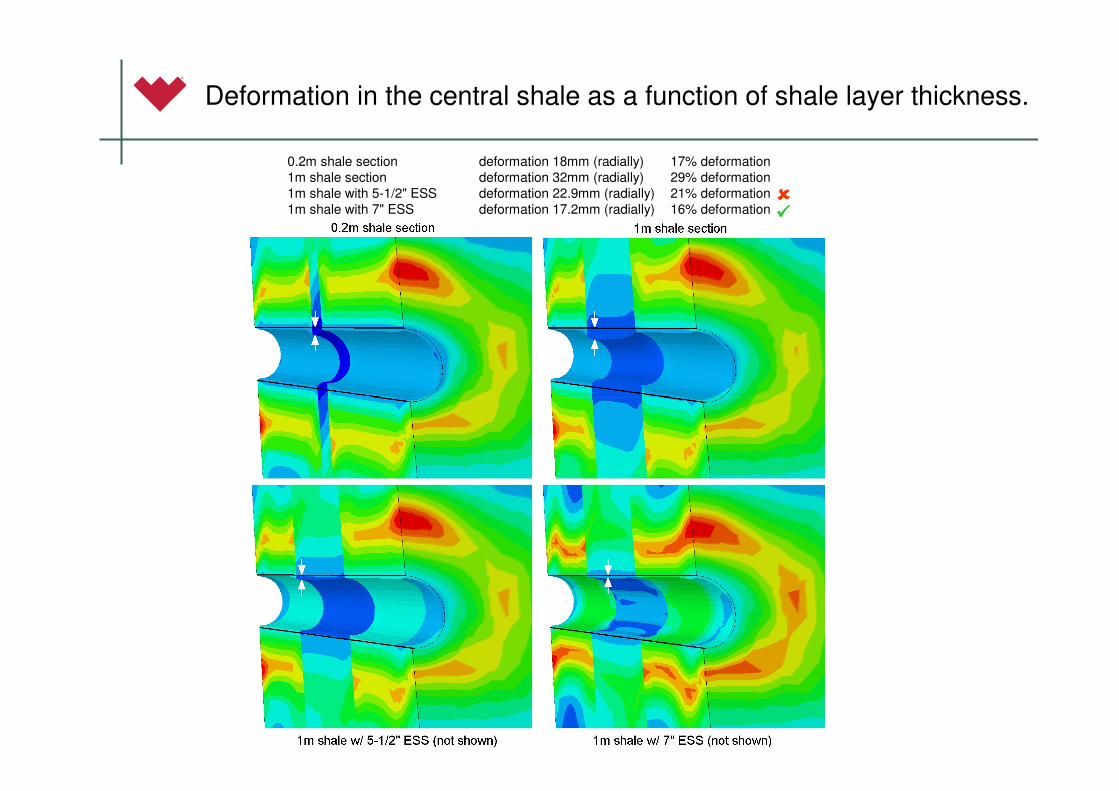
0.2m shale section deformation 18mm (radially) 17% deformation
1m shale section deformation 32mm (radially) 29% deformation
1m shale with 5-1/2" ESS deformation 22.9mm (radially) 21% deformation
1m shale with 7" ESS deformation 17.2mm (radially) 16% deformation
Deformation in the central shale as a function of shale layer thickness.
��������
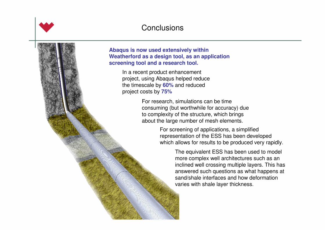
Conclusions
Abaqus is now used extensively within Weatherford as a design tool, as an application screening tool and a research tool.
For research, simulations can be time consuming (but worthwhile for accuracy) due to complexity of the structure, which brings about the large number of mesh elements.
For screening of applications, a simplified representation of the ESS has been developed which allows for results to be produced very rapidly.
The equivalent ESS has been used to model more complex well architectures such as an inclined well crossing multiple layers. This has answered such questions as what happens at sand/shale interfaces and how deformation varies with shale layer thickness.
In a recent product enhancement project, using Abaqus helped reduce the timescale by 60% and reduced project costs by 75%
Thank you for your attention
Please feel free to ask any questions