Embed Size (px)
Citation preview
Westinghouse I. L. 41-846. 1
INSTALLATION • OPERATION • MAINTENANCE
INSTRUCTIONS
TYPE SHU STATIC OUTPUT RELAY
CAUTION: It is recommended that the user of this equipment become acquainted with the information in these instructions before energizing the relay. Failure to do so may result in damage to the equipment. Before putting the relay into service, operate the relay to check the electrical connections.
APPLICATION
The type SRU static output relay is used in conjunction with a complete relaying scheme and performs a variety of functions (depending on the particular relay style). These include light indication, tripping, alarming, outputs (either contact or voltage signal) for such functions as breaker failure initiation, reclose initiation, etc., and the necessary logic circuitry for obtaining the desired operation of the particular scheme.
CONSTRUCTION
Since the SRU line of relays vary considerably as to the number of relays, lights, switches and circuit boards, no attempt will be made to describe any one particular style relay but rather to present a general explanation of the components. Some or all of these components will be found in any SRU relay.
For any one style SRU relay the user should consult the supplementary instruction leaflet for specific information such as mechanical relay and printed circuit board style information. All the pertinent drawings such as the relay logic, printed circuit board internal schematic and component location are supplied with the supplementary instruction leaflet. The supplementary I.L. number is printed on the relay nameplate.
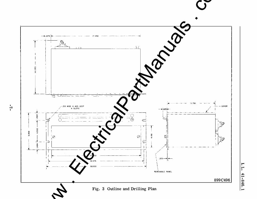
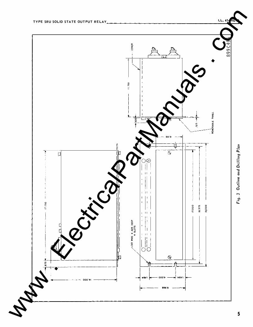
All parts are mounted on a standard 19-inch wide panel, 7 inches high (4 rack units). Edge slots are provided for mounting the chassis on a standard relay rack.
Front Chassis - On the front panel are located the various red, white and amber colored indicating lights, hand switches (for
NEW INFORMATION EFFECTIVE JUNE 1968 www . El
ectric
alPar
tMan
uals
. com
control of functions such as blocking,out-of-step trip, reclose block, etc.), and test points including the common negative.
A removable door on the front chassis covers the printed circuit modules.
Lights - All lights are incandescent and removable for replacement when necessary. The lights are energized below rated current so that they will have long life but yet provide sufficient illumination.
The lens colors are assigned according to functions. Red is used for trip indication, white for monitoring supply voltage and amber for indicating an input signal.
The light circuit consists of a thyristor which requires ' the presence of a relay input signal for approximately 10 milliseconds. The thyristor will then latch in its conducting state and will remain so until the TEST-RESET switch is hand operated momentarily.
Switches - These are hand toggle switches, usually DPST for inserting various functions in the OUT-OF-STEP circuit such as TRIP, RECLOSE BLOCK and THREE-PHASE TRIP BLOCK. One of the toggle switches marked TEST-RESET has a spring return and is used for resetting the lights as well as testing the light filament. This switch also resets the annunciator telephone relay when it is used to seal itself in.
Test Points - Also located on the front panel is a number of test jacks for use in connection with voltmeter and oscilloscope test equipment. Some of the functions that are brought out to test jacks are RECLOSE, 3-PHASE TRIP BLOCK, TRIP LOGIC, as well as relay common negative.
Printed Circuit Boards - All of the circuitry suitable for mounting on printed circuit boards are contained in an enclosure behind the door on the front panel. The printed circuit modules have a plug-in feature and are guided into position by means of slotted guides. A handle mounted on the front end of the card is used for inserting and removing the circuit. They also serve as a bumper in conjunction with the front door to prevent the board from becoming disconnected from its terminal block. The boards have test terminals and when used with a card extender (style number 849A019G01) will facilitate testing of the relay.
-2-
www . El
ectric
alPar
tMan
uals
. com
I. L. 41-846. 1
The boards have a style number stamped on them that should agree with the assembly style number listed on the relay logic drawing.
In addition, the cards are notched and corresponding plastic inserts are placed in the terminal block so that a card will not accidentally be inserted in the wrong slot location.
Rear Chassis - The rear panel consists of a hinged door which may be opened to expose the various components mounted inside for testing or inspection. In addition, one to two 32 terminal connectors are mounted on the rear panel as well as one to two 6 connection terminal strips.
The hinged door is also used to mount some of the telephone type and AR type auxiliary relays.
Inside Housing - Between the rear panel and back of the printed circuit board enclosure is mounted components such as the tripping thyristors (SCR), and pulse transformers.
Pulse Transformer - This is a low impedance two-winding iron core transformer. The primary is connected into the trip circuit so that when trip current flows a pulse is produced in the secondary and fed to the trip light indicator circuit.
Each trip circuit has a separate pulse transformer associated with it.
Auxiliary Relays - Most of these electromechanical relays are of the telephone type. Their operate time is approximately one cycle unless they are associated with an output requiring time delay on pickup or dropout. In that case the relay may be equipped with a copper slug or used in conjunction with a static timer.
Where somewhat faster operate time is required, the type AR auxiliary relay is used. Its operating time is less than � cycle.
CHARACTERISTICS
The trip circuit is isolated from the control circuit and consists of the thyristor and its protective circuitry as well as the primary of the pulse transformer. The rating of the thyristor trip circuit is 5 amps continuous and 50 amps for
www . El
ectric
alPar
tMan
uals
. com
5 cycles (83 milliseconds). The maximum forward voltage drop at 10 amps is 1.6 volts.
Where a contact output is used for tripping, it is recommended that a seal-in relay be provided for protecting the trip contacts. The trip contact can safely carry 5 amps continuous and 30 amps long enough to trip a breaker.
The SRU can be supplied for 48 and 125 Vdc control voltage and 48, 125 or 250 Vdc trip voltage.
The d.c. battery drain will depend on the particular style SRU being used. This applies to the standby condition as \vell as the operating condition. Generally, the standby drain will be less than 100 ��. In operation the drain per light is approximately 50 lil\ for 48 volt control and 20 M.A for 125 volt control systems.
OPERATION
The operation of any particular SRU relay can best be understood by referring to the supplementary instruction leaflet which is provided for each relay. A logic drawing has been made up in order to follow the path of each function from the input to its final destination in the relay. In addition, an internal schematic and component location drawing for each circuit board is also included in the supplementary instruction leaflet which enables the user to make specific tests or trouble shoot.
The supplementary instruction leaflet number is printed on the nameplate information with each relay.
For those users not generally acquainted with logic circuit notation or with device symbols of those components used in the SRU drawing, it is recommended that a. copy of vJestinghouse instruction leaflet I.L. 41-000.1 entitled SYHBOLS FOR SOLID STATE PROTECTIVE RELAYING be consulted.
CAUTION: Do not remove or insert printed circuit modules while the relay is energized.
SETTINGS
All toggle switches should be switched to their desired position prior to placing the relay in service.
-4-
,
www . El
ectric
alPar
tMan
uals
. com
I. L. 41-846. 1
If any variable timer circuit boards are. used they should be set for the required time and the setting knob locked in position by means of the locking tab.
INSTALLATION
The SRU relay is generally supplied in a cabinet or on a relay rack as part of a complete system. The location must be free from dust, excessive humidity, vibration, corrosive fumes or heat. The maximum temperature around the chassis must not exceed 60°C.
ACCEPTANCE
It is recommended that an acceptance check be applied to the relay to insure it is in proper working order. A test drawing containing a test circuit and a test table is included with the supplementary instruction leaflet and is provided for this purpose.
MAINTENANCE
The components of the SRU are operated well within their ratings and under normal conditions should give long trouble free service.
The indicating lights may be checked by operating the test reset switch. They are of the plug-in base replaceable type.
If the relay gives in indication of trouble, the test acceptance check is recommended for locating the source of trouble. The printed circuit board extender and the printed circuit board internal schematic is helpful in locating and replacing a defective component.
RENEWAL PARTS
Repair work can be done most satisfactorily at the factory. However, interchangeable parts can be furnished to the customers who are equipped for doing the repair work. When ordering parts, always give the complete nameplate data, and component Style No. given in the Electrical Parts List.
-5-
www . El
ectric
alPar
tMan
uals
. com

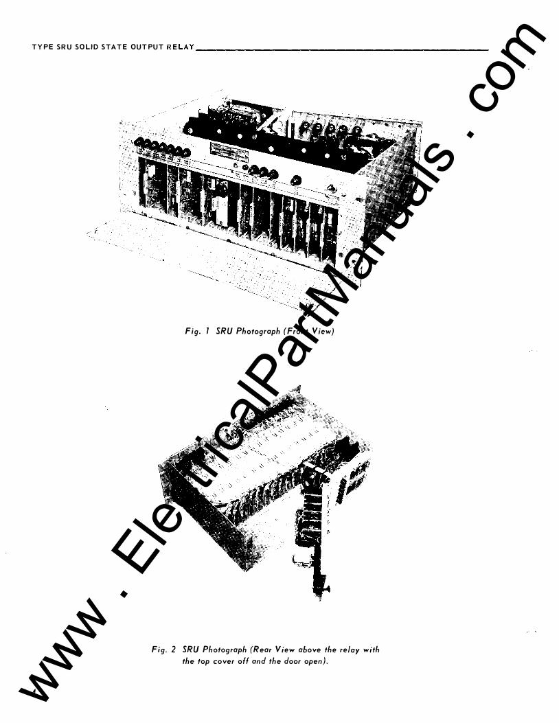
Fig. 1 SRU Photograph (Front View)
Fig 2 SRU Photograph (Rear View taken above the relay with the top cover off and the door open).
- 6-www . El
ectric
alPar
tMan
uals
. com
I -l I
.875 1.-- ·- 17 250 ---
- ----------- -+1
II� II ll �I
I
Ll =
� · · �
/-.313 WIDE X .625 DEEP
/ _l 4 SLOTS .- V o-
------- ---- -- -o
11. o=-=-- � = --= == = =:__ __ - = -� = =---,{_}, --- ---
-- --- - ---- - - --�
0 0 0 ..
0
17.000 18.375 -- -
-- -19,000
-T ., � ..
- l
\ "'-�� . REMOVABLE PANEL
Fig. 3 Outline and Drilling Plan
899C496
1-4 . tot .
� ,_.. I 00 � (j) . ,_..
www . El
ectric
alPar
tMan
uals
. com

WESTINGHOUSE ELECTRIC CORPORATION RELAY-INSTRUMENT DIVISION NEWARK, N. J.
Printed in U.S.A. www . El
ectric
alPar
tMan
uals
. com
INSTALLATION Westinghouse I .L. 41-B46.1B
• OPERATION • MAINTENANCE
INSTRUCTIONS
TYPE SRU SOLID STATE OUTPUT RELAY
CAUTION: It is recommended that the user of this
equipment become acquainted with the
information in these instructions before
energizing the relay. Failure to do so
may result in damage to the equipment.
Before putting the relay into service,
operate the relay to check the electrical
connections.
APPLICATION
The type SRU static output relay is used in con
junction with a complete relaying scheme and per
forms a variety of functions (depending on the
particular relay style). These include light indica
tion, tripping, alarming, outputs (either contact or
voltage signal) for such functions as breaker failure
initiation, reclose initiation, etc., and the necessary
logic circuitry for obtaining the desired operation of
particular scheme.
CONSTR UCTION
Since the SRU line of relays vary considerably as to
the number of relays, lights, switches and circuit
boards, no attempt will be made to describe any one
particular style relay but rather to present a general
explanation of the components. Some or all of these
components will be found in any SRU relay.
For any one style SRU relay the user should consult
the supplementary instruction leaflet for specific
information such as mechanical relay and printed
circuit board style information. All the pertinent
drawings such as the relay logic, printed circuit
board internal schematic and component location
are supplied with the supplementary instruction
leaflet. The supplementary I. L. number is printed
on the relay nameplate.
All parts are mounted on a standard 19-inch wide
panel, 7 inches high (4 rack units). Edge slots
are provided for mounting the chassis on a standard
relay rack.
SUPERSEDES I.L. 41-846.1A *Denotes change from superseded issue.
* Front Chassis
On the front panel are located the various red and
amber colored indicating lights, toggle switches (for
control of functions such as blocking, out-of-step
trip, etc.), and test points including the common
negative.
A hinged and removeable door on the front chassis
covers the printed circuit module housing.
Lights
All lights are incandescent and removable for re
placement when necessary. The lights are energized
belo·w rated current so that they will have long life
but yet provide sufficient illumination.
The lens colors are assigned according to functions.
Red is used for trip indication, and amber for in
dicating a non-tripping input signal.
The light circuit consists of a thyristor which re
requires the presence of a relay input signal for
approximately 1 millisecond. The thyristor will
then latch in its conducting state and will remain
on, allowing the alarm contacts to close for a min
imum of 150 milliseconds. The indicator module has
an option for providing a seal-in feature for the
alarm relay.
* Switches
These are hand toggle switches, usually DPST for
inserting various functions in the OUT-OF-STEP
circuit such as TRIP and THREE-PHASE TRIP
BLOCK. One of the toggle switches marked TEST
RESET has a spring return and is used for resetting
the lights as well as testing the light filament. This
switch also resets the annunicator telephone relay
when it is used to seal itself in. A locking tab
feature prevents accidental operation of the func
tion switches.
Test Points
Also located on the front panel are a number of test
jacks for use in connection with voltmeter and
EFF ECTIVE SEPTEMBER 1973 www . El
ectric
alPar
tMan
uals
. com

TYPE SRU SOLID STATE OUTPUT RELAY----------------------------
oscilloscope test equipment. Some of the functions
that are brought out to test jacks are RECLOSE, 3-
PHASE TRIP BLOCK, TRIP LOGIC, as well as
relay common negative.
Printed Circuit Boards
All of the circuitry suitable for mounting on printed
circuit boards are contained in an enclosure behind
the door on the front panel. The printed circuit
modules have a plug-in feature and are guided into
position by means of slotted guides. A handle
mounted on the front end of the card is used for
inserting and removing the circuit. They also serve
as a bumper in conjunction with the front door to
prevent the board from becoming disconnected
from its terminal block. The boards have test ter
minals and when used with a card extender (style
number 849A534G01) will facilitate testing of
the relay.
The boards have a style number stamped on them
that should agree with the assembly style number
listed on the relay logic drawing.
In addition, the cards are notched and corresponding
plastic inserts are placed in the terminal block so
that a card will not accidentally be inserted in the
wrong slot location.
Rear Chassis
The rear panel consists of a hinged door which may
be opened to expose the various components mounted
inside for testing or inspection. In addition, one
or two 32 terminal connectors are mounted on the
rear panel as well as one or two 6 connection ter
minal strips.
The hinged door is also used to mount some of the
telephone type and AR type auxiliary relays.
Inside Housing
Between the rear panel and back of the printed cir
cuit board enclosure is mounted components such as
the tripping thyristors and pulse transformers.
Pulse Transformer
This is a low impedance two-winding iron core
* transformer. The primary is connected into the trip
circuit so that when trip current flows a pulse is
produced in the secondary and fed to the trip light
indicator circuit.
2
Each trip circuit has a separate pulse transformer
associated with it.
Auxiliary Relays
Most of these electromechanical relays are of the
telephone type. Their operate time is approximately
one cycle unless they are associated with an output
requiring time delay on pickup or dropout. In that
case the relay may be equipped with a copper slug
or used in conjunction with a static timer. Contact
capacity is 4 amps, 150 watts, w ith a resistive load.
CHARACTER IS TICS
The trip circuit is isolated from the control circuit
and consists of the thyristor and its protective
circuitry as well as the primary of the pulse trans
former. The rating of the thyristor trip circuit is 5
amps continuous and 50 amps for 5 cycles (83 milli
seconds). The maximum forward voltage drop at
*the trip terminals is 3.0 volts at 10 amps, 5.0 volts
at 20 amps, and 6.0 volts at 30 amps. The time
required to actuate the thyristor upon the occurance
of a trip signal into the SR U is approximately 1
millisecond.
When a contact output is used for breaker tripping,
a contactor switch is provided to seal in the cont
acts and protect them. The trip contact can safely
carry 5 amps continuous and 30 amps long enough
to trip a breaker.
The SRU can be supplied for 48 and 135 Vdc control
voltage and 48, 125 or 250 Vdc trip voltage.
The d.c. battery drain will depend on the particular
style SRU being used. This applied to the standby
condition as well as the operating condition. Gen
erally, the standby drain will be less than 1 00 MA.
In operation the drain per light is approximately 50
MA for 48 volt control and 20 MA for 125 volt control
systems.
OP ERATION
The operation of any particular SRU relay can best
be understood by referring to the supplementary
instruction leaflet which is provided for each relay.
A logic drawing has been made up in order to follow
the path of each function from the input to its final
destination in the relay. In addition, an internal
schematic and component location drawing for each
www . El
ectric
alPar
tMan
uals
. com

TYPE SRU SOLID STATE OUT PUT RELAy ------------------------_..:.:'·�L..:... �4..:..1·.:.84..:.:6:.:.· :.::.1B
circuit board is also included in the supplementary
instruction leaflet which enables the user to make
specific tests or trouble shoot.
The supplementary instruction leaflet number is
printed on the nameplate of each relay.
For those users not generally acquainted with logic
circuit notation or with device symbols of those
components used in the SRU drawing, it is recom
mended that a copy of Westinghouse instruction
leaflet I.L. 41-000.1 entitled SYMBOLS FOR SOLID
STATE PROTECTIVE RELAYING be consulted. For
out-of-step logic, refer to instruction leaflet I.L.
40-211.
CAUTION: Do not remove or insert printed circuit
modules while the relay is energized.
SETTINGS
All toggle switches should be switched to their
desired position to placing the relay in service.
If any variable timer circuit boards are used they
should be set for the required time and the setting
knob locked in position by means of the locking tab.
INSTALLATION
The SRU relay is generally supplied in a cabinet or
on a relay rack as part of a complete system. The
location must be free from dust, excessive humidity,
vibration. corrosive fumes or heat. The maximum
temperature around the chassis must not exceed
55°C.
ACCEPTANCE
It is recommended that an acceptance check be
applied to the relay to insure it is in proper working
order. A test drawing containing a test circuit and
a test table is included with the supplementary
instruction leaflet and is provided for this purpose.
MAINTENANCE
The components of the SRU are operated well within
their ratings and under normal conditions should
give long trouble free service.
The indicating lights may be checked by operating
the test reset switch. They are of the plug-in base
replaceable type.
If the relay gives an indication of trouble, the test
acceptance check is recommended for locating the
source of trouble. The printed circuit board extender
and the printed circuit board internal schematic is
helpful in locating and replacing a defective com
ponent. The internal schematic drawing numbers
are shown on the logic diagram for the particular
SRU.
RENEWAL PAR TS
Repair work can be done most satisfactorily at the
factory. However. interchangeable parts can be
furnished to the customers who are equipped for
doing repair work. When ordering parts, always
give the complete nameplate data, and component
Style No. given in the Electrical Parts List.
3 www . El
ectric
alPar
tMan
uals
. com
TYPE SRU SOLID STATE OUTPUT RELAY-----------------------------
4
Fig. 1 SRU Photograph (Front View}
Fig. 2 SRU Photograph (Rear View above the relay with
the top cover off and the door open).
www . El
ectric
alPar
tMan
uals
. com
TYPE SRU SOLID STATE OUTPUT RELAY __________________ ..:..:.•·:.:L·_:
4..:....
1·:..:84
.::.6.
�18
0 "' N
!:::
I I l I I I
,I 'I I
J
II I
I l�L-..----------w-
1'-
-r-1 '-t------ OOO't-1 ---�
=
n. UJ UJ 0 "' ...... "'o "'-' . .,
0� I iII 1 II I
I II I
1 II I
" .. I II I UJ lilll
-"" 0 0
-ss1·v-
0 ., 0 0 .. 0 0 "' 0 t: � �
�----ffi------(§)- --ffi--�___.__ �
�:�,,,_��� �-- 896'9 ·I
.. 0 "0
c: 0 C1l .:: .... :;, 0
5 www . El
ectric
alPar
tMan
uals
. com

www . El
ectric
alPar
tMan
uals
. com

www . El
ectric
alPar
tMan
uals
. com

WESTINGHOUSE ELECTRIC CORPORATION RELAY-INSTRUMENT DIVISION NEWARK, N. J.
Printed in U.S.A. www . El
ectric
alPar
tMan
uals
. com