Embed Size (px)
Citation preview
Westinghouse Non-Proprietary Class 3LTR-NRC-08-9 NP-Enclosure
"Westinghouse Presentation on Westinghouse Fuel PerformanceUpdate Meeting" (Slide Presentations of February 20-21, 2008) and
Associated Material (Non-Proprietary)
Westinghouse Electric CompanyP.O. Box 355
Pittsburgh, Pennsylvania 15230-0355
0 © 2008 Westinghouse Electric Company LLCAll Rights Reserved
©2008 Westinghouse Electric .... m •py ..CAll Rights Reserved
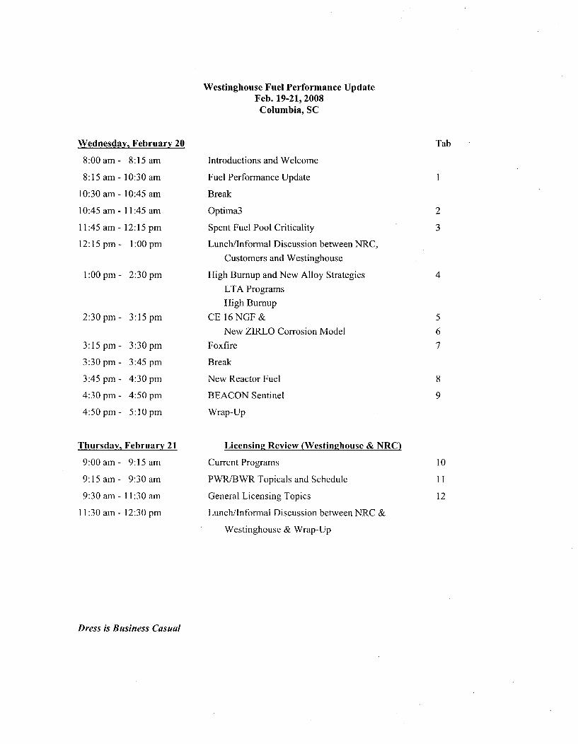
Westinghouse Fuel Performance UpdateFeb. 19-21, 2008Columbia, SC
Wednesday, February 20 Tab
8:00 am -
8:15 am -
10:30 am -
10:45 am -
11:45 am -
12:15 pm -
8:15 am
10:30 am
10:45 am
11:45 am
12:15 pm
1:00 pm
1:00 pm - 2:30 pm
2:30 pm- 3:15 pm
3:15 pm -
3:30 pm -
3:45 pm -
4:30 pm -
4:50 pm -
3:30 pm
3:45 pm
4:30 pm
4:50 pm
5:10 pm
Introductions and Welcome
Fuel Performance Update
Break
Optima3
Spent Fuel Pool Criticality
Lunch/Informal Discussion between NRC,
Customers and Westinghouse
High Burmup and New Alloy Strategies
LTA Programs
High Burnup
CE 16 NGF &
New ZIRLO Corrosion Model
Foxfire
Break
New Reactor Fuel
BEACON Sentinel
Wrap-Up
Licensing, Review (Westinghouse & NRC)
Current Programs
PWR/BWR Topicals and Schedule
General Licensing Topics
Lunch/Informal Discussion between NRC &
Westinghouse & Wrap-Up
1
2
3
4
5
6
7
8
9
10
11
12
Thursday, February 21
9:00am- 9:15 am
9:15am- 9:30 am
9:30 am- 11:30 am
11:30 am- 12:30 pm
Dress is Business Casual
Fuel Performance Update &Westinghouse Flawless Fuel
Program
Westinghouse/NRC Fuel Update MeetingColumbia, SCFeb 20,2008
Slide 1 (OwestZi'bhus
Current Westinghouse LWR Product Lines(Worldwide)
a, c
Slide 2 Slide 2iWesflnghouse
Topics
* BWR Fuel Performance Summary* PWR Fuel Performance Summary
* Post Irradiation Exam Summary
" Westinghouse Flawless Fuel Program" Key Design & Manufacturing Improvements
Slide 3 WestIn~tiouse
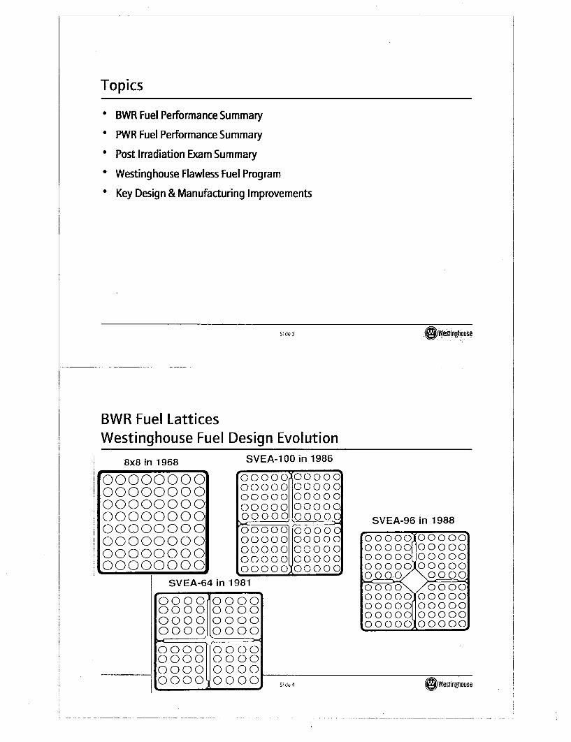
BWR Fuel LatticesWestinghouse Fuel Design Evolution
8x8 in 1968
00000000000000000000000000000000000000000000000000000000L0000000o
SVEA-100 in 1986
000000000000000 0000000000 0000000000 00000000 00 100OC00000 000000000 0000000000 0000000000O000000oooo 0oooo
1981• I
SVEA-96 in 1988
00000 0000000000 0000000000 00000100000 00000000.0 00000000 000000000 0000000000 0000000000 0000000000 OOooc
SVEA-64 in
000 000000000110000000 00 00000
ooooLo ooo0000 00000000 100000000 100000000 0000
S~de 4 We~1inghouse
Slide 4(a ftlighouse
Leaking Fuel Mechanisms (Primary) - Worldwide BWRFuel Rods
a, c
I Slide 5 ww"Ouse
BWR Leaking Fuel Rods by Yeara, b.c
Slide 6S WeSinghouse
BWR Leaking Fuel Summarya, C
Slide 7
LK3 Cladding - In-Reactor Burnup Experience
7 a, b,c
Slide 8 ~We~fln~Irnuse
Slide 8 OG Weslinghouse
Two-Life Rods [ Sa, c
a, b, c
(&WestmfhuseSlide 9
Two-Life Rods Power Historya, b,c
SIi~1~ 10
~We~trn~ ouseeWeslingahse
qlidi 1in
CladdingCladding
Corrosion - Mid-span Oxide Thickness byType
a, b, c
Slide 11
Rod Growth By Cladding Typea, bc
Slide 12dWevinghouse
BWR Fuel Performance Channela, c
Slide 13
Channel Corrosiona, b,c
Slide 14 S 1Wetinghouse
Channel Hydrogen Pick-Upa, b, c
Slide 15 (Wesorouse
Channel Bow & Irradiation Induced Growtha, c
Slide 16 ~~~We~1ingflouse
Slide 16 O~wesing~ouSe
Channel Growtha, b,c
Slide 17 OWesinRIhouse
Channel Bow in Asymmetric Latticea,b,c
rSlide I 8Si Wevinghouse
Channel Bow in Symmetric Latticea, b,c
Slide 19 Westin•tmuse
Topics
* BWR Fuel Performance Summary
" PWR Fuel Performance Summary
* Post Irradiation Exam Highlights
* Westinghouse Flawless Fuel Program
" Key Design & Manufacturing Improvements
Slide 20 Owesiingtlouse
I
Leaking Fuel Mechanisms- Worldwide PWR Fuel Rods(1995 - 2007)
a, c
Slide 21 (A Wesina']ouse
Leaking Rods - Global Performance, PWR & BWRa, c
Slide 22eWesting.house
Leaking Rods - Global Performance, PWR & BWRa, c
Slide 23 (Dwwstnvouse
PWR Fuel Performance a, c
Slide 24 (~~We~tlngt1ouse
Slide 24 OWevinghouse
Westinghouse "OFA" Grid Designs-- a,i
Slide 25
Westinghouse-NSSS 15, 17 Low Pressure Drop GridDesigns
a, c
Slide 26
CE-NSSS1 4x1 4 & 1 6x1 6 Grid Support Evolution ac
Slide 27 (OWWsIngtiOUSe
Debris Performance
" Three Debris mitigation systems are used as a result of product evolution indifferent organizations.
" Westinghouse NSSS-Debris Filter Nozzle (DFBN) + Low Profile Debris catching grid (P-Grid) below
the bottom inconel grid + long end plug-Pre-oxidized cladding offered as an option
" CE-NSSS
-High profile bottom grid attached to bottom nozzle.
-Long end plugs* BWR-NSSS
-Debris filter nozzle (Triple Wave) - chevron fins; no line of sight throughnozzle
Slide 28 0 Wesnflngouse
Westinghouse-NSSS Debris Mitigation System -
DFBN, P-Grid and Coated Claddinga, c
Slide29 (Owestinghouse
CE-NSSS Debris Mitigation System -
Guardian Grid and Long End Pluga, b,c
ýlide 30S~id 30 eftinkaouse
BWR-NSSS Debris Mitigation System - Triple Wavea, b,C
Slide 31 O Wesinglhouse
Field Performance of Debris Mitigation Systems
r-I ab,c
Slide 32 We~tInghausa
Slide 32OWeslinghause
Topics
* BWR Fuel Performance Summary* PWR Fuel Performance Summary
" Post Irradiation Exam Highlights
* Westinghouse Flawless Fuel Program" Key Design & Manufacturing Improvements
Slide 33 OWeslinghouse
Westinghouse Proprietary Class 2
Summary of Fretting Related Exam Resultsa, c
Slide 34 WesTinghouse
Slide 340 Wevinghouse
CE-NSSS - 14x14 TURBO Producta, c
Slide 35 (awesngrnuse
UT Results-- a, c
Slide 36SWestinghouse
14x1 4 TURBO RCA Resultsa, c
Slide 37 (swestingficusie
Westinghouse-NSSS -1 7x1 7 RFA leaking rodsa, c
Slide 38 " S~ide38 G wevtingflouse
17 RFA Debris Leakera, c
Slide 39 (OWestinghouse
17 RFA Debris Leakera, c
Slide 40 deWestinghouse
17 RFA Assembly-I a, c
Slide41 (s~wesingtiouse
Westinghouse-NSSS 1 5x1 5 V5H, OFAa,b,c
Slide 42i 4Wetingouse
Assembly HH83 G-5a,c
Slide 43 GWeftUouse
Assembly HH83 G-6a, c
Slide,144We1ihO e
Assembly HH83a, bc
Slide45 GWestinghouse
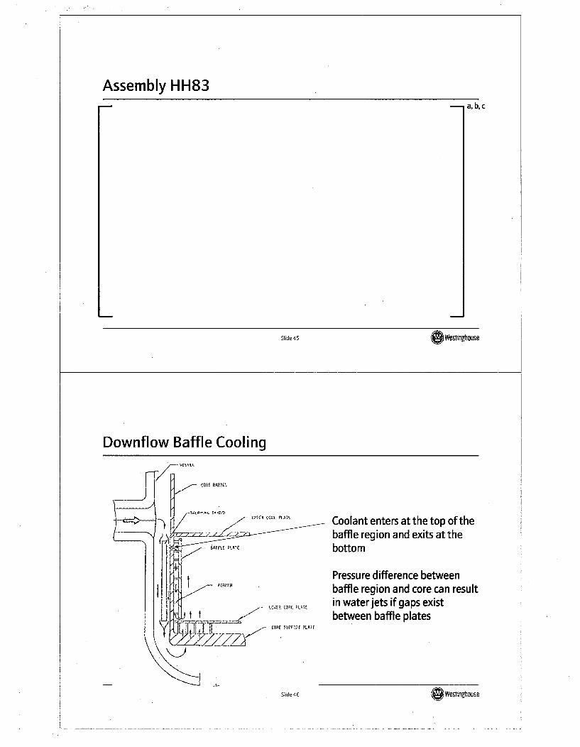
Downflow Baffle Cooling
CORE DAREII
- Cu'pRq CCRE PIAIE Coolant enters at the top of thebaffle region and exits at thebottom
Pressure difference betweenbaffle region and core can result
IIR CORE 0 in water jets if gaps existbetween baffle plates
COt SRIPPIE~ ýLAAF
Sild 46Slide0 46(Westingtouse
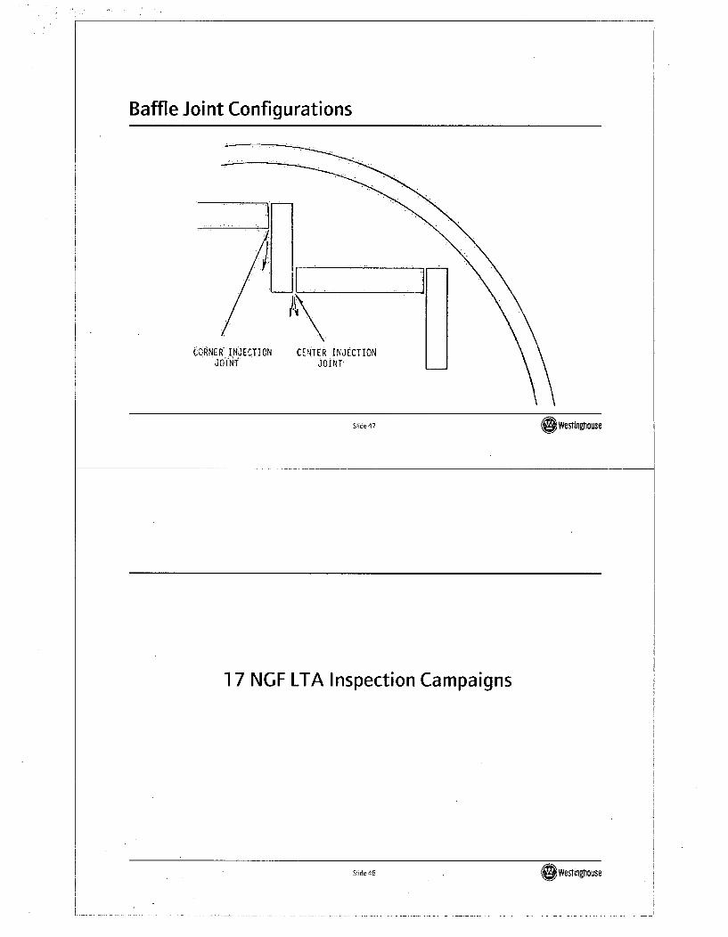
Baffle Joint Configurations
CORNER INJECTION CENTER INJECTIONJOINT JOINT
Slide47 bWesflnghiouse
1 7 NGF LTA Inspection Campaigns
Slide48 d 4Weslinghouse
1 7 NGF Product Featuresa, b,c
I-
OWestiloghouse
Catawba 1 NGF Examination Resultsa, b,c
SI~de 50 We&tinghause
Slide 50eftlinghouse
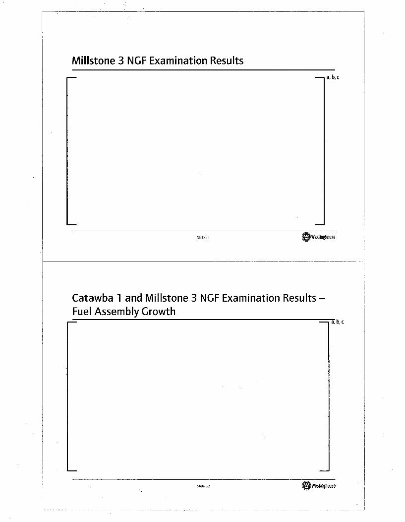
Millstone 3 NGF Examination Results
a,b,c
Slide 51 OWestinghouse
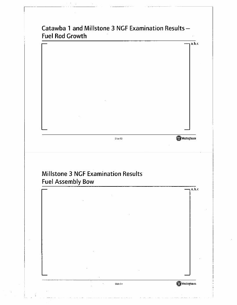
Catawba 1 and Millstone 3 NGF Examination Results -Fuel Assembly Growth
I
a. D,c
Slide 52Si Wesfingahouse
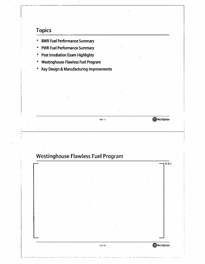
Catawba 1 and Millstone 3 NGF Examination Results -
Fuel Rod Growtha,b,c
Slide 53 OWestinghouse
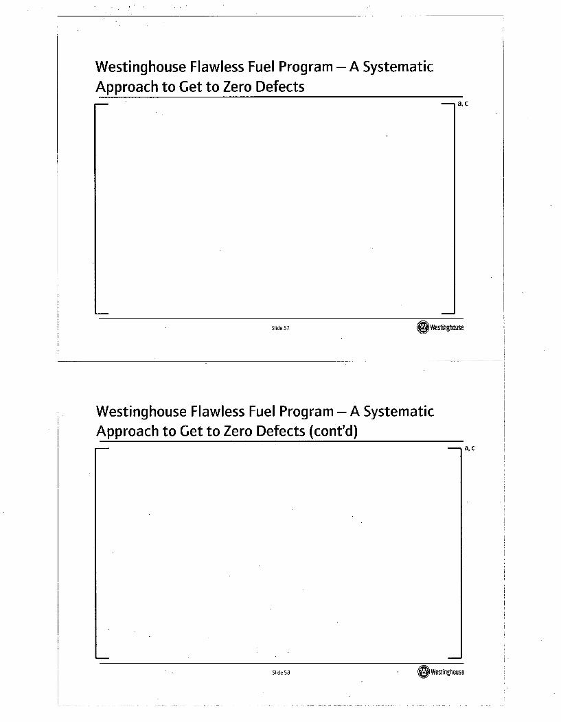
Millstone 3 NGF Examination ResultsFuel Assembly Bow
a,b,c
Slide 54lWeslinghouse
Topics
" BWR Fuel Performance Summary
" PWR Fuel Performance Summary
* Post Irradiation Exam Highlights
" Westinghouse Flawless.Fuel Program
* Key Design & Manufacturing Improvements
Slide 55 OWestinghouse
Westinghouse Flawless Fuel Programa, b,c
r, fidý V60 Wesinghouse
Westinghouse Flawless Fuel Program - A SystematicApproach to Get to Zero Defects
CaI
Slide 57 OWesingfrnuse
Westinghouse Flawless Fuel Program - A SystematicApproach to Get to Zero Defects (cont'd)
a, cac
Slide 58Sd 8Weinghouse
Topics
" BWR Fuel Performance Summary
" PWR Fuel Performance Summary
" Post Irradiation Exam Highlights
" Westinghouse Flawless Fuel Program
* Key Design & Manufacturing Improvements
Slide 59 ( We in•flouSe
Debris Fretting Improvement Projectsac
Slide 60 OWeging.tause
Original vs. Alternate P-Gridac
Slide 61 '(Westimnouse
Preventing Future Crud/Corrosion Failures-I a, C
Slide 62 (Westingthouse
j
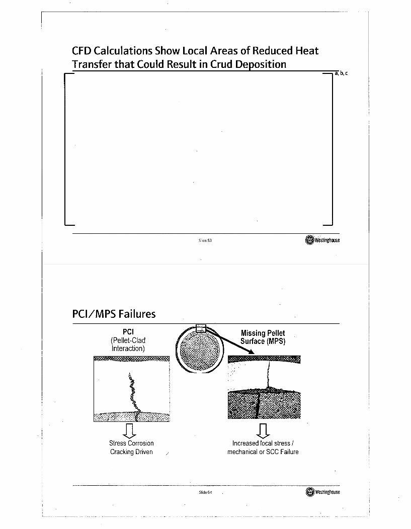
CFD Calculations Show Local Areas of Reduced HeatTransfer that Could Result in Crud Deposition
I
a, D, c
Slide 63 Westinghouse
PCI/MPS Failures
PCI(Pellet-CladInteraction)
Missing PelletSurface (MPS)
Increased local stress /mechanical or SCC FailureCracking Driven
Slide 64S 6Wevtnghouse
L
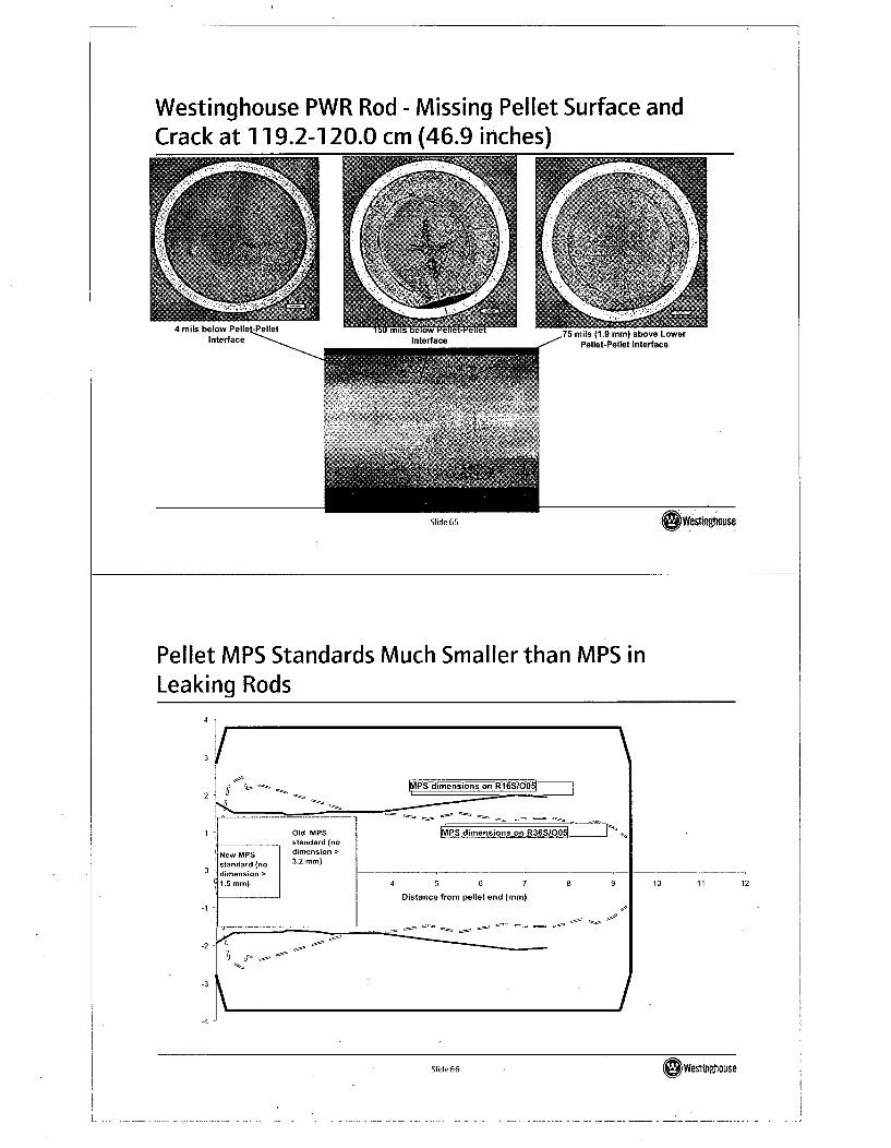
Westinghouse PWR Rod - Missing Pellet Surface andCrack at 119.2-120.0 cm (46.9 inches)
Interface
eWesfingtouseSlide 65
Pellet MPS Standards Much Smaller than MPS inLeaking Rods
10 11 12
-4
Slide 66 SeWesinvnouse
PCI Analysis Result Examplea, b,c
Slide 67 ý&Weslg Wmuse:
Integrated Pellet Quality Improvement Plana,c
Slide 68 ~~Westrngtlrnise
Slide 68OWevingrhouse
Summary & Conclusions
" Significant improvements in grid to rod fretting performance are beingrealized as new fretting resistant designs are replacing old products
* Debris induced leakers are being addressed by product improvements wherepossible and increased focus on FME control by sites as part of the "0 By 10"initiative
* New tools enable core designers to more accurately assess risk of crudformation in core loading pattern decision making process
* Major capital investments have been made and are underway to achieve thequality levels required to support leaker free fuel operation
Slide 69 OWesinghouse
Questions?
Slide 70 ~~~Westrnghouse
Slide 70 Wesiinghouse
Optima3
Westinghouse/NRC Fuel Update MeetingColumbia, SCFeb 20,2008
Slide 1 awwflinhouse
Presentation Overview
- SVEA-96 Optima2* Performance
- SVEA-96 Optima3* Key features and Components
* Verification
* Introduction
- Conclusions
Slide 2S2weslinnouse
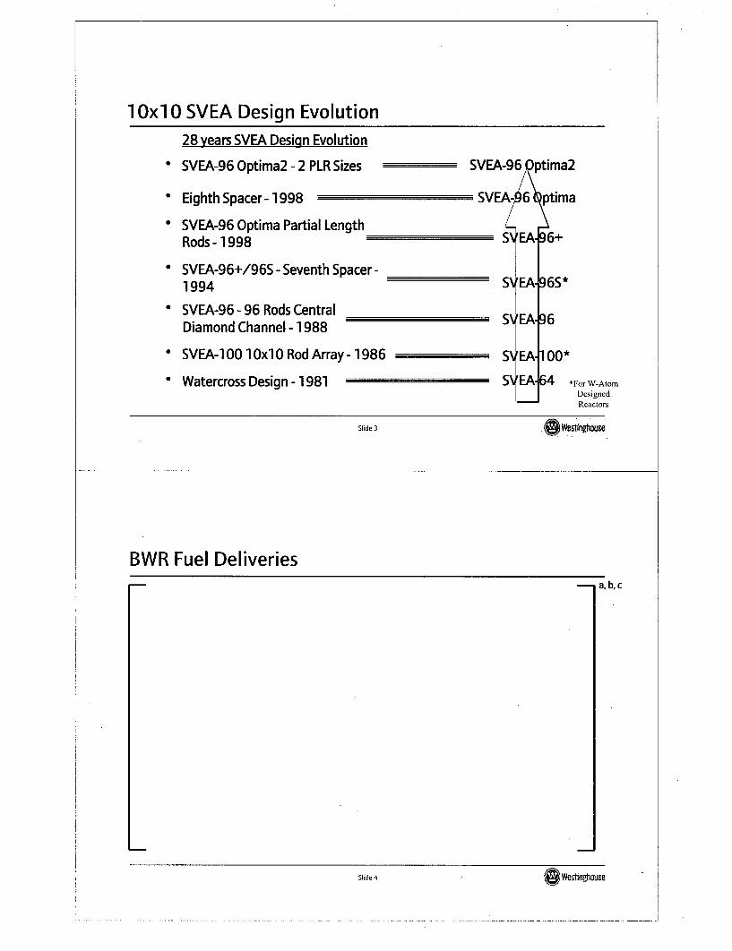
1 OxI 0 SVEA Design Evolution
28 years SVEA Design Evolution
0 SVEA-96 Optima2 - 2 PLR Sizes SVEA-96 Qptima2
* Eighth Spacer - 1998 SVI
* SVEA-96 Optima Partial LengthRods - 1998
* SVEA-96+/96S - Seventh Spacer -1994
* SVEA-96- 96 Rods CentralDiamond Channel - 1988
* SVEA-1 00 1 0xI 0 Rod Array - 1986
" Watercross Design - 1981
EAL-6 Q:ptima
SVEA496S*
SVEA196
S EA
SVEAI-
100*
64 *For W-AtormDesignedReactors
Slide 3 GWesfnghouse
BWR Fuel Deliveriesa,b,c
Slide 1 Weslngtwuse
Slide 4GWesling.house
BWR Fuel Burnup Experience, 2007a,b,c
Slide 5 (wesingtouse
SVEA-96 Optima2Deliveries
a, c
L
Slide 6 ()Wesilnghouse
Debris fretting mitigationDebris filter - TripleWave
a, b, c
Slide 7 Oweshngtoise
Implementation of TripleWavea, c
Slide 8 Slide 8 OWesinphnuse
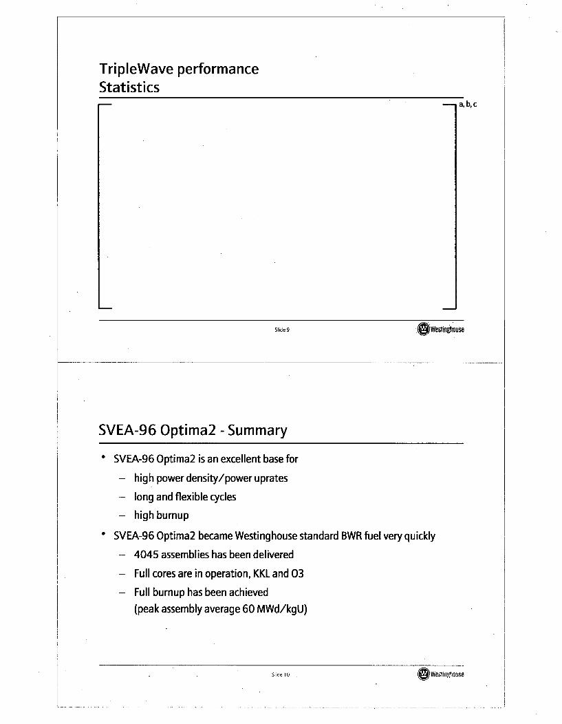
TripleWave performanceStatistics
a,b,c
Slide 9 ,(Dwesonognouse
SVEA-96 Optima2 - Summary
* SVEA-96 Optima2 is an excellent base for
- high power density/power uprates
- long and flexible cycles
- high burnup
* SVEA-96 Optima2 became Westinghouse standard BWR fuel very quickly
- 4045 assemblies has been delivered
- Full cores are in operation, KKL and 03
- Full burnup has been achieved
(peak assembly average 60 MWd/kgU)
Slide 10i 1Werngause
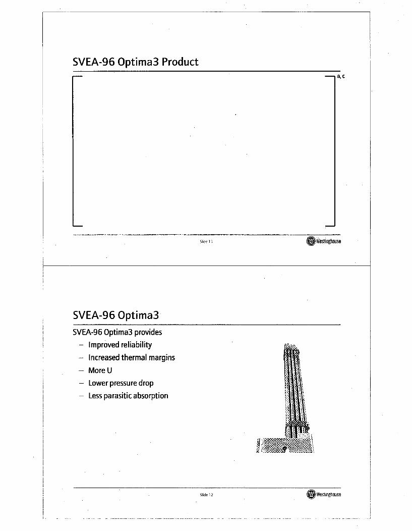
SVEA-96 Optima3 Producta, c
Slide 11 Wslingilouse
SVEA-96 Optima3SVEA-96 Optima3 provides
- Improved reliability
- Increased thermal margins
- More U
- Lower pressure drop
- Less parasitic absorption
Slide 12S( Wesinghause
SVEA-96 Optima3a, c
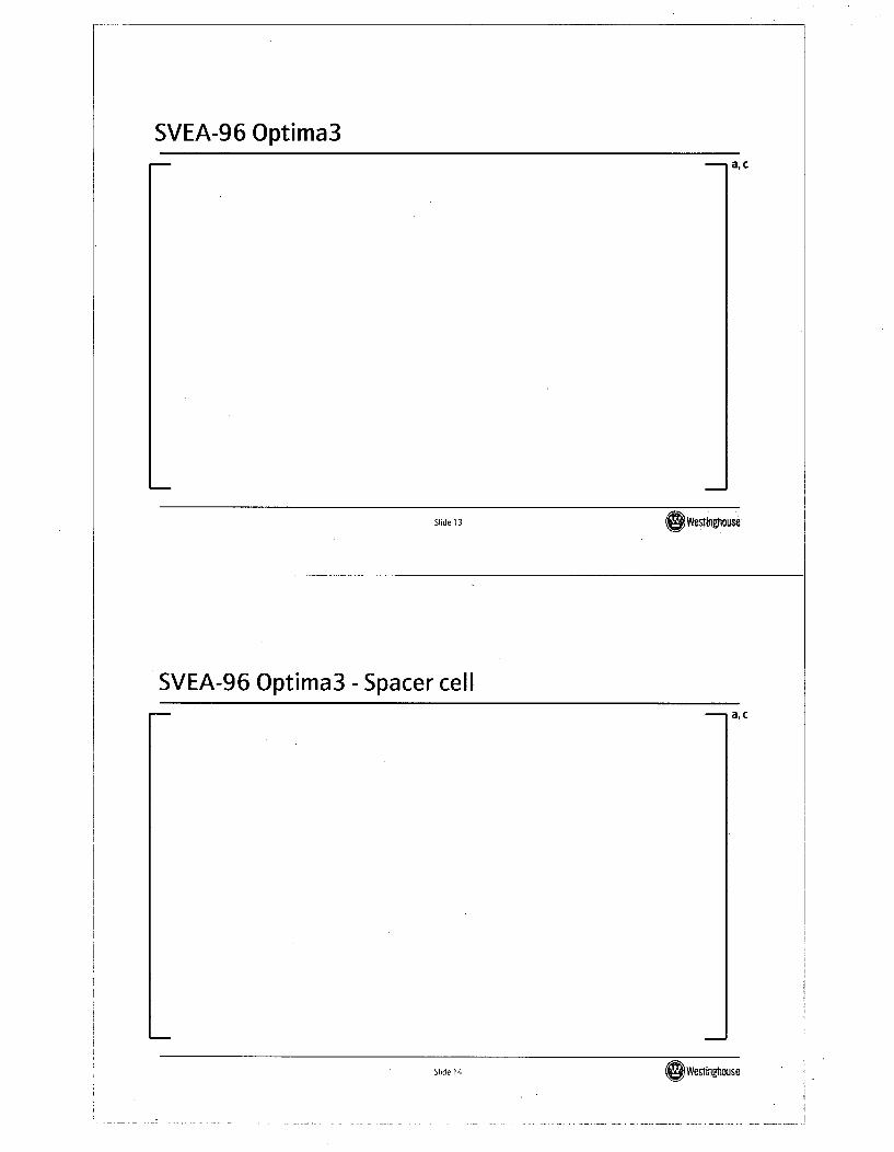
Slide 13 Oweslinghousi
SVEA-96 Optima3 - Spacer cella, c
Slide 14 Wes~tngtlouse
Slide 14 OWeslinghouse
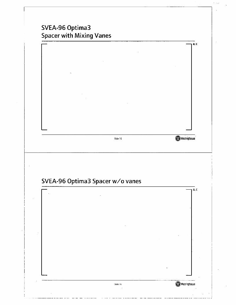
SVEA-96 Optima3Spacer with Mixing Vanes
a, c
Slide 15 A vim-tnfluS8
SVEA-96 Optima3 Spacer w/o vanesa, c
Slide 16SeWesliapause
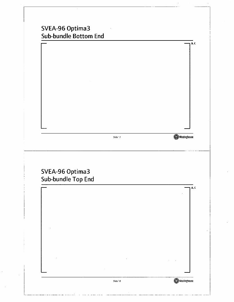
SVEA-96 Optima3Sub-bundle Bottom End
a, c
Slide 17 (swegin&M
SVEA-96 Optima3Sub-bundle Top End
a, c
Slide 18 Slide 18 O WesTingflouse
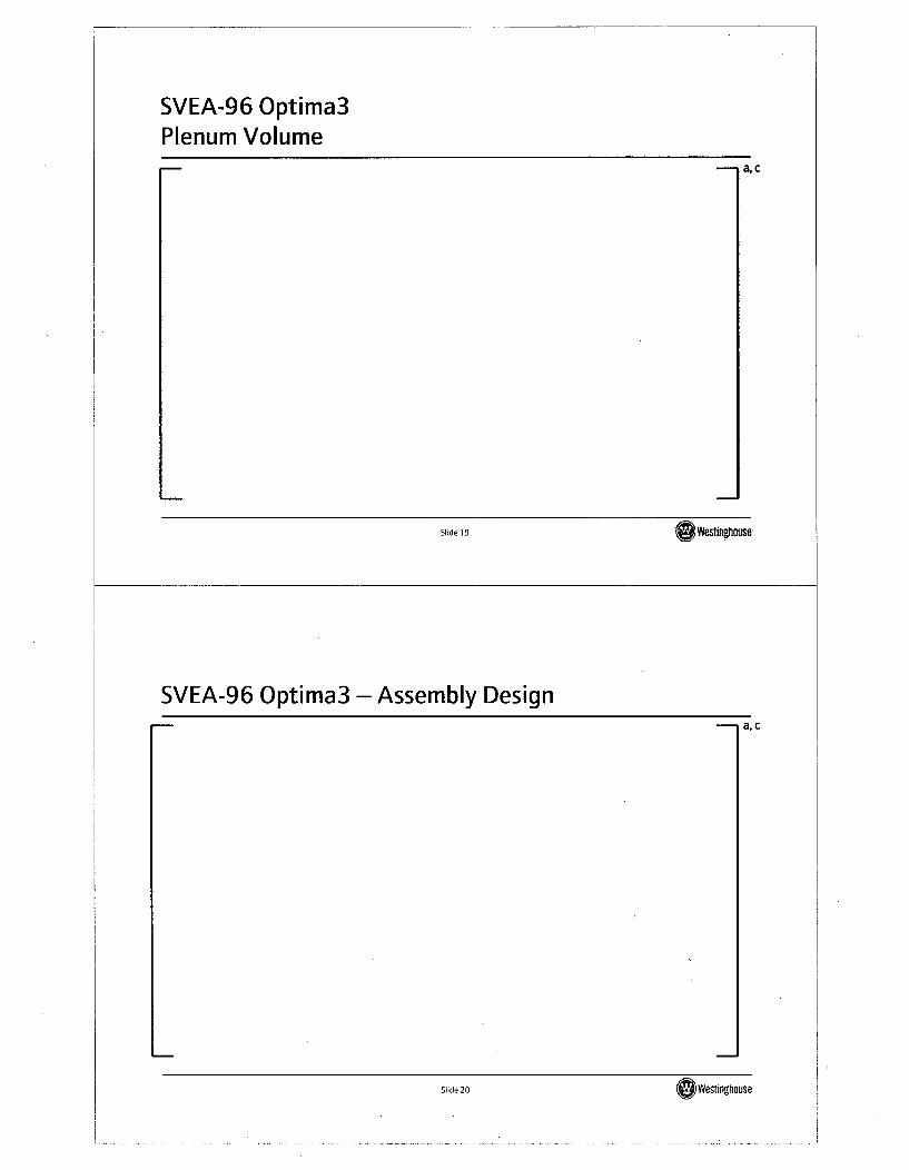
SVEA-96 Optima3Plenum Volume
a, c
Slide 19
SVEA-96 Optima3 - Assembly Designa, c
Slide 20d 2Westnghause
SVEA-96 Optima3Thermal Hydraulic Performance
a, c
Slide 21 OWMInghouse
SVEA-96 Optima3 - Verificationa, c
Slide 22 (OYwestinghouse
j
ADOPTAdvanced Doped Pellet Technology
a, b.c
Slide 23 (sWestinghouse
ADOPT - Objectives
1. Higher density
2. Reduced fission gas release-Demonstrated by two independent [ ]a,c tests-Gamma measurements in [ I ac
-On-line test in [ ] a, c /evaluation ongoing
3. Increased PCI threshold" Positive indications from a I I ac ramp test" Creep test at [ I a, c
4. Improved secondary degradation behaviorAutoclave corrosion testsS[1] a~c in-reactor washout test
Slide 24OWeOnghouse
Fission Gas Release -
Gamma Scan at [ I a,ca, b,c
Slide 25
ADOPT Verificationa, c
Slide 26dWeslinghouse
Debris Fretting Mitigation Improvementsa, c
Slide 27 (&Wesfinghouse
Debris fretting mitigationCatching tests with spacers
a, b,c
Slide 28d 2Weslinahouse
Debris fretting mitigationCombination of spacer and filter
a, b, c
Slide 29I Weftftghouse
ZIRLO for BWR Fuel Channelsa, c
Slide 30S 3Weslinghouse
SVEA-96 Optima3 - Summarya, c
Slide 31 OWeslinghouse
US Applicationsa, c
Slide 32 ~~~We~tfngtiouse
Slide 3200 WesfinZhouse
Conclusions- SVEA-96 Optima2 is a well proven design for US BWRs
- Further enhancements with SVEA-96 Optima3" An evolutionary design* Key proven components of SVEA-96 Optima2 maintained* All loop test completed successfully
- SVEA-96 Optima3 components in verification since 2003* Inspections 2004 and 2005 showed good behavior" Full burnup inspection in 2008 outage
- SVEA-96 Optima3 reload readiness from 2010* US introduction program to be decided
Slide 33 OWestingtiouse
Questions?
Slide 34 Westin~tiouse
Slide 34OWestinghouse
Spent Fuel Pool Criticality Safety
Westinghouse/NRC Fuel Update MeetingColumbia, SCFeb 20,2008
Slide 1 G~Wesfnghouse
Spent Fuel Pool CriticalityPast Submittals
* [* [* [* [* [* [
]ac 12/2000, ML003761578
]axc 9/2002, ML022610080
]a.c 04/2003, ML030910485
]a.c 09/2005, ML0524201 10
]a,c 09/2005, ML052420110
]axc 02/2006, ML060250208
Slide 2 SWesingtouse
Spent Fuel Pool CriticalityCurrent and Future Efforts
axc
laxc directed to withdraw - will be resubmitted in the near future
* [ lac directed to withdraw and fix-will be resubmitted in thenear future
* [ ]a,c directed to separate from uprate package or delay the uprate
(chose to separate and pursue in parallel to the uprate licensing)* [ ]ac awaiting review
1 [ Jac will be submitted in 2nd Qtr'08.
* The analyses to be submitted or resubmitted will incorporate additions based on the []a-c experience
Slide 3 ~~~Westingtiouse
Slide 3 (OWestinghouse
High Burnup and New Alloy Strategies
Westinghouse/NRC Fuel Update MeetingColumbia SC
February 20,2008
Slide I (SWestlngtrnuse
Strategy
Alloys:
-Past Zr-4
- Current: ZIRLOTM
- Near-term future: Optimized ZIRLO'T
- Future: AXIOM'T and advanced alloys-Ia, c
Slide 2 Sd2Wesingihouse
Subject Areas
* LTA Programs
* High-Temperature Oxidation Tests
* Optimized ZIRLOTh'
* AXIOM'T 1
" Status of [ ]axc Creep & Growth Specimens
* High Burnup Data Needs
Slide 3 ( )weslingouse
LTA Programs
Slide 4 Slide4 (~eftinghouse
Westinghouse High Burnup ZIRLOT LTA Summarya, b,c
Slide 5 Owestinguse
STD ZIRLO TM (SRA) Hotcell Examsa, b, c
Slide 6 Si weinhouse
Summary of LTA Programsa,b,c
Slide 7 I Westinoiouse
Breakaway Oxidation Tests
Slide 8 S )Westingnause
--I
Breakaway Oxidation
" Defined as long-term exposure to medium LOCA temperatures such as occursin a Small Break LOCA
* Temperature range of interest 650 to 1000 °C
• Concern raised due to El 10 experience
- Clarify requirements for "advanced alloy" evaluations
Slide 9 (S Wesfi•ngouse
Breakaway oxidation tests
* ANL results showed breakaway oxidation was alloy-dependent
- Break away defined as [H] level of 200 ppm
- Time required to get to 200 ppm H varies by temperature; generally,increasing temperature decreases time required to achieve 200 ppm
* Westinghouse testing has shown:
- Similar results to ANL for as-received ZIRLO' cladding
- Virtually identical performance for Zirc-4 and ZIRLO"
- Thin oxide film equivalent to reactor heating up significantly increasesbreakaway time
- Opt ZIRLOT ' has longer breakaway time than ZIRLOiN
Slide 10 ( Weslnghouse
Background
• Oxidation tests performed at 970 TC in a flowing steam environment for 3000-5400 seconds
• ZIRLOT', Optimized ZIRLOiN and Zircaloy-4 claddings tested
" ZIRLO'" tested in both the as-received and pre-filmed condition
* ZIRLOiN tested with and without scratches
* STC facility also conducted long term oxidation testing ZIRLOTh and Zircaloy-4claddings over a temperature range from 950 0Cto 1020 °C (90-minute hold)to determine a minimum time to breakaway oxidation.
Slide 11 owestingtiouse
Results - Columbia Testinga, b,c
Slide 12 (~ efslinghouse
I
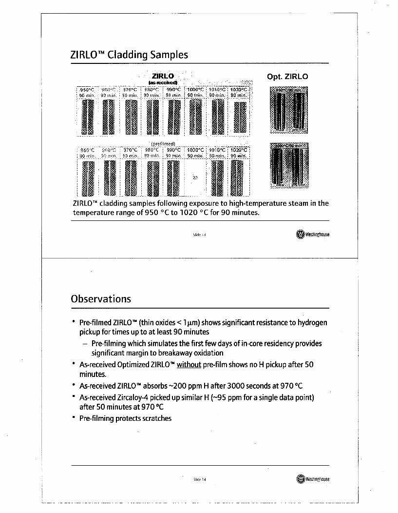
ZIRLO TM Cladding Samples
ZIRLO.
98 mo 8O min, 90 rminý min- 90 mim 90fmit,.11111Opt. ZIRLO
8 ri 0 mir •0 n mn. 80 mia 90m~m : 90mn,9mm 90m~m 90mrm.
11 0 C i 2 i
ZIRLO TM cladding samples following exposure to high-temperature steam in thetemperature range of 950 °C to 1020 'C for 90 minutes.
Slide 13
Observations
* Pre-filmed ZIRLO"' (thin oxides < 1 lam) shows significant resistance to hydrogenpickup for times up to at least 90 minutes
- Pre-filming which simulates the first few days of in-core residency providessignificant margin to breakaway oxidation
* As-received Optimized ZIRLO' without pre-film shows no H pickup after 50minutes.
* As-received ZIRLO' absorbs -200 ppm H after 3000 seconds at 970 °C
* As-received Zircaloy-4 picked up similar H (-95 ppm for a single data point)after 50 minutes at 970 °C
* Pre-filming protects scratches
Slide 14 W'esimroghause
j
Breakaway Testing at STC
" Most of the ZIRLOt" samples exhibited black adherent oxide over the entiresample.
* Tan oxide (when present) was associated with the ends of the samples and isnot interpreted as the onset of breakaway oxidation. The tan oxide formed atthe geometrical discontinuity of the cut end.
* Pre-filmed ZIRLO"A samples (360 °C/72 hours) exhibited less tan oxide at theends but were not immune from formation of tan oxide
* Optimized ZIRLOTM behaved better
Slide 15 (eWeslgh~ause
Breakaway Testing at STC (Cont'd)
" The Zircaloy-4 samples exhibited significantly higher weight gains than ZIRLOat temperatures above 980 °C
* Zircaloy-4 samples were more prone to forming a gray (non-protective) oxidethan ZIRLOT were to forming a tan (non-protective) oxide
* The temperature/time associated with the largest amount of tan/gray oxidewas 1000 °C/90 minutes suggesting that this temperature/time combinationwould be associated with a minimum time to breakaway oxidation.
Slide 16le Wevinghouse
Breakaway Oxidation Tests - Summary
* Westinghouse believes that breakaway test results are highly dependent on testsetup and not representative of in-core performance
* Test results should be able to be replicated
* Rulemaking needs to allow for completion of testing and reporting of results-current RES interpretation of ANL data is overly restrictive and notphenomenologically related to reactor operating conditions.
Slide 17 OWeweongbuse.
Optimized ZIRLO'
Slide 18 S 1westingtouse
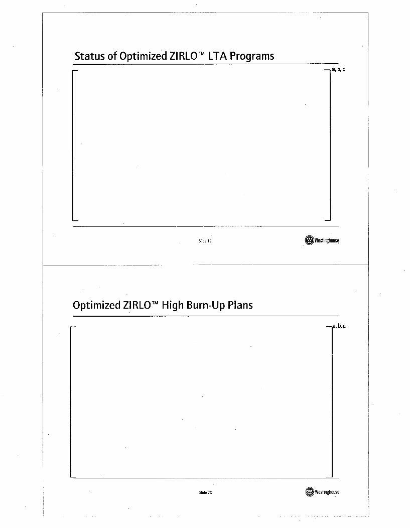
Status of Optimized ZIRLO TM LTA Programsa, b,c
Slide 19 (Swesinghouse
Optimized ZIRLO TM High Burn-Up Plans
a. b.c
Slide 20S2Weoffghouse
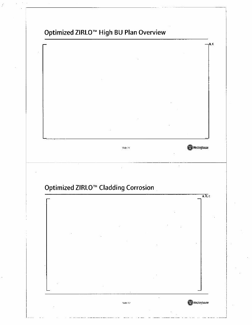
Optimized ZIRLOTM High BU Plan Overview
.,a, C
Slide 21 (swesflnghouse
Optimized ZIRLOTM Cladding Corrosiona,b,c
Slide 22S Wed2tnghouse
Results of Optimized ZIRLO TMPIEs
-, a, c
Slide 23 Weftlngtruse
Summary of Current Optimized ZIRLO TM Performance
" Optimized ZIRLO cladding has experience in 13 reactors
" Optimized ZIRLO cladding normally will have a PRXA structure with thermal
creep rates equivalent to standard ZI RLO
" Creep is within current model bounds
" Corrosion results indicate significant corrosion improvements (> 30%
reductions)
" Fuel rod growth is equivalent to standard ZIRLO
* First commercial batches in 2008
Slide 24Sd Wegfinq ouse
AXIOMTM
Slide 25 (owesionouse
AXIOMTM LTAsr-, I:,c
Slide 26 S 2Wevinghouse
Nominal Alloy Compositions for the AXIOMTM Alloys
a, b,
Slide 27 G ~Westingtouse
AXIOMTM Corrosion Performance,a, C
Sfide 28 S~d002 Wemlinghouse
Current AXIOMTM LTA Plans,a, b, c
Slide29 OWestifocuse
Unfueled Cladding Creep and Growth Tests
Slide 30S0 Weslingrhouse
Status of [ ]a,c Creep and Growth Specimensa, b.c
Slide 31 OWestinghause
Status of [ ]a,c Creep and Growth Specimens-n a, c
Slide 32Sewesinqhouse
Irradiation Schedulea, c
Slide 33 )westing use
What Has Been Learneda, c
. Slide 34 SeWestinghouse
[ ] a, c
a, b,c
Slide35 (O)Westinughouse
[] a, c
a,b,c
*1-
Slide 36 Shde 3 Westinghouse
a,c
a, b,c
Slide37 (o'wesfinghouse
High Burnup Data Needsa, c
Slide 38 Slide38 o weslingflouse
CE 1 6x1 6 NGF Update
Westinghouse/NRC Fuel Update MeetingColumbia, SCFeb 20, 2008
Slide 1 Weswinghause
Outline" NGF Region Implementation in [
• NGF Region Implementation in [
I a, c
a, c
Slide 2 Slide 2 Westinghlouse
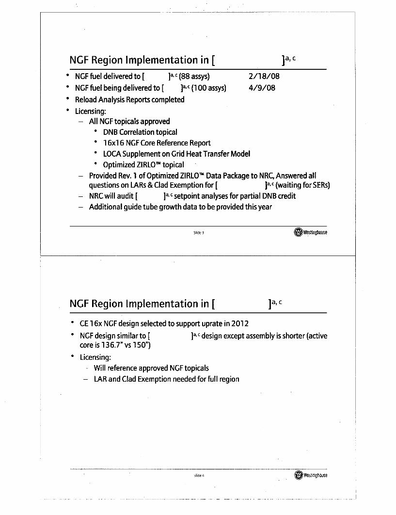
NGF Region Implementation in [ I a, c
* NGF fuel delivered to [ a, c (88 assys) 2/18/08" NGF fuel being delivered to [ ]a.c (100 assys) 4/9/08* Reload Analysis Reports completed* Licensing:
- All NGF topicals approved* DNB Correlation topical" 1 6xi 6 NGF Core Reference Report* LOCA Supplement on Grid Heat Transfer Model
* Optimized ZIRLO' topical- Provided Rev. 1 of Optimized ZIRLOT Data Package to NRC, Answered all
questions on LARs & Clad Exemption for [ ]a,c (waiting for SERs)- NRC will audit [ ]a.c setpoint analyses for partial DNB credit- Additional guide tube growth data to be provided this year
Slide 3 swestin.4ouse
NGF Region Implementation in [ Ia, c
* CE 1 6x NGF design selected to support uprate in 2012
* NGF design similar to [ ]a,c design except assembly is shorter (activecore is 136.7" vs 150")
* Licensing:- Will reference approved NGF topicals
- LAR and Clad Exemption needed for full region
Slide 4S4Welintrhouse
New ZIRLOTM Corrosion Model
Westinghouse/NRC Fuel Update MeetingColumbia, SCFeb 20, 2008
Slide 1 .GWestinghouse
Outline" Background
* Status on New ZIRLOTM Corrosion Model
* Topical Preparation" Timeline
* Eliminate FDI Restriction for ZIRLOTM in CE NSSS Plants
Slide 2 SeWeminghouse
Background" Westinghouse has accumulated a significant amount of ZIRLO-d and Optimized
ZIRLO' data
- More than 50,000 data points
* The current corrosion model is being updated to use all available data to makecorrosion predictions in reload design analyses
Slide 3 ,ewestingtiuse
Westinghouse ZIRLO TM Database
a, b,c
Slide 4 ~~~Westing~ouse
Slide 400 Wesfinghouse
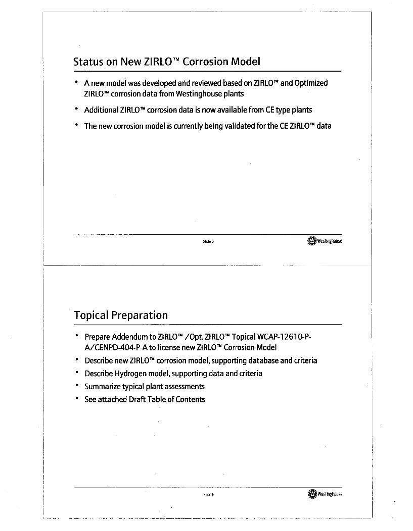
Status on New ZIRLOTM Corrosion Model
" A new model was developed and reviewed based on ZIRLO" and OptimizedZIRLOJN corrosion data from Westinghouse plants
* Additional ZIRLO Im corrosion data is now available from CE type plants
" The new corrosion model is currently being validated for the CE ZIRLO Im data
Slide 5 (OWesin~huse
Topical Preparation
Prepare Addendum to ZIRLOI /Opt. ZIRLOI" Topical WCAP-1 261 O-P-A/CENPD-404-P-A to license new ZIRLOTm Corrosion Model
* Describe new ZIRLOT' corrosion model, supporting database and criteria
* Describe Hydrogen model, supporting data and criteria
* Summarize typical plant assessments
* See attached Draft Table of Contents
Slide 6 Slide 6 o wevTinghouse
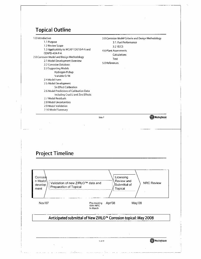
Topical Outline
1.0 Introduction1.1 Purpose
1.2 Review Scope
1.3 Applicability to WCAP-1 261 0-P-A and
CEN PD-404-P-A2.0 Corrosion Model and Design Methodology
2.1 Model Development Overview
2.2 Corrosion Database
2.3 Supporting Models
Hydrogen Pickup
Variable O/M
2.4 Model Form
2.5 Model DevelopmentI Sn Effect Calibration
2.6 Model Predictions of Calibration Data
Including Crud Li and Zinc Effects
2.7 Model Residuals
2.8 Model Uncertainties
2.9 Model Validation
2.10 Model Summary
3.0 Corrosion Model Criteria and Design Methodology
3.1. Fuel Performance3.2 ECCS
4.0 Plant AssessmentsCalculations
Text5.0 References
Slide 7 OWestiflghouse
Project Timeline
Corrosi Licensingn Model\ -. ---- ]\Review and___ndeveloo Validation of new ZIRLO TM data and Review and
ment ~ -___.Topicam n / I .P r e p a r a t io n o f T o p ic a l T o cal_ "
Nov'07 Pre-meeting Apr'08 May'08With NRCIn March
Anticipated submittal of New ZI RLO h Corrosion topical: May 2008
SIi~1~ ~ ~~~We~tInghause
£1idA R0 Weslinghouse
Eliminate FDI Restriction for ZIRLO TM in CE NSSS Plants
* A Fuel Duty Index (FDI) restriction was imposed by NRC to licensees forimplementing ZIRLOTM cladding in CE plants since no ZIRLOT ' corrosion data wasavailable in CE plants
* This restriction can be eliminated after enough ZIRLOTM data is accumulated fromCE plants (1 4x and 1 6x) and corrosion behavior of the data is similar toWestinghouse ZIRLO TM database
* A generic letterwill be prepared for licensees to submit to NRC
Slide 9 OWestinghouse
Foxfire
Westinghouse/NRC Fuel Update MeetingColumbia, SCFeb 20, 2008
Slide 1 (OWeslinghouse
What is Foxfire?--- a, c
Slide 2 Slide 2 IQ Westqrnhouse
What is Foxfire?a, c
Slide 3 (Westingtiouse
Key Model Upgrade/Addition Relative to PADa, c
Slide 4ieWesilnghouse
Key Model Upgrade/Addition Relative to PADa, c
Slide 5 (Owes~tlnghuse
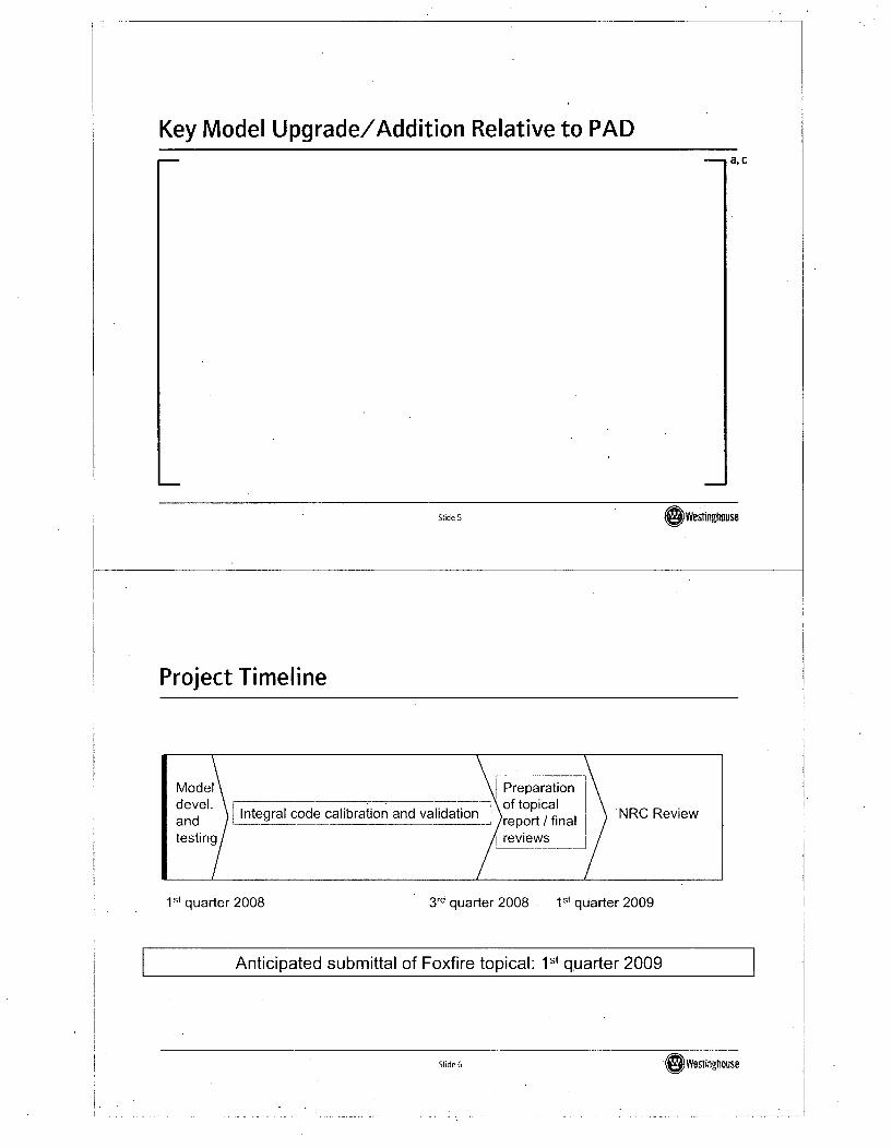
Project Timeline
Model n___Preparationadevel. \of topical
Integral code calibration and validation NRC Reviewand ---__ report / final NCRvetesting reviews
1st quarter 2008 3rd quarter 2008 - 1st quarter 2009
Anticipated submittal of Foxfire topical: 1st quarter 2009
Slide 6 (Owestingrhouse
APIO00 Fuel Update
Westinghouse/NRC Fuel Update MeetingColumbia, SCFeb 20, 2008
Slide 1 OWestinghouse
Agenda
* Westinghouse Fuels approach to initial core load for APi 000
* The Core Reference Report
* Overview of other Fuel and Core Components
* Gray Rod Enhancement (GRCA)
Slide 2S 2Weslinghouse
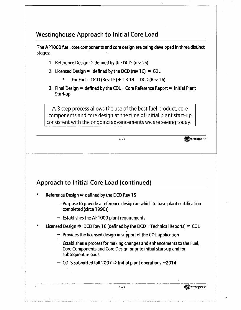
Westinghouse Approach to Initial Core Load
The AP1 000 fuel, core components and core design are being developed in three distinctstages:
1. Reference Design * defined bythe DCD (rev 15)
2. Licensed Design 4, defined by the DCD (rev 16) r* COL
For Fuels: DCD (Rev 15) + TR 18 = DCD (Rev 16)
3. Final Design -> defined by the COL+ Core Reference Report r* Initial PlantStart-up
A 3 step process allows the use of the best fuel product, corecomponents and core design at the time of initial plant start-up
consistent with the ongoing advancements we are seeing today.
Slide 3 Westinghouse
Approach to Initial Core Load (continued)
Reference Design * defined by the DCD Rev 15
- Purpose to provide a reference design on which to base plant certificationcompleted (circa 1990s)
- Establishes the AP1 000 plant requirements
Licensed Design '* DCD Rev 16 [defined by the DCD + Technical Reports] '* COL
- Provides the licensed design in support of the COL application
- Establishes a process for making changes and enhancements to the Fuel,Core Components and Core Design prior to initial start-up and forsubsequent reloads
- COL's submitted fall 2007 r* Initial plant operations -2014
Slide 4 00Wesfinghouse
Approach to Initial Core Load (continued)
* Final Design r* COL + Core Reference Report
- Submitted after the initial COL is issued but prior to initial fuel load withsufficient time for NRC review and approval.
- A core reference report submitted to the NRC for review and approval(consistent with the requirements to address Tier 2* items)* Addresses enhancements to fuel assembly and core components
design
" Addresses initial fuel loading pattern, control rod designations andassociated core physics parameters
Standardized Core Reference Report for the API 000 fleet would beincorporated into the New Plant License following the standard licenseamendment process (10 CFR50.92)
- Provides for NRC review & approval of initial core
Slide 5 (O Wesringhrouse
The APO00 Core Reference Report
AP1 000 Core Reference Report
0 The API 000 Core Reference Report once reviewed and approved by the NRCwould address any final changes to the fuel assembly design, methods andrequirements prior to initial core load.
* The report presents the COL holder's actual initial core (cycle 1) fuel loadingpattern, control rod designation (both RCCAs and GRCA) and associated corephysics parameters at the time of initial start-up.
Slide 6 )Wevingfouse
Core Reference Report
Examples of Fuel and Core Design evolutions that will be addressed in the CoreReference Report:
a, c
Core Reference Report will be submitted to the NRC for review andapproval and there will be no change to the Chapter 1 5 conclusions.
Slide 7 G~WO I ingthouse.
Approach to Initial Core Load
* Basic Ground Rules for the Initial Core
Tier 2 * changes must be NRC Reviewed and Approved
"DCD Design Criteria" is defined as the Principal Design Requirements
" Section 4.1.1 defines the Principal Design Requirements
" Conclusions of the Chapter 15 Safety Analyses remain valid
Actual fuel and core component designs (including RCCAs and GRCAs),loading pattern, control rod designations and core physics changes fromthe design in the DCD will be submitted to the NRC for review and approval(Core Reference Report) prior to initial fuel load.
Slide 8 Sli. (O Weslingt~oute
Next step for Initial Core Load
AP1 000 Core Reference Report
* Reviewed and approved by the NRC via LAR process
* Addresses final changes to the methods, core, fuel and core componentsdesign prior to initial core load
Core Reference Report to be submitted to the NRC consistent with constructionschedule to maximize opportunity to incorporate fuel and core design evolutions.
* Allow sufficient time for NRC review
• Follow Topical/LAR Process
Slide 9 OWesgtigouse
Status of Fuel Licensing Activities
* Technical Report (TR-1 8) submitted Oct 31,2006
- COL Information Item Addressed
- Limited design changes to reflect enhancements or address inconsistencies
- Provided the basis for the changes in DCD Rev .16 currently under review
* Responded to all RAIs by Sept 30, 2007
Slide 10 Westinghouse
Slide 10(OWevinghouse
Overview of other Fuel Assembly and Core Components* Fuel Assembly
- Base design is Westinghouse Robust Fuel Assembly (RFA)
- 14 foot active fuel length (South Texas, EDF, and Doel 4 use the 14', RFA design)
- Features adapted to API 000 requirements (i.e., Top Mounted Instrumentation)
* Core Components
- Core components are based on standard designs
-GRCAs have been adapted from RCCAs to enable utilization of MSHIM controlstrategy
-Core components and top nozzle have been adapted to allow top mounted in-coreinstrumentation
Slide 11 .@ Westinghouse
API 000 Fuel Design Based on RFA
* AP1 000 basic fuel assembly design is derived from the Westinghouse 1 7X1 7Robust Fuel Assembly (RFA) XL design
a Westinghouse has significant experience with the RFA design
Detailed AP1 000 fuel dimensions defined to meet specific API 000 designrequirements
Slide 12 (S Westinghouse
API 000 Fuel Features-- a, c
Slide 13 (Gwestinghouse
GRCA use in MSHIM Operation
SAPM 000 uses MSHIM control strategy for reactivity changes associated with powerlevel, power distribution and temperature control.
SMSHIM operation allows significant simplification in CVCS by eliminating previousrequirements for boron change associated with power change.
* Operational boron change requirements with MSHIM are limited to startup, shutdownand fuel depletion.
SMSHIM control strategy fully automated in API 000 power control system at powerlevels [ ]a,c
Slide 14 ~~~We~tingtrnuse
Slide 14 GlWeslinghouse.
Controls Rods (RCCAs) are different from Gray Rods (GRCA)a, c
Slide 15 O~Westinghouse
GRCA Design Evolution- a,c
Slide 16 S 6Westinghouse
Advanced GRCA Designa, c
Slide 17 ~~Westinghmose
[ I a,c
1 ac
Slide 18 Slide18 ~owesfingtrnuse
Summary
* API 000 Core Reference Report
- Reviewed and approved by the NRC via LAR process
- Addresses final changes to the methods, core, fuel and core components designprior to initial core load
* DCD 12 is the current GRCA Design
- Westinghouse is developing an advanced GRCA design utilizing [ ]ac asa gray material
- NRCs timely review and approval of the Enhanced GRCA Rodlet Design Topicalneeded for the introduction of this enhanced GRCA rodlet into the initialcore for AP 000
Slide 19 (Owesrngoouse
Questions?
Slide 20 Slide 20 (Westingt~ouse
Overview of BEACON TM Sentinel TM
(BEACON TM Fixed Incore Protection System)
Westinghouse/NRC Fuel Update MeetingColumbia, SCFeb 20, 2008
Slide 1 0 Westinghouse
BEACON TM Sentinel TM OutlineS
S
0
0
0
0
New innovative WEC technology for FutureBackgroundCPCS"` OverviewBEACON"' Sentinel' SummaryInnovative BEACON" Sentinel' ConceptsQuestions and Comments?
Slide 2 S 2Westinghouse
New innovative WEC technology for Future
* Purpose- Make Safety Decisions based upon better knowledge
- Use Incore informationPresent* Conservative using ex-core data and offline radial peaking factors
- Future0 More accurate (3-D information) using information from inside reactor
• Goals- State of the Art Protection System applicable to all PWRs- Improved accuracy can provide support
0 for power uprates,* capacity factor improvements* other operational benefits
* - Improved Algorithms simplify analysis requirements
Slide 3 S WesfingthousJe
Background* Core Protection Calculator System (CPCS')
- Most advanced operating PWR protection system in the world- Developed in 1970s to work on 1970s era computer hardware- Currently operating at 7 plants in US and 8 plants in Korea- No significant functional design improvements since 1986- Several plants operating with recent upgrade to "Common Q" hardware
with essentially same functional design* Current System Detector Information
- Protection System uses Excore Information- Monitoring System uses Incore Information
Slide 4 O Weslina0ouse
Background - cont'd
" BEACON"'- State of the Art Monitoring System for PWRs- Licensed and Marketed to all PWRs
• COLSS"'- Digital on-line monitoring system used at plants with CPCSm
• BEACON- COLSS"'- Licensed state-of-the-art monitoring system that combines the best
modules of BEACON"' and COIS"'* Basis for BEACON"' -Sentinel"
- Builds on advanced concepts - CPCS'm, BEACON"' and BEACON-COLSS"- Better computer hardware/software technology today- Advanced nuclear design tool
Slide 5 e•Westnfihouse
CPCSTM OverviewS4 channel system
- 2 channels to trip with 1 channel allowed to be in bypass* Each channel calculates reactor power & axial power shape
- based on input from single 3-level excore detector* Each channel calculates radial peaking factor
- based on pre-calculated look-up table and target rod positions* On-line DNBR calculation* Uncertainty analysis conservatively compensates for power distribution & TH
algorithm simplifications
Slide 6 ( WatlinfhOUSe
BEACONTM - SentinelTM Overview
* Same 4 channel system as CPCS"° Same protection functions &transient response as CPCS"* Being developed to work on modern computer hardware with modern software
technology* Applies BEACON-COLSS'T concepts to safety grade protection system* Uses Incore Information for Protection System
Slide 7 Wemsti*Dhuse
Innovative BEACON TM SentinelT M Conceptsa, c
Slide 8 Slide 8 weslinghouse
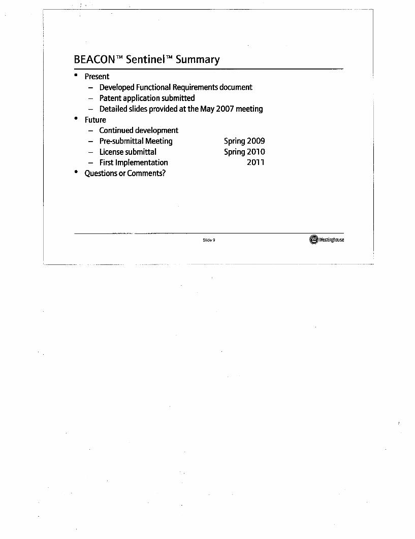
BEACONTM SentinelTM Summary
* Present- Developed Functional Requirements document- Patent application submitted- Detailed slides provided at the May 2007 meeting
* Future- Continued development- Pre-submittal Meeting- License submittal- First Implementation
• Questions or Comments?
Spring 2009Spring 2010
2011
Slide 9 (DWesting•ouse
Westinghouse Organization
Westinghouse/NRC Fuel Update MeetingColumbia, SCFeb 21, 2008
Slide 1 Westinghouse
Slide 1 :16w6stinghbus'e,
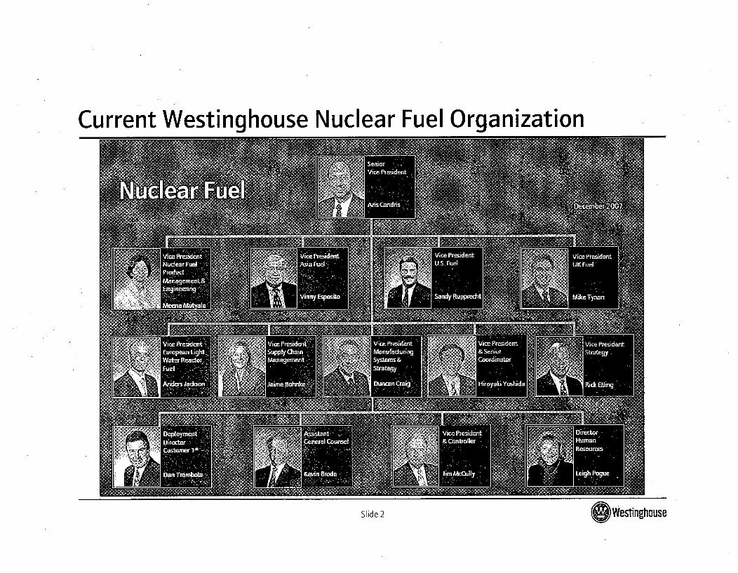
Current Westinghouse Nuclear Fuel Organization
Slide2 ld2Westinghouse
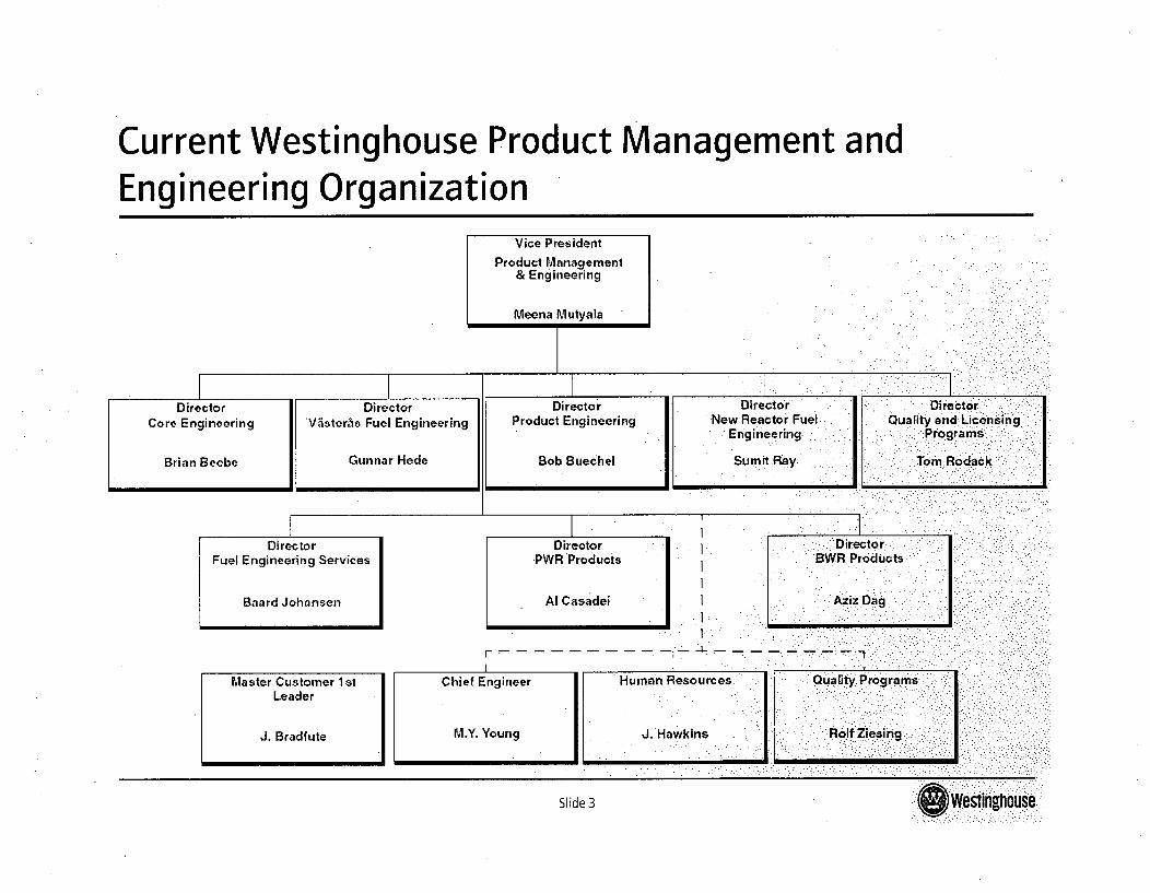
Current Westinghouse Product Management andEngineering Organization
Vice President
Product Management& Engineering
Meena Mutyala
Director Di rectorTDirector
DirectorCore Engineering
Brian Beebe
DirectorV~steris Fuel Engineering
Gunnar Hede
I
DirectorProduct Engineering
Bob Buechel
DirectorNew Reactor Fuel
Engineering...
Sum it Ray
DirectorQuality and Licensing
Tom Rodack
Director Director
DirectorFuel Engineering Services
Baard Johansen
Director
PWR Products
Al Casadei
1*.
1*
ý:.I Directo rBWR Products
Aziz Dag
r- - - - - - - - - - -I1
Master Customer 1stLeader
J. Bradfute
Chief Engineer Human Resources
M.Y, Young J. Hawkins
Quality Programs
Rolf Ziosing jSlide 3 Slide 3Westinghouse
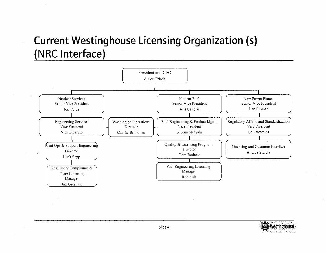
Current Westinghouse Licensing Organization(NRC Interface)
(s)
New Power PlantsSenior Vice President
Dan Lipman
Washington OperationsDirector
Charlie Brinkman
Slide 4 Westinghouse
Slide4 S West' Inghouse
Current Programs
Westinghouse/NRC Fuel Update MeetingColumbia, SCFeb 21, 2008
Slide I l Westrngtrnu Se
Current Programs
* Foxfire* 17x17 NGF
* Optima3
* High Burnup
* Axiom
" AP1000
* Spent Fuel Pool Criticality
Slide 2 li2Wesinghouse
Topical Report Schedules
Westinghouse/NRC Fuel Update MeetingColumbia, SCFeb 21, 2008
Slide 1 Slide 1O Westinghouse
PWR & API 000 Topical Report Schedulesa, c
Slide 2 Slide 2 stinghouse
BWR Topical Report Schedulesa, c
Slide 3 ldQ Wieinghouse
General Licensing Topics
Westinghouse/NRC Fuel Update MeetingColumbia, SCFeb 21,2008
Slide I O~Westinghouse
Agenda
* Interpretation of 10 CFR 50.59
* Reviewer Qualification and Training
* Integrated Reviews
* The Role of Metrics at the NRC
* The Role of Precedents
* Level of Detail Required to Support Reviews
* LTA Testing Program
* API 000 Fuel Licensing Process
Slide 2 Slide2 (~eftlnghouse
L. ..........