Embed Size (px)
Citation preview

Oracle® Communications Network Charging and Control
Advanced Control Services Technical Guide
Release 5.0.1
June 2013

ii NCC Advanced Control Services Technical Guide
Copyright
Copyright © 2013, Oracle and/or its affiliates. All rights reserved.
This software and related documentation are provided under a license agreement containing restrictions on use and disclosure and are protected by intellectual property laws. Except as expressly permitted in your license agreement or allowed by law, you may not use, copy, reproduce, translate, broadcast, modify, license, transmit, distribute, exhibit, perform, publish, or display any part, in any form, or by any means. Reverse engineering, disassembly, or decompilation of this software, unless required by law for interoperability, is prohibited.
The information contained herein is subject to change without notice and is not warranted to be error-free. If you find any errors, please report them to us in writing.
If this is software or related documentation that is delivered to the U.S. Government or anyone licensing it on behalf of the U.S. Government, the following notice is applicable:
U.S. GOVERNMENT END USERS: Oracle programs, including any operating system, integrated software, any programs installed on the hardware, and/or documentation, delivered to U.S. Government end users are "commercial computer software" pursuant to the applicable Federal Acquisition Regulation and agency-specific supplemental regulations. As such, use, duplication, disclosure, modification, and adaptation of the programs, including any operating system, integrated software, any programs installed on the hardware, and/or documentation, shall be subject to license terms and license restrictions applicable to the programs. No other rights are granted to the U.S. Government.
This software or hardware is developed for general use in a variety of information management applications. It is not developed or intended for use in any inherently dangerous applications, including applications that may create a risk of personal injury. If you use this software or hardware in dangerous applications, then you shall be responsible to take all appropriate fail-safe, backup, redundancy, and other measures to ensure its safe use. Oracle Corporation and its affiliates disclaim any liability for any damages caused by use of this software or hardware in dangerous applications.
Oracle and Java are registered trademarks of Oracle and/or its affiliates. Other names may be trademarks of their respective owners.
Intel and Intel Xeon are trademarks or registered trademarks of Intel Corporation. All SPARC trademarks are used under license and are trademarks or registered trademarks of SPARC International, Inc. AMD, Opteron, the AMD logo, and the AMD Opteron logo are trademarks or registered trademarks of Advanced Micro Devices. UNIX is a registered trademark of The Open Group.
This software or hardware and documentation may provide access to or information on content, products, and services from third parties. Oracle Corporation and its affiliates are not responsible for and expressly disclaim all warranties of any kind with respect to third-party content, products, and services. Oracle Corporation and its affiliates will not be responsible for any loss, costs, or damages incurred due to your access to or use of third-party content, products, or services.
iii
Contents
About This Document ................................................................................................................ vii Document Conventions ............................................................................................................ viii
Chapter 1
System Overview .................................................................................. 1
Overview ...................................................................................................................................... 1 What is the Advanced Control Services? .................................................................................... 1 What are the Main Components of ACS? ................................................................................... 3 What are the Functions of ACS? ................................................................................................. 7 ACS CDR/EDR ............................................................................................................................ 7
Chapter 2
Security Overview ................................................................................. 9
Overview ...................................................................................................................................... 9 Security in ACS ........................................................................................................................... 9 Defining the Security Levels ......................................................................................................10 Setting up ACS Security through SMS ......................................................................................12 Setting up ACS Security without using SMS .............................................................................16
Chapter 3
Configuring the Environment ............................................................. 19
Overview ....................................................................................................................................19 Configuring the Environment .....................................................................................................19 Defining the Screen Language ..................................................................................................20 Defining the Help Screen Language .........................................................................................22 Setting up the Screens ..............................................................................................................23
Chapter 4
Configuring the eserv.config .............................................................. 35
Overview ....................................................................................................................................35 eserv.config Configuration .........................................................................................................35 ACS Configuration in the eserv.config File................................................................................36 MRC Configuration ....................................................................................................................53
Chapter 5
Configuring the acs.conf .................................................................... 57
Overview ....................................................................................................................................57 acs.conf .....................................................................................................................................57 acsChassis Plug-ins ..................................................................................................................59 acsStatisticsDBInserter (SMS) ..................................................................................................62 acsCompilerDaemon (SMS) ......................................................................................................64 acsStatsMaster (SLC) ...............................................................................................................66 acsChassis Single Instance Parameters (SLC) ........................................................................68 acsStatsLocal (SLC) ..................................................................................................................92 acsChassis Emergency Numbers (SLC) ...................................................................................92 acsChassis INAP Extension Parameters ..................................................................................93
iv NCC Advanced Control Services Technical Guide
acsChassis Normalization Parameters (SLC) ........................................................................... 96 acsChassis SLEE Event Size Parameter (SLC) ..................................................................... 101 acsChassis ServiceEntry Configuration (SLC) ........................................................................ 102 acsChassis SRF Configuration (SLC) ..................................................................................... 110 acsChassis SCF Configuration (SLC) ..................................................................................... 113 acsChassis SSF Configuration (SLC) ..................................................................................... 117 acsChassis EDR Configuration (SLC) .................................................................................... 122 acsChassis Service Library Configuration (SLC) .................................................................... 131 acsChassis Service Normalisation Parameters (SLC) ............................................................ 132 acsChassis AWOL Configuration ............................................................................................ 132 Get Hunting Number Node Configuration ............................................................................... 135 Play Variable Part Announcement Node Configuration .......................................................... 135 Number Matching Node Configuration .................................................................................... 136 acs.conf Example .................................................................................................................... 137
Chapter 6
Background Processes .................................................................... 145
Overview .................................................................................................................................. 145 Automated ACS Processes (SMS Machine) ........................................................................... 145 acsCompilerDaemon ............................................................................................................... 146 acsSnCpActAlarms ................................................................................................................. 147 acsDbCleanup.sh .................................................................................................................... 149 acsProfileCompiler .................................................................................................................. 149 acsStatisticsDBInserter ........................................................................................................... 150 smsLogCleaner ....................................................................................................................... 151 Automated ACS Processes (SLC Machine) ............................................................................ 152 acsStatsMaster ........................................................................................................................ 152 libacsChassisActions ............................................................................................................... 153 libacsMacroNodes ................................................................................................................... 153 libacsService ........................................................................................................................... 153
Chapter 7
Tools and Utilities ............................................................................. 155
Overview .................................................................................................................................. 155 acsAddCallPlan ....................................................................................................................... 155 acsAddCustomer ..................................................................................................................... 156 acsAddGeography ................................................................................................................... 158 acsAddServiceNumber ............................................................................................................ 158 acsDecompile .......................................................................................................................... 159 acsDumpControlPlan .............................................................................................................. 160 acsMonitorCompiler ................................................................................................................ 161 acsScheduleCallPlan .............................................................................................................. 161 acsSetupAnnouncement ......................................................................................................... 162 numberDataImport .................................................................................................................. 162
Chapter 8
Pre-installation .................................................................................. 167
Overview .................................................................................................................................. 167 ACS Client Specifications ........................................................................................................ 167 Preparing the System .............................................................................................................. 168
v
Chapter 9
About Installation and Removal ....................................................... 171
Overview ..................................................................................................................................171 Installation and Removal Overview .........................................................................................171 Installing acsSms Packages on a Clustered SMS ..................................................................172 Checking the Installation .........................................................................................................173 System Manifest ......................................................................................................................176
Chapter 10
Post-Installation Procedures ............................................................ 179
Overview ..................................................................................................................................179 Using Announcements ............................................................................................................179 ACS Global Control Plans .......................................................................................................180
Appendix A
Time Zones ........................................................................................ 183
Appendix B
ASCII Codes....................................................................................... 191
NCC Glossary of Terms .................................................................... 195
Index .................................................................................................. 205

vii
About This Document
Scope
The scope of this document includes all the information required to install, configure and administer the ACS application.
Audience
This guide was written primarily for system administrators and persons installing and administering the ACS application. The documentation assumes that the person using this guide has a good technical knowledge of the system.
Prerequisites
Although there are no prerequisites for using this guide, familiarity with the target platform would be an advantage.
A solid understanding of Unix and a familiarity with IN concepts are an essential prerequisite for safely using the information contained in this guide. Attempting to install, remove, configure or otherwise alter the described system without the appropriate background skills, could cause damage to the system; including temporary or permanent incorrect operation, loss of service, and may render your system beyond recovery.
This manual describes system tasks that should only be carried out by suitably trained operators.
Related documents
The following documents are related to this document:
Oracle Communications Network Charging and Control ACS User's Guide
Oracle Communications Network Charging and Control SLEE Technical Guide
Oracle Communications Network Charging and Control SMS Technical Guide
Oracle Communications Network Charging and Control SMS User's Guide
Oracle Communications Network Charging and Control TCAP Interfaces Technical Guide
Oracle Communications Network Charging and Control OSD User's & Technical Guide
viii NCC Advanced Control Services Technical Guide
Document Conventions
Typographical Conventions
The following terms and typographical conventions are used in the Oracle Communications Network Charging and Control (NCC) documentation.
Formatting convention Type of information
Special Bold Items you must select, such as names of tabs.
Names of database tables and fields.
Italics Name of a document, chapter, topic or other publication.
Emphasis within text.
Button The name of a button to click or a key to press.
Example: To close the window, either click Close, or press Esc.
Key+Key Key combinations for which the user must press and hold down one key and then press another.
Example: Ctrl+P, or Alt+F4.
Monospace Examples of code or standard output.
Monospace Bold Text that you must enter.
variable Used to indicate variables or text that should be replaced.
menu option > menu option > Used to indicate the cascading menu option to be selected, or the location path of a file.
Example: Operator Functions > Report Functions
Example: /IN/html/SMS/Helptext/
hypertext link Used to indicate a hypertext link on an HTML page.
Specialized terms and acronyms are defined in the Glossary at the end of this guide.
Chapter 1, System Overview 1
Chapter 1
System Overview
Overview
Introduction
This chapter provides a high-level overview of the application. It explains the basic functionality of the system and lists the main components.
It is not intended to advise on any specific Oracle Communications Network Charging and Control (NCC) network or service implications of the product.
In this chapter
This chapter contains the following topics.
What is the Advanced Control Services? 1 What are the Main Components of ACS? 3 What are the Functions of ACS? 7 ACS CDR/EDR 7
What is the Advanced Control Services?
Description
Advanced Control Services (ACS) is an application that allows service providers to define enhanced call interaction to be triggered in the case of one or more of the following:
Calls to specific dialed numbers (service numbers)
Calls from specific calling numbers (CLI numbers)
All calls triggered to a specified INAP service key
Call processing and features
The call processing consists of an arbitrary call-processing diagram, which makes decisions and performs actions chosen from a rich set of feature nodes.
These nodes include basic features such as: time routing (day, week, year), proportional routing, calling and called prefixes, special numbers, failover routing, and VIP customers. They include telephony actions such as announcement playing, IVR prompting, number redirection, account code, and PIN entry.
Other features
In addition, many ancillary functions are provided, such as detailed logging and analysis information, event counting and branching, customer self-administration, multi-lingual support for announcements and user interfaces, and many more features as described in ACS User's Guide.
Chapter 1
2 NCC Advanced Control Services Technical Guide
Call routing services
These features make ACS an ideal application to provide a wide range of common and popular call routing services, for example:
FreePhone
Premium Rate
TeleVote
Follow Me/Personal Numbering
Call Screening (Incoming)
Plus common residential/small business services, for example:
Account Code Validation
Toll Barring (With PIN Override)
Hot Line
Call Screening (Outgoing)
Basic Friends & Family
Chapter 1
Chapter 1, System Overview 3
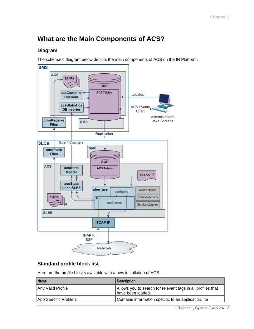
What are the Main Components of ACS?
Diagram
The schematic diagram below depicts the main components of ACS on the IN Platform.
Standard profile block list
Here are the profile blocks available with a new installation of ACS.
Name Description
Any Valid Profile Allows you to search for relevant tags in all profiles that have been loaded.
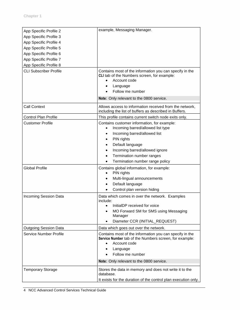
App Specific Profile 1 Contains information specific to an application, for
Chapter 1
4 NCC Advanced Control Services Technical Guide
App Specific Profile 2
App Specific Profile 3
App Specific Profile 4
App Specific Profile 5
App Specific Profile 6
App Specific Profile 7
App Specific Profile 8
example, Messaging Manager.
CLI Subscriber Profile Contains most of the information you can specify in the CLI tab of the Numbers screen, for example:
Account code
Language
Follow me number
Note: Only relevant to the 0800 service.
Call Context Allows access to information received from the network, including the list of buffers as described in Buffers.
Control Plan Profile This profile contains current switch node exits only.
Customer Profile Contains customer information, for example:
Incoming barred/allowed list type
Incoming barred/allowed list
PIN rights
Default language
Incoming barred/allowed ignore
Termination number ranges
Termination number range policy
Global Profile Contains global information, for example:
PIN rights
Multi-lingual announcements
Default language
Control plan version hiding
Incoming Session Data Data which comes in over the network. Examples include:
InitialDP received for voice
MO Forward SM for SMS using Messaging Manager
Diameter CCR (INITIAL_REQUEST)
Outgoing Session Data Data which goes out over the network.
Service Number Profile Contains most of the information you can specify in the Service Number tab of the Numbers screen, for example:
Account code
Language
Follow me number
Note: Only relevant to the 0800 service.
Temporary Storage Stores the data in memory and does not write it to the database.
It exists for the duration of the control plan execution only.
Chapter 1
Chapter 1, System Overview 5
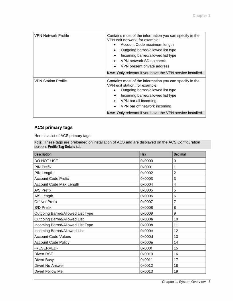
VPN Network Profile Contains most of the information you can specify in the VPN edit network, for example:
Account Code maximum length
Outgoing barred/allowed list type
Incoming barred/allowed list type
VPN network SD no check
VPN present private address
Note: Only relevant if you have the VPN service installed.
VPN Station Profile Contains most of the information you can specify in the VPN edit station, for example:
Outgoing barred/allowed list type
Incoming barred/allowed list type
VPN bar all incoming
VPN bar off network incoming
Note: Only relevant if you have the VPN service installed.
ACS primary tags
Here is a list of ACS primary tags.
Note: These tags are preloaded on installation of ACS and are displayed on the ACS Configuration screen, Profile Tag Details tab.
Description Hex Decimal
DO NOT USE 0x0000 0
PIN Prefix 0x0001 1
PIN Length 0x0002 2
Account Code Prefix 0x0003 3
Account Code Max Length 0x0004 4
A/S Prefix 0x0005 5
A/S Length 0x0006 6
Off Net Prefix 0x0007 7
S/D Prefix 0x0008 8
Outgoing Barred/Allowed List Type 0x0009 9
Outgoing Barred/Allowed List 0x000a 10
Incoming Barred/Allowed List Type 0x000b 11
Incoming Barred/Allowed List 0x000c 12
Account Code Values 0x000d 13
Account Code Policy 0x000e 14
-RESERVED- 0x000f 15
Divert RSF 0x0010 16
Divert Busy 0x0011 17
Divert No Answer 0x0012 18
Divert Follow Me 0x0013 19
Chapter 1
6 NCC Advanced Control Services Technical Guide
Description Hex Decimal
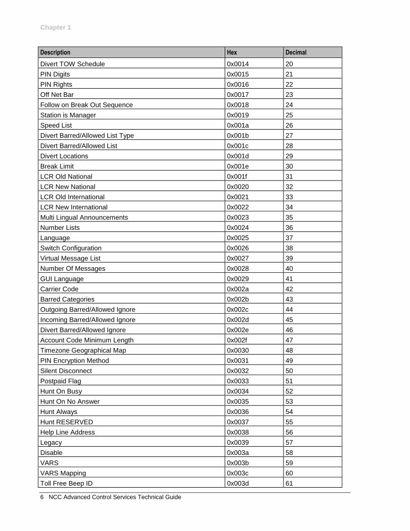
Divert TOW Schedule 0x0014 20
PIN Digits 0x0015 21
PIN Rights 0x0016 22
Off Net Bar 0x0017 23
Follow on Break Out Sequence 0x0018 24
Station is Manager 0x0019 25
Speed List 0x001a 26
Divert Barred/Allowed List Type 0x001b 27
Divert Barred/Allowed List 0x001c 28
Divert Locations 0x001d 29
Break Limit 0x001e 30
LCR Old National 0x001f 31
LCR New National 0x0020 32
LCR Old International 0x0021 33
LCR New International 0x0022 34
Multi Lingual Announcements 0x0023 35
Number Lists 0x0024 36
Language 0x0025 37
Switch Configuration 0x0026 38
Virtual Message List 0x0027 39
Number Of Messages 0x0028 40
GUI Language 0x0029 41
Carrier Code 0x002a 42
Barred Categories 0x002b 43
Outgoing Barred/Allowed Ignore 0x002c 44
Incoming Barred/Allowed Ignore 0x002d 45
Divert Barred/Allowed Ignore 0x002e 46
Account Code Minimum Length 0x002f 47
Timezone Geographical Map 0x0030 48
PIN Encryption Method 0x0031 49
Silent Disconnect 0x0032 50
Postpaid Flag 0x0033 51
Hunt On Busy 0x0034 52
Hunt On No Answer 0x0035 53
Hunt Always 0x0036 54
Hunt RESERVED 0x0037 55
Help Line Address 0x0038 56
Legacy 0x0039 57
Disable 0x003a 58
VARS 0x003b 59
VARS Mapping 0x003c 60
Toll Free Beep ID 0x003d 61
Chapter 1
Chapter 1, System Overview 7
Description Hex Decimal
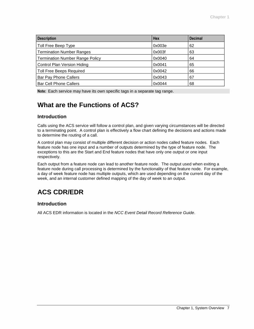
Toll Free Beep Type 0x003e 62
Termination Number Ranges 0x003f 63
Termination Number Range Policy 0x0040 64
Control Plan Version Hiding 0x0041 65
Toll Free Beeps Required 0x0042 66
Bar Pay Phone Callers 0x0043 67
Bar Cell Phone Callers 0x0044 68
Note: Each service may have its own specific tags in a separate tag range.
What are the Functions of ACS?
Introduction
Calls using the ACS service will follow a control plan, and given varying circumstances will be directed to a terminating point. A control plan is effectively a flow chart defining the decisions and actions made to determine the routing of a call.
A control plan may consist of multiple different decision or action nodes called feature nodes. Each feature node has one input and a number of outputs determined by the type of feature node. The exceptions to this are the Start and End feature nodes that have only one output or one input respectively.
Each output from a feature node can lead to another feature node. The output used when exiting a feature node during call processing is determined by the functionality of that feature node. For example, a day of week feature node has multiple outputs, which are used depending on the current day of the week, and an internal customer defined mapping of the day of week to an output.
ACS CDR/EDR
Introduction
All ACS EDR information is located in the NCC Event Detail Record Reference Guide.

Chapter 2, Security Overview 9
Chapter 2
Security Overview
Overview
Purpose
This chapter describes the security features of the Advanced Control Services application.
In this chapter
This chapter contains the following topics.
Security in ACS 9 Defining the Security Levels 10 Setting up ACS Security through SMS 12 Setting up ACS Security without using SMS 16
Security in ACS
Introduction
This chapter describes the ACS security system and gives instructions for its use. ACS will always be installed as a service that is available through Service Management System, but may also be accessed directly.
ACS maintains its own security system, distinct from that of SMS.
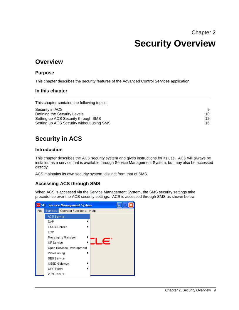
Accessing ACS through SMS
When ACS is accessed via the Service Management System, the SMS security settings take precedence over the ACS security settings. ACS is accessed through SMS as shown below:
Chapter 2
10 NCC Advanced Control Services Technical Guide
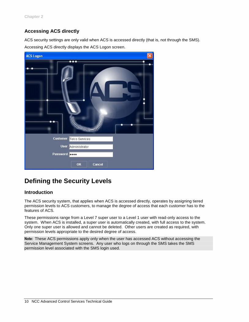
Accessing ACS directly
ACS security settings are only valid when ACS is accessed directly (that is, not through the SMS).
Accessing ACS directly displays the ACS Logon screen.
Defining the Security Levels
Introduction
The ACS security system, that applies when ACS is accessed directly, operates by assigning tiered permission levels to ACS customers, to manage the degree of access that each customer has to the features of ACS.
These permissions range from a Level 7 super user to a Level 1 user with read-only access to the system. When ACS is installed, a super user is automatically created, with full access to the system. Only one super user is allowed and cannot be deleted. Other users are created as required, with permission levels appropriate to the desired degree of access.
Note: These ACS permissions apply only when the user has accessed ACS without accessing the Service Management System screens. Any user who logs on through the SMS takes the SMS permission level associated with the SMS login used.
Chapter 2
Chapter 2, Security Overview 11
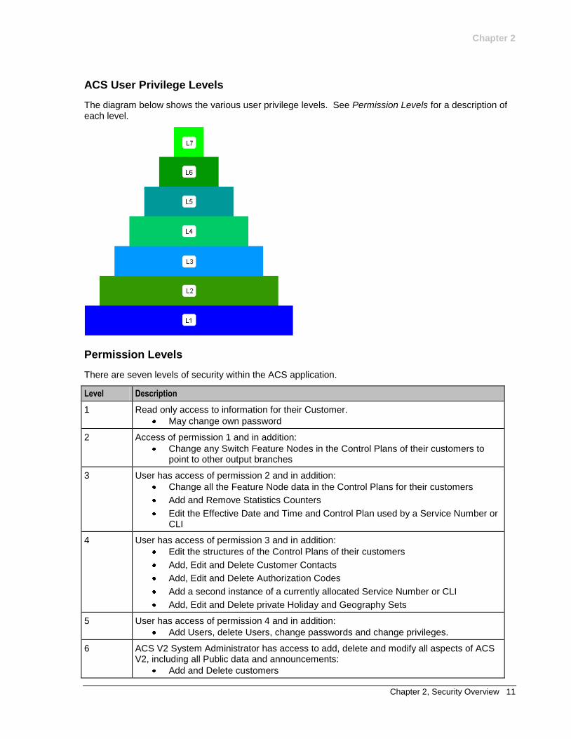
ACS User Privilege Levels
The diagram below shows the various user privilege levels. See Permission Levels for a description of each level.
Permission Levels
There are seven levels of security within the ACS application.
Level Description
1 Read only access to information for their Customer.
May change own password
2 Access of permission 1 and in addition:
Change any Switch Feature Nodes in the Control Plans of their customers to point to other output branches
3 User has access of permission 2 and in addition:
Change all the Feature Node data in the Control Plans for their customers
Add and Remove Statistics Counters
Edit the Effective Date and Time and Control Plan used by a Service Number or CLI
4 User has access of permission 3 and in addition:
Edit the structures of the Control Plans of their customers
Add, Edit and Delete Customer Contacts
Add, Edit and Delete Authorization Codes
Add a second instance of a currently allocated Service Number or CLI
Add, Edit and Delete private Holiday and Geography Sets
5 User has access of permission 4 and in addition:
Add Users, delete Users, change passwords and change privileges.
6 ACS V2 System Administrator has access to add, delete and modify all aspects of ACS V2, including all Public data and announcements:
Add and Delete customers
Chapter 2
12 NCC Advanced Control Services Technical Guide
Level Description
Add and Delete Termination Numbers
Set Resource Allocations for Users
Manage other Customers
Details of the Feature Nodes are fixed and may not be changed
Advanced Editing options on CPE available
7 User has full access to ACS and in addition:
Add and delete other level 6 users
Setting up ACS Security through SMS
Introduction
A Telco must set up SMS users for all users accessing the Service Management System. These SMS users must have a SMS security template assigned to them. All users who access the SMS use the security settings that are set up in the template assigned to them. When accessed through the SMS screens, the SMS security system takes precedence and the following steps are required.
Example:
A Telco may set up an ACS System Administrator template, for users who perform a System Administrator role, perhaps as a Telco help desk operator. The following example shows setting up this ACS System Administrator user to access ACS through the SMS, and then having this user create an ACS Customer.
Procedure
Follow these steps to set the security for a user.
Step Action
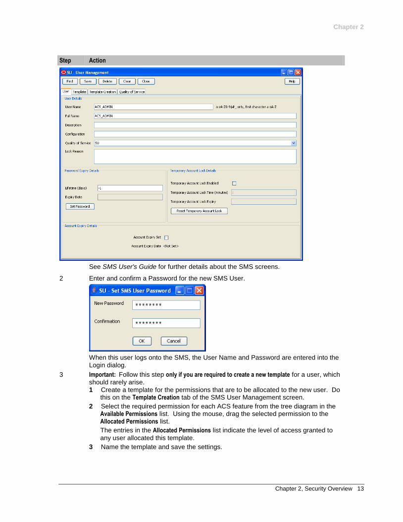
1 Set up an SMS User, using the User tab of the SMS User Management screen.
Chapter 2
Chapter 2, Security Overview 13
Step Action
See SMS User's Guide for further details about the SMS screens.
2 Enter and confirm a Password for the new SMS User.
When this user logs onto the SMS, the User Name and Password are entered into the Login dialog.
3 Important: Follow this step only if you are required to create a new template for a user, which should rarely arise. 1 Create a template for the permissions that are to be allocated to the new user. Do
this on the Template Creation tab of the SMS User Management screen.
2 Select the required permission for each ACS feature from the tree diagram in the Available Permissions list. Using the mouse, drag the selected permission to the Allocated Permissions list.
The entries in the Allocated Permissions list indicate the level of access granted to any user allocated this template.
3 Name the template and save the settings.
Chapter 2
14 NCC Advanced Control Services Technical Guide
Step Action
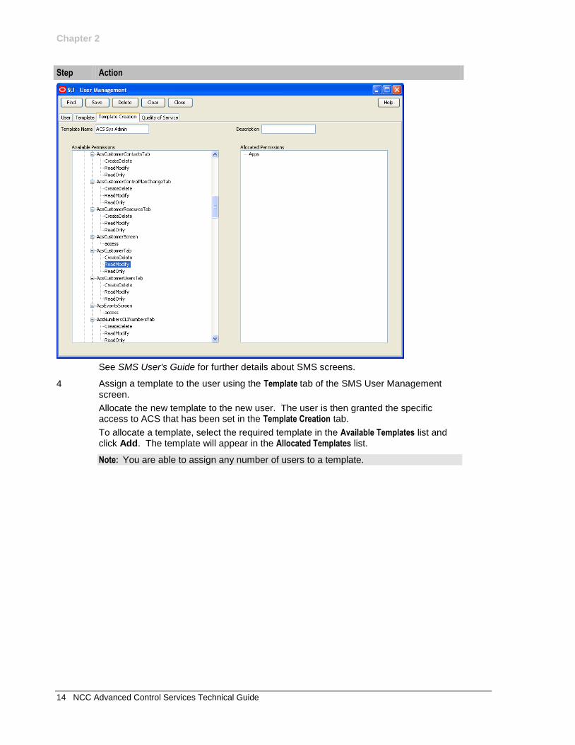
See SMS User's Guide for further details about SMS screens.
4 Assign a template to the user using the Template tab of the SMS User Management screen.
Allocate the new template to the new user. The user is then granted the specific access to ACS that has been set in the Template Creation tab.
To allocate a template, select the required template in the Available Templates list and click Add. The template will appear in the Allocated Templates list.
Note: You are able to assign any number of users to a template.
Chapter 2
Chapter 2, Security Overview 15
Step Action
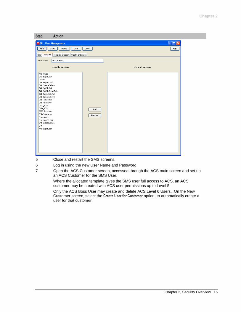
5 Close and restart the SMS screens.
6 Log in using the new User Name and Password.
7 Open the ACS Customer screen, accessed through the ACS main screen and set up an ACS Customer for the SMS User.
Where the allocated template gives the SMS user full access to ACS, an ACS customer may be created with ACS user permissions up to Level 5.
Only the ACS Boss User may create and delete ACS Level 6 Users. On the New Customer screen, select the Create User for Customer option, to automatically create a user for that customer.
Chapter 2
16 NCC Advanced Control Services Technical Guide
Step Action
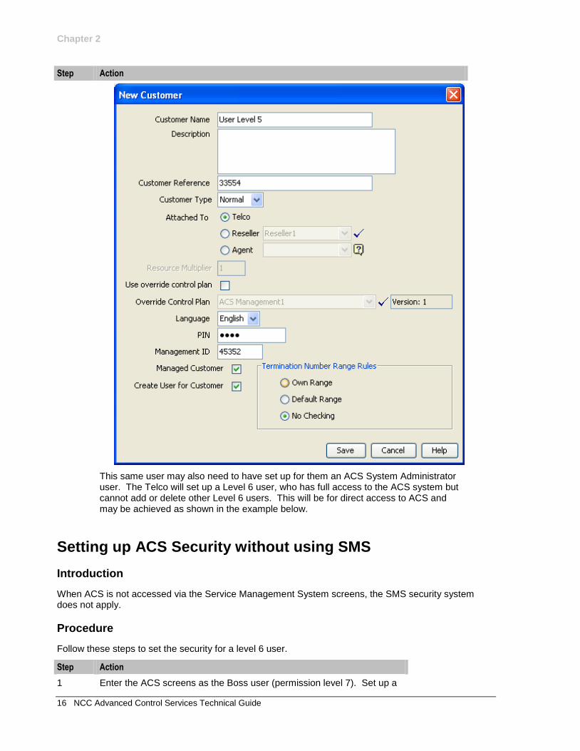
This same user may also need to have set up for them an ACS System Administrator user. The Telco will set up a Level 6 user, who has full access to the ACS system but cannot add or delete other Level 6 users. This will be for direct access to ACS and may be achieved as shown in the example below.
Setting up ACS Security without using SMS
Introduction
When ACS is not accessed via the Service Management System screens, the SMS security system does not apply.
Procedure
Follow these steps to set the security for a level 6 user.
Step Action
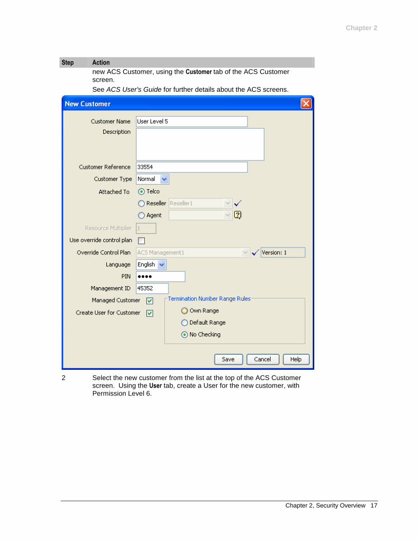
1 Enter the ACS screens as the Boss user (permission level 7). Set up a
Chapter 2
Chapter 2, Security Overview 17
Step Action
new ACS Customer, using the Customer tab of the ACS Customer screen.
See ACS User's Guide for further details about the ACS screens.
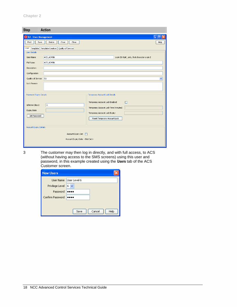
2 Select the new customer from the list at the top of the ACS Customer screen. Using the User tab, create a User for the new customer, with Permission Level 6.
Chapter 2
18 NCC Advanced Control Services Technical Guide
Step Action
3 The customer may then log in directly, and with full access, to ACS (without having access to the SMS screens) using this user and password, in this example created using the Users tab of the ACS Customer screen.
Chapter 3, Configuring the Environment 19
Chapter 3
Configuring the Environment
Overview
Purpose
This chapter describes the steps required to configure ACS.
Configuration file
Many ACS tools and processes depend on a shared configuration file. This file acs.conf is located in the
$(ACS_ROOT)/etc directory. The configuration file consists of several sections named for the
executable they control. Each section contains a name value pair representing a single configuration option.
If the operator changes the acs.conf file, the corresponding service needs to be restarted, so that the configuration file is reread and the changes take effect.
Final configuration
It is important to complete the final configuration of ACS after this chapter. See ACS User's Guide - Setting up ACS for the First Time.
In this chapter
This chapter contains the following topics.
Configuring the Environment 19 Defining the Screen Language 20 Defining the Help Screen Language 22 Setting up the Screens 23
Configuring the Environment
Setting the ACS root directory
The ACS installation depends on a single environment variable to determine the location of the configuration and other support files.
If the software is not installed in the default location, the UNIX system accounts used to execute the service logic and ancillary tools must have this environment variable defined.
The ACS_ROOT variable will only need to be modified if you intend to manually configure two ACS installations side-by-side on the same machine.
Important: This should only be done in consultation with a qualified Oracle engineer.
Chapter 3
20 NCC Advanced Control Services Technical Guide
If you are not required to manually configure two ACS installations, side-by-side, on the same machine the ACS_ROOT variable does not need to be set.
Variable Default Description
ACS_ROOT /IN/service_packages/ACS ACS installation base directory
ACS_ROOT
Description: The ACS installation base directory
Type: String
Optionality: Optional (default used if not set).
Default: /IN/service_packages/ACS
Oracle variables
The ACS account (acs_oper) requires the standard ORACLE environment variables to be present.
Oracle usr/pwd string
While it is possible to specify the usr/pwd string a process uses to connect to Oracle, it is recommended to use the defaults.
Most ACS processes are run by the UNIX user acs_oper. The OPS$ACS_OPER Oracle operator account corresponds to acs_oper. This allows acs_oper to log on to oracle as OPS$ACS_OPER without specifying a user name or password (that is, the process uses the default of "/"). A separate Oracle password is not needed for OPS$ACS_OPER because it is, in Oracle terms, identified externally.
Configuration files
ACS is configured by the following components:
Component Locations Description Further Information
acs.conf all SMSs and VWSs
in the $(ACS_ROOT)/etc directory
This file consists of several sections named for the ACS executable they control. There are different configuration options in the acs.conf on the SMS to the configuration options in the acs.conf on the SLC.
Configuring the acs.conf (on page 57)
SLEE.cfg all SLCs This file sets up SLEE interfaces and applications.
SLEE Technical Guide
eserv.config all SMSs and VWSs
ACS has some additional
configuration in the ACS section of
eserv.config.
eserv.config Configuration (on page 35)
Defining the Screen Language
Introduction
The default language file sets the language which the Java administration screens will start in. The user can change to another language once they have logged in.
The default language can be changed by the system administrator.
Chapter 3
Chapter 3, Configuring the Environment 21
By default, the language is set to English. If English is your preferred language, you can skip this step and proceed to the next configuration task: Defining the Help Screen Language.
Default.lang
When ACS is installed, a file called Default.lang is created in the application's language directory in the screens module. This contains a soft-link to the language file that defines the language that will be used by the ACS UI.
If a Default.lang file is:
Not present, the English.lang file will be used
Present, a user must explicitly set their language to their required language in the Tools screen or the default language will be used
The ACS Default.lang file is located in the following directory:
/IN/html/Acs_Service/language/
Example screen language
If Dutch is the language you want to set as the default, create a soft-link from the Default.lang file to the Dutch.lang file.
Procedure
Follow these steps to set the default language for your ACS user interface (UI).
Step Action
1 Go to the following directory:
/IN/html/Acs_Service/language
Example command: cd /IN/html/Acs_Service/language
2 Ensure the Default.lang file exists in this directory.
3 If the required file does not exist, create an empty file called Default.lang.
4 Ensure that the language file for your language exists in this directory. The file should be in the format: language.lang
Where:
language is your language.
Example:
Spanish.lang
5 If the required language file does not exist, perform one of the following actions:
Create a new one with your language preferences
Contact Oracle support.
To create a language file, you will need a list of the phrases and words used in the screens. These should appear in a list with the translated phrase in the following format: original phrase=translated phrase
Any existing language file should have the full set of phrases. If you do not have an existing file to work from, contact Oracle support.
6 Create a soft link between the Default.lang file, and the language file you want to use as the default language for the SMS UI.
Example command:
Chapter 3
22 NCC Advanced Control Services Technical Guide
ln -s Dutch.lang Default.lang
Defining the Help Screen Language
Introduction
The default Helpset file sets the language which the help system for the Java Administration screens will start in. The user can change to another language once they have logged in.
The default language can be changed by the system administrator. By default, the language is set to English.
Default_Acs_Service.hs
When ACS is installed, a file called Default_Acs_Service.hs is created in the application's language directory in the screens module. This contains a soft-link to the language file which defines the language that will be used by the ACS UI.
If a Default_Acs_Service.hs file is:
Not present, the English_Acs_Service.hs file will be used
Present, a user must explicitly set their language to their required language in the Tools screen or the default language will be used.
The Default_Acs_Service.hs file is located in the following directory:
/IN/html/Acs_Service/helptext/.
Example helpset language
If Dutch is the language you want to set as the default, create a soft-link from the Default_Acs_Service.hs file to the Dutch_Acs_Service.hs file.
Procedure
Follow these steps to set the default language for your ACS user interface (UI).
Step Action
1 Go to the following directory:
/IN/html/Acs_Service/helptext
Example command: cd /IN/html/Acs_Service/helptext
2 Check to see if the Default_Acs_Service.hs file exists in this directory.
3 If the required file does not exist, create an empty file called Default_Acs_Service.hs.
4 Check if the language file for your language exists in this directory. The file should be in the format: language_Acs_Service.hs
Where:
language is your language.
Example:
Dutch_Acs_Service.hs
5 If the required language file does not exist, perform one of the following actions:
Create a new one with your language preferences
Contact Oracle support.
Chapter 3
Chapter 3, Configuring the Environment 23
To create a language file, you will need a list of the phrases and words used in the screens. These should appear in a list with the translated phrase in the following format: original phrase=translated phrase
Any existing language file should have the full set of phrases. If you do not have an existing file to work from, contact Oracle support.
6 Create a soft link between the Default_Acs_Service.hs file, and the language file you want to use as the default language for the ACS UI.
Example command: ln -s Dutch_Acs_Service.hs Default_Acs_Service.hs
Setting up the Screens
Accessing ACS
There are several ways to access the ACS user interface (UI) using an Internet browser. For example, by using:
Java Webstart to open the Service Management System default page at
http://SMS_hostname/index.html, and then clicking on the WebStart link.
Where:
SMS_hostname is the hostname of an SMS platform in the IN.
ACS Webstart directly by entering the following url:
http://SMS_hostname/acs.jnlp
The Service Management System application, and selecting ACS Service from the Services menu.
You can also start the ACS UI from the Windows command line by entering the following command:
c:\> javaws http://SMShostname/acs.jnlp
Where SMShostname is the hostname of an SMS in the IN.
For more information about the ACS UI, see ACS User's Guide.
About customizing the ACS UI
You can customize the ACS UI by setting Java applet parameters in the following files located in the /IN/html/ directory:
acs.jnlp
sms.jnlp
You use the following syntax to set a Java applet parameter in the acs.jnlp or the sms.jnlp file:
<param name="parameter" value="value" />
Where:
parameter is the name of the Java applet parameter
value is the value to which that parameter will be set
Important: Some Java applet parameters may be set in both the acs.jnlp file and in the sms.jnlp file. You must specify the same value for Java applet parameters in both files.
About applet parameters in .html files
The ability to customize the NCC UI by setting applet parameters in the following .html files has been deprecated:
Chapter 3
24 NCC Advanced Control Services Technical Guide
acs.html
sms.html
vpn.html
If you upgraded from an earlier version of NCC, you may continue to set applet parameters in these files. However, you must ensure that any parameters that you set are also set to the same value in the corresponding .jnlp file:
acs.jnlp
sms.jnlp
vpn.jnlp
Note: You use the following syntax to set applet parameters in the .html files: <param name=parameter value="value">
Where:
parameter is the name of the Java applet parameter
value is the value to which that parameter will be set
Java applet parameters
The following applet parameters are available to customize the UI:
allowCallPlanSchedulingInPast
Syntax: See example
Description: If set to true, control plans are allowed to be scheduled to be effective in the past.
Type: String
Optionality: Optional
Allowed: True
t(rue)
Yes
y(es)
1
All other values are considered to be false.
Default: True
Notes:
Example: <param name="allowCallPlanSchedulingInPast" value="t" />
allowRefInCustCombo
Syntax: See example
Description: If set to true this allows the searchable Customer combo field at the top of each top-level ACS screen to be used to search using the Customer Reference as an alternative to searching using the Customer Name.
Type: String
Optionality: Optional
Allowed: True
t(rue)
Yes
y(es)
1
All other values are considered to be false.
Chapter 3
Chapter 3, Configuring the Environment 25
Default: False
Notes:
Example: <param name="allowRefInCustCombo" value="t" />
autoCloseCompilerDialog
Syntax: See example
Description: If set to true, the compiler dialog will automatically close on successful compile of a control plan.
Type: String
Optionality: Optional
Allowed: True
t(rue)
Yes
y(es)
1
All other values are considered to be false.
Default: False
Notes:
Example: <param name="autoCloseCompilerDialog" value="t" />
autoCloseCPE
Syntax: See example
Description: If set to true the CPE will automatically close on successful compile of a control plan.
Type: String
Optionality: Optional
Allowed: True
t(rue)
Yes
y(es)
1
All other values are considered to be false.
Default: False
Notes:
Example: <param name="autoCloseCPE" value="t" />
defaultTelcoManaged
Syntax: See example
Description: If set to true all ACS customers will be created with the Managed Customer check box selected by default.
Type: String
Optionality: Optional
Allowed: True
t(rue)
Yes

Chapter 3
26 NCC Advanced Control Services Technical Guide
y(es)
1
All other values are considered to be false.
Default: True
Notes:
Example: <param name="defaultTelcoManaged" value="f" />
issuePCClockWarning
Syntax: See example
Description: If true and the user's PC clock time is different by more than two minutes to the SMS platform's clock time, a warning is given.
Type: String
Optionality: Optional
Allowed: True
t(rue)
Yes
y(es)
1
All other values are considered to be false.
Default: True
Notes: The time difference limit is 120 seconds slower or faster.
Example: <param name="issuePCClockWarning" value="t" />
logo
Syntax: See example
Description: Sets the system graphic that displays briefly in a splash window immediately before the Login window displays. At installation, the logo parameter is set to the .gif file for the Oracle logo.
Type: String
Optionality: Optional
Allowed: A valid network path/file.
Default: None
Notes: Set to the relative path name for the logo .gif file to use.
Example: <param name="logo" value="SMS/images/oracle.gif" />
MAX_CONTROL_PLANS_DISPLAYED
Syntax: See example
Description: Sets the maximum number of control plans visible in the search box.
Type: String
Optionality: Optional
Allowed:
Default:
Notes:
Example: <param name="MAX_CONTROL_PLANS_DISPLAYED" value="200" />
Chapter 3
Chapter 3, Configuring the Environment 27
maximiseAcsScreens
Syntax: See example
Description: Sets the whether the windows in the ACS UI will be opened at maximum size or optimum size.
Type: String
Optionality: Optional
Allowed: True
t(rue)
Yes
y(es)
1
All other values are considered to be false.
Default: False
Notes: If set to:
True, the windows in the ACS UI will be opened maximized.
False, the windows in the ACS UI will be opened at optimum size.
Example: <param name="maximiseAcsScreens" value="t" />
paletteStyle
Syntax: See example
Description: Set to "old" to display the feature palette in the Control Plan Editor window using
the static panel style.
Type: String
Optionality: Optional
Allowed: old
Default: Defaults to the floating panel style feature palette in the Control Plan Editor
window when the paletteStyle parameter is not set.
Notes: The floating panel style feature palette displays feature group names in a list, and the feature nodes within a selected group in a floating panel. You can filter the available feature nodes using the Search Palette feature.
The static panel style feature palette displays an expandable list of node groups from which you select individual feature nodes in a static panel. The Search Palette feature is not available with this style.
To enable the paletteStyle parameter configuration, you should clear
the Java cache and the client browser cache before restarting the Control Plan Editor.
Example: <param name="paletteStyle" value="old" />
Profile
Syntax: param name="Profilenumber" value="new_name"
Description: Use to either suppress or change the name of any of the 20 profile blocks.
Type: String
Optionality: Optional
Allowed: 1 number 20
new_name is one of the following:
- (dash)
Chapter 3
28 NCC Advanced Control Services Technical Guide
string comprising any printable characters.
Default: The following table lists default profile block names in the order in which they are displayed in the relevant feature node drop down lists.
Profile1 VPN Network Profile
Profile2 VPN Station Profile
Profile3 Customer Profile
Profile4 Control Plan Profile
Profile5 Global Profile
Profile6 CLI Subscriber Profile
Profile7 Service Number Profile
Profile8 App Specific 1
Profile9 App Specific 2
Profile10 App Specific 3
Profile11 App Specific 4
Profile12 App Specific 5
Profile13 App Specific 6
Profile14 App Specific 7
Profile15 App Specific 8
Profile16 Any Valid Profile
Profile17 Temporary Storage
Profile18 Call Context
Profile19 Outgoing Extensions
Profile20 Incoming Extensions
Notes: If you set new_name to - (a dash), the profile block will not display in the
screens.
If VPN is not installed, profile numbers Profile1 and Profile2 are suppressed by default.
If Charging Control Services is installed, profile block names associated with profile numbers Profile8 through Profile15 are automatically changed. For more information, see CCS Technical Guide.
If RCA is not installed, profile numbers Profile19 and Profile20 are suppressed by default. They can be made available by installing RCA or by appending them to the sms.jnlp file.
Feature nodes with writable fields cannot access Profile16 to write into.
Examples: <param name="Profile1" value="-" />
<param name="Profile6" value="Originating CLI" />
requireCustomerReference
Syntax: See example
Description: If set to true a customer reference is created for every new ACS customer created.
Type: String
Optionality: Optional
Chapter 3
Chapter 3, Configuring the Environment 29
Allowed: True
t(rue)
Yes
y(es)
1
All other values are considered to be false.
Default: True
Notes: The customer may not be saved until the Customer Reference field has been populated.
Example: <param name="requireCustomerReference" value="f" />
scfs
Syntax: <param name="scfs" value="scf1,scf2,...,scfn" />
Description: A list of the network entities available to hand over to. For every entry in the .jnlp file, a matching scf entry must be created in the acs.conf file on each SLC defining the address associated with this scf entry.
Type: String
Optionality: Optional, but TCAP Handover node will not work without at least one scf.
Allowed: Any scf name configured in the acs.conf file. See acsChassis SCF Configuration (SCP) (see "acsChassis SSF Configuration (SLC)" on page 117).
Default: None
Notes: The scfs names listed in this section are used by the following feature nodes:
TCAP Handover node as the SCP Name list
RIMS MAP Query and IS41 Query nodes as the Return Address for mapping the SCCP Calling Party Address
Example: <param name="scfs" value="SCF_Name1,SCF_Name2" />
showAnnouncementSource
Syntax: See example
Description: If set to true the Announcement Source (Resource Name and Resource ID) will display in brackets next to the Announcement Name, in all Announcement Entry list boxes.
Type: String
Optionality: Optional
Allowed: TRUE
true
YES
yes
Y
y
All other values are considered to be false.
Default: True
Notes:
Example: <param name="showAnnouncementSource" value="f" />
Chapter 3
30 NCC Advanced Control Services Technical Guide
showCallPlanCopy
Syntax: See example
Description: If set to false the Copy button on the ACS Numbers screen is disabled.
Type: String
Optionality: Optional
Allowed: True
t(rue)
Yes
y(es)
1
All other values are considered to be false.
Default: True
Notes:
Example: <param name="showCallPlanCopy" value="f" />
showNetwork
Syntax: See example
Description: If set to true the Networks field will be displayed in the New ACS Customer dialog.
Type: String
Optionality: Optional
Allowed: True
t(rue)
Yes
y(es)
1
All other values are considered to be false.
Default: True
Notes:
Example: <param name="showNetwork" value="f" />
ssfs
Syntax: <param name="ssfs" value="ssf1,ssf2,...,ssfn" />
Description: A list of available switches in the IN network.
Type: String
Optionality: Optional, but the Call Initiation node will not work without at least one ssf.
Allowed: Any ssf name configured in the acs.conf file. See acsChassis SSF Configuration (SCP) (see "acsChassis SSF Configuration (SLC)" on page 117).
Default: None
Notes: The ssfs names listed here are used by the Call Initiation feature node as the Switch Name list.
Example: <param name="ssfs" value="SSF_Name1,SSF_Name2" />
suppressedSDRDigits
Syntax: See example
Description: Allows the system administrator to specify which digits and special characters are allowed in the Selection Dependant Routing feature node. The specified values

Chapter 3
Chapter 3, Configuring the Environment 31
are suppressed, and are not available for selection in the Selection Dependant Routing feature node.
Type: String
Optionality: Optional
Allowed: 0-9, a-f, *, #
Default: None
Notes:
Example: <param name="suppressedSDRDigits" value="12ab" />
SuppressTagID
Syntax: See example
Description: If the SuppressTagID parameter evaluates to true then the profile tag value is
suppressed, and only the profile field name displays in profile field lists in the UI. When set to false the profile field name and profile tag value displays.
For example, when SuppressTagID is set to:
true – the profile tag 196613 displays the name "PIN Prefix"
false – the profile tag 196613 displays the name "PIN Prefix
(196613)"
Type: Boolean
Optionality: Optional
Allowed: The following case-insensitive values evaluate to true:
true
t
yes
y
1
All other values evaluate to false.
Default: true
Notes:
Example: <param name="SuppressTagID" value="TRUE" />
TZ
Syntax: See example
Description: The screens in the NCC UI display all time and date values in the time zone set by this parameter.
Type: String
Optionality: Optional (default used if not set)
Allowed: Any Java supported time zone.
Default: GMT
Notes: For a full list a Java supported time zones see Time Zones (on page 183) in the appendix in ACS Technical Guide.
Example: <param name="TZ" value="GMT" />
Chapter 3
32 NCC Advanced Control Services Technical Guide
updateCPReferences
Syntax: See example
Description: If set to true and the answer to the question at installation time "Do you want automatic Control Plan deletion and Service Number updating installed?" was 'No', the following will happen.
A dialog will be displayed on successful compilation of a control plan to allow the user to select which service numbers are to use the new version of the control plan as their scheduled control plan.
Type: String
Optionality: Optional
Allowed: True
t(rue)
Yes
y(es)
1
All other values are considered to be false.
Default: None
Notes:
Example: <param name="updateCPReferences" value="t" />
useTNForNodeName
Syntax: <param name="useTNForNodeName" value="true|false" />
Description: If set to true the Node name field for an Unconditional Termination (UT) feature node, or an Attempt Termination (AT) feature node, appears grayed out and the Termination Number (TN) configured for the feature node is displayed as the feature node name in the Control Plan Editor (CPE) window. The TN is displayed for any UT or AT feature node in the CPE canvas, without requiring you to save each feature node to update the
stored control plan data. Unsetting the useTNForNodeName parameter reverts the
CPE to display the stored feature node name, unless the feature node has been opened, saved and compiled again, thereby updating the stored control plan data.
Type: Boolean
Optionality: Optional (default used if not set)
Allowed: True
t(rue)
Yes
y(es)
1
All other values are considered to be false.
Default: False
Notes: You can update the TN for an UT feature node, or an AT feature node, in a control plan by updating the TN in the ACS Numbers screen. See the discussion on Editing Termination Numbers in NCC Advanced Control Services User's Guide for more information. If you use this method to update the TN, then enabling the
useTNForNodeName parameter ensures that the configured TN for the UT, or AT
feature node displays in the CPE window.
Example: <param name="useTNForNodeName" value="true" />
Chapter 3
Chapter 3, Configuring the Environment 33
Example jnlp applet parameters
Here is an example acs.jnlp file showing the applet parameter settings at installation.
<jnlp spec="1.0+"
codebase="http://HOST_IP_ADDR/"
href="acs.jnlp" >
.
.
.
<resources>
<j2se version="J2SEVERSION" href="http://java.sun.com/products/autodl/j2se"
/>
<property name="jnlp.packEnabled" value="true"/>
<jar href="sms.sig.jar" />
<jar href="acs.sig.jar" />
<jar href="common.sig.jar" />
<jar href="ojdbc6.sig.jar" />
<jar href="jchart.sig.jar" />
<jar href="ohj.sig.jar" />
<jar href="help-share.sig.jar" />
<jar href="oracle_ice.sig.jar" />
<jar href="jewt..sig.jar" />
<jar href="share.jar.sig" />
<jar href="osd.sig.jar" />
<jar href="rims.sig.jar" />
<jar href="xms.sig.jar" />
<jar href="ses.sig.jar" />
<property name="java.util.Arrays.useLegacyMergeSort" value="true" />
</resources>
<applet-desc
documentBase="http://HOST_IP_ADDR"
name="ACSApplet"
main-class="com.g8labs.acs.coreScreens.AcsApplet"
width="275"
height="25" >
<param name="TZ" value="GMT" />
<param name="host" value="HOST_IP_ADDR" />
<param name="port" value="LPORT" />
<param name="database" value="DB_SID" />
<param name="dBUser" value="acs_public" />
<param name="dBPassword" value="acs_public" />
<param name="INProtocol" value="" />
<param name="UseAnnouncements" value="YES" />
<param name="SuppressTagID" value="TRUE" />
<param name="Profile8" value="Account Reference Profile" />
<param name="Profile9" value="Product Type Profile" />
<param name="Profile10" value="Control Plan Profile (App 3)" />
<param name="Profile12" value="CCS Global Profile" />
<param name="Profile13" value="CCS Temporary Profile (App 6)" />
<param name="Profile14" value="CCS Temporary Profile (App 7)" />
<param name="Profile15" value="CCS Temporary Profile (App 8)" />
</applet-desc>
</jnlp>
For a definition of parameters that are not listed in this section of the ACS Technical Guide, see SMS Technical Guide.

Chapter 4, Configuring the eserv.config 35
Chapter 4
Configuring the eserv.config
Overview
Introduction
This chapter explains how to configure the ACS section of the eserv.config.
In this chapter
This chapter contains the following topics.
eserv.config Configuration 35 ACS Configuration in the eserv.config File 36 MRC Configuration 53
eserv.config Configuration
Introduction
The eserv.config file is a shared configuration file, from which many NCC applications read their configuration. Each NCC machine (SMS, SLC, and VWS) has its own version of this configuration file, containing configuration relevant to that machine. The eserv.config file contains different sections; each application reads the sections of the file that contains data relevant to it.
The eserv.config file is located in the /IN/service_packages/ directory.
The eserv.config file format uses hierarchical groupings, and most applications make use of this to divide up the options into logical groupings.
Configuration file format
To organize the configuration data within the eserv.config file, some sections are nested within other sections. Configuration details are opened and closed using either { } or [ ].
Groups of parameters are enclosed with curly brackets - { }
An array of parameters is enclosed in square brackets - [ ]
Comments are prefaced with a # at the beginning of the line
To list things within a group or an array, elements must be separated by at least one comma or at least one line break. Any of the following formats may be used, as in this example:
{ name="route6", id = 3, prefixes = [ "00000148", "0000473"] }
{ name="route7", id = 4, prefixes = [ "000001049" ] }
or
{ name="route6"
id = 3
prefixes = [
"00000148"
"0000473"
]
}
Chapter 4
36 NCC Advanced Control Services Technical Guide
{ name="route7"
id = 4
prefixes = [
"000001049"
]
}
or
{ name="route6"
id = 3
prefixes = [ "00000148", "0000473" ]
}
{ name="route7", id = 4
prefixes = [ "000001049" ]
}
Editing the file
Open the configuration file on your system using a standard text editor. Do not use text editors, such as Microsoft Word, that attach control characters. These can be, for example, Microsoft DOS or Windows line termination characters (for example: ^M), which are not visible to the user, at the end of each row. This will cause file errors when the application tries to read the configuration file.
Always keep a backup of your file before making any changes to it. This will ensure you have a working copy to which you can return.
eserv.config files delivered
Most applications come with an example eserv.config configuration in a file called eserv.config.example in the root of the application directory, for example, /IN/service_packages/eserv.config.example.
ACS Configuration in the eserv.config File
ACS section
The ACS section is part of of the eserv.config file. See Example ACS configuration in eserv.config (on page
51) for a detailed example of the parameters.
Reread the configuration by sending a SIGHUP to slee_acs.
Here is the high-level structure of the section.
ACS = {
countryCodes = [codes]
macroNodes = {
macronodes_parameters
}
tracing = {
tracing_parameters
}
acsChassisActions = {
acsChassisActions_parameters
}
SessionTimeInformation = {
SessionTimeInformation_parameters
}
ServiceEntries = [
{
Chapter 4
Chapter 4, Configuring the eserv.config 37
ServiceEntries_parameters
}
]
acsTriggerIF = {
acsTriggerIF_parameters
}
}
countryCodes
Syntax: countryCodes = [codes]
Description: The list of country codes supported for location number normalization.
Type: Array
Optionality: Optional (default used if not set).
Allowed: International country codes
Default:
Notes: This is used when roaming to determine the location of the caller and add country code to called number if appropriate.
Example: countryCodes = [ "61" # Australia "64" # New Zealand "65" # Singapore "44" # United Kingdom "1" # USA/Canada ]
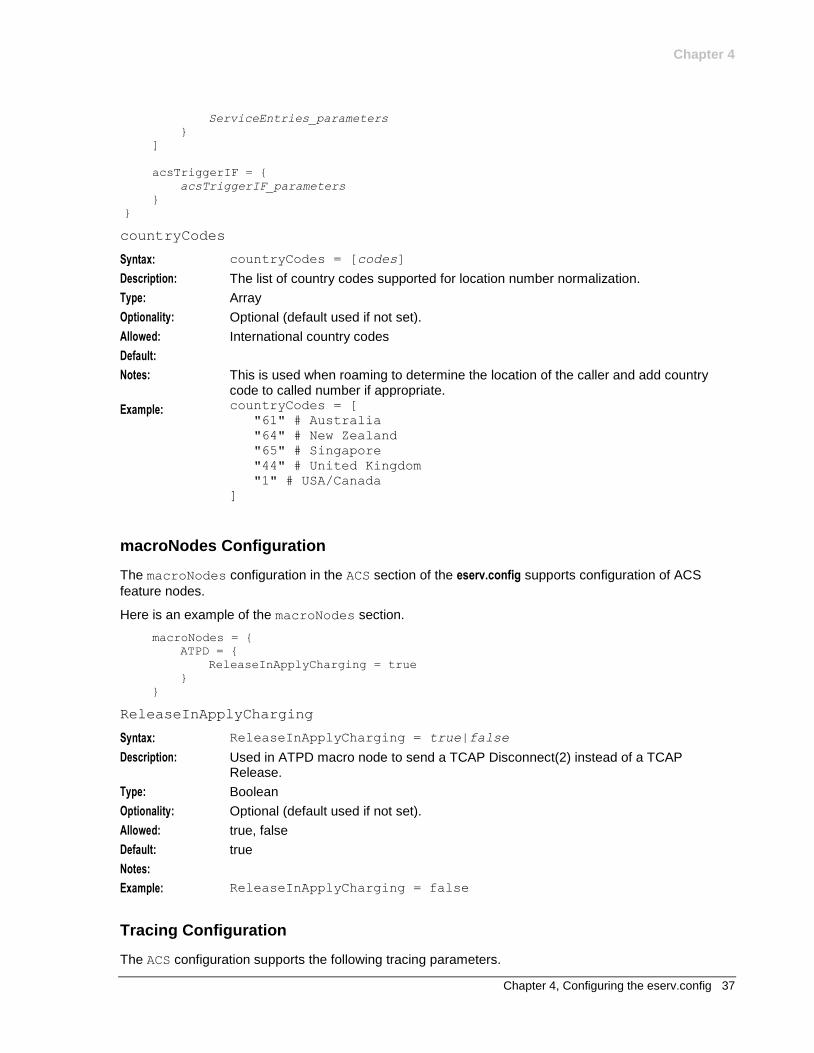
macroNodes Configuration
The macroNodes configuration in the ACS section of the eserv.config supports configuration of ACS
feature nodes.
Here is an example of the macroNodes section.
macroNodes = {
ATPD = {
ReleaseInApplyCharging = true
}
}
ReleaseInApplyCharging
Syntax: ReleaseInApplyCharging = true|false
Description: Used in ATPD macro node to send a TCAP Disconnect(2) instead of a TCAP Release.
Type: Boolean
Optionality: Optional (default used if not set).
Allowed: true, false
Default: true
Notes:
Example: ReleaseInApplyCharging = false
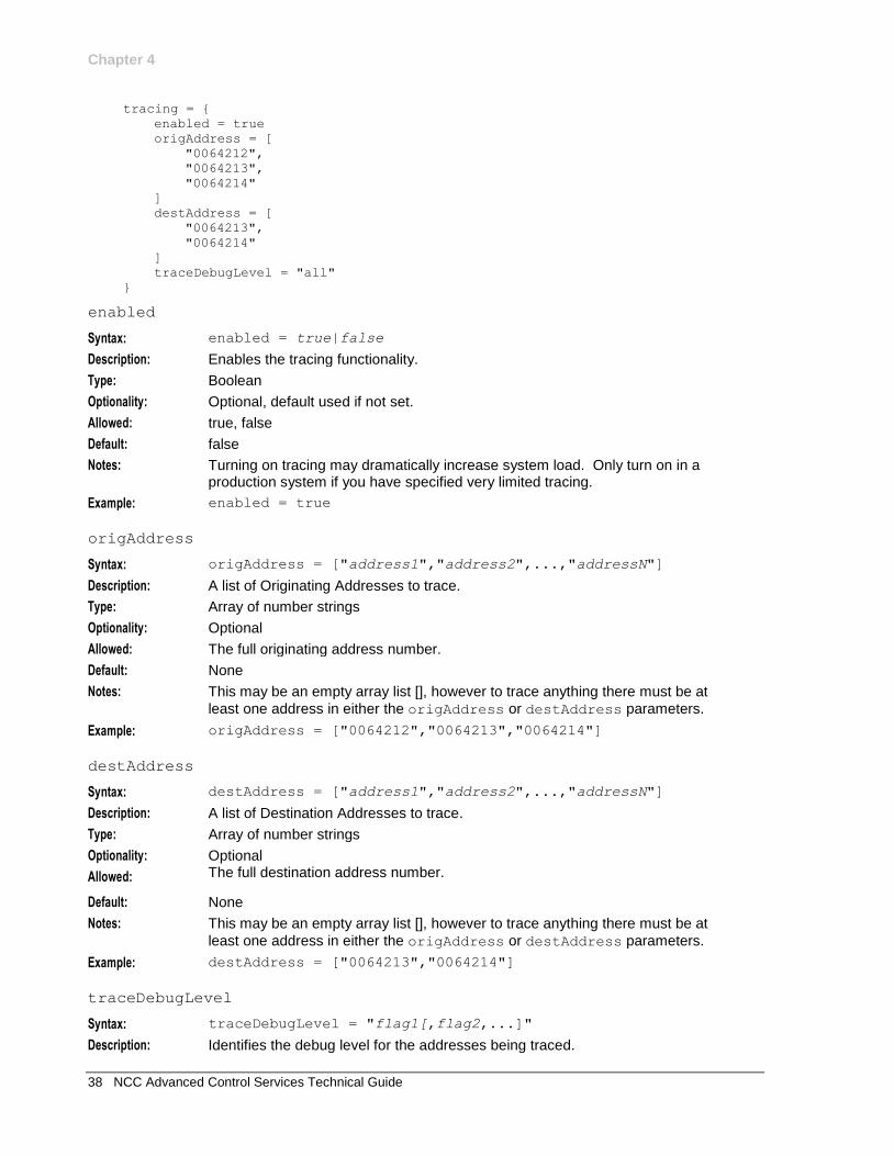
Tracing Configuration
The ACS configuration supports the following tracing parameters.
Chapter 4
38 NCC Advanced Control Services Technical Guide
tracing = {
enabled = true
origAddress = [
"0064212",
"0064213",
"0064214"
]
destAddress = [
"0064213",
"0064214"
]
traceDebugLevel = "all"
}
enabled
Syntax: enabled = true|false
Description: Enables the tracing functionality.
Type: Boolean
Optionality: Optional, default used if not set.
Allowed: true, false
Default: false
Notes: Turning on tracing may dramatically increase system load. Only turn on in a production system if you have specified very limited tracing.
Example: enabled = true
origAddress
Syntax: origAddress = ["address1","address2",...,"addressN"]
Description: A list of Originating Addresses to trace.
Type: Array of number strings
Optionality: Optional
Allowed: The full originating address number.
Default: None
Notes: This may be an empty array list [], however to trace anything there must be at
least one address in either the origAddress or destAddress parameters.
Example: origAddress = ["0064212","0064213","0064214"]
destAddress
Syntax: destAddress = ["address1","address2",...,"addressN"]
Description: A list of Destination Addresses to trace.
Type: Array of number strings
Optionality: Optional
Allowed: The full destination address number.
Default: None
Notes: This may be an empty array list [], however to trace anything there must be at
least one address in either the origAddress or destAddress parameters.
Example: destAddress = ["0064213","0064214"]
traceDebugLevel
Syntax: traceDebugLevel = "flag1[,flag2,...]"
Description: Identifies the debug level for the addresses being traced.
Chapter 4
Chapter 4, Configuring the eserv.config 39
Type: String
Optionality: Mandatory (if enabled=true)
Allowed: Any valid flag.
A useful method of finding which flags are relevant to the tracing you want to do is to: 1 Run your call on a model environment with DEBUG=all
Result: Debug will report all relevant sections.
2 Check through the debug and identify which sections to report or suppress.
3 Change the debug settings.
4 Rerun the call.
Default: "all,-COMMON_escher_detail,-COMMON_escher_dump,-slee_api,-cmnTimeout,-cmnCacheDetail,-Config,-beVWARS_detail,-beSyncDetail"
Notes: traceDebugLevel = flag turns only flag on.
traceDebugLevel=all,-flag,-flag2 turns all debug on, and then turns flag and
flag2 off.
Any section can be removed from the trace by preceding with a minus sign.
The output columns are also configurable, and can be turned off.
By default the columns are: date file line pid section message
Columns in output are:
* display:name the program name registered with
cmnErrorSetProgram(), off by default
* display:date the date in YYYY/MM/DD HH:MM:SS format
* display:file the source filename
* display:line the source line number
* display:pid the process ID
* display:section the debug section
The parameter string value must be enclosed in quotes.
Examples: traceDebugLevel="all"
Traces everything for the original and or destination addresses.
traceDebugLevel="cmnConfig,slee_api"
Traces cmnConfig and slee_api sections for the original and or destination addresses.
traceDebugLevel="all,-cmnEscher"
Traces everything except cmnEscher section for the original and or destination addresses.
traceDebugLevel="all,-cmnEscher,-display:file"
Traces everything except cmnEscher section for the original and or destination addresses, and removes the file column from the output.
acsChassisActions Configuration
Here is a an example of the acsChassisActions configuration of the ACS section of the eserv.config.
acsChassisActions = {
mscAddressForEdr = [
{
mscAddress = "123456789"
encoding = "BCD"
},
{
Chapter 4
40 NCC Advanced Control Services Technical Guide
mscAddress = "987654321"
encoding = "ASCII"
}
]
}
encoding
Syntax: encoding = "code"
Description: The encoding of the MSC address
Type: String
Optionality: Optional
Allowed: Values:
"BCD" (Binary Coded Decimal)
"ASCII"
Default: BCD
Notes: Member of mscAddressForEdr (on page 40) array
Example: encoding = "BCD"
mscAddress
Syntax: mscAddress = "addr"
Description: The MSC address (in the CallReferenceNumber)
Type: String
Optionality: Optional
Allowed:
Default:
Notes: Member of mscAddressForEdr (on page 40) array
Example: mscAddress = "123456789"
mscAddressForEdr
Syntax: mscAddressForEdr = [addr_parameters]
Description: Array of MSC addresses and their encoding. This is used by the Add EDR Field chassis action.
Type: Array
Optionality: Optional (default used if not set).
Allowed:
Default: All mscAddresses are encoded as BCD.
Notes:
Example: mscAddressForEdr = [ { mscAddress = "123456789" encoding = "BCD" } ]
Chapter 4
Chapter 4, Configuring the eserv.config 41
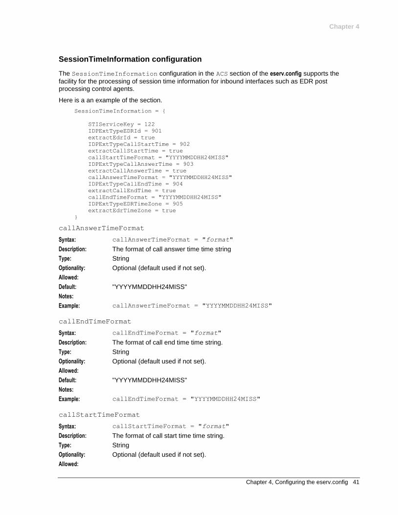
SessionTimeInformation configuration
The SessionTimeInformation configuration in the ACS section of the eserv.config supports the
facility for the processing of session time information for inbound interfaces such as EDR post processing control agents.
Here is a an example of the section.
SessionTimeInformation = {
STIServiceKey = 122
IDPExtTypeEDRId = 901
extractEdrId = true
IDPExtTypeCallStartTime = 902
extractCallStartTime = true
callStartTimeFormat = "YYYYMMDDHH24MISS"
IDPExtTypeCallAnswerTime = 903
extractCallAnswerTime = true
callAnswerTimeFormat = "YYYYMMDDHH24MISS"
IDPExtTypeCallEndTime = 904
extractCallEndTime = true
callEndTimeFormat = "YYYYMMDDHH24MISS"
IDPExtTypeEDRTimeZone = 905
extractEdrTimeZone = true
}
callAnswerTimeFormat
Syntax: callAnswerTimeFormat = "format"
Description: The format of call answer time time string
Type: String
Optionality: Optional (default used if not set).
Allowed:
Default: "YYYYMMDDHH24MISS"
Notes:
Example: callAnswerTimeFormat = "YYYYMMDDHH24MISS"
callEndTimeFormat
Syntax: callEndTimeFormat = "format"
Description: The format of call end time time string.
Type: String
Optionality: Optional (default used if not set).
Allowed:
Default: "YYYYMMDDHH24MISS"
Notes:
Example: callEndTimeFormat = "YYYYMMDDHH24MISS"
callStartTimeFormat
Syntax: callStartTimeFormat = "format"
Description: The format of call start time time string.
Type: String
Optionality: Optional (default used if not set).
Allowed:
Chapter 4
42 NCC Advanced Control Services Technical Guide
Default: "YYYYMMDDHH24MISS"
Notes:
Example: callStartTimeFormat = "YYYYMMDDHH24MISS"
extractCallAnswerTime
Syntax: extractCallAnswerTime = true|false
Description: Enable or disable extraction of call answer time from IDP extension.
Type: Boolean
Optionality: Optional (default used if not set).
Allowed: true, false
Default: true
Notes:
Example: extractCallAnswerTime = true
extractCallEndTime
Syntax: extractCallEndTime = true|false
Description: Enable or disable extraction of EDR ID from IDP extension
Type: Boolean
Optionality: Optional (default used if not set).
Allowed: true, false
Default: true
Notes:
Example: extractCallEndTime = true
extractCallStartTime
Syntax: extractCallStartTime = true|false
Description: Enable or disable extraction of call start time from IDP extension
Type: Boolean
Optionality: Optional (default used if not set).
Allowed: true, false
Default: true
Notes:
Example: extractCallStartTime = true
extractEdrId
Syntax: extractEdrId = true|false
Description: Enable or disable extraction of EDR ID from IDP extension.
Type: Boolean
Optionality: Optional (default used if not set).
Allowed: true, false
Default: true
Notes:
Example: extractEdrId = true
Chapter 4
Chapter 4, Configuring the eserv.config 43
extractEdrTimeZone
Syntax: extractEdrTimeZone = true|false
Description: Enable or disable extraction of timezone from IDP extension
Type: Boolean
Optionality: Optional (default used if not set).
Allowed: true, false
Default: true
Notes:
Example: extractEdrTimeZone = true
IDPExtTypeCallAnswerTime
Syntax: IDPExtTypeCallAnswerTime = id
Description: The ID of IDP Extension in which the call answer time is passed to ACS.
Type: Integer
Optionality: Optional (default used if not set).
Allowed:
Default: 903
Notes:
Example: IDPExtTypeCallAnswerTime = 903
IDPExtTypeCallEndTime
Syntax: IDPExtTypeCallEndTime = value
Description: The ID of IDP Extension in which the Call end time is passed to ACS.
Type: Integer
Optionality: Optional (default used if not set).
Allowed:
Default: 904
Notes:
Example: IDPExtTypeCallEndTime = 904
IDPExtTypeCallStartTime
Syntax: IDPExtTypeCallStartTime = id
Description: The ID of IDP Extension in which the call start time is passed to ACS.
Type: Integer
Optionality: Optional (default used if not set).
Allowed:
Default: 901
Notes:
Example: IDPExtTypeCallStartTime = 902
IDPExtTypeEDRId
Syntax: IDPExtTypeEDRId = id
Description: The ID of IDP Extension in which the EDR ID is passed to ACS.
Type: Integer
Chapter 4
44 NCC Advanced Control Services Technical Guide
Optionality: Optional (default used if not set).
Allowed:
Default: 901
Notes:
Example: IDPExtTypeEDRId = 901
IDPExtTypeEDRTimeZone
Syntax: IDPExtTypeEDRTimeZone = id
Description: The ID of IDP Extension in which the timezone is passed to ACS
Type: Integer
Optionality: Optional (default used if not set).
Allowed:
Default: 901
Notes:
Example: IDPExtTypeEDRTimeZone = 905
STIServiceKey
Syntax: STIServiceKey = skey
Description: The service key on which session time based (offline) calls are to be expected.
Type: Integer
Optionality: Optional (default used if not set).
Allowed:
Default: 0 - set to 0 to disable session data processing
Notes: This must match the service key in slee.cfg that you wish to run this service for on slee_acs.
Example: STIServiceKey = 122
ServiceEntries Configuration
You can optionally define ServiceEntries configuration in the ACS section of the eserv.config file to
configure ACS services that will be handled by the specified service libraries. Each entry in the ServiceEntries array defines the service loaders that a particular service handle should use, and also defines how number selection should work for the service handle. This method of defining service entries has the same purpose as configuring ServiceEntry lines in the acs.conf configuration file, but it has the following advantages:
The configuration is easy to read.
The configuration is very flexible because you can specify a list of service libraries for each service library function.
Important: Each service entry must be configured either eserv.config or in acs.conf but not in both. For more information about configuring service entries in acs.conf, see acsChassis ServiceEntry Configuration (on page 102).
Here is an example of the ServiceEntries configuration:
ServiceEntries = [
{
ServiceName = "MyTestService"
Methods = {
Chapter 4
Chapter 4, Configuring the eserv.config 45
acsChassisInitSL = [ "lib1.so", "lib2.so", "lib3.so" ]
acsChassisLoadService = [ "lib1.so", "lib3.so" ]
acsChassisPrePOR = [ "lib2.so", "lib1.so" ]
acsChassisCallTerminated = [ "lib1.so" ]
acsChassisPreCTR = [ "lib1.so"]
acsChassisPreETC = [ "lib1.so"]
}
AddressSources = {
NetworkCP = [
{ source = "callingPartyNumber", screening = "network" }
{ source = "callingPartyNumber", screening = "user" }
{ source = "additionalCallingPartyNumber", screening = "network" }
{ source = "additionalCallingPartyNumber", screening = "user" }
{ source = "extensionNumber", extension=4 }
{ source = "cellIDorLAI" }
{ source = "Empty" }
]
LogicalCP = [
{ source = "callingPartyNumber", screening = "user" }
{ source = "callingPartyNumber", screening = "network" }
]
}
}
]
AddressSources
Syntax: AddressSources = [AddressSources_parameters]
Description: Lists the sources used to populate various ACS buffers that may then be used by the service loader, chassis actions, or control plan. For a list of allowed values, see Allowed.
Type: Array
Optionality: Optional (default used if not set)
Allowed: Use:
NetworkCP – To specify the sources for the network calling party number
LogicalCP – To specify the sources for the logical calling party number
ConnectDRA – To specify the sources for the default destination routing
address to put in a Connect operation, and also the default pending termination number
ConnectCLI – To specify the sources for the calling party ID in a
Connect operation
RedirectingParty – To specify the sources for the redirecting party ID
in a Connect operation
OriginalCP – To specify the sources for the original called party ID in a
Connect operation
Default:
Notes:
Chapter 4
46 NCC Advanced Control Services Technical Guide
Example: AddressSources = {
NetworkCP = [
{ source = "callingPartyNumber", screening = "network"}
{source = "callingPartyNumber", screening = "user" }
]
LogicalCP = [
{ source = "callingPartyNumber", screening = "network"}
{source = "callingPartyNumber", screening = "user" }
]
}
Methods
Syntax: Methods = {Methods_parameters}
Description: Array of ACS chassis functions that may be invoked by the service, and the service libraries to associate with each function.
Type: Array
Optionality: Required
Allowed: You must specify the following required ACS chassis functions:
acsChassisInitSL() – Invoked by ACS chassis when it loads the shared
library at startup time. You use this function to initialize global variables, and read configuration tables and files.
Note: You must include the full list of libraries that will be loaded by the service in
the definition for the acsChassisInitSL()function.
acsChassisLoadService() – Invoked by ACS chassis at the beginning of
a new session, call, or event, that the network starts.
You can specify one or more of the following optional ACS chassis functions:
acsChassisPrePOR() – Called by ACS when a feature node within the
control plan requests a specific network action or when acsChassisLoadService() returns a response that causes a specific network action.
acsChassisCallTerminated() – Performs post-call cleanup when a call
has been terminated
acsChassisPreCTR() – Controls the FurnishChargingInformation (FCI) and
SendChargingInformation (SCI) that is sent with outbound Connect To Resource (ETC) or ReleaseCall operations
acsChassisPreETC() – Controls the FurnishChargingInformation (FCI) and
SendChargingInformation (SCI) that is sent with outbound EstablishTemporaryConnect (ETC) operations
For more information about the allowed functions, see SDK Developer's Guide.
Default:
Notes: The service libraries specified for a function run in list order. For example, to run the
acsChassisLoadService() function first from ccsSvcLibrary.so, and then from
libmyServiceExample1.so, specify the following configuration:
acsChassisLoadService = [ "ccsSvcLibrary.so",
"libmyServiceExample1.so" ]
Chapter 4
Chapter 4, Configuring the eserv.config 47
Example: Methods = [
{
acsChassisInitSL = [ "ccsSvcLibrary.so",
"libmyServiceExample1.so" ]
acsChassisLoadService = [
"ccsSvcLibrary.so","libmyServiceExample1.so" ]
acsChassisPrePOR = ["libmyServiceExample1.so"]
acsChassisCallTerminated = [ "libServiceExample1.so" ]
}
]
ServiceName
Syntax: ServiceName = "str"
Description: The name of the service that will be handled by the service libraries specified in the
Methods section.
Type: String
Optionality: Required
Allowed:
Default:
Notes:
Example: ServiceName = "MyTestService"
screening
Syntax: screening = "user|network"
Description: Sets the screening indicator for the source number to either user provided, or network provided.
Type: Boolean
Optionality: Required
Allowed: user or network
Default:
Notes:
Example: screening = "user"
source
Syntax: source = "str"
Description: Sets the ACS buffer to use for this variable in the AddressSources list. For more information address sources, see acsChassis ServiceEntry Configuration (on page 102).
Type: String
Optionality: Required
Chapter 4
48 NCC Advanced Control Services Technical Guide
Allowed: Use any of the following values:
callingParty
firstRedirectingParty – This is the original called party ID from the IDP
lastRedirectingParty – This is the redirecting party ID from the IDP
additionalCallingParty
imsi
cellIDorLAI
locationNumber
mscAddress
locationInfoLocationNumber
calledParty
vlrNumber
Empty
extensionNumber – You configure the extension number by using the following
configuration format: source = "extensionNumber", extension =
int, where int is a value between 0 and 9.
Default:
Notes: When ACS populates a buffer, ACS searches the list of number sources until it finds one that matches in the IDP. If ACS does not find a match then the buffer is left blank.
Example: source = "callingPartyNumber"
acsTriggerIF Configuration
Oracle Communications Billing and Revenue Management (BRM) is able to trigger notifications off the back of the AAA opcodes which drive the real-time charging interaction. The NCC architecture takes advantage of the BRM In-Session Notifications by triggering control plans at the point they are received. Refer to BRM Charging Driver Technical Guide for details on in-session notification mapping from BRM to NCC.
See the Triggers topic in ACS User's Guide for control plan trigger definitions.
The ACS SLEE interface (acsTriggerIF) generates an IDP to trigger a control plan on receipt of a SLEE event containing control plan trigger details and IDP data.
Here is an example of the acsTriggerIF section.
acsTriggerIF = {
# sleeInterfaceName = "acsTriggerIF"
# sleeServiceKey = 1
# overrideSleeServiceKey = 0
# inapServiceKey = 1
# statisticsEnabled = true
# noActivitySleepTime = 10000
# triggerTimeOutSecs = 10
deleteTagsAfterTrigger = [
1312070, # ISN Balance
1312052, # ISN Credit Threshold Balance
1312075, # ISN Failure Reason
1312074, # ISN Lifecycle State
1312050, # ISN Preferred Channel
1312051, # ISN Preferred Time
1312073, # ISN Rating Status
1312068, # ISN Streaming Threshold
1312066 # ISN Subscription Expiry
]
numberRules = [
Chapter 4
Chapter 4, Configuring the eserv.config 49
{ prefix="", min=0, max = 100, remove=0, prepend="", resultNoa=4 }
]
}
deleteTagsAfterTrigger
Syntax: deleteTagsAfterTrigger = [tags]
Description: List of profile tags which should be deleted after they are sent in a trigger event.
Type: Array
Optionality: Optional (default used if not set)
Allowed: Valid profile tags, matching those defined in the
bcdActionHandler.InSessionNotificationMapping section of eserv.config.
See BRM Charging Driver Technical Guide.
Default: [ ]
Notes: Not specified means no tags will be deleted.
Example: deleteTagsAfterTrigger = [ 1312070, # ISN Balance 1312052, # ISN Credit Threshold Balance 1312075, # ISN Failure Reason 1312074, # ISN Lifecycle State 1312050, # ISN Preferred Channel 1312051, # ISN Preferred Time 1312073, # ISN Rating Status 1312068, # ISN Streaming Threshold 1312066 # ISN Subscription Expiry ]
inapServiceKey
Syntax: inapServiceKey = int
Description: The INAP service key that acsTriggerIF should use for generated IDP messages if not specified by the trigger event data.
Type: Integer
Optionality: Optional (default used if not set)
Allowed:
Default: 1
Notes:
Example: inapServiceKey = 1
noActivitySleepTime
Syntax: noActivitySleepTime = usecs
Description: Period (microseconds) to sleep if no activity detected by last poll.
Type: Integer
Optionality: Optional (default used if not set)
Allowed:
Default: 10000
Notes: Zero (0) means no sleep.
Example: noActivitySleepTime = 10000
Chapter 4
50 NCC Advanced Control Services Technical Guide
numberRules
Syntax: numberRules = [rules]
Description: Rules for denormalizing numbers to send to slee_acs in an IDP.
Type: Array
Optionality: Optional (default used if not set)
Allowed:
Default: no rules applied
Notes: The rule below assumes that all numbers in trigger events start with a country code# and should be sent in international format (NOA= 4).
Example: numberRules = [ { prefix="", min=0, max = 100, remove=0, prepend="",
resultNoa=4 } ]
overrideSleeServiceKey
Syntax: overrideSleeServiceKey = int
Description: The SLEE service key that acsTriggerIF should *always* send generated IDP
messages to. This overrides the sleeServiceKey config option and the trigger event
data.
Type: Integer
Optionality: Optional (default used if not set)
Allowed:
Default: 0
Notes: Zero (0) means no override.
Example: overrideSleeServiceKey = 0
sleeInterfaceName
Syntax: sleeInterfaceName = "IFName"
Description: The SLEE interface name of the acsTriggerIF process.
Type: String
Optionality: Optional (default used if not set)
Allowed:
Default: "acsTriggerIF"
Notes:
Example: sleeInterfaceName = "acsTriggerIF"
sleeServiceKey
Syntax: sleeServiceKey = int
Description: The SLEE service key that acsTriggerIF should send generated IDP messages to if not specified by the trigger event data.
Type: Integer
Optionality: Optional (default used if not set)
Allowed:
Default: 1
Notes:
Example: sleeServiceKey = 1
Chapter 4
Chapter 4, Configuring the eserv.config 51
statisticsEnabled
Syntax: statisticsEnabled = true|false
Description: Set whether acsTriggerIF should log statistics or not.
Type: Boolean
Optionality: Optional (default used if not set)
Allowed: true, false
Default: true
Notes:
Example: statisticsEnabled = true
triggerTimeOutSecs
Syntax: triggerTimeOutSecs = seconds
Description: The maximum period (in seconds) that acsTriggerIF should wait for a response to an IDP trigger event before giving up and closing the dialog.
Type: Integer
Optionality: Optional (default used if not set)
Allowed:
Default: 10
Notes:
Example: triggerTimeOutSecs = 10
Statistics Updated by acsTriggerIF
The following statistic definitions have been defined for application "Acs_Service". These statistics are turned on by default. Control this behavior by setting the acsTriggerIF statisticsEnabled (on page 51) parameter. For each required extra statistic, turn the statistic on using the SMS Statistics Management screen (See SMS User's Guide).
Statistic Description
TRIGGER_FAIL The number of failed control plan triggers.
TRIGGER_SUCCESS The number of successful control plan triggers.
TRIGGER_TIMEOUT The number of timed out control plan triggers.
Example ACS Configuration in eserv.config
This is an example of the ACS section of the eserv.config file.
ACS = {
countryCodes = [
"97"
"64"
"65"
"44"
"1"
]
macroNodes = {
ATPD = {
ReleaseInApplyCharging = true
}
}
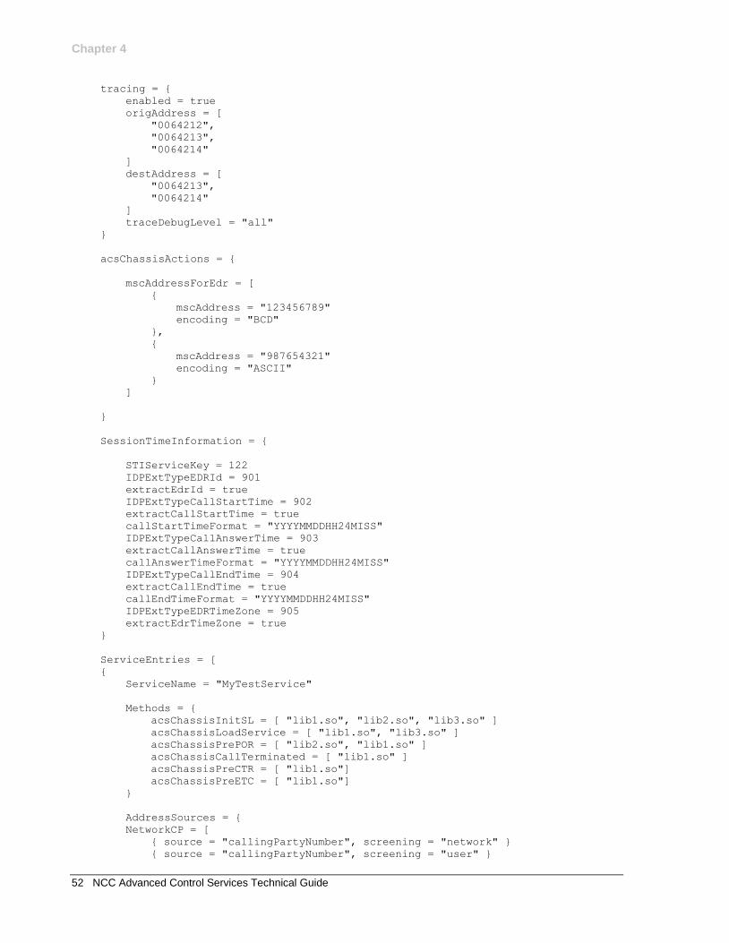
Chapter 4
52 NCC Advanced Control Services Technical Guide
tracing = {
enabled = true
origAddress = [
"0064212",
"0064213",
"0064214"
]
destAddress = [
"0064213",
"0064214"
]
traceDebugLevel = "all"
}
acsChassisActions = {
mscAddressForEdr = [
{
mscAddress = "123456789"
encoding = "BCD"
},
{
mscAddress = "987654321"
encoding = "ASCII"
}
]
}
SessionTimeInformation = {
STIServiceKey = 122
IDPExtTypeEDRId = 901
extractEdrId = true
IDPExtTypeCallStartTime = 902
extractCallStartTime = true
callStartTimeFormat = "YYYYMMDDHH24MISS"
IDPExtTypeCallAnswerTime = 903
extractCallAnswerTime = true
callAnswerTimeFormat = "YYYYMMDDHH24MISS"
IDPExtTypeCallEndTime = 904
extractCallEndTime = true
callEndTimeFormat = "YYYYMMDDHH24MISS"
IDPExtTypeEDRTimeZone = 905
extractEdrTimeZone = true
}
ServiceEntries = [
{
ServiceName = "MyTestService"
Methods = {
acsChassisInitSL = [ "lib1.so", "lib2.so", "lib3.so" ]
acsChassisLoadService = [ "lib1.so", "lib3.so" ]
acsChassisPrePOR = [ "lib2.so", "lib1.so" ]
acsChassisCallTerminated = [ "lib1.so" ]
acsChassisPreCTR = [ "lib1.so"]
acsChassisPreETC = [ "lib1.so"]
}
AddressSources = {
NetworkCP = [
{ source = "callingPartyNumber", screening = "network" }
{ source = "callingPartyNumber", screening = "user" }
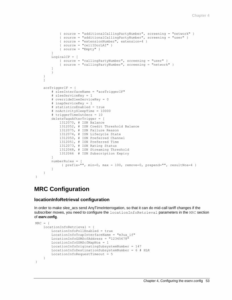
Chapter 4
Chapter 4, Configuring the eserv.config 53
{ source = "additionalCallingPartyNumber", screening = "network" }
{ source = "additionalCallingPartyNumber", screening = "user" }
{ source = "extensionNumber", extension=4 }
{ source = "cellIDorLAI" }
{ source = "Empty" }
]
LogicalCP = [
{ source = "callingPartyNumber", screening = "user" }
{ source = "callingPartyNumber", screening = "network" }
]
}
}
]
acsTriggerIF = {
# sleeInterfaceName = "acsTriggerIF"
# sleeServiceKey = 1
# overrideSleeServiceKey = 0
# inapServiceKey = 1
# statisticsEnabled = true
# noActivitySleepTime = 10000
# triggerTimeOutSecs = 10
deleteTagsAfterTrigger = [
1312070, # ISN Balance
1312052, # ISN Credit Threshold Balance
1312075, # ISN Failure Reason
1312074, # ISN Lifecycle State
1312050, # ISN Preferred Channel
1312051, # ISN Preferred Time
1312073, # ISN Rating Status
1312068, # ISN Streaming Threshold
1312066 # ISN Subscription Expiry
]
numberRules = [
{ prefix="", min=0, max = 100, remove=0, prepend="", resultNoa=4 }
]
}
}
MRC Configuration
locationInfoRetrieval configuration
In order to make slee_acs send AnyTimeInterrogation, so that it can do mid-call tariff changes if the
subscriber moves, you need to configure the locationInfoRetrieval parameters in the MRC section
of eserv.config.
MRC = {
locationInfoRetrieval = {
LocationInfoPollEnabled = true
LocationInfoTcapInterfaceName = "m3ua_if"
LocationInfoGSMScfAddress = "12345678"
LocationInfoGSMScfMapNoa = 1
LocationInfoOriginatingSubsystemNumber = 147
LocationInfoDestinationSubsystemNumber = 6 # HLR
LocationInfoRequestTimeout = 5
}
}
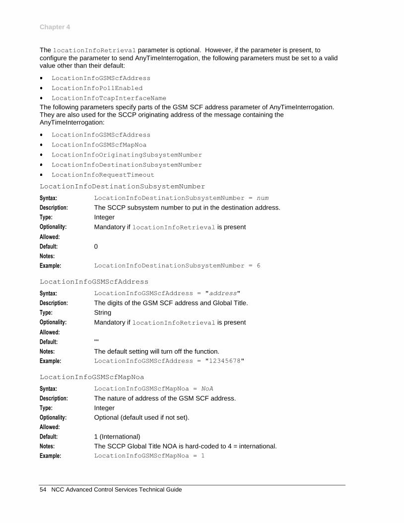
Chapter 4
54 NCC Advanced Control Services Technical Guide
The locationInfoRetrieval parameter is optional. However, if the parameter is present, to
configure the parameter to send AnyTimeInterrogation, the following parameters must be set to a valid value other than their default:
LocationInfoGSMScfAddress
LocationInfoPollEnabled
LocationInfoTcapInterfaceName
The following parameters specify parts of the GSM SCF address parameter of AnyTimeInterrogation. They are also used for the SCCP originating address of the message containing the AnyTimeInterrogation:
LocationInfoGSMScfAddress
LocationInfoGSMScfMapNoa
LocationInfoOriginatingSubsystemNumber
LocationInfoDestinationSubsystemNumber
LocationInfoRequestTimeout
LocationInfoDestinationSubsystemNumber
Syntax: LocationInfoDestinationSubsystemNumber = num
Description: The SCCP subsystem number to put in the destination address.
Type: Integer
Optionality: Mandatory if locationInfoRetrieval is present
Allowed:
Default: 0
Notes:
Example: LocationInfoDestinationSubsystemNumber = 6
LocationInfoGSMScfAddress
Syntax: LocationInfoGSMScfAddress = "address"
Description: The digits of the GSM SCF address and Global Title.
Type: String
Optionality: Mandatory if locationInfoRetrieval is present
Allowed:
Default: ""
Notes: The default setting will turn off the function.
Example: LocationInfoGSMScfAddress = "12345678"
LocationInfoGSMScfMapNoa
Syntax: LocationInfoGSMScfMapNoa = NoA
Description: The nature of address of the GSM SCF address.
Type: Integer
Optionality: Optional (default used if not set).
Allowed:
Default: 1 (International)
Notes: The SCCP Global Title NOA is hard-coded to 4 = international.
Example: LocationInfoGSMScfMapNoa = 1
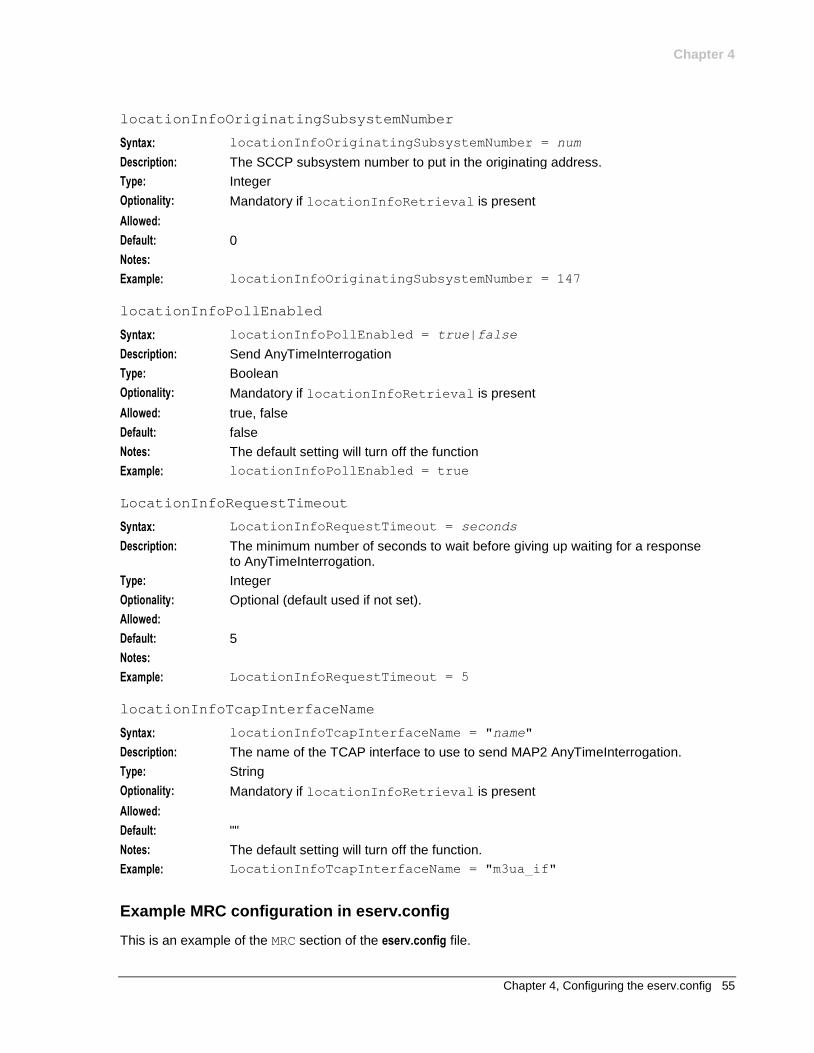
Chapter 4
Chapter 4, Configuring the eserv.config 55
locationInfoOriginatingSubsystemNumber
Syntax: locationInfoOriginatingSubsystemNumber = num
Description: The SCCP subsystem number to put in the originating address.
Type: Integer
Optionality: Mandatory if locationInfoRetrieval is present
Allowed:
Default: 0
Notes:
Example: locationInfoOriginatingSubsystemNumber = 147
locationInfoPollEnabled
Syntax: locationInfoPollEnabled = true|false
Description: Send AnyTimeInterrogation
Type: Boolean
Optionality: Mandatory if locationInfoRetrieval is present
Allowed: true, false
Default: false
Notes: The default setting will turn off the function
Example: locationInfoPollEnabled = true
LocationInfoRequestTimeout
Syntax: LocationInfoRequestTimeout = seconds
Description: The minimum number of seconds to wait before giving up waiting for a response to AnyTimeInterrogation.
Type: Integer
Optionality: Optional (default used if not set).
Allowed:
Default: 5
Notes:
Example: LocationInfoRequestTimeout = 5
locationInfoTcapInterfaceName
Syntax: locationInfoTcapInterfaceName = "name"
Description: The name of the TCAP interface to use to send MAP2 AnyTimeInterrogation.
Type: String
Optionality: Mandatory if locationInfoRetrieval is present
Allowed:
Default: ""
Notes: The default setting will turn off the function.
Example: LocationInfoTcapInterfaceName = "m3ua_if"
Example MRC configuration in eserv.config
This is an example of the MRC section of the eserv.config file.

Chapter 4
56 NCC Advanced Control Services Technical Guide
MRC = {
locationInfoRetrieval = {
LocationInfoPollEnabled = true
LocationInfoTcapInterfaceName = "m3ua_if"
LocationInfoGSMScfAddress = "12345678"
LocationInfoGSMScfMapNoa = 1
LocationInfoOriginatingSubsystemNumber = 147
LocationInfoDestinationSubsystemNumber = 6 # HLR
LocationInfoRequestTimeout = 5
}
}
Chapter 5, Configuring the acs.conf 57
Chapter 5
Configuring the acs.conf
Overview
Introduction
This chapter explains how to configure acs.conf.
In this chapter
This chapter contains the following topics.
acs.conf 57 acsChassis Plug-ins 59 acsStatisticsDBInserter (SMS) 62 acsCompilerDaemon (SMS) 64 acsStatsMaster (SLC) 66 acsChassis Single Instance Parameters (SLC) 68 acsStatsLocal (SLC) 92 acsChassis Emergency Numbers (SLC) 92 acsChassis INAP Extension Parameters 93 acsChassis Normalization Parameters (SLC) 96 acsChassis SLEE Event Size Parameter (SLC) 101 acsChassis ServiceEntry Configuration (SLC) 102 acsChassis SRF Configuration (SLC) 110 acsChassis SCF Configuration (SLC) 113 acsChassis SSF Configuration (SLC) 117 acsChassis EDR Configuration (SLC) 122 acsChassis Service Library Configuration (SLC) 131 acsChassis Service Normalisation Parameters (SLC) 132 acsChassis AWOL Configuration 132 Get Hunting Number Node Configuration 135 Play Variable Part Announcement Node Configuration 135 Number Matching Node Configuration 136 acs.conf Example 137
acs.conf
Introduction
The ACS tools and processes depend on the ACS configuration file, acs.conf (located in /IN/service_packages/ACS/etc/). There is an acs.conf file on the SMS and each SLC. The configuration options on the SMS are different to the configuration options on the SLC.
When ACS is fully installed there may be other configuration options that are added to acs.conf which are not explained in this section. Any configuration options not described in this section are required by the application and should not be changed by the user.
Chapter 5
58 NCC Advanced Control Services Technical Guide
The configuration file consists of several sections named for the executable they control. Each section contains a parameter representing a single configuration option. Leading ‘#’ characters represent comments and are ignored by the system. Each section must be terminated by a ‘:’ character. All configuration options (except those for section headers such as 'acsChassis') must be indented or they will be ignored.
Note: The acsChassis section is much larger than the other executables. Consequently the section
has been subdivided within this document.
Example configuration sections
Here are examples of configuration sections.
Example 1
Here is an example of a configuration section for the acsStatsMaster executable.
acsStatsMaster
port 1490
shmKey 17170588
semKey 17170589
masterStatsServer tcprodscp:
Example 2
Here is an example of a configuration section for the ACS_outgoing service.
ACS_outgoing
NormalUseHex 1
NormalisationRule (2,-,0,32)
NormalisationRule (2,0,1,32)
NormalisationRule (2,00,2,32)
DenormalisationRule (2,2,1,-)
DenormalisationRule (3,3,1,-)
DenormalisationRule (4,4,1,-):
Implementing parameter changes
If acs.conf is changed by the operator the service needs to be restarted, so that the configuration file is reread and the changes take effect. For more information about restarting the service see Managing Processes.
Parameter types
There are three types of parameters listed within the following topics:
1 Parameters that are a standard part of acs.conf and must be configured with the correct setting.
2 Parameters that are a standard part of acs.conf with default settings and do not require configuring except in the case of custom settings for a specific site.
3 Parameters that must be added to acs.conf with the correct setting.
Note: Some parameters appear only once within the following topics (for example, port). Other
parameters may appear multiple times (for example, ServiceEntry).
Before you begin
Most values in acs.conf are set to sensible defaults. Be sure to read the relevant information in the following sections before modifying these values.
It is recommended that you make a backup copy of acs.conf before altering the service settings.
Chapter 5
Chapter 5, Configuring the acs.conf 59
Procedure
Edit the acs.conf file with any UNIX text editor.
Example command: vi acs.conf
acsChassis Plug-ins
acsChassis
The acsChassis configuration defines details about how traffic coming in to slee_acs is handled. It defines what traffic is processed by which service on what service loader plug-in library. It also provides some additional configuration about how slee_acs will process the traffic to each service.
The available parameters are:
ServiceEntry
Syntax: ServiceEntry (service,service_library)
Description: The ServiceEntry lines are needed to define which services defined in the SLEE.cfg are handled by the CCS service loader library (ccsSvcLibrary).
Type:
Optionality: Mandatory (must be set to include the required CCS library).
Allowed: For more information about the structure of this configuration option, see acsChassis ServiceEntry Configuration (SLC) (on page 102). For more information about the values which can be used in the service element of this configuration, see the technical guide for the relevant service.
Default:
Notes: Any service defined in SLEE.cfg must have a corresponding ServiceEntry line
configured in acs.conf.
Example: ServiceEntry (CCS,ccsSvcLibrary.so)
ServiceEntry (EAX_MO,libeaxSvcLibrary.so)
MacroNodePluginFile
Syntax:
Description: The MacroNodePluginFile lines are required to define which feature node libraries will be available in the control plans used by slee_acs. The CCS feature node library (ccsMacroNodes) must be included here.
Type:
Optionality: Mandatory (must be set to include the required CCS library).
Allowed:
Default:
Notes: Some plug-in-based feature nodes distributed with CCS are:
Attempt Termination with Billing node
Language Select node
Voucher Recharge node
Example: MacroNodePluginFile ccsMacroNodes.so
Chapter 5
60 NCC Advanced Control Services Technical Guide
ChassisPlugin
Syntax:
Description: Chassis plug-ins provide the ACS Control Plan Editor with an expanded interface to its environment.
The ChassisPlugin lines are required to define which chassis action libraries will be available to slee_acs. The CCS chassis action library (ccsActions) must be included here.
Type:
Optionality: Mandatory (must be set to include the required CCS library).
Allowed:
Default:
Notes: The interface between the CPE and the Voucher and Wallet Server is implemented using chassis plug-ins. Other uses include external database operations or network access.
One shared library may implement more than one chassis action.
No further configuration is needed to allow the Chassis to load the plug-ins at startup. However, individual plug-ins may have configuration requirements of their own.
For more information about the slee_acs, see ACS Technical Guide.
Example: acsChassis ChassisPlugin ccsActions.so
srf
Syntax:
Description: The name and number of the Specialized Resource Function (or Intelligent Peripheral) is required for each IP on the network.
Type:
Optionality:
Allowed: (srfName, UseETC=Y|N, Address=IP or nothing, NOA=0-4 typeOfSrf=NAP or other)
Default:
Notes: Parsing should continue until no new IPs can be found in the configuration file. This will eliminate the need for a count to be specified in the configuration file for the number of resources available.
Example: srf (nap1,UseETC=N,Address=,NOA=3)
acsChassis plugin libraries
Both parts of slee_acs (the acsChassis and the acsEngine) can be extended to do new tasks by installing plug-in libraries (independent pieces of program code that are loaded into the system at runtime).
Plug-ins are distributed as shared libraries with the file extension of .so.
slee_acs must be informed of the location of these shared libraries, so that their functionality can be made available to the running system.
Plug-in shared libraries may be stored anywhere in the file system. However, the recommended location for plug-ins is:
/IN/service_packages/package_name/lib
Chapter 5
Chapter 5, Configuring the acs.conf 61
Note: If plug-ins are not specified in acs.conf as an absolute path to the shared library, shared libraries are searched for in the path read from the environment variable LD_LIBRARY_PATH. The location recommended above is listed in the search path by default after installation.
Initialization
The ACS ChassisEngine program will always load Engine plug-ins after fully loading and initializing all Chassis plug-ins, regardless of the order of configuration lines in acs.conf.
This is done to ensure that plug-in-based chassis actions are always available to plug-in-based engine nodes as they load and initialize themselves.
Note: All configured Chassis and Engine plug-ins are loaded and initialized in order of appearance in acs.conf within their own class of plug-in.
Plug-in list
The following plug-ins are required by the acsChassis:
MacroNodePluginFile
Syntax: MacroNodePluginFile = lib
Description: These lines configure which feature node libraries are available to slee_acs. This may be as simple as just the ACS feature node library (libacsMacroNodes (on page 153)) which provides the base ACS feature nodes, but may also include other libraries provided by other components.
Type: String
Optionality: Optional (no libraries loaded if not set).
Allowed:
Default: None
Notes: Individual plug-ins may have additional configuration requirements of their own, not detailed here.
One shared library may implement more than one feature node.
Engine plug-ins must be configured with entries in the following database tables: 1 ACS_FN_TYPE
2 ACS_FN_STRUCT_DEF
3 ACS_FN_DATA_DEF
The database is configured appropriately on installation, and should not need updating.
Example: MacroNodePluginFile = libacsMacroNodes
ChassisPlugin
Syntax: ChassisPlugin = lib
Description: Pluggable Action - base ACS actions.
These lines configure which chassis action libraries are available to slee_acs. This may be as simple as just the ACS chassis action library (libacsChassisActions (on page 153)), but may also include other libraries provided by other components.
Type: String
Optionality: Optional (no libraries loaded if not set).
Allowed:
Default: None
Notes: Individual plug-ins may have additional configuration requirements of their own,
Chapter 5
62 NCC Advanced Control Services Technical Guide
not detailed here.
One shared library may implement more than one feature node.
Example: ChassisPlugin = libacsChassisActions
srf
Syntax: For a full syntax, see acsChassis SRF Configuration (SLC) (on page 110).
Description: Specialized Resource Function mappings for the SLEE.
Type: String
Optionality: Optional (default used if not set).
Allowed:
Default: (NAP1, UseETC=N, Address=, NOA=3)
Notes:
Example:
acsStatisticsDBInserter (SMS)
Introduction
The acsStatisticsDBInserter must know the name and port number of the acsStatsMaster. Because this process also inserts data into the database it is also possible to change the default username and password in the acs.conf file.
Therefore the acsStatisticsDBInserter section within acs.conf on the SMS must be populated to specify the name of the machine and the port number used by the acsStatsMaster.
Parameters
The parameter below must be configured with the correct value;
oracleusername
Syntax: oracleusername user
Description: The user name acsStatisticsDBInserter will use to connect to Oracle.
Type: String
Optionality: Optional (default used if not set)
Allowed:
Default: null
Notes: If no oracleusername and oraclepassword are specified, the string used to
connect to Oracle is "/". This is the recommended way to connect to Oracle. For more information, see Oracle usr/pwd string (on page 20).
Example:
oraclepassword
Syntax: oraclepassword password
Description: The password acsStatisticsDBInserter should use to connect to Oracle.
Type: String
Optionality: Optional (default used if not set)
Allowed:
Default: null
Chapter 5
Chapter 5, Configuring the acs.conf 63
Notes: If the default is used, the actual string used to connect to Oracle will use the password for the account which is running acsStatisticsDBInserter. This should be the acs_oper account's password.
Example:
MasterServerPort
Syntax: MasterServerPort port
Description: The port on which the master statistics server is listening for requests.
Type: Integer
Optionality: Optional (default used if not set)
Allowed: Any integer representing a valid port address
Default: null
Notes:
Example:
Retries
Syntax: Retries int
Description: The number of attempts to make to communicate with the statistics master server before failing.
Type: Integer
Optionality: Optional (default used if not set)
Allowed: Any non zero, positive integer.
Default: 3
Notes:
Example:
Period
Syntax: Period seconds
Description: The number of seconds between queries of the statistics master server.
Type: Integer
Optionality: Optional (default used if not set)
Allowed: Any non zero, positive integer.
Default: 30
Notes:
Example:
MasterServerLocation
Syntax: MasterServerLocation name
Description: The system name of the master statistics server.
Type: String
Optionality: Optional (default used if not set)
Allowed:
Default: SCP1
Notes: Any string representing the system name required.
Example:
Chapter 5
64 NCC Advanced Control Services Technical Guide
acsCompilerDaemon (SMS)
Introduction
The acsCompilerDaemon process is responsible for converting a control plan into the binary format used by the ACS service logic to process calls.
Parameters
The parameters in this list assume the default values if they are not configured. Only one entry per parameter is allowed.
oracleusername
Syntax: oracleusername user
Description: The user name acsCompilerDaemon should use to connect to Oracle.
Type: String
Optionality: Optional (default used if not set)
Allowed:
Default: null
Notes: If the default is used, the actual string used to connect to Oracle will use the account which is running acsCompilerDaemon. This should be acs_oper account.
Example:
oraclepassword
Syntax: oraclepassword password
Description: The password acsCompilerDaemon should use to connect to Oracle.
Type: String
Optionality: Optional (default used if not set)
Allowed:
Default: null
Notes: If the default is used, the actual string used to connect to Oracle will use the password for the account which is running acsCompilerDaemon. This should be the acs_oper account's password.
Example:
alertTimeout
Syntax: alertTimeout secs
Description: The number of seconds to remain blocked waiting for the alert to occur before checking for signals.
Type: Integer
Optionality: Optional (default used if not set).
Allowed: Any non zero, positive integer.
Default: 5
Notes: Since signals are blocked for this period of time, it is recommended that this number is not increased beyond 5 because it may cause the process to not terminate correctly on system shutdown.
Example:
Chapter 5
Chapter 5, Configuring the acs.conf 65
maxBranches
Syntax: maxBranches int
Description: The maximum number of branches any feature node in a control plan may have.
Type: Integer
Optionality: Optional (default used if not set)
Allowed: Any non zero integer.
Default: 99
Notes: If this is set to lower than 99, users must ensure they do not set any of the feature nodes in their control plans to more than maxBranches. If they do, their control plan will not compile.
Example: maxBranches 99
maxNodes
Syntax: maxNodes int
Description: The maximum number of nodes any control plan may have.
Type: Integer
Optionality: Optional (default used if not set).
Allowed: Any non zero, positive integer.
Default: 100
Notes: To determine the number of nodes in a control plan, the control plan must be opened in the CPE. The properties for the control plan will give the number of nodes used.
Example:
maxCompiledKb
Syntax: maxCompiledKb int
Description: Max size of the binary produced when a control plan is compiled.
Type: Integer
Optionality: Optional (default used if not set).
Allowed: Any integers in range 1 - 256.
Default: 64
Notes: Setting above the default value may not be supported by replication, please check with support before increasing this limit.
Example:
compressAtKb
Syntax: compressAtKb Kb
Description: The maximum size in Kilobytes of a control plan, before acsCompilerDaemon will compress it when it compiles it.
acsCompilerDaemon compresses control plans before checking whether they exceed maxCompiledKb.
Type: Integer
Optionality: Optional (default used if not set).
Allowed: Any non zero, positive integer.
Default: 64
Notes: To be effective, this parameter should be set lower than maxCompiledKb (on page
Chapter 5
66 NCC Advanced Control Services Technical Guide
65), any changes require the acsCompilerDaemon to be restarted for any changes to take effect.
Example:
compressLevel
Syntax: compressLevel int
Description: The level of compression used in control plan compression if compressAtKb (on page 65) is exceeded.
Type: Integer
Optionality: Optional (default used if not set).
Allowed: 0 No compression.
1-9 Compression level, where 1 is low and 9 is high.
Default: 0
Notes: Any changes require the acsCompilerDaemon to be restarted for any changes to take effect.
Example:
endUnlinkedExits
Syntax: endUnlinkedExits 0|1
Description: Allow unconnected exits from a feature node in a control plan.The control plan must contain at least one End feature node.
Type: Boolean
Optionality: Optional (default used if not set)
Allowed: 0 – Do not allow unconnected feature node exits.
1 – Connect all unconnected exits to the first End feature node in the control plan when the control plan is saved.
Default: 0
Example: endUnlinkedExits 1
AuditChallenge
Description: Because acsCompilerDaemon runs on the SMS, AuditChallenge should be
set to 1 for acsCompilerDaemon. This parameter should be disabled for
processes that run on the VWS, or SLC.
Default: 0
Allowed: 0 (disabled), 1 (enabled)
Example: AuditChallenge 1
acsStatsMaster (SLC)
Introduction
This process is the single point of statistics access for other systems in the network. It processes requests for other SLCs as well as the SMS.
Parameters
The following parameters must be configured with the correct value.
Chapter 5
Chapter 5, Configuring the acs.conf 67
oracleusername
Syntax: oracleusername user
Description: The user name acsStatsMaster should use to connect to Oracle.
Type: String
Optionality: Optional (default used if not set)
Allowed:
Default: null
Notes: If the default is used, the actual string used to connect to Oracle will use the account which is running acsStatsMaster. This should be acs_oper account.
Example:
oraclepassword
Syntax: oraclepassword password
Description: The password acsStatsMaster should use to connect to Oracle.
Type: String
Optionality: Optional (default used if not set)
Allowed:
Default: null
Notes: If the default is used, the actual string used to connect to Oracle will use the password for the account which is running acsStatsMaster. This should be the acs_oper account's password.
Example:
masterStatsServer
Description: Host name of the machine running the master stats server.
Default: No default
Allowed: Any string representing a valid host name.
port
Description: Port on which the stats master listens for connection attempts.
Default: 1490
Allowed: Any integer that represents a valid port address.
shmKey
Description: Shared Memory key for the acsStatsMaster.
Default: 17170588
Allowed: acsChassis shmKey value.
Notes: This must be the same as the entry for the acsChassis shmKey.
It is recommended that the user does not change this value unless there is a collision. It is up to the installer to ensure that there are no collisions.
semKey
Description: Semaphore Key for acsStatsMaster.
Default: 17170589
Allowed: acsChassis semKey value.
Chapter 5
68 NCC Advanced Control Services Technical Guide
Notes: This must be the same as the entry for the acsChassis semKey.
It is recommended that the user does not change this value unless there is a collision. It is up to the installer to ensure that there are no collisions.
acsChassis Single Instance Parameters (SLC)
Parameters
The following parameters must be configured with the correct value.
masterStatsServer
Description: Host name of the machine running the master stats server.
Default: No default
Allowed: Any string representing a host name, but must be the same as the
masterStatsServer of the acsStatsLocal section. For example
scp1.telconame.com
port
Description: Port on which the stats master listens for connection attempts.
Default: 1490
Allowed: Any valid integer representing a port address.
shmKey
Description: Shared Memory key for the acsStatsMaster.
Default: 17170588
Allowed: Must be the same as acsStatsMaster shmKey.
semKey
Description: Semaphore Key for acsStatsMaster.
Default: 17170589
Allowed: Must be the same as the acsStatsMaster semKey.
addChargingInfoToCTR
Description: Perform FCI/SCI for CTR
Default: 0 (false)
Allowed: 0 or 1 (true)
addChargingInfoToETC
Description: Perform FCI/SCI for ETC
Default: 0
Allowed: 0 (false) or 1 (true)
addChargingInfoToPA
Syntax: addChargingInfoToPA 0|1
Description: Perform FCI/SCI for PA and PACUI.
Type: Boolean
Chapter 5
Chapter 5, Configuring the acs.conf 69
Optionality: Optional (default used if not set).
Allowed: 0 (false), do not perform FCI/SCI
1 (true), do perform FCI/SCI
Default: 0
Notes:
Example: addChargingInfoToPA 1
DigitsInAnnouncementList
Syntax: DigitsInAnnouncementList 0|1
Description: If set to true, records the details of any interaction between the caller and the control plan in the AIDL EDR tag.
Type: Boolean
Optionality: Optional (Default is used if omitted)
Allowed: 0 (off), 1 (on)
Default: 0
Notes: Refer to AIDL for a description of changes to the AIDL information.
Example: DigitsInAnnouncementList 1
AddMOLIPrefix
Description: Specifies a numeric prefix to the three character MOLI code that is placed into
the calling network address field (see CheckMOLIPrefix (on page 73)).
Optionality: Optional, and does not need to be provided whenever a CheckMOLIPrefix
parameter is included in the acs.conf file.
Default: 222
Allowed: 1 to 20 numeric characters can be specified.
Notes: See Section 6.2 of the ACIF document G532 for more details on the MOLI standard.
alwaysIncludePartyToCharge
Syntax: alwaysIncludePartyToCharge value
Description: Whether to set the partyToCharge parameter in ACS to the leg1 party or not.
Type: Integer
Optionality: Optional (default used if not set).
Allowed: Any integer value. However any value other than 1 is treated as 0.
Default: 0
Notes: 0 - partyToCharge is not set.
1 - partyToCharge is set.
Example: alwaysIncludePartyToCharge 1
alternativeCallPlanNamePostfix
Syntax: alternativeCallPlanNamePostfix _name
Description: This string is appended to the end of the control plan name creating a new plan. This is the replacement plan when alternative control plan replacement is activated from the ACS Screen:
Services -> ACS Service -> Customer -> Control Plan Change tab
Chapter 5
70 NCC Advanced Control Services Technical Guide
Type: String
Optionality: Optional (default used if not set).
Allowed:
Default: _alt
Notes:
Example: alternativeCallPlanNamePostfix _emergency
armDisconnectAt
Syntax: armDisconnectAt 0|1
Description: Forces the AT feature node to arm for oDisconnect in the associated BCSM Event when set to true.
Type: Boolean
Optionality: Optional (default used if not set).
Allowed: 0 (false), do not arm for oDisconnect
1 (true), arm for oDisconnect
Default: 0
Notes:
Example: armDisconnectAt 1
armDisconnectAtp
Syntax: armDisconnectAtp 0|1
Description: Forces the ATP feature node to arm for oDisconnect in the BCSM Event when set to true.
Type: Boolean
Optionality: Optional (default used if not set).
Allowed: 0 (false), do not arm for oDisconnect
1 (true), arm for oDisconnect
Default: 0 - false
Notes:
Example: armDisconnectAtp 1
armDisconnectLeg1
Description: On disconnect requests, do we include Leg1 disconnects.
Default: 1
Allowed: 0 (false), 1 (true)
armDisconnectLeg2
Description: On disconnect requests, do we include Leg2 disconnects.
Default: 1
Allowed: 0 (false),1 (true)
armLegsSeparately
Description: Produces two BCSM Event Reports; one for Leg1 and one for Leg2.
Default: 1
Allowed: 0 (disabled), 1 (enabled)
Chapter 5
Chapter 5, Configuring the acs.conf 71
ArmTerminateTriggers
Default: 0
Allowed: 0 = Only use originating ('o') type EDPs
1 = Enable arming of originating ('o') and terminating ('t') type EDPs
AssumePreArrangedEnd
Description: Enables the logic in slee_acs that handles prearranged TCAP ends. This ensures the clean shut down of the call dialog and all related events.
Default: 0
Allowed: 0 (disabled), 1 (enabled)
Notes: This may be useful in cases where dialogs and events are leaking, yet the system appears to be operating normally.
atDisconnectMM_Leg1Interrupt
Description: Should arm disconnect on Leg1 as
Default: 0
Allowed: 0 (notify), 1 (interrupt)
atDisconnectMM_Leg2Interrupt
Description: Should arm disconnect on Leg2 as
Default: 1
Allowed: 0 (notify), 1 (interrupt)
AuditChallenge
Description: This should not be required to be set in an operational environment. Set this parameter to 0 (zero) unless running on an SMS.
Default: 0
Allowed: 0 (disabled), 1 (enabled)
Example: AuditChallenge 0
CallInitiationExtensionForIdp
Syntax: CallInitiationExtensionForIdp = int
Description: Determines whether the call initiation node should place the SLEE call ID in the configured extension.
Type: Integer
Optionality: Optional
Allowed:
Default:
Notes: The CallInitiationExtensionForIdp and extensionNumber (on page
95) configuration parameters in acs.conf can be used to correlate EDRs generated from two calls that involve the Call Initiation node.
Example: CallInitiationExtensionForIdp = 123
Chapter 5
72 NCC Advanced Control Services Technical Guide
CallInitiationTimeoutToleranceSeconds
Description: This parameter is for use with the Call Initiation node (CIN).
Default: 10
Allowed: Maximum 0xFFFF (18 hours)
Notes: This value is added to the No Answer timeout value in the CIN to set an overall tolerance timer in the outgoing TCAP interface. When the sum of these two values is reached the TCAP interface will send a TCAP_CANCEL back to ACS to defend against the event of lost responses from the SSF.
CallInitiationUseContextInd
Syntax: CallInitiationUseContextInd value
Description: Defines whether the indicator values are obtained from the call context buffer (so can be set through the Set Indicator node or denormalization rules) or are fixed.
Type: Integer
Optionality: Optional (default used if not set).
Allowed: 0, 1, 2, 3
Default: 0
Notes: 0=All indicator values, including NoA, set to the original values (NoA = 4, ScrnInd = 3, PresInd = 0, NumIncomplete = 0).
1=All indicator values, except NoA, set to original values. The NoA value would come from the context and could be altered using denormalization rules.
2=NoA set to original value. Other indicator values come from context and could be altered through Set Indicator nodes in the control plan.
3=All indicator values would come from the context. The NoA value could be altered through denormalization rules and the other indicator values could be altered through Set Indicator nodes in the call plan.
In all cases the NumberPlan will be set to 1.
Example: CallInitiationUseContextInd 2
CalledPartyBcdToNoaMap
Syntax: CalledPartyBcdToNoaMap = "0,1,2,3,4,5,6,7"
Description: Used to convert MAP nature of address (NOA) indicators, such as CAMEL BCD, to the ISUP standard used by ACS for internal NOA values.
Type: Array
Optionality: Optional (default used if not set).
Allowed: This array uses the position in the array (starting at 0) to determine the MAP NOA to match, and the value to determine the ISUP NOA to translate to.
Default: 2,4,3,5,1,0,0,0
That is, change MAP to ISUP as follows:
MAP NOA ISUP NOA
0 (unknown) 2 (unknown)
1 (international) 4 (international)
2 (national) 3 (national)
3 (network-specific) 5 (network-specific)
4 (subscriber) 1 (subscriber)
5, 6, 7 0 (unknown)
Notes:
Chapter 5
Chapter 5, Configuring the acs.conf 73
Example: CalledPartyBcdToNoaMap = "2,4,2,5,1,0,0,0"
callProcessingAllowedAfterAPartyDisconnect
Syntax: callProcessingAllowedAfterAPartyDisconnect 0|1
Description: Whether or not to allow call processing after the A party has hung up.
Type: Boolean
Optionality: Optional (default used if not set).
Allowed: 0, 1
Default: 0 (not allowed)
Notes: Setting this parameter to 1 leaves call processing set to true on receipt of TC_CONTINUE(ERBCSM(oDisconnect,Leg1,Interrupted))
Example: callProcessingAllowedAfterAPartyDisconnect 1
CancelChar
Description: The character used by the user to cancel the previously entered digits.
Default: B (Hex value)
Allowed: Entry char and cancel char may be specified as hex digits or * or #. However, # must be entered as \# to stop it being interpreted as a comment.
CarrierCodeDisposal
Syntax: CarrierCodeDisposal 0|1
Description: How the carrier code call context variable is handled in outgoing connect operations.
Type: Boolean
Optionality: Optional, default used if not set.
Allowed: 0 The carrier code is prefixed to the termination number.
1 The Termination number is not modified. This effectively nullifies the function of any Set Carrier Code feature node.
Default: 0
Notes:
Example: CarrierCodeDisposal 0
ChainCountLimit
Description: This limits the number of times the control plan is allowed to chain to other ACS services during a single call.
Default: 8
Allowed: Any non-zero positive integer.
Notes: The digit entered indicates the number of ServiceHandovers possible in a single call.
This is most important in VPN, where it stops station-forwarding loops.
CheckMOLIPrefix
Description: This specifies the prefix on a dialed number that identifies it as containing MOLI (Mobile Location Indicator) information.
Default: 029
Chapter 5
74 NCC Advanced Control Services Technical Guide
Allowed: Only a single prefix is supported, with a length of 1 to 20 characters.
Notes: If a called number has the prefix specified, the ACS chassis will remove the prefix and apply MOLI decoding rules. This places the three digit MOLI code from the number into the calling network address field.
CollectInfoReturnsAll
Description: When sending an RRB+CI, (Request Report BCSMEvent and Collect Information) though the service asks for 1 digit at a time, the SSP will always send 'previously sent DN+the extra digit'.
Default: 0
Allowed: 0 (false), 1 (true)
Notes: The ETSI INAP specification is unclear as to whether the return result should be all the digits collected thus far, or just the most recent digit.
This configuration option enables you to specify what behavior to expect.
CopySpareBits
Description: slee_acs copies the following data from the indicated source:
Presentation restricted and screening indicators from called party number
INN and screening indicator from original called party number
Default: 0
Allowed: 0 (copies the data from the relevant parameter in the Initial DP on the grounds that they are defined as spare in the ETSI standards)
1 (copies from elsewhere)
dfcOnIpAbort
Description: Should we Dfc to the SSP when the IP dialog is doored.
Default: 0
Allowed: 0 (no), 1 (yes)
DialledHashEncoding
Description: Enter the network encoding for # in BCD.
Default: C (Hex value)
Allowed:
DialledStarEncoding
Description: Enter the network encoding for * in BCD.
Default: B (Hex value)
Allowed:
dialogTickInterval
Syntax: dialogTickInterval interval
Description: The time during which dialog timers are checked.
Type: Integer
Units: Seconds
Optionality: Optional
Allowed: interval 0
Chapter 5
Chapter 5, Configuring the acs.conf 75
Default: The dialogTickInterval parameter is omitted.
Notes: If the dialogTickInterval parameter is omitted, the SLEE sets to 10
the time during which dialog timers are checked.
If interval = 0, the SLEE sets to 10 the time during which dialog timers
are checked.
If interval > 0, interval is the time during which dialog timers are
checked.
Example: dialogTickInterval 15
disarmEDPs
Description: How to handle EDPs which may still be armed on the SSP.
Default: 1
Allowed: 0 = Never disarm oAbandon (assume switch always disarms)
1 = Always explicitly dis-arm and re-arm for a subsequent connect.
2 = If oAbandon is still armed, and a subsequent connect wants it armed, then do nothing. If the subsequent connect does not want it armed, then explicitly clear it.
DisconnectMidCallJumpBack
Description: Should a Disconnect node instead generate a MidCallJump if there is a MidCallMark pending?
Default: 1
Allowed: 0 (no), 1 (yes)
edpArmAbandoned
Description: When an Attempt Terminate is performed in ETSI, there are a number of cases for which the switch may test, as not all switches support all cases.
Default: 0
Allowed: 0 This exit branch will never be followed from the Attempt Terminate or Follow Me nodes.
1 This exit branch will be followed.
edpArmAnswer
Description: When an Attempt Terminate is performed in ETSI, there are a number of cases for which the switch may test, as not all switches support all cases.
Default: 0
Allowed: 0 This exit branch will never be followed from the Attempt Terminate or Follow Me nodes.
1 This exit branch will be followed.
edpArmBusy
Description: When an Attempt Terminate is performed in ETSI, there are a number of cases for which the switch may test, as not all switches support all cases.
Default: 0
Allowed: 0 This exit branch will never be followed from the Attempt Terminate or Follow Me nodes.
1 This exit branch will be followed.
Chapter 5
76 NCC Advanced Control Services Technical Guide
edpArmNoAnswer
Description: When an Attempt Terminate is performed in ETSI, there are a number of cases for which the switch may test, as not all switches support all cases.
Default: 0
Allowed: 0 This exit branch will never be followed from the Attempt Terminate or Follow Me nodes.
1 This exit branch will be followed.
edpArmRouteSelectFailure
Description: When an Attempt Terminate is performed in ETSI, there are a number of cases for which the switch may test, as not all switches support all cases.
Default: 0
Allowed: 0 This exit branch will never be followed from the Attempt Terminate or Follow Me nodes.
1 This exit branch will be followed.
edpSetNoAnswerTimer
Description: Options for handling no answer.
Default: 1
Allowed: 0 = Never (never set the applicationTimer)
1 = Always (always set the applicationTimer to the requested value)
2 = Non-Zero (override only nonzero requested values to the NoAnswerTimeout value)
3 = Override (always override the requested value to the NoAnswerTimeout value)
4 = Override Zero (override the requested value to the NoAnswerTimeout value if the requested value is zero)
edpUseNoAnswerTimer
Description: This flag indicates whether to explicitly tell the switch how long to wait for NoAnswer. Some switches do not like being told, in which case we will omit the parameter and let it use a network default.
Default: 1
Allowed: 0 (disabled), 1 (enabled)
emptyDraIsError
Syntax: emptyDraIsError = true|false
Description: Determines whether to retain the original behavior of reporting an error if the normalized DRA is empty, or suppress this error.
Type: Boolean
Optionality: Optional (default used if not set).
Allowed: 1 true
0 false. This error will not be reported and the processing of the call will proceed as normal.
Default: 1
Notes:
Example: emptyDraIsError = 1
Chapter 5
Chapter 5, Configuring the acs.conf 77
EntryChar
Description: The character used to indicate the end of input.
Default: C (Hex value)
Allowed: Entry char and cancel char may be specified as hex digits or * or #. However, # must be entered as \# to stop it being interpreted as a comment.
ETC_CorrelationIdInIPAddr
Description: If on, appends the SRF correlation ID to the IP's address.
If off, uses the proper field in an ETC message for containing the SRF correlation ID.
Default:
Allowed: 0 (off), 1 (on)
ETC_MinCorrelationDigits
Description: The SRF correlation ID digits (used above) out to a fixed number of digits.
Default:
Allowed:
ETC_SCF_ID
Description: Contains the SCF ID.
If the ETC_CorrelationIdInIPAddr is 1, then the IP prefix set is appended with the correlation ID and then appended with the value of ETC_SCF_ID, if it is set in the acs.conf file.
If ETC_SCF_ID is not set in the acs.conf file, the SCF ID is not appended. If ETC_CorrelationIdInIPAddr is 0, then the SCF ID and correlation ID are sent as separate parameters in the ETC message.
Default:
Allowed: The SCF ID
extraStats
Description: Should we record extra statistics. See Extra statistics (on page 91) for the list.
Default: 0
Allowed: 0 (no), 1 (yes)
fakeAcrCallReleaseAtMaxDuration
Syntax: fakeAcrCallReleaseAtMaxDuration 0|1
Description: If this flag is set, then ACS assumes that a CAMEL phase 2 call is released with the call duration greater or equal to the maximum call duration period, and the call
is treated like a CAMEL phase 3 call with the callReleasedAtTcpExpiry
present.
Type: Boolean
Optionality: Optional (default used if not set).
Allowed: 1 (true), 0 (false)
Default: 0
Notes:
Example: fakeAcrCallReleaseAtMaxDuration 0
Chapter 5
78 NCC Advanced Control Services Technical Guide
FakeAcrCallReleaseAtTcpExpiry
Description: Using CAP2, when you receive and process an Apply Charging Report it is unclear if you should expect a subsequent EventReportBCSM (caller/called hang-up case) or not (switch force disconnect case).
Default: 0
Allowed: 0 (not set), 1 (set)
Notes: CAP3 includes the callReleaseAtTcpExpiry flag to CAP3's ACR to clarify this processing.
To enable processing to be clear while using CAP2, ACS attempts to detect the case by sniffing the primitive that contained the ACR to see if it also contains an ERBCSM.
If it does not contain an ERBCSM, it can be assumed that none is coming. To provide the ACR functions with the necessary data, we will set the callReleaseAtTcpExpiry flag on the ACR.
Example: FakeAcrCallReleaseAtTcpExpiry 0
fakeMissingAcrAtDisconnection
Syntax: fakeMissingAcrAtDisconnection 0|1
Description: When the B party hangs up and oDisconnect leg 2 is armed as interrupted, NCC expects an Apply Charging Report followed by an Event Report BCSM to be returned by the SSP.
Some SSPs only return an Event Report BCSM. In this case setting
fakeMissingAcrAtDisconnection to 1 will replicate the anticipated behavior.
Type: Boolean
Optionality: Optional (default used if not set)
Allowed: 0 (false), 1 (true)
Default: 0
Notes: In some cases, the Event Report BCSM is sent before the Apply Charging Report. This is non CAP standard behavior. In this case the parameter should be set to 0.
Example: fakeMissingAcrAtDisconnection 0
fciInSeparateMessageAllOperations
Syntax: fciInSeparateMessageAllOperations 0|1
Description: Whether or not to send the FurnishChargeInformation in a separate TCAP message, before the TCAP message is sent.
Type: Boolean
Optionality: Optional (default used if not set).
Allowed: 0, 1
Default: 0 (do not send)
Notes: This applies to all operations, not just a Connect.
Example: fciInSeparateMessageAllOperations 1
fciInSeparateMessage
Syntax: fciInSeparateMessage 0|1
Description: Whether or not to send the FurnishChargeInformation in a separate TCAP message, before the TCAP message is sent.
Type: Boolean
Optionality: Optional (default used if not set).
Chapter 5
Chapter 5, Configuring the acs.conf 79
Allowed: 0, 1
Default: 0 (do not send)
Notes: This only applies to a Connect operation.
Example: fciInSeparateMessage 1
fciMaximumLength
Description: Maximum length of FCI binary data record generated by concatenating FCI tariff codes.
Default: 200
Allowed: Integer, in the range 1-200.
fciSeparator
Description: Optional separator between concatenated FCI tariff codes.
Default: ""
Allowed:
FirstDigitTimeout
Description: This indicates the time to wait in seconds for the first digit to be entered.
Default: 4
Allowed: Any non zero, positive integer.
GlobalProfileMaxAge
Description: The maximum age, in seconds, that the global profile and global Control Plan is allowed to reach before it is reloaded from the database.
Default: 300
Allowed: Integer
Notes: The global profile and global Control Plan age is checked at the start of a call.
ignoreNumberPlanForConnectToContinue
Syntax: ignoreNumberPlanForConnectToContinue 1|0
Description: Determines whether to ignore the number plan indicator when comparing the DRA and the triggered called number while checking if a connect or continue message should be sent.
Type: Boolean
Optionality: Optional (default used if not set).
Allowed: 1 (ignore), 0 (do not ignore)
Default: 0
Notes:
Example: ignoreNumberPlanForConnectToContinue 0
InterDigitTimeout
Description: This indicates the time, in seconds, to wait for the next digit to be entered.
Default: 4
Allowed: Integer
Chapter 5
80 NCC Advanced Control Services Technical Guide
InternalErrorAction
Description: This indicates the required action if there is an unexpected internal error.
Default: disconnect
Allowed: disconnect, continue
IPProtocolInfo
Description: Use INAP to talk to Intelligent Peripherals.
Default: 1
Allowed: No other values are currently supported.
maxAnnouncementTextBytes
Syntax: maxAnnouncementTextBytes value
Description: Maximum number of bytes allowed in the text field of a PlayAnnouncement or PromptAndCollectUserInformation operation.
Type: Integer
Optionality: Optional
Allowed: Positive integer
Default: 80
Notes:
Example: maxAnnouncementTextBytes 80
MaxPromptDigits
Description: This parameter indicates the maximum number of digits to be entered.
Default: 255
Allowed:
MinZeroTimeRemainingPeriod
Description: Sets the amount of time (in seconds) for handling duplicate ACR on race condition during hang-up of secondary reservation time.
Default: 5
Allowed:
NoAnswerTimeout
Description: Time (in seconds) before a call returns No Answer.
Default: 10
Allowed: Integer
NoCallPlanAction
Description: This parameter indicates the required action if there is no control plan.
Default: continue
Allowed:
NoCallPlanCause
Description: Release cause to return to SSP if no Control Plan exists and if NoCallPlanAction is "disconnect".
Default: 1
Chapter 5
Chapter 5, Configuring the acs.conf 81
Allowed: 0 (No cause reported), 1 (Unallocated Number)
Notes: Refer to Q.850.
NoCallPlanError
Description: This indicates the severity level of the error generated.
Default: NOTICE
Allowed: NOTICE
WARNING
ERROR
CRITICAL
Notes: Errors are logged in two places:
SMS alarm system
/var/adm/messages
NoDatabaseConnectAction
Description: There is no connection to the database.
Default:
Allowed:
NoServiceAction
Description: This indicates the required action if there is no ServiceEntry in acs.conf for this Service Name.
Default: disconnect
Allowed: disconnect, continue
NoServiceError
Description: This indicates the severity level of the error generated.
Default: WARNING
Allowed: NOTICE
WARNING
ERROR
CRITICAL
Notes: Errors are logged in two places:
SMS alarm system
/var/adm/messages
OverrideDefaultIPDigitTimeout
Description: This indicates whether to override the default IP settings with those listed below when waiting for digits to be entered.
Type: Boolean
Optionality: Optional (default used if not set).
Allowed: 0 (Disabled), 1 (Enabled)
Default: 0
Notes:
Example:
Chapter 5
82 NCC Advanced Control Services Technical Guide
overwriteFci
Syntax: overwriteFci 0|1
Description: Flag to control when a new FCI is appended to an existing FCI or overwrites an existing FCI.
Type: Boolean
Optionality: Optional (default used if not set).
Allowed: 0 (append to existing), 1 (overwrite existing)
Default: 0
Notes:
Example: overwriteFci 1
PersistantAuthorisationInfo
Description: Should the last used PIN Number and A/C Numbers be copied across during a ServiceHandover.
Default: 1
Allowed: 0 (no), 1 (yes)
postAnswerBeepTimer
Description: The number of milliseconds to delay the notification announcement to be sent from the switch.
Default: 1000
Allowed: Integer
recordSmpStatistics
Description: Whether to record SMS statistics. See Statistics captured (on page 89) for the list of SMS stats.
Default: 1
Allowed: 0 (no), 1 (yes)
rrbcsmePrefix
Description: Optional prefix digits to send on Connect messages arming ERBCSMS.
Default: " "
Allowed:
sciMaximumLength
Description: Truncation (by FCS) for SCI data payload.
Default: 200
Allowed: Integer in the range 1-200.
roundDownACRCallDuration
Syntax: roundDownACRCallDuration 0|1
Description: Option to round down ACR call duration when converting from deciseconds to seconds
Type: Boolean
Optionality: Optional (default used if not set).
Chapter 5
Chapter 5, Configuring the acs.conf 83
Allowed: 0 (off), 1 (on)
Default: 0 (round up)
Notes:
Example: roundDownACRCallDuration 0
sendFciWithReleaseCall
Description: If set to 1, ACS will send a FurnishChargingInformation in a TCAP message where the call:
Has been through a Set Tariff Code macro node
Is passing through a Point of Return is returning a releaseCall
Default: 0 (ACS will not send an FCI)
Allowed: 0, 1
sendIdenticalCliInConnect
Syntax: sendIdenticalCliInConnect 0|1
Description: Whether to send callingPartyNumber in Connect, even if it is the same as in IDP.
Type: Boolean
Optionality: Optional (default used if not set).
Allowed: 1 True. acsChassis will set the CallingPartyNumber in the Connect, even if it is identical to the one in the IDP
0 False.
Default: 0
Notes:
Example: sendIdenticalCliInConnect 1
smsStatsPeriodCheck
Description: This specifies how often ACS should check the SMS stats shared memory is valid.
Default: -1
Allowed: -1 no checking
any non zero, positive integer.
sourceSelectionOnHandover
Syntax: sourceSelectionOnHandover int
Description: Set to 1 (one) to enable reload source selection on service handover, for example; this enables profile tag values to be reloaded from source when a control plan hands over to a another service.
Type: Boolean
Optionality: Optional (default used if not set).
Allowed: 1 – Enables source selection reload.
Not set.
Default: Source selection reload disabled.
Chapter 5
84 NCC Advanced Control Services Technical Guide
Notes: On service handover, reloading source selection will overwrite profile tag values that are set in the control plan.
For example, a control plan that is triggered by CCS captures the subscriber ID. The control plan hands back to CCS on completion. On handover, source selection is reloaded and the subscriber ID, captured in the control plan, is overwritten with the originating number.
Example: sourceSelectionOnHandover 1
statsReportingLevel
Description: Sets the level of detail for statistics reporting.
Default: 0
Allowed: 0 Empty
1 service name
2 INAP service key
3 service name, INAP service key
4 Control Plan name
5 service name, Control Plan name
6 INAP service key, Control Plan name
7 service name, INAP service key, Control Plan name
syslogLevel
Description: This option defines, in a bit field, the behavior of certain syslog commands in ACS. It defines whether or not the message is printed out.
Currently this configuration parameter covers two areas of system log messages:
The warning printed on the receive of a TC_U_ERROR
The error printed on the receive of a TC_REJECT
Format: The format may be any of the following:
1) A plain decimal number, of the form: syslogLevel 4294967295
2) A hex number, of the form (case insensitive): syslogLevel 0xffffffff
3) A octal number, of the form: syslogLevel 012345670
Each bit in the field is either 0 or 1. If 0, syslog messages for that error will not be printed. If 1, the error will be printed.
Only the least two bits (the last two bits on sun and hpux hardware) in the number currently define any behavior:
LSB 1: Defines whether or not the warning messages for TC_U_ERROR are printed.
LSB 2: Defines whether or not the warning messages for TC_REJECT are printed.
Default: 0xffffffff
Allowed: 0xffffffff = all possible syslog messages are printed.
Chapter 5
Chapter 5, Configuring the acs.conf 85
Notes: '0' is required as the first character.
To turn off syslog warnings for the receive of TC_U_ERROR messages, set the configuration option as one of the following formats:
syslogLevel 0xfffffffe
syslogLevel 0x2
(as only bits 1 and 2 control any output currently, the rest of the number is unneeded).
To turn off errors in the syslog on the receive of TC_REJECT messages, use the
configuration option: syslogLevel 0x1
To turn of both: syslogLevel 0x0
TcAbortOnPreArrangedEnd
Description: If the AssumePreArrangedEnd parameter is not enabled, this parameter will
send an abort to kill the dialog.
Default: 1
Allowed: 0 (Disabled), 1 (Enabled)
TrimFStop
Description: This is used to trim the trailing ‘F’ on the Called Party and/or Calling Party number.
Default: 0
Allowed: 0 (Do not trim), 1 (Trim)
tzDefault
Description: Where no match is found in a geography set, this parameter sets the default time zone to use.
Default: " "
Allowed: The caller's time zone
The called time zone
UseContinueOperation
Syntax: UseContinueOperation 0|1
Description: Determines whether to send an INAP Continue operation, rather than a Connect operation.
Type:
Optionality:
Allowed: 0 Send Connect
1 Attempt to send INAP Continue
Default: 0
Notes: A Continue is sent instead of a Connect if and only if: 1 the InitialDP operation has been triggered from the TermAttemptAuthorized
detection point and the pending termination number is identical to the service number (that is, the pending termination number has not been changed by the service loader or Control Plan logic.)
OR:
2 UseContinueOperation is 1 and all of the following statements are true:
Chapter 5
86 NCC Advanced Control Services Technical Guide
The cut and paste parameter has not been requested. (for example, by the Cut and Paste node.)
No digits are to be cut from the calling number. (Specified, for example, by the cut calling number node)
The number to be terminated to is exactly the same as the Called Party Number received in the InitialDP.
Calling Party Number has been specified for the Connect or the Calling Party Number to go in the connect is exactly the same as the Calling Party Number received in the InitialDP.
No Original Called Party ID has been specified for the Connect or the Original Called Party ID to go in the connect is exactly the same as the Original Called Party ID received in the InitialDP.
No Redirecting Party ID has been specified for the Connect or the Redirecting Party ID to go in the connect is exactly the same as the Redirecting Party ID received in the InitialDP.
No extensions are to be sent in the Connect.
The oMidCall event detection point has not been armed.
The InitialDP operation has been triggered from the AnalyzedInformation detection point or from the TermAttemptAuthorized detection point
No redirection information is to be sent in the Connect
suppressionOfAnnouncement is to be sent in the Connect
oCSIApplicable is to be sent in the Connect
Example: UseContinueOperation 0
UseLanguageExtensions
Description: This indicates whether or not the language features of the SRF are used to set the language in which the SRF plays the announcement.
Default: 0
Allowed: 0 (Disabled), 1 (Enabled)
UseReplication
Description: This determines whether ACS should use the replication system to update the database, or should write directly to the database.
Default: 1
Allowed: 0 If the SMF has been installed on the same machine as the SCP and if they share the same database installation
1 If the SCP is a separate machine from the SMF
PIN logging parameters
The following parameters are optional and may be added when required.
Chapter 5
Chapter 5, Configuring the acs.conf 87
PINLogEnable
Description: If enabled, slee_acs will log the PIN to a separate PIN file: /IN/service_packages/SMS/cdr/current/PIN_yyyymmddhhmmss_pid.txt
Where:
yyyymmddhhmmss is the date and time the file was opened, and
pid is the process id for the slee_acs process which is writing to the file.
This file is periodically moved to: /IN/service_packages/SMS/cdr/closed/
If disabled, no PIN logging is done and other PINLog entries in the acs.conf file are ignored.
Default: 1
Allowed: 0 (Disabled), 1 (Enabled)
PINLogFail
Description: If enabled, slee_acs will log all unsuccessful PIN attempts to the PIN file.
Default: 1
Allowed: 0 (Disabled), 1 (Enabled)
PINLogMaxAge
Description: The time (in seconds) before slee_acs will close the file and move it to: /IN/service_packages/SMS/cdr/closed/
Default: 3600
Allowed: Any non zero, positive integer.
PINLogMaxSize
Description: The size (in KB) before slee_acs will close the file and move it to: /IN/service_packages/SMS/cdr/closed/
Default: 8
Allowed: Any non zero positive integer.
PINLogSuccess
Description: If enabled, slee_acs will log all successful PIN attempts to the PIN file.
Default: 0
Allowed: 0 (Disabled), 1 (Enabled)
Call Dump parameters
The following parameters are optional and may be added when required.
CallDumpEnabled
Description: Is call dumping enabled?
Default: 0
Allowed: 0 (no), 1 (yes)
CallDumpSeconds
Description: Minimum number of seconds between generating call dumps.
Default: 60 (means no limit)
Chapter 5
88 NCC Advanced Control Services Technical Guide
Allowed:
CallDumpDir
Description: Output directory for call dump files.
Default: “/tmp”
Allowed: Any valid directory.
CallDumpSeverity
Description: Error level threshold to reach in generated syslog message to trigger call dump.
Default: ERROR
Allowed: Notice
Warning
Error
Critical
Notes: Not currently used for this purpose. If set to ERROR or below, then call dumps will be generated by the "handleInternalError” function in the SLEE chassis.
CallDumpMessage
Description: Sub-string to match in generated syslog message to trigger call dump. Not currently implemented. Reserved for future use.
Default: “”
Allowed:
Call Information Report parameters
The following parameters are optional and may be added when required.
SendCIR
Description: This is the primary flag for controlling the sending of the Call Information Report.
Default: 0
Allowed: 0 No logging will be done.
1 Chassis data that is produced during execution of a Control Plan will be logged and placed in the EDR.
Notes: The format for the logging is customer-specific and is set up at installation.
AskCirAttemptElapsedTime
Description: This indicates report inclusion of how long is spent attempting to connect (that is, ringing).
Default: 1
Allowed: 0 (Not included), 1 (Included)
AskCirStopTime
Description: This indicates report inclusion of a call finish time.
Default: 1
Allowed: 0 (Not included), 1 (Included)
Chapter 5
Chapter 5, Configuring the acs.conf 89
AskCirConnectElapsedTime
Description: This indicates report inclusion of the elapsed time of a call.
Default: 1
Allowed: 0 (Not included), 1 (Included)
AskCirCallAddress
Description: This indicates report inclusion of the called number.
Default: 1
Allowed: 0 (Not included), 1 (Included)
AskCirReleaseCause
Description: This indicates report inclusion of the cause of the release.
Default: 1
Allowed: 0 (Not included), 1 (Included)
NokiaCIR
Description: If enabled, ACS will use Nokia CIR sending rules.
Default: 0
Allowed: 0 (disabled), 1 (enabled)
usePendingTnForCaInCdr
Syntax: usePendingTnForCaInCdr 0|1
Description: Sets whether or not to use the pending TN value in the CA field in the ACS CDR.
Type: Boolean
Optionality: Optional (default used if not set)
Allowed: 0 – Do not use the pending TN value to set the CA field in the ACS CDR.
1 – When AskCirCallAddress is set to false, use the pending TN value to set the CA field in the ACS CDR.
Default: 0
Example: usePendingTnForCaInCdr 0
Statistics captured
A range of statistics are gathered automatically by the ACS service. These statistics are gathered by the ACS service logic and stored in the SMS database through the SMS statistics mechanism.
To gather any of these statistics, the acs.conf configuration parameter recordSmpStatistics (on
page 82) must be set to 1.
Statistic Description
CALLS_INITIATED This statistic counts the number of calls that successfully encountered by the ACS service loader. It is incremented by one for each call that is loaded by the ACS service loader, and incremented before any service logic (such as loading a Control Plan) is done.
This statistic is only incremented when the ACS service library is involved in the call.
Chapter 5
90 NCC Advanced Control Services Technical Guide
Statistic Description
CALLS_UNMATCHED_CLI This statistic counts the number of calls whose CLI cannot be matched to a Control Plan. If the service initiated is 'ACS_Outgoing', and a Control Plan cannot be found in the DB that links successfully to the CLI of the IDP of the call, this statistic is incremented by one.
A successful link between CLI and Control Plan requires the CLI to be linked to a Control Plan, the Control Plan to be scheduled to be available at the time of the call, and the Control Plan to be successfully compiled.
This statistic is only incremented when the ACS service library is involved in the call.
CALLS_MATCHED_CLI This statistic counts the number of calls whose CLI successfully matches a Control Plan and where the Control Plan is loaded successfully. This statistic is incremented by one for each call which is passed onto the Control Plan engine for call processing.
This statistic is only incremented when the ACS service library is involved in the call.
CALLS_UNMATCHED_SN This statistic counts the number of calls whose service number (SN) cannot be matched to a Control Plan. If the service initiated is 'ACS' or 'ACS_Management', and a Control Plan cannot be found in the DB that links successfully to the SN of the IDP of the call, this statistic is incremented. by one.
A successful link between SN and Control Plan requires the SN to be linked to a Control Plan, the Control Plan to be scheduled to be available at the time of the call, and the Control Plan to be successfully compiled.
This statistic is only incremented when the ACS service library is involved in the call.
CALLS_MATCHED_SN This statistic counts the number of calls whose SN successfully matches a Control Plan and where the Control Plan is loaded successfully. This statistic is incremented by one for each call which is passed onto the Control Plan engine for call processing.
This statistic is only incremented when the ACS service library is involved in the call.
CALLS_UNMATCHED_NAMED_CALLPLAN
This statistic counts the number of times a call is made to a service (as defined as a service in the ACS configuration file) which is not one of 'ACS', 'ACS_Outgoing' or 'ACS_Management' but which does not have a Control Plan associated with the service.
The service name should match the name of the Control Plan exactly, otherwise the Control Plan will not be found.
This statistic is only incremented when the ACS service library is involved in the call.
CALLS_MATCHED_NAMED_CALLPLAN
This statistic counts the number of times a call is made to a service (as defined as a service in the ACS configuration file) which is not one of 'ACS', 'ACS_Outgoing' or 'ACS_Management' and for which a Control Plan is successfully found in the ACS database.
The service name should match the name of the Control Plan exactly, otherwise the Control Plan will not be found.
This statistic is only incremented when the ACS service library is involved in the call.
CALLS_INVOKING_CALLPLAN This statistic is incremented by one each time a Control Plan is successfully loaded for call processing by the ACS service loader. The sum of CALLS_MATCHED_SN, CALLS_MATCHED_CLI and CALLS_MATCHED_NAMED_CALLPLAN should equal the value of this statistic.
This statistic is only incremented when the ACS service library is involved in the call.
CALLS_DISCONNECTED This statistic is incremented each time a call is ended by sending a
Chapter 5
Chapter 5, Configuring the acs.conf 91
Statistic Description
CS1ReleaseCall message to the SSP to disconnect the call.
CALLS_UT This statistic is incremented each time a call is ended by sending a CS1Connect message to the SSP without an event report requested. It is incremented for each unconditional terminate done by the ACS service logic.
Note that for a call, the CALLS_AT and CALLS_UT statistic can both be incremented as an unconditional terminate can occur after an attempt terminate.
CALLS_AT This statistic is incremented each time a call is ended by sending a CS1Connect message to the SSP with an event report requested. It is incremented for each terminate attempt done by the ACS service logic.
Note that for a call, the CALLS_AT and CALLS_UT statistic can both be incremented as an unconditional terminate can occur after an attempt terminate. In the same manner, one call can increment this statistic multiple times.
ANNOUNCEMENTS_PLAYED This statistic increments each time a CS1 PlayAnnouncement or PromptAndCollect message is sent to the SSP. This statistic is only incremented once per message, not once per actual announcement played.
This statistic is also incremented when mid-call announcements are played.
Extra statistics
The following extra statistic definitions have been defined for application "Acs_Service". These statistics
are turned off by default. Turn them on by setting the acsChassis parameter extraStats (on page 77)
to 1. For each required extra statistic, turn the statistic on using the SMS Statistics Management screen
(See SMS User's Guide).
Statistic Description
CALLS_AT_ABORT Number of Attempt Termination Actions performed by ACS that were aborted.
CALLS_AT_ANSWER Number of Attempt Termination Actions performed by ACS that were answered.
CALLS_AT_BUSY Number of Attempt Termination Actions with a busy response.
CALLS_AT_NO_ANSWER Number of Attempt Termination Actions performed by ACS that were not answered.
CALLS_AT_RSF Number of Attempt Termination Actions with a route selection failure response.
CALLS_CHG_ABORT Number of Termination and Charging actions performed by ACS that were aborted.
CALLS_CHG_ANSWER Number of Termination and Charging actions performed by ACS that were answered.
CALLS_CHG_BUSY Number of Termination and Charging actions with a busy response.
CALLS_CHG_COUNT Number of Termination and Charging actions performed by ACS Chassis.
CALLS_CHG_HOLD_TIME Total charged time of Termination and Charging actions performed by ACS Chassis.
CALLS_CHG_NO_ANSWER Number of ACS Termination and Charging actions that were not answered.
CALLS_CHG_RSF Number of Termination and Charging actions with route select failure response.
CALLS_ETC_COUNT Number of temporary connections established (for example, for announcements.
CALLS_ETC_HOLD_TIME Total duration of established temporary connections.
Chapter 5
92 NCC Advanced Control Services Technical Guide
Statistic Description
PROMPT_AND_COLLECT Total number of Play Announcement and Collect User Input operations performed.
acsStatsLocal (SLC)
Introduction
The acsStatsLocal takes a request from the chassis and passes it on to the acsStatsMaster, so that the chassis is able to continue processing calls. Once a reply has been received, the acsStatsLocal informs the chassis that it has a result.
Parameters
The following parameters must be configured with the correct value.
masterStatsServer
Description: Host name of the machine running the master stats server.
Default: No default
Allowed: Any string representing a host name, but must be the same as the
masterStatsServer (on page 67) of the acsStatsMaster section. For
example, scp1.telconame.com
port
Description: Port on which the stats master listens for connection attempts.
Default: 1490
Allowed: Must be the same as the port (on page 67) of the acsStatsMaster section.
acsChassis Emergency Numbers (SLC)
Parameters
This parameter will assume the default value if it is not configured. This parameter may have multiple entries.
EmergencyNumber
Syntax: EmergencyNumber string
Description: Enter the Emergency Numbers for the Network. The EmergencyNumber parameters are loaded by the ACS Chassis for use by the service libraries.
Default:
Allowed: There is no checking on the values. However, non-numeric strings as values should have no effect on the processing of the service.
Notes: Emergency Numbers represent destination numbers that the service libraries should not intercept on originating calls. If a service library (ACS/VPN/ABS) receives a line-based call-origination trigger with a destination in the list of EmergencyNumbers, the service library will inform the Chassis that it is to send a Continue back to the SSP.
There can be multiple entries.
Chapter 5
Chapter 5, Configuring the acs.conf 93
Example: EmergencyNumber 911
EmergencyNumber 111
EmergencyNumber 0, etc.
acsChassis INAP Extension Parameters
Introduction
Extension numbers are defined in INAP. A network operator / switch manufacturer may specify arbitrary pieces of extra information to appear in the InitialDP, each identified by an integer type.
Parameters
Use in the following format:
Usage:
extensionNumber Number ID [sequence] Type Subfield,Subfield,... [Context Tag]
Notes:
The INAP number is a telephone number format, as defined in the ISUP ITU-T recommendations.
The INAP address string is a telephone number format, as defined in the MAP ITU-T recommendations.
Number
Description: The number of the extensionNumber. This limit is hard coded into the source.
It is simply to separate each extensionNumber so they can be chosen in the
CPE.
Default: No default
Allowed: 0 to 9 inclusive
ID
Description: The identification number of the extensionNumber. This is used to identify
extensions between clients and servers.
Default: No default
Allowed: The range is imposed by the TC_PROTOS implementation and each must be unique within the configuration file.
Sequence
Description: If the keyword 'sequence' is added before the type, slee_acs expects the
extensionNumber it wants wrapped in a sequence tag (as defined in the ITU
ASN.1 standard, X.209). In such cases, the context tag to expect must be given.
Default: No default
Allowed: 'sequence', or nothing
Type
Description: The type of extensionNumber. This indicates what sort of information is
expected.
Default: No default
Allowed: inapnumber
inapaddressstring
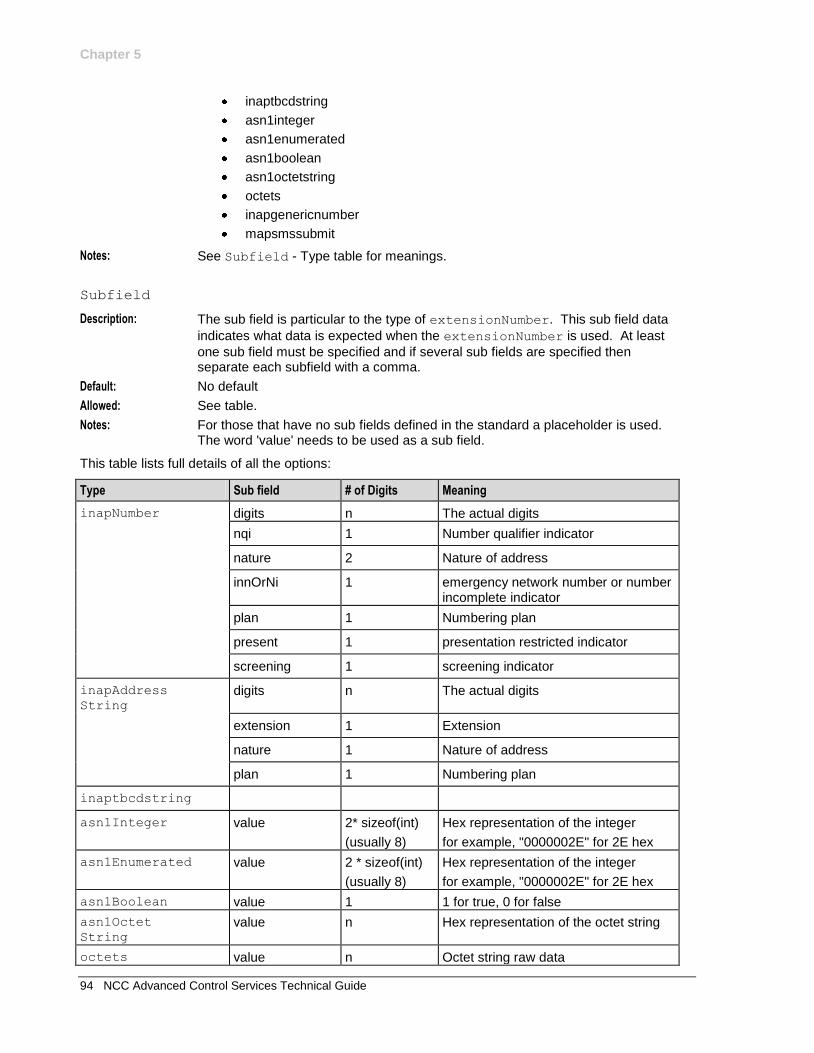
Chapter 5
94 NCC Advanced Control Services Technical Guide
inaptbcdstring
asn1integer
asn1enumerated
asn1boolean
asn1octetstring
octets
inapgenericnumber
mapsmssubmit
Notes: See Subfield - Type table for meanings.
Subfield
Description: The sub field is particular to the type of extensionNumber. This sub field data
indicates what data is expected when the extensionNumber is used. At least
one sub field must be specified and if several sub fields are specified then separate each subfield with a comma.
Default: No default
Allowed: See table.
Notes: For those that have no sub fields defined in the standard a placeholder is used. The word 'value' needs to be used as a sub field.
This table lists full details of all the options:
Type Sub field # of Digits Meaning
inapNumber digits n The actual digits
nqi 1 Number qualifier indicator
nature 2 Nature of address
innOrNi 1 emergency network number or number incomplete indicator
plan 1 Numbering plan
present 1 presentation restricted indicator
screening 1 screening indicator
inapAddress String
digits n The actual digits
extension 1 Extension
nature 1 Nature of address
plan 1 Numbering plan
inaptbcdstring
asn1Integer value 2* sizeof(int)
(usually 8)
Hex representation of the integer
for example, "0000002E" for 2E hex
asn1Enumerated value 2 * sizeof(int)
(usually 8)
Hex representation of the integer
for example, "0000002E" for 2E hex
asn1Boolean value 1 1 for true, 0 for false
asn1Octet String
value n Hex representation of the octet string
octets value n Octet string raw data
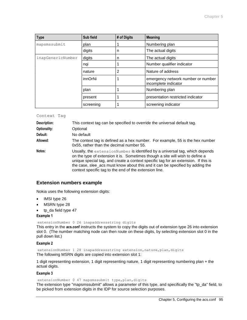
Chapter 5
Chapter 5, Configuring the acs.conf 95
Type Sub field # of Digits Meaning
mapsmssubmit plan 1 Numbering plan
digits n The actual digits
inapGenericNumber digits n The actual digits
nqi 1 Number qualifier indicator
nature 2 Nature of address
innOrNi 1 emergency network number or number incomplete indicator
plan 1 Numbering plan
present 1 presentation restricted indicator
screening 1 screening indicator
Context Tag
Description: This context tag can be specified to override the universal default tag.
Optionality: Optional
Default: No default
Allowed: The context tag is defined as a hex number. For example, 55 is the hex number 0x55, rather than the decimal number 55.
Notes: Usually, the extensionNumber is identified by a universal tag, which depends
on the type of extension it is. Sometimes though a site will wish to define a unique special tag, and create a context specific tag for an extension. If this is the case, slee_acs must know about this and it can be specified by adding the context specific tag to the end of the extension line.
Extension numbers example
Nokia uses the following extension digits:
IMSI type 26
MSRN type 28
tp_da field type 47
Example 1
extensionNumber 0 26 inapaddressstring digits
This entry in the acs.conf instructs the system to copy the digits out of extension type 26 into extension slot 0. (The number matching node can then route on these digits, by selecting extension slot 0 in the pull down list.)
Example 2
extensionNumber 1 28 inapaddressstring extension,nature,plan,digits
The following MSRN digits are copied into extension slot 1:
1 digit representing extension, 1 digit representing nature, 1 digit representing numbering plan + the actual digits.
Example 3
extensionNumber 0 47 mapsmssubmit type,plan,digits
The extension type "mapsmssubmit" allows a parameter of this type, and specifically the "tp_da" field, to be picked from extension digits in the IDP for source selection purposes.
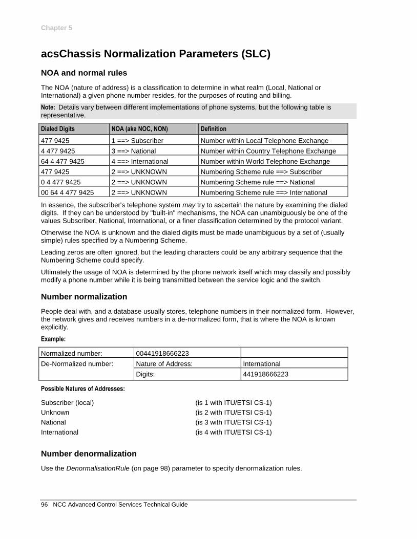
Chapter 5
96 NCC Advanced Control Services Technical Guide
acsChassis Normalization Parameters (SLC)
NOA and normal rules
The NOA (nature of address) is a classification to determine in what realm (Local, National or International) a given phone number resides, for the purposes of routing and billing.
Note: Details vary between different implementations of phone systems, but the following table is representative.
Dialed Digits NOA (aka NOC, NON) Definition
477 9425 1 ==> Subscriber Number within Local Telephone Exchange
4 477 9425 3 ==> National Number within Country Telephone Exchange
64 4 477 9425 4 ==> International Number within World Telephone Exchange
477 9425 2 ==> UNKNOWN Numbering Scheme rule ==> Subscriber
0 4 477 9425 2 ==> UNKNOWN Numbering Scheme rule ==> National
00 64 4 477 9425 2 ==> UNKNOWN Numbering Scheme rule ==> International
In essence, the subscriber's telephone system may try to ascertain the nature by examining the dialed digits. If they can be understood by "built-in" mechanisms, the NOA can unambiguously be one of the values Subscriber, National, International, or a finer classification determined by the protocol variant.
Otherwise the NOA is unknown and the dialed digits must be made unambiguous by a set of (usually simple) rules specified by a Numbering Scheme.
Leading zeros are often ignored, but the leading characters could be any arbitrary sequence that the Numbering Scheme could specify.
Ultimately the usage of NOA is determined by the phone network itself which may classify and possibly modify a phone number while it is being transmitted between the service logic and the switch.
Number normalization
People deal with, and a database usually stores, telephone numbers in their normalized form. However, the network gives and receives numbers in a de-normalized form, that is where the NOA is known explicitly.
Example:
Normalized number: 00441918666223
De-Normalized number: Nature of Address: International
Digits: 441918666223
Possible Natures of Addresses:
Subscriber (local) (is 1 with ITU/ETSI CS-1)
Unknown (is 2 with ITU/ETSI CS-1)
National (is 3 with ITU/ETSI CS-1)
International (is 4 with ITU/ETSI CS-1)
Number denormalization
Use the DenormalisationRule (on page 98) parameter to specify denormalization rules.
Chapter 5
Chapter 5, Configuring the acs.conf 97
Global and service specific normalization
Each individual service decides what numbers need to be normalized, however, the ACS framework provides the conversion functionality. Conversion rules can be global, or specific for each individual
service (defined by the ServiceEntry parameters).
Global rules are defined within the acsChassis section, while specific service rules are defined in
separate service sections in the acs.conf. Global normalization rules will be used by services for which no specific sections are defined in the acs.conf.
Normalization parameters
The conversion mapping is created through the acs.conf file using the following parameters:
NormalUnknownNOA
Syntax:
Description: This value is the NOA to be used in the code to denormalize a number.
Default: No default
Type:
Optionality:
Allowed:
Notes: The rules to normalize and denormalize numbers should be set up separately. There is no single configuration option to do both.
Example:
NormalUseHex
Syntax:
Description: Indicates whether the converted number is a hexadecimal or decimal value.
Type:
Optionality:
Allowed: 0 false (decimal value)
1 true (hexadecimal value)
Default: 0
Notes:
Example:
NormalisationRule
Syntax: NormalisationRule
(inNOA,inPrefix,noOfDigitsToRemove,outPrefix[,minLength[,maxL
ength]]
Description: Defines a conversion rule for incoming (denormalized) numbers to normalized numbers.
Default: No default
Type: Array of parameters
Optionality: Optional
Allowed: Valid list of parameters
Notes: Normalization rules are applied based on the best match for the number and NoA,
and the value of inPrefix. The rule with the longest matching inPrefix value is
applied. If there is more than one matching rule with the same inPrefix value,
Chapter 5
98 NCC Advanced Control Services Technical Guide
then the last rule in the list of matching rules is applied.
Example: NormalisationRule (4,0,0,000)
DenormalisationRule
Syntax: DenormalisationRule
(inPrefix,outNOA,noOfDigitsToRemove,outPrefix[,minLength[,max
Length]])
DenormalisationRule
(noa,inNOA,inPrefix,outNOA,noOfDigitsToRemove,DigitsToAdd)
Description: Defines conversion rule for normalized (internal) numbers to (outgoing) denormalized numbers.
Default: No denormalization
Type: Array of parameters
Optionality: Optional
Allowed: Valid list of parameters following either the first or second format.
Notes: There are NO spaces within either rule format.
Example: DenormalisationRule (800,3,0,-,7,9)
DenormalisationRule (noa,3,E,4,0,999)
inNOA
Syntax: inNOA
Description: Incoming numbers which match this NOA and inPrefix will have the rule
applied.
Type: Decimal integer
Optionality: Mandatory
Allowed:
Default:
Notes:
Example: 3
inPrefix
Syntax: inPrefix
Description: All numbers with this prefix have this rule applied.
Type: String
Optionality: Mandatory
Allowed: 0-9A-F#*-
Default: No default
Notes: Incoming prefix can be 'E' to specify the global rule for a given NOA, which will map anything not matched by a prefix.
For NormalisationRule, the number may also need to match the inNOA.
Example: 00
NOAToAdd
Syntax: NOAToAdd
Description: The NOA is set to NOAToAdd after denormalization.
Default: No default
Type: Hexadecimal integer

Chapter 5
Chapter 5, Configuring the acs.conf 99
Optionality: Mandatory
Allowed:
Notes: Only applies to DenormalisationRule.
Example: 1
noOfDigitsToRemove
Syntax: noOfDigitsToRemove
Description: This number of digits are stripped from the beginning of the number.
Type: Decimal integer
Optionality: Mandatory
Allowed:
Default: No default
Notes: Outgoing prefix can be 'E' to specify no digits to add to the digit string.
Example: 2
outNOA
Syntax: outNOA
Description: Outgoing numbers which match this NOA and outPrefix will have the rule
applied.
Type: Decimal integer
Optionality: Mandatory
Allowed:
Default:
Notes: Only applies in DenormalisationRule.
Example: 3
outPrefix
Syntax: outPrefix
Description: These digits are prepended to the number, after stripping any as specified by
NoOfDigitsToRemove.
Type: String
Optionality: Mandatory
Allowed: 0-9A-F#*-
Default: No default
Notes: Outgoing prefix can be 'E' to specify no digits to add to the digit string.
Example: 04
minLength
Syntax: minLength
Description: The minimum length number must be to trigger the rule.
Default: 0
Type: Integer
Optionality: Optional (Required if maxLength is used.)
Allowed:
Notes: If a minimum parameter is present and a maximum parameter is not provided then

Chapter 5
100 NCC Advanced Control Services Technical Guide
only the minimum check is carried out.
Example: 6
maxLength
Syntax: maxLength
Description: The maximum length number can be to trigger the rule.
Default: 999
Type: Integer
Optionality: Optional (if used, minLength is required.)
Allowed:
Notes: If a minimum parameter is present and a maximum parameter is not provided then only the minimum check is carried out.
Example: 9
normaliseTerminationNumber
Syntax:
Description: Set the engine's terminationNumber, which is printed as TN in the EDR.
Default:
Type:
Optionality:
Allowed: 0 The digits sent over the network in the connect.
1 The normalized number sent to the service loader.
Default: 0
Notes: This parameter is only specified at the global level.
Example:
normaliseServiceNumber
Syntax:
Description: Set the EDR serviceNumber, which is printed as SN in the EDR.
Type:
Optionality:
Allowed: 0 The digits received over the network in the IDP.
1 The normalized number received from the service loader.
Default: 0
Notes: This parameter is only specified at the global level.
Example:
Play Number Announcement node denormalization rules
If denormalization is turned on, the number will be denormalized according to the rules in one of the following:
The section of acs.conf specified by the NumberRulesSection entry in the
acsPlayNumberAnnouncement section
If the NumberRulesSection entry does not specify an acs.conf section, the
NumberRulesInteraction section.
Chapter 5
Chapter 5, Configuring the acs.conf 101
Example: This text shows an example number denormalization configuration from acs.conf using acsPlayNumberAnnouncement.
acsPlayNumberAnnouncement
NumberRulesSection NumberRulesPNAN
:
NumberRulesPNAN
DenormalisationRule (62,2,2,E)
DenormalisationRule (E,2,0,00)
:
If no denormalization rule matches, the number will be played in its normalized form.
Example 1
This example shows a NormalisationRule.
NormalisationRule (4,E,0,00)
Results: Will normalize:
International Nature Of Address (4) with any prefix (E).
Will not strip any digits (0), but will prefix 00 to the number.
This rule would normalize [International, "6449391234"] to "006449391234".
Example 2
This example shows a DenormalisationRule (on page 98).
DenormalisationRule (0,3,1,E)
Results: Will denormalize numbers beginning with 0.
Set the Nature of Address to National (3).
Strip one digit (1) but will not prefix anything (E).
This rule would denormalize "049391234" to [National, "49391234"].
Example 3
This example shows a DenormalisationRule (on page 98), using the second format.
DenormalisationRule (noa,3,E,4,0,999)
Results: This rule will:
denormalize any ICA outgoing number with an NoA of 3
convert the NoA to 4
add "999" to it.
acsChassis SLEE Event Size Parameter (SLC)
Introduction
The minimumSizeOfConnectSLeeEvent parameter defines the minimum size for SLEE events
containing connect operations from ACS.
You define the minimumSizeOfConnectSLeeEvent parameter globally in the acsChassis section
of acs.conf. You can also override the global value on a per service basis by defining an override value for the parameter in the service configuration.
For more information, see Configuring minimumSizeOfConnectSleeEvent per service (on page 109).
Chapter 5
102 NCC Advanced Control Services Technical Guide
Important: For this configuration to work, you must also define MAXEVENTS in SLEE.cfg of at least the
sizes specified for minimumSizeOfConnectSleeEvent.
minimumSizeOfConnectSleeEvent
Syntax: minimumSizeOfConnectSleeEvent event_size
Description: Sets the minimum size in bytes for SLEE events containing connect operations. You can override the global definition for the minimum size for a service by including a definition for this parameter in the service configuration.
Type: Integer
Optionality: Optional (default used if not set).
Allowed: A valid integer
Default: 1024
Notes: You must also configure MAXEVENTS in the SLEE.cfg file for each
minimumSizeOfConnectSleeEvent definition, using the same value, or a
higher value.
Example: minimumSizeOfConnectSleeEvent 16384
acsChassis ServiceEntry Configuration (SLC)
Introduction
A service entry is a line in acs.conf telling slee_acs how to handle new calls arriving from the SLEE. They specify:
Which service loader should handle calls from which SLEE service handle
How the InitialDP parameters are translated into the call context and outgoing Connect variables
Service loaders:
Load control plans, profiles, etc.
Copy InitialDP parameters to ACS call context variables
Construct outgoing Connects.
Note: The SLEE service handle is derived from the SLEE.cfg file. They are based on the:
INAP service key in the InitialDP
Originating SCCP sub-system number of the message containing the InitialDP
For more information about SLEE.cfg service handles, see SLEE Technical Guide.
Syntax
In acs.conf, ServiceEntry lines may take one of the following forms.
First form
ServiceEntry(ServiceName,libname)
Second form
ServiceEntry(ServiceName,CallType,libname)
Third form
ServiceEntry(ServiceName,NetworkCPSource,LogicalCPSource,libname)
Fourth form
ServiceEntry(ServiceName,NetworkCPSource,LogicalCPSource,ConnectCLISource,libname)
Fifth form
Chapter 5
Chapter 5, Configuring the acs.conf 103
ServiceEntry(ServiceName,NetworkCPSource,LogicalCPSource,PendingTNSource,ConnectCLIS
ource,libname)
Sixth form
ServiceEntry(ServiceName,NetworkCPSource,LogicalCPSource,PendingTNSource,ConnectCLIS
ource,RedirectingPartyID,libname)
Seventh form
ServiceEntry(ServiceName,NetworkCPSource,LogicalCPSource,PendingTNSource,ConnectCLIS
ource,RedirectingPartyID,OriginalCalledPartyID,libname)
Parameters
Here are the definitions for each parameter.
ServiceName
Syntax: See Allowed.
Description: This is the name of the service this entry defines. This parameter is used to identify the Control Plan to use.
Type: String
Optionality: Mandatory
Allowed: ACS slee_acs uses the service number (usually derived from the called party number) in the ACS_SN_CALL_PLAN_ACTIVATION table.
a string containing ACS_Outgoing
slee_acs uses the logical calling party number in the ACS_CLI_CALL_PLAN_ACTIVATION table.
Note: Must match the service handle name in the SLEE configuration file (SLEE.cfg) for this application.
Default: None
Notes:
Example: MO_ACS_Outgoing
CallType
Syntax: Type
Description: The type of the call. This parameter is used to identify the Control Plan to use.
Type: String
Optionality: If using the second ServiceEntry form, this parameter is mandatory.
This parameter cannot be set in any other form.
Chapter 5
104 NCC Advanced Control Services Technical Guide
Allowed: ACS If the service handle is "ACS", slee_acs uses the service number (usually derived from the called party number) in the ACS_SN_CALL_PLAN_ACTIVATION table.
ACS_Outgoing If the service handle contains "ACS_Outgoing", slee_acs uses the logical calling party number in the ACS_CLI_CALL_PLAN_ACTIVATION table.
FixedControlPlanName A string which corresponds to a control plan name.
Default: None
Notes: Usage 2 form is deprecated. If used, the callType parameter is ignored, and an alarm is produced: acsParseServiceLine: acs.conf contains old ServiceEntry fmt -
field2 ignored.
Example: MO_ACS_Outgoing
NetworkCPSource
Syntax:
Description: Sets the CC Calling Network Address call context variable.
Type: String
Optionality: If using the third, fourth, fifth, sixth and seventh ServiceEntry forms, this
parameter is mandatory.
This parameter cannot be set in any other form.
Allowed: See Settings table (see "Extraction sources in IDP" on page 106).
Default: CANLcanl
Notes: CC Calling Network Address can be selected in CPE feature node configuration screens.
It describes the location of the calling party relative to the network. This parameter defines where the subscriber is. This is used in the Geographical Routing feature node. It can also be used in other services (for example, for CLIxDN tables in CCS, to calculate how much the call will cost).
NetworkCPSource and LogicalCPSource can be the same. They will be
different when the calling party has call-forwarded or is roaming internationally.
Example: LCANlcan
LogicalCPSource
Syntax:
Description: Sets the CC Calling Logical Number call context variable.
Type: String
Optionality: If using the third, fourth, fifth, sixth and seventh ServiceEntry forms, this
parameter is mandatory.
This parameter cannot be set in any other form.
Allowed: See Settings table (see "Extraction sources in IDP" on page 106).
Default: lLcCaAnN
Notes: CC Calling Logical Number can be selected in CPE feature node configuration
Chapter 5
Chapter 5, Configuring the acs.conf 105
screens.
It describes the identity of the calling party. This parameter defines who the subscriber is and, for billing purposes, who will pay.
This is used in the Call Filtering feature node.
NetworkCPSource and LogicalCPSource can be the same. They will be
different when the calling party has call-forwarded or is roaming internationally.
Example: cClLaAnN
PendingTNSource
Syntax:
Description: Sets the CC Pending Termination Number call context variable.
Type: String
Optionality: If using the fifth, sixth and seventh ServiceEntry forms, this parameter is
mandatory.
This parameter cannot be set in any other form.
Allowed: See Settings table (see "Extraction sources in IDP" on page 106).
Default: dD
Notes: CC Pending Termination Number can be selected in CPE feature node configuration screens. If it is not changed during a control plan, it is used to populate the destinationRoutingAddress (DRA) parameter in Connect operations sent to the SSP.
Example: fFdD
ConnectCLISource
Syntax:
Description: Sets the callingPartyNumber in Connect operations which are sent to the SSP.
Type: String
Optionality: If using the fourth, fifth, sixth and seventh ServiceEntry forms, this parameter is
mandatory.
This parameter cannot be set in any other form.
Allowed: See Extraction sources in IDP (on page 106).
Default: E
Notes:
Example: cC
RedirectingPartyID
Syntax:
Description: Populates the redirectingPartyID parameter in Connect operations which are sent to the SSP.
Type: String
Optionality: If using the sixth and seventh ServiceEntry forms, this parameter is mandatory.
This parameter cannot be set in any other form.
Allowed: See Extraction sources in IDP (on page 106).
Default: E
Notes:
Example: cC
Chapter 5
106 NCC Advanced Control Services Technical Guide
OriginalCalledPartyID
Syntax:
Description: Populates the originalCalledPartyID parameter in Connect operations which are sent to the SSP.
Type: String
Optionality: If using the seventh ServiceEntry form, this parameter is mandatory.
This parameter cannot be set in any other form.
Allowed: See Extraction sources in IDP (on page 106).
Default: fFE
Notes:
Example: fFdD
libname
Syntax:
Description: The name of the slee_acs service loader plug-in library to use for this service.
Type: String
Optionality: Mandatory
Allowed:
Default: None
Notes: slee_acs will look for the library in all locations specified in the LD_LIBRARY environmental variable. This is usually set up in the .profile of acs_oper.
The service loader library required to run a service application will be installed by the application's packages.
Example: libacsService.so
Extraction sources in IDP
Extraction source settings define where slee_acs extracts data to populate the call context and outgoing Connects from. Each letter corresponds to a parameter in the InitialDP. slee_acs takes the first valid value, checking each InitialDP parameter in the order the letters appear. This can be used to:
Set up roaming calls so the called and calling parties are swapped so they can be billed correctly
Ensure a call context or outgoing Connect variable is present by using more than one source value (for example, using redirectingPartyID and callingPartyNumber to populate the CC Calling Party Number call context variable)
Ensure a call context or outgoing Connect is empty
Note: The settings can only be used for these ServiceEntry parameters:
NetworkCPSource
LogicalCPSource
PendingTNSource
ConnectCLISource
RedirectingPartyID
OriginalCalledPartyID
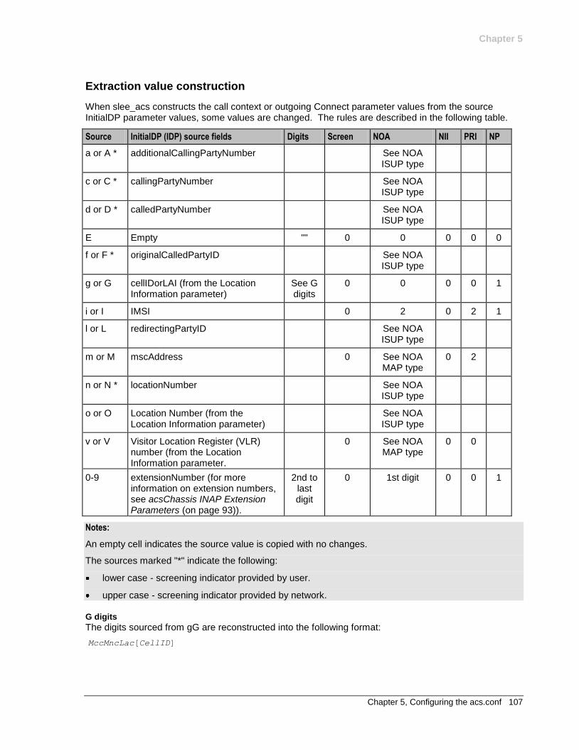
Chapter 5
Chapter 5, Configuring the acs.conf 107
Extraction value construction
When slee_acs constructs the call context or outgoing Connect parameter values from the source InitialDP parameter values, some values are changed. The rules are described in the following table.
Source InitialDP (IDP) source fields Digits Screen NOA NII PRI NP
a or A * additionalCallingPartyNumber See NOA ISUP type
c or C * callingPartyNumber See NOA ISUP type
d or D * calledPartyNumber See NOA ISUP type
E Empty "" 0 0 0 0 0
f or F * originalCalledPartyID See NOA ISUP type
g or G cellIDorLAI (from the Location Information parameter)
See G digits
0 0 0 0 1
i or I IMSI 0 2 0 2 1
l or L redirectingPartyID See NOA ISUP type
m or M mscAddress 0 See NOA MAP type
0 2
n or N * locationNumber See NOA ISUP type
o or O Location Number (from the Location Information parameter)
See NOA ISUP type
v or V Visitor Location Register (VLR) number (from the Location Information parameter.
0 See NOA MAP type
0 0
0-9 extensionNumber (for more information on extension numbers, see acsChassis INAP Extension Parameters (on page 93)).
2nd to last digit
0 1st digit 0 0 1
Notes:
An empty cell indicates the source value is copied with no changes.
The sources marked "*" indicate the following:
lower case - screening indicator provided by user.
upper case - screening indicator provided by network.
G digits
The digits sourced from gG are reconstructed into the following format:
MccMncLac[CellID]
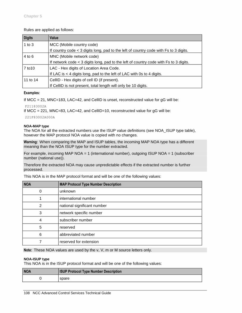
Chapter 5
108 NCC Advanced Control Services Technical Guide
Rules are applied as follows:
Digits Value
1 to 3 MCC (Mobile country code)
If country code < 3 digits long, pad to the left of country code with Fs to 3 digits.
4 to 6 MNC (Mobile network code)
If network code < 3 digits long, pad to the left of country code with Fs to 3 digits.
7 to10 LAC - Hex digits of Location Area Code.
If LAC is < 4 digits long, pad to the left of LAC with 0s to 4 digits.
11 to 14 CellID - Hex digits of cell ID (if present).
If CellID is not present, total length will only be 10 digits.
Examples:
If MCC = 21, MNC=183, LAC=42, and CellID is unset, reconstructed value for gG will be:
F21183002A
If MCC = 221, MNC=83, LAC=42, and CellID=10, reconstructed value for gG will be:
221F83002A000A
NOA-MAP type
The NOA for all the extracted numbers use the ISUP value definitions (see NOA_ISUP type table), however the MAP protocol NOA value is copied with no changes.
Warning: When comparing the MAP and ISUP tables, the incoming MAP NOA type has a different meaning than the NOA ISUP type for the number extracted.
For example, incoming MAP NOA = 1 (international number), outgoing ISUP NOA = 1 (subscriber number (national use)).
Therefore the extracted NOA may cause unpredictable effects if the extracted number is further processed.
This NOA is in the MAP protocol format and will be one of the following values:
NOA MAP Protocol Type Number Description
0 unknown
1 international number
2 national significant number
3 network specific number
4 subscriber number
5 reserved
6 abbreviated number
7 reserved for extension
Note: These NOA values are used by the v, V, m or M source letters only.
NOA-ISUP type
This NOA is in the ISUP protocol format and will be one of the following values:
NOA ISUP Protocol Type Number Description
0 spare
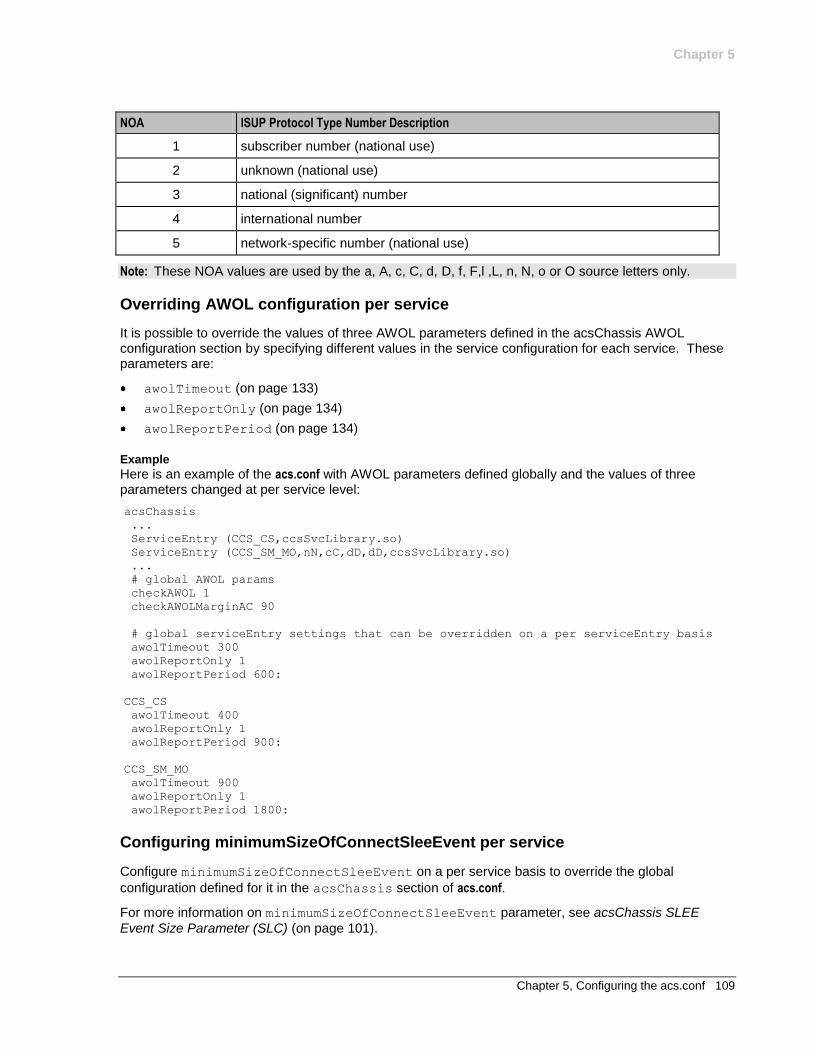
Chapter 5
Chapter 5, Configuring the acs.conf 109
NOA ISUP Protocol Type Number Description
1 subscriber number (national use)
2 unknown (national use)
3 national (significant) number
4 international number
5 network-specific number (national use)
Note: These NOA values are used by the a, A, c, C, d, D, f, F,l ,L, n, N, o or O source letters only.
Overriding AWOL configuration per service
It is possible to override the values of three AWOL parameters defined in the acsChassis AWOL configuration section by specifying different values in the service configuration for each service. These parameters are:
awolTimeout (on page 133)
awolReportOnly (on page 134)
awolReportPeriod (on page 134)
Example
Here is an example of the acs.conf with AWOL parameters defined globally and the values of three parameters changed at per service level:
acsChassis
...
ServiceEntry (CCS_CS,ccsSvcLibrary.so)
ServiceEntry (CCS_SM_MO,nN,cC,dD,dD,ccsSvcLibrary.so)
...
# global AWOL params
checkAWOL 1
checkAWOLMarginAC 90
# global serviceEntry settings that can be overridden on a per serviceEntry basis
awolTimeout 300
awolReportOnly 1
awolReportPeriod 600:
CCS_CS
awolTimeout 400
awolReportOnly 1
awolReportPeriod 900:
CCS_SM_MO
awolTimeout 900
awolReportOnly 1
awolReportPeriod 1800:
Configuring minimumSizeOfConnectSleeEvent per service
Configure minimumSizeOfConnectSleeEvent on a per service basis to override the global
configuration defined for it in the acsChassis section of acs.conf.
For more information on minimumSizeOfConnectSleeEvent parameter, see acsChassis SLEE
Event Size Parameter (SLC) (on page 101).
Chapter 5
110 NCC Advanced Control Services Technical Guide
Example
This example configuration defines a global value for the minimumSizeOfConnectSleeEvent
parameter in the acsChassis section of acs.conf, and a service specific entry to override the global
value for the CCS_BPL service.
In the example, all SLEE events that contain connect operations will be at least 16384 bytes in size.
However, if the service is CCS_BPL, then these events will be at least 163840 bytes in size because the
service specific entry will override the acsChassis entry.
acsChassis
...
ServiceEntry (CCS_BPL,ccsSvcLibrary.so)
...
# global minimumSizeOfConnectSleeEvent setting that can be overridden on a per
serviceEntry basis
minimumSizeOfConnectSleeEvent 16384
CCS_BPL
# Defines parameters that are specific to the CCS_BPL service
...
minimumSizeOfConnectSleeEvent 163840
acsChassis SRF Configuration (SLC)
Introduction
The srf parameter defines an SRF (Specialized Resource Function) name which may be referenced in
the ACS announcement configuration screens.
Parameter
Usage:
srf (srfName,UseETC=Y|N,Address=address_of_IP,NOA=0-
4[,TypeOfSrf=string][,tcapPreEnd=Y|N])
srfName
Syntax: srfName
Description: Unique name for this SRF entry
Type: String
Optionality: Mandatory
Allowed:
Default: No default
Notes: Resource Name on the New and Edit Announcement Entry screens must match this entry.
For more information about setting up announcements using the ACS screens, see ACS User's Guide.
Example: NAP1
UseETC
Syntax:
Description: Whether or not to Establish a Temporary Connection directly to an external Intelligent Peripheral.
Type: Boolean
Optionality: Mandatory

Chapter 5
Chapter 5, Configuring the acs.conf 111
Allowed: Y An external IP is contacted directly from the SLC. This establishes a temporary connection to that IP.
N
Default: N
Notes:
Example: UseETC=Y
Address
Syntax: Address=host|ip_addr
Description: This is the hostname or address of an external Intelligent Peripheral.
Type: Hostname or IP address
Optionality: Mandatory
You do not need to set a value if the IP is internal to the switch.
Allowed:
Default: No default
Notes: Required if UseETC is set to Y.
If the IP is internal, do not specify any value.
Example: Address=C400102
NOA
Syntax: NOA=value
Description: The Nature of Address indicator.
Type: Integer
Optionality:
Allowed: 0 spare
1 subscriber number
2 unknown
3 national significant number
4 international significant number
Default: 0
Notes:
Example: NOA=3
TypeOfSrf
Syntax: TypeOfSrf=string
Description: What type of Intelligent Peripheral this SRF entry refers to.
Type: String
Optionality:
Allowed: NAP
NOKIA
Nortel Only required on older Nortel internal SRF implementations.
Other No SRF-type-specific extensions will be activated.
ZTE
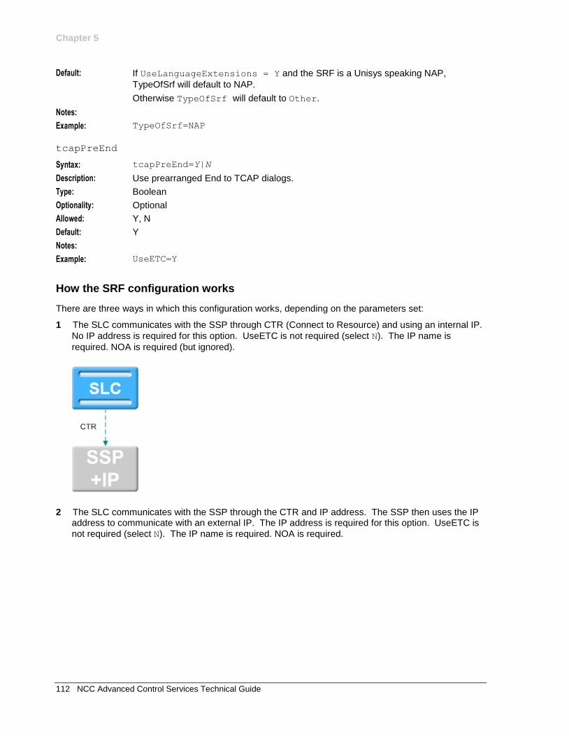
Chapter 5
112 NCC Advanced Control Services Technical Guide
Default: If UseLanguageExtensions = Y and the SRF is a Unisys speaking NAP,
TypeOfSrf will default to NAP.
Otherwise TypeOfSrf will default to Other.
Notes:
Example: TypeOfSrf=NAP
tcapPreEnd
Syntax: tcapPreEnd=Y|N
Description: Use prearranged End to TCAP dialogs.
Type: Boolean
Optionality: Optional
Allowed: Y, N
Default: Y
Notes:
Example: UseETC=Y
How the SRF configuration works
There are three ways in which this configuration works, depending on the parameters set:
1 The SLC communicates with the SSP through CTR (Connect to Resource) and using an internal IP.
No IP address is required for this option. UseETC is not required (select N). The IP name is
required. NOA is required (but ignored).
2 The SLC communicates with the SSP through the CTR and IP address. The SSP then uses the IP address to communicate with an external IP. The IP address is required for this option. UseETC is
not required (select N). The IP name is required. NOA is required.
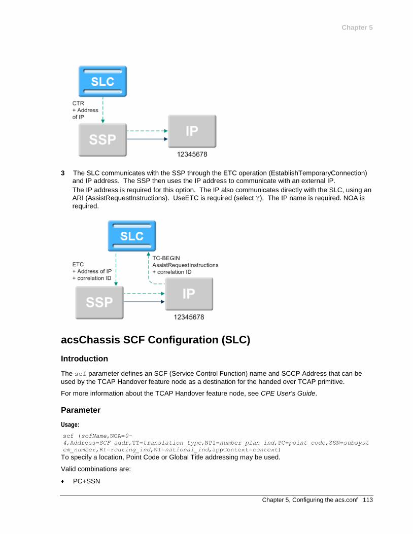
Chapter 5
Chapter 5, Configuring the acs.conf 113
3 The SLC communicates with the SSP through the ETC operation (EstablishTemporaryConnection) and IP address. The SSP then uses the IP address to communicate with an external IP.
The IP address is required for this option. The IP also communicates directly with the SLC, using an
ARI (AssistRequestInstructions). UseETC is required (select Y). The IP name is required. NOA is
required.
acsChassis SCF Configuration (SLC)
Introduction
The scf parameter defines an SCF (Service Control Function) name and SCCP Address that can be
used by the TCAP Handover feature node as a destination for the handed over TCAP primitive.
For more information about the TCAP Handover feature node, see CPE User's Guide.
Parameter
Usage:
scf (scfName,NOA=0-
4,Address=SCF_addr,TT=translation_type,NPI=number_plan_ind,PC=point_code,SSN=subsyst
em_number,RI=routing_ind,NI=national_ind,appContext=context)
To specify a location, Point Code or Global Title addressing may be used.
Valid combinations are:
PC+SSN
Chapter 5
114 NCC Advanced Control Services Technical Guide
Address+NOA
Address+TT
Address+TT+NPI
Address+NOA+TT+NPI
You can also cause an originating address to be set in the outgoing ICA request by slee_acs instead of your TCAP IF using:
scf (LocationAddress,NOA=0-4,Address=SCF_addr)
Note: Consult standard Q713 for full parameter definitions.
scfName
Syntax:
Description: The SCF Name to deliver the TCAP primitive to.
Type: String
Optionality: Required if TCAP Handover is used.
Allowed: Must match the Name from the TCAP Handover feature node configuration in the control plan.
Default: none
Notes: If you set LocationAddress in this position in the scf, slee_acs will set an originating address in the outgoing ICA request (otherwise it is set by TCAP IF).
Example: For an example of how to use this configuration in context, see Example (on page 116) SCF configuration.
Address
Syntax: SCF_addr
Description: The address of IP if an external IP is used.
Type:
Optionality:
Allowed: Address of IP or nothing if internal IP
Default: none
Notes:
Example: For an example of how to use this configuration in context, see Example (on page 116) SCF configuration.
NOA
Syntax: noa
Description: The Nature of Address indicator.
Type:
Optionality: Optional (default used if not set)
Allowed: 0 spare
1 subscriber number
2 unknown
3 national significant number
4 international significant number
Default: 0
Notes:
Example: For an example of how to use this configuration in context, see Example (on page 116).
Chapter 5
Chapter 5, Configuring the acs.conf 115
TT
Syntax: translation_type
Description: The Translation Type.
Type:
Optionality:
Allowed:
Default: none
Notes:
Example: For an example of how to use this configuration in context, see Example (on page 116) SCF configuration.
NPI
Syntax: number_plan_ind
Description: The Number Plan Indicator.
Type:
Optionality:
Allowed:
Default: none
Notes:
Example: For an example of how to use this configuration in context, see Example (on page 116) SCF configuration.
PC
Syntax: point_code
Description: The Point Code.
Type:
Optionality:
Allowed:
Default: none
Notes:
Example: For an example of how to use this configuration in context, see Example (on page 116) SCF configuration.
SSN
Syntax: subsystem_number
Description: The Sub System Number.
Type:
Optionality:
Allowed:
Default: none
Notes:
Example: For an example of how to use this configuration in context, see Example (on page 116) SCF configuration.
Chapter 5
116 NCC Advanced Control Services Technical Guide
RI
Syntax: routing_ind
Description: The Routing Indicator.
Type:
Optionality:
Allowed:
Default: none
Notes:
Example: For an example of how to use this configuration in context, see Example (on page 116) SCF configuration.
NI
Syntax: national_ind
Description: The National Indicator.
Type:
Optionality:
Allowed:
Default: none
Notes:
Example: For an example of how to use this configuration in context, see Example (on page 116) SCF configuration.
appContext
Syntax: appContext=context
Description: The application context for this scf.
Type: String
Optionality: Optional
Allowed: Any valid context:
Nokia_IDP
CAPv2_IDP
CAPv3_IDP
CAPv3_SMS
<n>.<m>.<p> - Where n, m and p are integer numbers that form an object identifier, defining the protocol to use.
Default: None
Notes: Required if the TCAP Handover node is expected to pass on the application context.
Example: appContext=CAPv2_IDP
Example
Here are examples of valid scf definitions:
scf (SCF_Name1,PC=0xADB,SSN=11)
scf (SCF_Name2,NOA=4,Address=01224)
scf (LocationAddress,NOA=4,Address=01234)
Chapter 5
Chapter 5, Configuring the acs.conf 117
About defining scfs in acs.jnlp and sms.jnlp
The values used for SCP names in the scf section of the acs.conf configuration file must match the scfs
applet parameter definition in both the acs.jnlp and the sms.jnlp files.
Example: If acs.conf contains the following two lines:
scf (SCP_Name1,PC=0xADB,SSN=11)
scf (SCP_Name2,NOA=4,Address=01224)
The applet section of the acs.jnlp and sms.jnlp files must contain a corresponding entry for the scfs
applet parameter:
<param name="scfs" value="SCP_Name1,SCP_Name2" />
For more information about configuring applet parameters in acs.jnlp and sms.jnlp, see Setting up the screens (on page 23).
acsChassis SSF Configuration (SLC)
Introduction
In acs.conf, the ssf line defines a Service Switching Function (SSF) that can be used by the Call
Initiation node as a destination for the Initiate Call Attempt.
Parameters
An ssf parameter line in acs.conf must contain at least:
1 The ssf_name parameter
2 The interface=handle parameter
3 An address specified by one of the following:
GT PC and SSN
acsChassis uses the address specification to construct address and address indicator numbers that comply with the ITU-T SS7 standard.
GT can be specified in four different ways, each defined in terms of ITU-T SS7's global titles.
1 GT1: [Address=GlobalTitleAddress, NOA=noa]
2 GT2: [Address=GlobalTitleAddress, TT=TranslationType]
3 GT3: [Address=GlobalTitleAddress, TT=TranslationType, NPI=NumberingPlanIndicator]
4 GT4: [Address=GlobalTitleAddress, TT=TranslationType, NPI=NumberingPlanIndicator, NOA=noa]
The address indicator number is made up of the PC=<pc>, SSN=<ssn>, RI=<RI> parameters.
Usage: The full syntax of an ssf line in acs.conf is:
ssf (ssf_name[, Address=GlobalTitleAddress[, NOA=noa][, TT=TranslationType[,
NPI=NumberingPlanIndicator[, NOA=noa]]]][, PC=pc, SSN=ssn][, RI=RI],
interface=handle[, appContext=objectIdentifier])
Definitions for individual parameters follow.
For more information about the address and address indicator parameters, refer to ITU-T Recommendation Q.713 Signalling Connection Control Part formats and codes.
Chapter 5
118 NCC Advanced Control Services Technical Guide
ssf_name
Syntax: ssf_name
Description: The name of the switch that appears in the configuration screen of the Call Initiation feature node.
Type: String
Optionality: Required
Allowed:
Default:
Notes: For more information about the Call Initiation feature node, see NCC Feature Nodes Reference Guide
Example: Switch_Name1
Address
Syntax: Address=GlobalTitleAddress
Description: The global title address
Type: Integer
Optionality: Optional (Mandatory if PC and SSN are not used).
Allowed:
Default:
Notes:
Example: Address=40053
NOA
Syntax: NOA = NatureOfAddress
Description: The nature of address indicator.
Type: Integer
Optionality: NOA
Allowed: Nature Of Address for number of address signals
Type of number
Even Odd
0 128 Unknown
1 129 Subscriber
2 130 Reserved for national use.
3 131 National significant.
4 132 International.
Default:
Notes:
Example: NOA=1
TT
Syntax: TT = TranslationType
Description: Directs messages to the appropriate translator. The value depends on the GT chosen under Parameters (on page 117).
Type: Integer
Optionality: Optional
Chapter 5
Chapter 5, Configuring the acs.conf 119
Allowed: GT1: not used.
GT2: 0 to 255
GT3: The ITU have not defined a translation type for this global title.
GT4: 1 to 254. For GT4, values for TranslationType are defined in the table.
Translation Type for GT4 Type
1 through 63 International
64 through 127 Spare
128 through 254 National
Default:
Notes: GT2:
Set TranslationType to 0 if the TT parameter is not to be used.
Translation types for internetwork services are assigned in ascending order, starting with 1.
Translation types for network-specific services are assigned in descending order, starting with 254.
TranslationType type may also imply the scheme used to encode address
information and a numbering plan.
Example:
NPI
Syntax: NPI = NPI
Description: Defines the numbering plan.
Type: Integer
Optionality: Optional
Allowed: 1 to 14.
Default:
Notes: This table describes the meanings of the different NPIs.
NPI Numbering Plan
1 ISDN and telephony
2 Generic
3 Data
4 Telex
5 Maritime mobile
6 Land mobile
7 ISDN and mobile
8 through 13 Spare
14 Private network
Example:
PC
Syntax: PC = pc
Description: Defines the signaling point code.
Type: Integer; hexadecimal, decimal or octal.
Optionality: Optional (Mandatory if SSN is set).
Chapter 5
120 NCC Advanced Control Services Technical Guide
Allowed: 0 to 16383 for decimal
0 to 0x3FFF for hexadecimal
0 to 037777 for octal
Default:
Notes: A decimal number must not begin with a 0.
A hexadecimal number must begin with 0x. For example, if the signaling
point code is 2780, the parameter would be PC=0xADC.
An octal number must begin with 0. For example, if the signaling point
code is 2780, the parameter would be PC=05334.
Example:
SSN
Syntax: SSN = SSN
Description: Identifies an SCCP user function.
Type: Integer
Optionality: Optional (Mandatory if PC is set).
Allowed: 0 - 255.
Default:
Notes: This table describes the values.
SSN SCCP user function
0 SSN not known or not used
1 SCCP management
2 Reserved for ITU-T allocation
3 ISDN user part
4 Operation, Maintenance and Administration part
5 Mobile application part
Globally-standardized subsystem numbers 6 through 10 have been allocated for use by GSM/UMTS.
6 Home location register
7 Visitor location register
8 Mobile switching center
9 Equipment identifier center
10 Authentication center
11 ISDN supplementary services
12 Reserved for international use
13 Broadband ISDN edge-to-edge applications
14 TC test responder
Chapter 5
Chapter 5, Configuring the acs.conf 121
National network subsystem numbers 142, 143 and 145 through 150 have been allocated for use within and between GSM/UMTS networks.
142 RANAP
143 RNSAP
145 GMLC (MAP)
146 CAP
147 gsmSCF (MAP) or IM-SSF (MAP)
148 SIWF (MAP)
149 SGSN (MAP)
150 GGSN (MAP)
National network subsystem numbers 249 through 254 have been allocated for use within GSM/UMTS networks.
249 PCAP
250 BSC (BSSAP-LE)
251 MSC (BSSAP-LE)
252 SMLC (BSSAP-LE)
253 BSS O&M (A interface)
254 BSSAP (A interface)
Example: SSN = 12
RI
Syntax: RI = RI
Description: The Routing Indicator. It identifies the address element to use for routing.
Type: Integer
Optionality: Optional
Allowed: 0 Route on SSN
1 Route on GT
Default:
Notes:
Example: RI = 1
interface
Syntax: interface = handle
Description: The handle for the SLEE interface that sends ICA messages to the SSF.
Type: String
Optionality: Mandatory
Allowed:
Default:
Notes: Must match the handle in the SLEE.cfg file. For more information, see SLEE Technical Guide.
Example: interface = sua_if
Chapter 5
122 NCC Advanced Control Services Technical Guide
appContext
Syntax: appContext=string
Description: The transaction capability (TC) object.
Type: String
Optionality: Optional
Allowed: Nokia_IDP
CAPv2_IDP
CAPv3_IDP
CAPv3_SMS
n.m.p Where n, m and p are integer numbers that form an object identifier, defining the protocol to use.
Default:
Notes: When the ICA node uses an ssf with appContext set, appContext enables you to specify the application context to pass back up to ACS in the generated IDP.
Examples: appContext=Nokia_IDP
appContext=15.36.5
Example
Here are three examples of valid ssf definitions:
ssf (SSF_Name1,PC=0xADC,SSN=11,interface=hssScIf)
ssf (SSF_Name2,NOA=1,Address=01234,interface=hssScIf)
ssf (Company,NOA=1,Address=01234,interface=VSSP, appContext=CAPv2_IDP)
About defining ssfs in acs.jnlp and sms.jnlp
The value used for ssf_name (the switch name) in the ssf section of the acs.conf configuration file must
match the ssfs applet parameter entry in the acs.jnlp and sms.jnlp files.
Example: If the acs.conf file contains the following two lines:
ssf (SwitchName1,PC=0xADC,SSN=11,interface=hssScIf)
ssf (SwitchName2,NOA=1,Address=01234,interface=hssScIf)
The applet section of the acs.jnlp and sms.jnlp files must contain a corresponding entry for the ssfs
applet parameter:
<PARAM NAME="ssfs" VALUE="SwitchName1,SwitchName2" />.
For more information about defining applet parameters in the acs.jnlp and sms.jnlp files, see Setting up the screens (on page 23).
acsChassis EDR Configuration (SLC)
Logging EDRs
The parameters listed below in this topic affect the way EDRs are logged.
Note: For EDRs to be logged at all, the acsChassis section of the acs.conf file must contain the line
CdrFile 1.
Chapter 5
Chapter 5, Configuring the acs.conf 123
TCP Network Loading
EDR files are collated on each SLC and uploaded at regular intervals to the SMS.
Files are transferred using the proprietary program cmnPushFiles. Refer to the main component diagram (on page 3).
EDR files contain a base content that has a size of approximately 350 bytes per call attempt or call disconnect. The total data size to be transferred can be computed from the call rate combined with assumptions about the complexity of the Control Plan.
A Control Plan that attempts to terminate and then terminates to a second number will generate two EDRs.
The total data will be typically distributed over a number of files.
A new EDR file is created when the old file reaches a specified age or size as defined by the
CdrFileMaxAge (on page 126) and CdrFileMaxSize (on page 126) parameters.
The CdrExtraFields and SendCIR parameters cause additional content to be written to each EDR
line. This raises the average data flow above the base 350 bytes per EDR line. The size of the additional content depends on the nature of the Control Plan. Experimentation with individual Control Plans is required to determine the size of extended EDRs.
Parameters
The following parameters are optional and may be added when required. Only one entry per parameter is allowed.
callReferenceIDAsHex
Syntax: callReferenceIDAsHex 0|1
Description: Indicates the Call Reference ID (an Octet string) in an IDP is a BCD number ASCII string or not.
Type: Boolean
Optionality: Optional (default used if not set).
Allowed: 0 (false), 1 (true)
Default: 0
Notes: If the Call Reference ID (an Octet string) in an IDP is a BCD number other than an ASCII string, for instance 0x28 0x81 0x1F 0xE3 0x29, then we need to set this option to true in order to be able to read the hex values "28811FE329" in EDR other than see unreadable characters.
Example: callReferenceIDAsHex 1
CdrClosedDirectory
Syntax: CdrClosedDirectory "path"
Description: The path to move the EDR file to when it it is flushed due to one of
CdrFileMaxAge (on page 126) or cdrFileMaxSize (on page 126) being
exceeded.
Type: String
Optionality: Optional (default used if not set).
Allowed:
Default: /IN/service_packages/SMS/cdr/closed
Warning: This parameter only changes the output of the EDR file. If this parameter is changed all other relevant parts of the platform must also be updated.
Chapter 5
124 NCC Advanced Control Services Technical Guide
Example: CdrClosedDirectory "/var/EDRs/closed"
CdrCompressCall
Syntax: CdrCompressCall 0|1
Description: Whether or not to log multiple connect attempts as one EDR.
Type: Boolean
Optionality: Optional (default used if not set).
Allowed: 0 a separate EDR will be created for each connection attempt, abort, or disconnect individually.
1 calls with multiple connect attempts are logged as one EDR. A single EDR will be generated at the end of every call, at the point where it is torn down, regardless of how the call finishes.
Default: 0
Notes: If CdrCompressCall is 0, the CdrOnAbort (on page 129) and
CdrOnDisconnect (on page 129) parameters determine if abort and/or
disconnect events generate EDRs.
Example: CdrCompressCall 0
CdrCurrentDirectory
Syntax: CdrCurrentDirectory "path"
Description: The path to write the EDR file to.
Type: String
Optionality: Optional (default used if not set).
Allowed:
Default: /IN/service_packages/SMS/cdr/current
Warning: This parameter only changes the output of the EDR file. If this parameter is changed all other relevant parts of the platform must also be updated.
Example: CdrCurrentDirectory "/var/EDRs/current"
CdrFile
Syntax: CdrFile 0|1
Description: Whether or not to log EDRs to a file.
Type: Boolean
Optionality: Optional (default used if not set).
Allowed: 0 (no), 1 (yes)
Default: 0
Notes:
Example: CdrFile 0
CdrExtraFields
Syntax: CdrExtraFields 0|1|2
Description: EngineNodes that are traversed during execution of a Control Plan will be logged and placed in the EDR (TFN tag)
Type: Integer
Optionality: Optional (default used if not set).

Chapter 5
Chapter 5, Configuring the acs.conf 125
Allowed: 0 No logging will be done
1 Track traversed feature nodes and played announcements, and record in EDR. The format is: <node fast key>-<node number>.
2 In addition to 1, track feature node substates, showing all the states the node is going through. The format is: <node fast key>-<node
number>.<state><state>...<state>
Default: 1
Notes: There is a maximum length of 1024 characters for this data.
There are no separators between the <state> fields which are all single characters as defined in Node states (on page 125) below.
Example: CdrExtraFields 1
Node states
State Number Node State State Number Node State
0 0 26 J
1 1 27 K
2 2 28 L
3 3 29 M
4 4 30 N
5 5 31 O
6 6 32 P
7 7 33 Q
8 8 34 R
9 9 35 S
10 : 36 T
11 ; 37 U
12 < 38 V
13 = 39 W
14 > 40 X
15 ? 41 Y
16 @ 42 Z
17 A 43 [
18 B 44 \
19 C 45 ]
20 D 46 ^
21 E 47 _
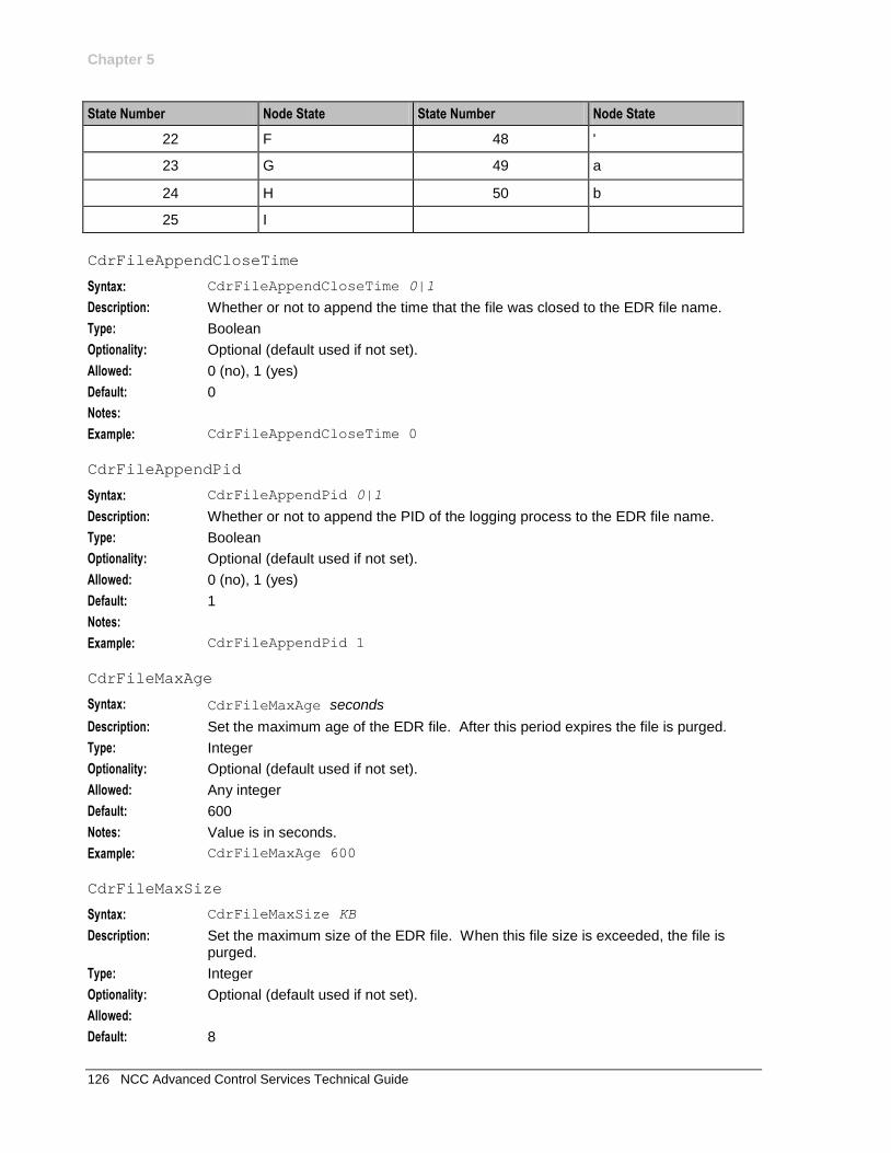
Chapter 5
126 NCC Advanced Control Services Technical Guide
State Number Node State State Number Node State
22 F 48 '
23 G 49 a
24 H 50 b
25 I
CdrFileAppendCloseTime
Syntax: CdrFileAppendCloseTime 0|1
Description: Whether or not to append the time that the file was closed to the EDR file name.
Type: Boolean
Optionality: Optional (default used if not set).
Allowed: 0 (no), 1 (yes)
Default: 0
Notes:
Example: CdrFileAppendCloseTime 0
CdrFileAppendPid
Syntax: CdrFileAppendPid 0|1
Description: Whether or not to append the PID of the logging process to the EDR file name.
Type: Boolean
Optionality: Optional (default used if not set).
Allowed: 0 (no), 1 (yes)
Default: 1
Notes:
Example: CdrFileAppendPid 1
CdrFileMaxAge
Syntax: CdrFileMaxAge seconds
Description: Set the maximum age of the EDR file. After this period expires the file is purged.
Type: Integer
Optionality: Optional (default used if not set).
Allowed: Any integer
Default: 600
Notes: Value is in seconds.
Example: CdrFileMaxAge 600
CdrFileMaxSize
Syntax: CdrFileMaxSize KB
Description: Set the maximum size of the EDR file. When this file size is exceeded, the file is purged.
Type: Integer
Optionality: Optional (default used if not set).
Allowed:
Default: 8
Chapter 5
Chapter 5, Configuring the acs.conf 127
Notes:
Example: CdrFileMaxSize 8
CdrFileUseGMT - 10291824
Syntax: CdrFileUseGMT 0|1
Description: Whether or not to add a start timestamp in GMT to the EDR filename.
Type: Boolean
Optionality: Optional (default used if not set).
Allowed: 0 - Do not add a GMT timestamp to the EDR filename.
1 - Add a GMT timestamp to the EDR filename.
Default: 0
Notes: If set to 1, the EDR filename uses this format:
application_gmtZ_start_time.cdr
If set to 0, the EDR filename uses this format:
application_start_time.cdr
Where:
application is the name of the application that triggered the EDR.
gmt is the EDR start time in GMT.
start_time is the EDR start time in local time.
Example: CdrFileUseGMT 1
CdrFileUseLocalTime - 10291824
Syntax: CdrFileUseLocalTime 0|1
Description: What timezone to use for the start and end timestamps in the EDR filename.
Type: Boolean
Optionality: Optional (default used if not set).
Allowed: 0 - Use GMT.
1 - Use local time.
Default: 0
Notes: This parameter does not affect the timestamp added if CdrFileUseGMT is set to
1(adds GMT timestamp to EDR filename).
Example: CdrFileUseLocalTime 1
CdrRemoveFields
Syntax: CdrRemoveFields 0|hex_value
Description: Mask that specifies the fields to remove from an EDR. To set the mask, sum the values used to identify each field that you want to remove, and convert to hexadecimal.
Type: Hexadecimal Integer
Optionality: Optional (default used if not set).
Allowed: Hexadecimal number that is the sum of the values for the fields you want to remove. For a list of valid values, see EDR field values table below.
Default: 0 - Do not remove any fields.
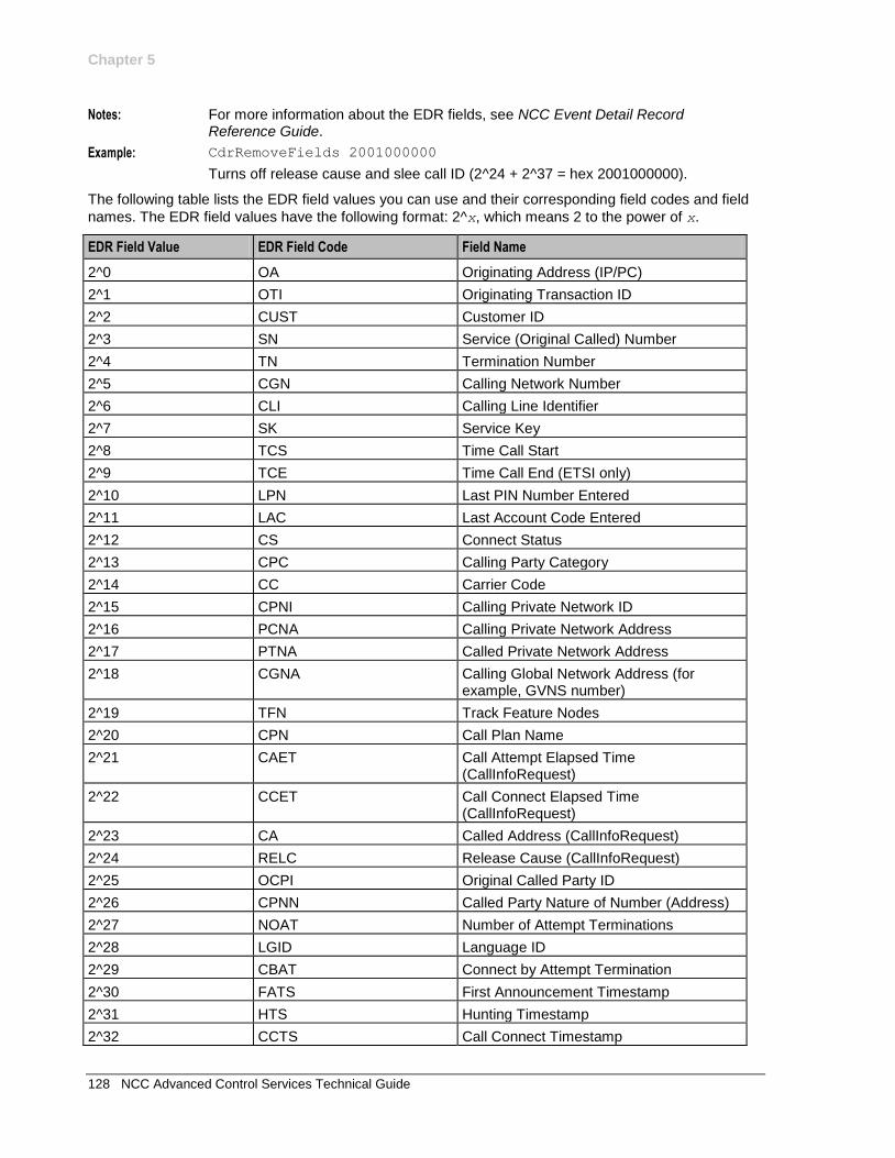
Chapter 5
128 NCC Advanced Control Services Technical Guide
Notes: For more information about the EDR fields, see NCC Event Detail Record Reference Guide.
Example: CdrRemoveFields 2001000000
Turns off release cause and slee call ID (2^24 + 2^37 = hex 2001000000).
The following table lists the EDR field values you can use and their corresponding field codes and field
names. The EDR field values have the following format: 2^x, which means 2 to the power of x.
EDR Field Value EDR Field Code Field Name
2^0 OA Originating Address (IP/PC)
2^1 OTI Originating Transaction ID
2^2 CUST Customer ID
2^3 SN Service (Original Called) Number
2^4 TN Termination Number
2^5 CGN Calling Network Number
2^6 CLI Calling Line Identifier
2^7 SK Service Key
2^8 TCS Time Call Start
2^9 TCE Time Call End (ETSI only)
2^10 LPN Last PIN Number Entered
2^11 LAC Last Account Code Entered
2^12 CS Connect Status
2^13 CPC Calling Party Category
2^14 CC Carrier Code
2^15 CPNI Calling Private Network ID
2^16 PCNA Calling Private Network Address
2^17 PTNA Called Private Network Address
2^18 CGNA Calling Global Network Address (for example, GVNS number)
2^19 TFN Track Feature Nodes
2^20 CPN Call Plan Name
2^21 CAET Call Attempt Elapsed Time (CallInfoRequest)
2^22 CCET Call Connect Elapsed Time (CallInfoRequest)
2^23 CA Called Address (CallInfoRequest)
2^24 RELC Release Cause (CallInfoRequest)
2^25 OCPI Original Called Party ID
2^26 CPNN Called Party Nature of Number (Address)
2^27 NOAT Number of Attempt Terminations
2^28 LGID Language ID
2^29 CBAT Connect by Attempt Termination
2^30 FATS First Announcement Timestamp
2^31 HTS Hunting Timestamp
2^32 CCTS Call Connect Timestamp
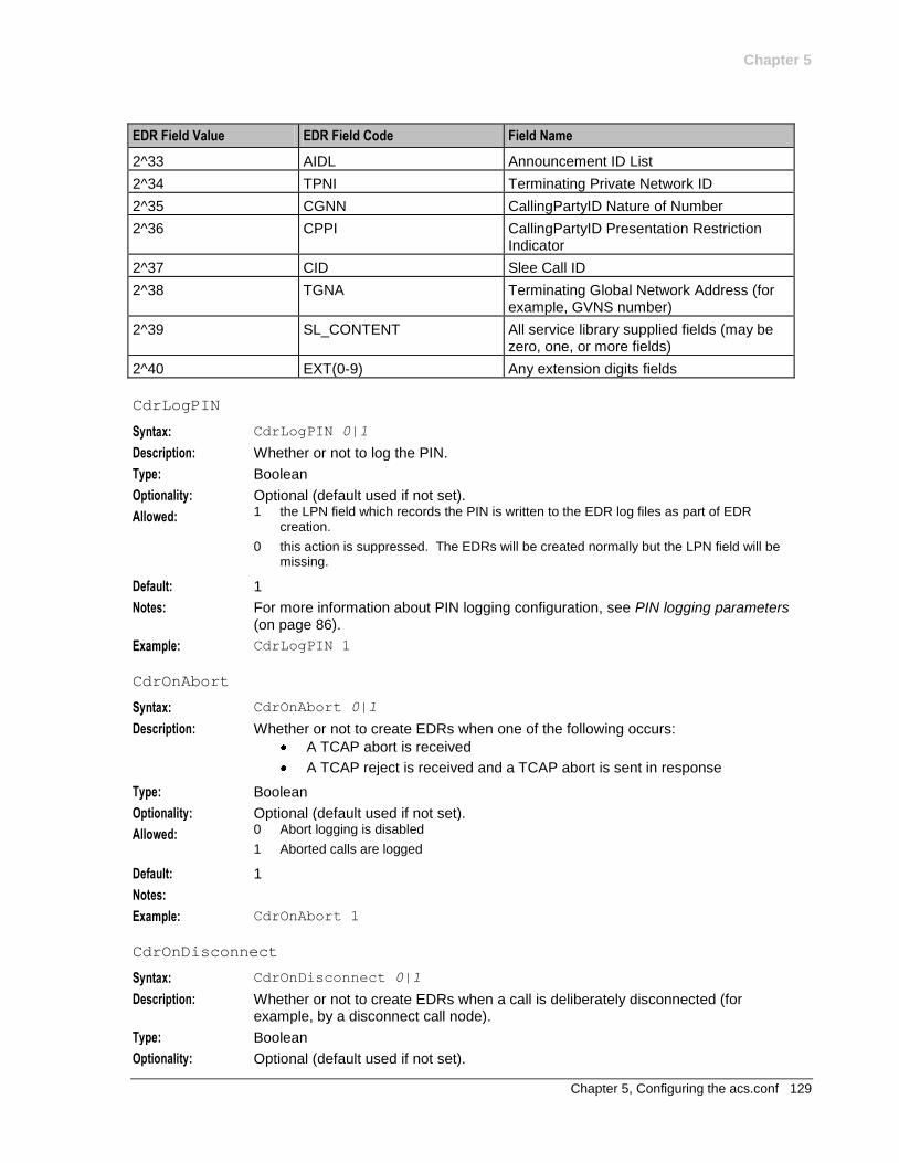
Chapter 5
Chapter 5, Configuring the acs.conf 129
EDR Field Value EDR Field Code Field Name
2^33 AIDL Announcement ID List
2^34 TPNI Terminating Private Network ID
2^35 CGNN CallingPartyID Nature of Number
2^36 CPPI CallingPartyID Presentation Restriction Indicator
2^37 CID Slee Call ID
2^38 TGNA Terminating Global Network Address (for example, GVNS number)
2^39 SL_CONTENT All service library supplied fields (may be zero, one, or more fields)
2^40 EXT(0-9) Any extension digits fields
CdrLogPIN
Syntax: CdrLogPIN 0|1
Description: Whether or not to log the PIN.
Type: Boolean
Optionality: Optional (default used if not set).
Allowed: 1 the LPN field which records the PIN is written to the EDR log files as part of EDR creation.
0 this action is suppressed. The EDRs will be created normally but the LPN field will be missing.
Default: 1
Notes: For more information about PIN logging configuration, see PIN logging parameters (on page 86).
Example: CdrLogPIN 1
CdrOnAbort
Syntax: CdrOnAbort 0|1
Description: Whether or not to create EDRs when one of the following occurs:
A TCAP abort is received
A TCAP reject is received and a TCAP abort is sent in response
Type: Boolean
Optionality: Optional (default used if not set).
Allowed: 0 Abort logging is disabled
1 Aborted calls are logged
Default: 1
Notes:
Example: CdrOnAbort 1
CdrOnDisconnect
Syntax: CdrOnDisconnect 0|1
Description: Whether or not to create EDRs when a call is deliberately disconnected (for example, by a disconnect call node).
Type: Boolean
Optionality: Optional (default used if not set).
Chapter 5
130 NCC Advanced Control Services Technical Guide
Allowed: 0 (no), 1 (yes)
Default: 1
Notes:
Example: CdrOnDisconnect 1
cdrOnForcedDisc
Syntax: cdrOnForcedDisc 0|1
Description: When set to true, forces ACS to write an EDR in the event of a forced disconnect.
Type: Boolean
Optionality: Optional (default used if not set).
Allowed: 0 (false), do not write EDR
1 (true), write EDR
Default: 0
Notes:
Example: cdrOnForceDisc 1
CdrOnHandover
Syntax: CdrOnHandover 0|1
Description: When set to true, forces ACS to write an EDR on service handover, providing the
CdrCompressCall (on page 124) parameter is set to zero (0).
Type: Boolean
Optionality: Optional (default used if not set).
Allowed: 0 (false), do not write EDR on service handover
1 (true), write EDR on service handover
Default: 0
Notes:
Example: CdrOnHandover 0
CdrResetOnWriteRELC
Syntax: CdrResetOnWriteRELC 0|1
Description: When set to true, forces ACS to reset the call release cause to zero after it has
been written to an EDR, providing the CdrCompressCall (on page 124)
parameter is set to zero (0).
Type: Boolean
Optionality: Optional (default used if not set).
Allowed: 0 (false), do not reset release cause to zero
1 (true), reset release cause to zero
Default: 0
Notes:
Example: CdrResetOnWriteRELC 1
elapsedTimesFromApplyChargingReport
Syntax: elapsedTimesFromApplyChargingReport 0|1
Description: Whether or not to calculate CAET and CCET using the ApplyChargingReport.
Type: Boolean
Optionality: Optional (default used if not set).
Chapter 5
Chapter 5, Configuring the acs.conf 131
Allowed: 0 (no), 1 (yes)
Default: 0
Notes: This is an option to use when a call has been released, in which there is no CallInformationReport.
Example: elapsedTimesFromApplyChargingReport 1
zeroElapsedTimesInCdr
Syntax: zeroElapsedTimesInCdr 0|1
Description: Whether or not to include TCS, CCET and CAET in the EDR, even in the case where call duration is zero.
Type: Boolean
Optionality: Optional (default used if not set).
Allowed: 0 (no), 1 (yes)
Default: 0
Notes:
Example: zeroElapsedTimesInCdr 1
acsChassis Service Library Configuration (SLC)
Parameter
The entries in the acsServiceLibrary topic determine configuration parameters for the
acsServiceLibrary.
ProfileOrder
Syntax: ProfileOrder (key, pro1, pro2, pro3)
Description: Defines the order of the profiles for loading and searching for traffic with a specific service key.
Type: Array
Optionality: Optional (default used if not set).
Allowed: Each pro1-3 is one of:
CUSTOMER
CALL_PLAN
SERVICE_NUMBER
Default: ProfileOrder (110,CUSTOMER,CALL_PLAN,SERVICE_NUMBER)
Notes: All three profiles must specified for each parameter.
Examples: ProfileOrder (10,CUSTOMER,CALL_PLAN,SERVICE_NUMBER) ProfileOrder (11,CALL_PLAN,SERVICE_NUMBER,CUSTOMER) ProfileOrder (12,CUSTOMER,SERVICE_NUMBER,CALL_PLAN)
Chapter 5
132 NCC Advanced Control Services Technical Guide
acsChassis Service Normalisation Parameters (SLC)
Introduction
Each service for which a ServiceEntry exists in the acs.conf can have a specific config section where
you define configuration parameters specific for that service. The name for the service section must be the same name specified in the corresponding ServiceEntry (see "acsChassis ServiceEntry Configuration (SLC)" on page 102), that is, ACS_Outgoing, CCS, VPN_Originating...
Service specific normalization parameters
The service specific normalization parameters are used to define conversion rules specific to each available service. These parameters are equivalent to those with the same name described in the acsChassis Normalization Parameters section. For a description of each, refer to Normalization parameters (on page 97).
When a service section is found in the acs.conf, the global normalization rules are ignored for that particular service and the specific rules ( if any) are used instead. In this sense, a service will only use the global configuration when no specific section is defined for it in the acs.conf. Also, in no case global and specific normalization rules will be used simultaneously within the same service.
acsChassis AWOL Configuration
AWOL processing
The ACS service supports many different call scenarios, including scenarios where the SLC is involved in the call right up to when the A or B party disconnects at the end of a conversation.
The number of entities involved in the call and managing the connection between the SSP and SLC software can lead to many complex interactions. Occasionally these interactions may not follow the INAP CS1 call model due to situations beyond the direct control of the ACS service.
In particular, ACS can be used for billable call control by using the ApplyCharging and ApplyChargingReport INAP messages. When ACS sends an ApplyCharging request to a SSP, it will expect a response within a certain time frame due to the request defining a limit on the time the call can proceed for.
Certain circumstances can occur in production networks that can cause the ApplyChargingReport to be never returned. This would in general cause the call to be left 'hanging' in the ACS service, using system and service resources that would never, usually, be freed.
To alleviate this situation, AWOL checking has been developed in the ACS service. The basic premise is that the ACS service should abort any call for which an expected ApplyChargingReport is late.
Calls that are considered as AWOL, are aborted. This will clean up all call resources within the ACS service and the SLEE.
The ACS Service will continue to process the Control Plan for the call according to the service limitations.
Defining acsChassis AWOL configuration
The acsChassis AWOL configuration section defines six AWOL parameters, two of which are global
and should only be defined in the acsChassis section of acs.conf:
checkAWOL
checkAWOLMarginAC
Chapter 5
Chapter 5, Configuring the acs.conf 133
The other parameters are defined globally in the acsChassis section; but they can also be defined in
the service configuration, per service, which will override the global values. These parameters are:
awolTimeout
awolReportOnly
awolReportPeriod
awolOverrideACRTimeout
For more information, see overriding AWOL configuration per service (on page 109).
Parameters
The following configuration parameters are provided to control AWOL checking:
checkAWOL
Syntax: checkAWOL 0|1
Description: Whether or not the ACS service should check for calls with later ApplyChargingReport messages.
Type: Boolean
Optionality: Optional (uses default if not set)
Allowed: 0 No AWOL checking is done and if the ACR is never received, the call will never be torn down
1 AWOL checking is done as defined by the other AWOL parameters.
Default: 0
Notes:
Example: checkAWOL 1
checkAWOLMarginAC
Syntax: checkAWOLMarginAC int
Description: Tolerance, in seconds, added to the apply charging timeout.
Type: Integer
Optionality: Optional
Allowed: Positive integer
Default: 30
Notes: Apply Charging operations use this parameter and not the awolTimeout parameter.
If an ApplyCharging report was sent for a call with a talk time of 60 seconds, using
the checkAWOLMarginAC parameter, it would be 90 seconds after this message
was sent before the call was considered AWOL and aborted by the ACS service.
Example: checkAWOLMarginAC 30
awolTimeout
Syntax: awolTimeout duration
Description: The time a call must be in progress before it becomes eligible for termination.
Type: Integer
Units: Seconds
Optionality: Optional
Allowed: duration 0
Chapter 5
134 NCC Advanced Control Services Technical Guide
Default: If the awolTimeout parameter is omitted, duration = 0 is assumed.
Notes: May be specified for service instance section which will override the value specified globally.
If duration is set to zero, no timer is configured and calls are never placed in a 'close' queue. .
If duration > 0, at the end of duration, a SLEE event is triggered notifying that the call should be placed in a 'close' queue.
The awolTimeout parameter can be specified in the in the acs.conf file
as a specific service entry. See acsChassis ServiceEntry Configuration (SCP) (on page 102).
This parameter is not used by any Apply Charging operations.
Example: awolTimeout 1800
awolReportOnly
Syntax: awolReportOnly 0|1
Description: Determines the type of AWOL message printed to the system log.
Type: Boolean
Optionality: Optional
Allowed: 0 For every timed out message:
report the time overdue,
the message type last sent, and
the transaction and call ID (including the service handle, where applicable).
1 For every timed out message, print only a summary report.
Default: 0
Notes: May be specified for service instance section which will override the value specified globally.
For the awolReportOnly 0 option, a examples of a message printed to
the system log is shown below. WARNING: Ending Call 268413469. TID L.0x0 R.0x0 Sent operation(s)
TCAP_INVOKE: CS1_CallInformationRequest, TCAP_INVOKE: CS1_Continue.
Received
timeout 0s ago. Service Handle CCS_ROAM. Origin Address - GT: 60181000010
SSN: 146
WARNING: Ending Call 271216901. TID L.0x0 R.0x0 Sent operation(s)
TCAP_INVOKE:
CS1_ApplyCharging, TCAP_INVOKE: CS1_ApplyCharging, TCAP_INVOKE:
CS1_ApplyCharging, TCAP_INVOKE: CS1_ApplyCharging, TCAP_INVOKE:
CS1_ApplyCharging, TCAP_INVOKE: CS1_ApplyCharging, TCAP_INVOKE:
CS1_ApplyCharging, TCAP_INVOKE: CS1_ApplyCharging, TCAP_INVOKE:
CS1_ApplyCharging, TCAP_INVOKE: CS1_ApplyCharging, TCAP_INVOKE:
CS1_ApplyCharging, TCAP_INVOKE: CS1_ApplyCharging. Received timeout 0s ago.
Service Handle CCS. Origin Address - GT: 60197030004 SSN: 146
Example: awolReportOnly 0
awolReportPeriod
Syntax: awolReportPeriod value
Description: How often, in seconds, to provide AWOL reporting.
Type: Integer
Optionality: Optional
Allowed: Positive integer
Chapter 5
Chapter 5, Configuring the acs.conf 135
Default: 900
Notes: May be specified for service instance section which will override the value specified globally.
Example: awolReportPeriod 900
awolOverrideACRTimeout
Syntax: awolOverrideACRTimeout value
Description: Specifies the period of time (seconds) within which we expect to have received an Apply Charging Report. If the ACR is not received during this time then the call is cleaned up. It is anticipated that this value will be used in data session scenarios where the return time of the ACR cannot be predicted based on the Apply Charging request.
Type: Integer
Optionality: Optional. Configurable on a per-service basis only.
Notes: If set, then the value in checkAWOLMarginAC is ignored.
Value of zero means do not override timeout from ACR.
Example: awolOverrideACRTimeout 1800
Get Hunting Number Node Configuration
Parameters
The following configuration parameter is provided to control Get Hunting Number node.
setCallData
Description: If non zero, use the VPN Set Call Data chassis action to set the RedirectingPartyID and OriginalCalledPartyID.
Type:
Optionality:
Allowed: 0, 1
Default: 0
Notes: Set to 1 if you have VPN installed.
Play Variable Part Announcement Node Configuration
Parameters
The following configuration parameters are provided to control Play Variable Part Announcement node:
NumberRulesSection
Syntax: NumberRulesSection section_name:
Description: Defines where to find custom denormalization rules when the Denormalize check box is ticked in the Play Variable Part Announcement node.
Type: String
Optionality: Optional
Allowed: Any section name defined in the acsPlayVariablePartAnnouncement section of acs.conf
Chapter 5
136 NCC Advanced Control Services Technical Guide
Default: None
Notes: The colon at the end is essential.
Example: NumberRulesSection examplePVP:
DenormalisationRule
Syntax: DenormalisationRule (parameters):
Description: Defines the denormalization rule to check for.
Type: Parameter list
Optionality: Mandatory
Allowed:
Default: None
Notes: There may be as many DenormalisationRule lines configured as needed. The colon at the end is essential.
Example: DenormalisationRule (0064,2,4,0,12):
Number Matching Node Configuration
Parameters
The following configuration parameters are provided to control Number Matching node.
RegMapFlushPeriod
Syntax: RegMapFlushPeriod secs
Description: The number of seconds between attempts to flush the compiled regular expression map.Entries are flushed if they are older than the time specified by the RegMapMaxAge parameter.
A value of 0 or less disables the flushing mechanism.
Type: Integer
Optionality: Optional.
Allowed:
Default: 600
Notes: To disable the flushing mechanism for the regular expression map, set the value to 0 (zero).
Example: RegMapFlushPeriod 600
RegMapMaxAge
Syntax: RegMapMaxAge secs
Description: The maximum number of seconds a compiled regex may remain in the map unused.
Type: Integer
Optionality: Optional (default used if not set).
Allowed:
Default: 43200 (12 hours)
Notes:
Example: RegMapMaxAge 43200
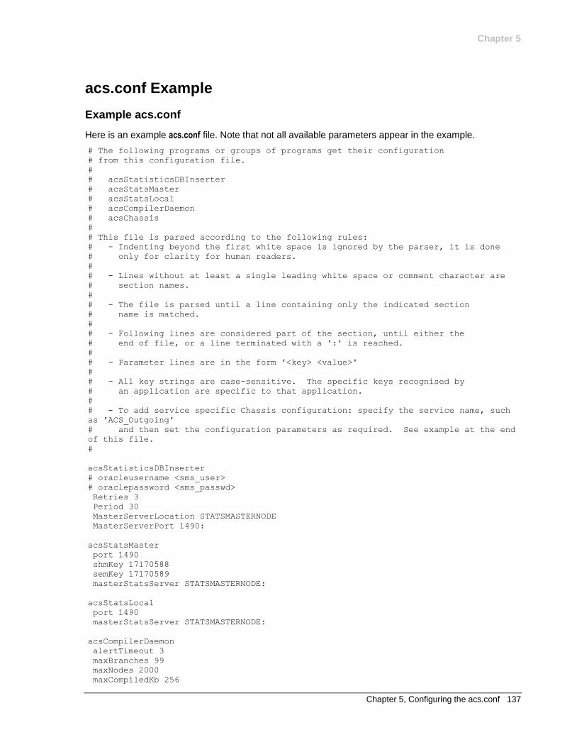
Chapter 5
Chapter 5, Configuring the acs.conf 137
acs.conf Example
Example acs.conf
Here is an example acs.conf file. Note that not all available parameters appear in the example.
# The following programs or groups of programs get their configuration
# from this configuration file.
#
# acsStatisticsDBInserter
# acsStatsMaster
# acsStatsLocal
# acsCompilerDaemon
# acsChassis
#
# This file is parsed according to the following rules:
# - Indenting beyond the first white space is ignored by the parser, it is done
# only for clarity for human readers.
#
# - Lines without at least a single leading white space or comment character are
# section names.
#
# - The file is parsed until a line containing only the indicated section
# name is matched.
#
# - Following lines are considered part of the section, until either the
# end of file, or a line terminated with a ':' is reached.
#
# - Parameter lines are in the form '<key> <value>'
#
# - All key strings are case-sensitive. The specific keys recognised by
# an application are specific to that application.
#
# - To add service specific Chassis configuration: specify the service name, such
as 'ACS_Outgoing'
# and then set the configuration parameters as required. See example at the end
of this file.
#
acsStatisticsDBInserter
# oracleusername <sms_user>
# oraclepassword <sms_passwd>
Retries 3
Period 30
MasterServerLocation STATSMASTERNODE
MasterServerPort 1490:
acsStatsMaster
port 1490
shmKey 17170588
semKey 17170589
masterStatsServer STATSMASTERNODE:
acsStatsLocal
port 1490
masterStatsServer STATSMASTERNODE:
acsCompilerDaemon
alertTimeout 3
maxBranches 99
maxNodes 2000
maxCompiledKb 256
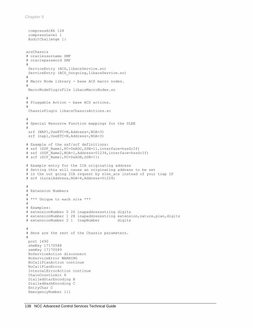
Chapter 5
138 NCC Advanced Control Services Technical Guide
compressAtKb 128
compressLevel 1
AuditChallenge 1:
acsChassis
# oracleusername SMF
# oraclepassword SMF
#
ServiceEntry (ACS,libacsService.so)
ServiceEntry (ACS_Outgoing,libacsService.so)
#
# Macro Node library - base ACS macro nodes.
#
MacroNodePluginFile libacsMacroNodes.so
#
# Pluggable Action - base ACS actions.
#
ChassisPlugin libacsChassisActions.so
#
# Special Resource Function mappings for the SLEE
#
srf (NAP1,UseETC=N,Address=,NOA=3)
srf (nap1,UseETC=N,Address=,NOA=3)
# Example of the ssf/scf definitions:
# ssf (SSF_Name1,PC=0xADC,SSN=11,interface=hssScIf)
# ssf (SSF_Name2,NOA=1,Address=01234,interface=hssScIf)
# scf (SCP_Name1,PC=0xADB,SSN=11)
# Example entry for the ICA originating address
# Setting this will cause an originating address to be set
# in the out going ICA request by slee_acs instead of your tcap IF
# scf (LocalAddress,NOA=4,Address=01224)
#
# Extension Numbers
#
# *** Unique to each site ***
#
# Examples:
# extensionNumber 0 26 inapaddressstring digits
# extensionNumber 1 28 inapaddressstring extension,nature,plan,digits
# extensionNumber 2 1 InapNumber digits
#
# Here are the rest of the Chassis parameters.
#
port 1490
shmKey 17170588
semKey 17170589
NoServiceAction disconnect
NoServiceError WARNING
NoCallPlanAction continue
NoCallPlanError
InternalErrorAction continue
ChainCountLimit 8
DialledStarEncoding B
DialledHashEncoding C
EntryChar C
EmergencyNumber 111
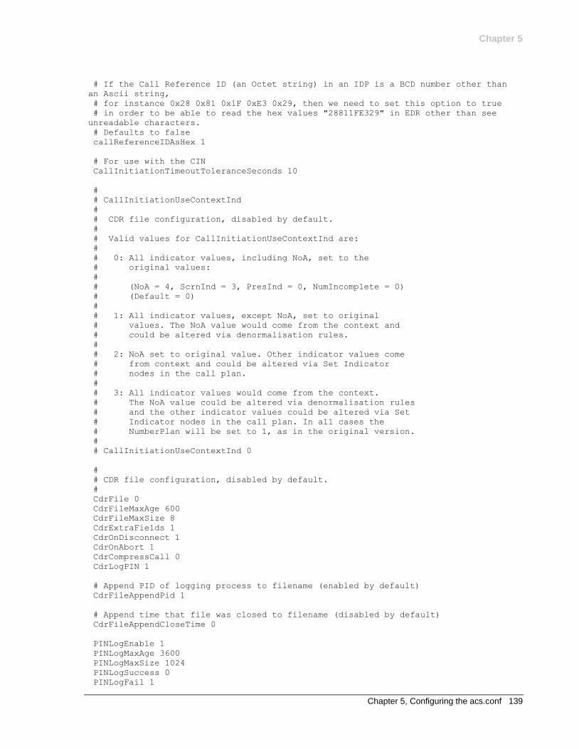
Chapter 5
Chapter 5, Configuring the acs.conf 139
# If the Call Reference ID (an Octet string) in an IDP is a BCD number other than
an Ascii string,
# for instance 0x28 0x81 0x1F 0xE3 0x29, then we need to set this option to true
# in order to be able to read the hex values "28811FE329" in EDR other than see
unreadable characters.
# Defaults to false
callReferenceIDAsHex 1
# For use with the CIN
CallInitiationTimeoutToleranceSeconds 10
#
# CallInitiationUseContextInd
#
# CDR file configuration, disabled by default.
#
# Valid values for CallInitiationUseContextInd are:
#
# 0: All indicator values, including NoA, set to the
# original values:
#
# (NoA = 4, ScrnInd = 3, PresInd = 0, NumIncomplete = 0)
# (Default = 0)
#
# 1: All indicator values, except NoA, set to original
# values. The NoA value would come from the context and
# could be altered via denormalisation rules.
#
# 2: NoA set to original value. Other indicator values come
# from context and could be altered via Set Indicator
# nodes in the call plan.
#
# 3: All indicator values would come from the context.
# The NoA value could be altered via denormalisation rules
# and the other indicator values could be altered via Set
# Indicator nodes in the call plan. In all cases the
# NumberPlan will be set to 1, as in the original version.
#
# CallInitiationUseContextInd 0
#
# CDR file configuration, disabled by default.
#
CdrFile 0
CdrFileMaxAge 600
CdrFileMaxSize 8
CdrExtraFields 1
CdrOnDisconnect 1
CdrOnAbort 1
CdrCompressCall 0
CdrLogPIN 1
# Append PID of logging process to filename (enabled by default)
CdrFileAppendPid 1
# Append time that file was closed to filename (disabled by default)
CdrFileAppendCloseTime 0
PINLogEnable 1
PINLogMaxAge 3600
PINLogMaxSize 1024
PINLogSuccess 0
PINLogFail 1
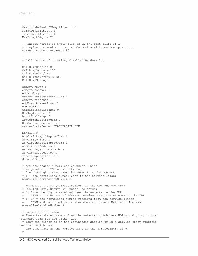
Chapter 5
140 NCC Advanced Control Services Technical Guide
OverrideDefaultIPDigitTimeout 0
FirstDigitTimeout 4
InterDigitTimeout 4
MaxPromptDigits 21
# Maximum number of bytes allowed in the text field of a
# PlayAnnouncement or PromptAndCollectUserInformation operation.
maxAnnouncementTextBytes 80
#
# Call Dump configuration, disabled by default.
#
CallDumpEnabled 0
CallDumpSeconds 120
CallDumpDir /tmp
CallDumpSeverity ERROR
CallDumpMessage
edpArmAnswer 1
edpArmNoAnswer 1
edpArmBusy 1
edpArmRouteSelectFailure 1
edpArmAbandoned 1
edpUseNoAnswerTimer 1
NokiaCIR 0
CarrierCodeDisposal 0
UseReplication 0
AuditChallenge 0
ArmTerminateTriggers 0
UseContinueOperation 0
masterStatsServer STATSMASTERNODE
SendCIR 0
AskCirAttemptElapsedTime 1
AskCirStopTime 1
AskCirConnectElapsedTime 1
AskCirCallAddress 1
usePendingTnForCaInCdr 0
AskCirReleaseCause 1
recordSmpStatistics 1
disarmEDPs 0
# set the engine's terminationNumber, which
# is printed as TN in the CDR, to:
# 0 - the digits sent over the network in the connect
# 1 - the normalised number sent to the service loader
normaliseTerminationNumber 0
# Normalise the SN (Service Number) in the CDR and set CPNN
# (Called Party Nature of Number) to match:
# 0: SN = the digits received over the network in the IDP
# CPNN = the Nature of Address received over the network in the IDP
# 1: SN = the normalised number received from the service loader
# CPNN = 0, a normalised number does not have a Nature of Address
normaliseServiceNumber 0
# Normalisation rules
# These translate numbers from the network, which have NOA and digits, into a
standard form for use within ACS.
# They can either be in the acsChassis section or in a service entry specific
section, which has
# the same name as the service name in the ServiceEntry line.
#
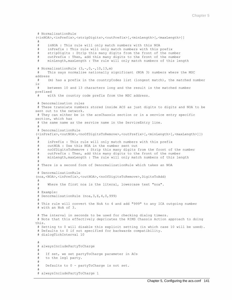
Chapter 5
Chapter 5, Configuring the acs.conf 141
# NormalisationRule
(<inNOA>,<inPrefix>,<stripDigits>,<outPrefix>[,<minLength>[,<maxLength>]]
#
# inNOA : This rule will only match numbers with this NOA
# inPrefix : This rule will only match numbers with this prefix
# stripDigits : Strip this many digits from the front of the number
# outPrefix : Then, add this many digits to the front of the number
# minLength,maxLength : The rule will only match numbers of this length
# NormalisationRule (3,-,0,-,10,13,m)
# This says normalise nationally significant (NOA 3) numbers where the MSC
address
# (m) has a prefix in the countryCodes list (longest match), the matched number
is
# between 10 and 13 characters long and the result is the matched number
prefixed
# with the country code prefix from the MSC address.
# Denormalisation rules
# These translate numbers stored inside ACS as just digits to digits and NOA to be
sent out to the network.
# They can either be in the acsChassis section or in a service entry specific
section, which has
# the same name as the service name in the ServiceEntry line.
#
# DenormalisationRule
(<inPrefix>,<outNOA>,<noOfDigitsToRemove>,<outPrefix>[,<minLength>[,<maxLength>]])
#
# inPrefix : This rule will only match numbers with this prefix
# outNOA : Use this NOA in the number sent out
# noOfDigitsToRemove : Strip this many digits from the front of the number
# outPrefix : Then, add this many digits to the front of the number
# minLength,maxLength : The rule will only match numbers of this length
#
# There is a second form of DenormalizationRule which takes an NOA
#
# DenormalisationRule
(noa,<NOA>,<inPrefix>,<outNOA>,<noOfDigitsToRemove>,DigitsToAdd)
#
# Where the first noa is the literal, lowercase text "noa".
#
# Example:
# DenormalisationRule (noa,3,E,4,0,999)
#
# This rule will convert the NoA to 4 and add "999" to any ICA outgoing number
# with an NoA of 3.
# The interval in seconds to be used for checking dialog timers.
# Note that this effectively depricates the RIMS Chassis Action approach to doing
this.
# Setting to 0 will disable this explicit setting (in which case 10 will be used).
# Defaults to 0 if not specified for backwards compatibility.
# dialogTickInterval 10
#
# alwaysIncludePartyToCharge
#
# If set, we set partyToCharge parameter in ACs
# to the leg1 party.
#
# Defaults to 0 - partyToCharge is not set.
#
# alwaysIncludePartyToCharge 1
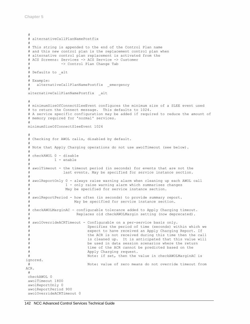
Chapter 5
142 NCC Advanced Control Services Technical Guide
#
# alternativeCallPlanNamePostfix
#
# This string is appended to the end of the Control Plan name
# and this new control plan is the replacement control plan when
# alternative control plan replacement is activated from the
# ACS Screens: Services -> ACS Service -> Customer
# -> Control Plan Change Tab
#
# Defaults to _alt
#
# Example:
# alternativeCallPlanNamePostfix _emergency
#
alternativeCallPlanNamePostfix _alt
#
# minimumSizeOfConnectSleeEvent configures the minimum size of a SLEE event used
# to return the Connect message. This defaults to 1024.
# A service specific configuration may be added if required to reduce the amount of
# memory required for 'normal' services.
#
minimumSizeOfConnectSleeEvent 1024
#
# Checking for AWOL calls, disabled by default.
#
# Note that Apply Charging operations do not use awolTimeout (see below).
#
# checkAWOL 0 - disable
# 1 - enable
#
# awolTimeout - the timeout period (in seconds) for events that are not the
# last events. May be specified for service instance section.
#
# awolReportOnly 0 - always raise warning alarm when cleaning up each AWOL call
# 1 - only raise warning alarm which summarises changes
# May be specified for service instance section.
#
# awolReportPeriod - how often (in seconds) to provide summary report.
# May be specified for service instance section.
#
# checkAWOLMarginAC - configurable tolerance added to Apply Charging timeout.
# Replaces old checkAWOLMargin setting (now deprecated).
#
# awolOverrideACRTimeout - Configurable on a per-service basis only.
# Specifies the period of time (seconds) within which we
# expect to have received an Apply Charging Report. If
# the ACR is not received during this time then the call
# is cleaned up. It is anticipated that this value will
# be used in data session scenarios where the return
# time of the ACR cannot be predicted based on the
# Apply Charging request.
# Note: if set, then the value in checkAWOLMarginAC is
ignored.
# Note: value of zero means do not override timeout from
ACR.
#
checkAWOL 0
awolTimeout 1800
awolReportOnly 0
awolReportPeriod 900
awolOverrideACRTimeout 0
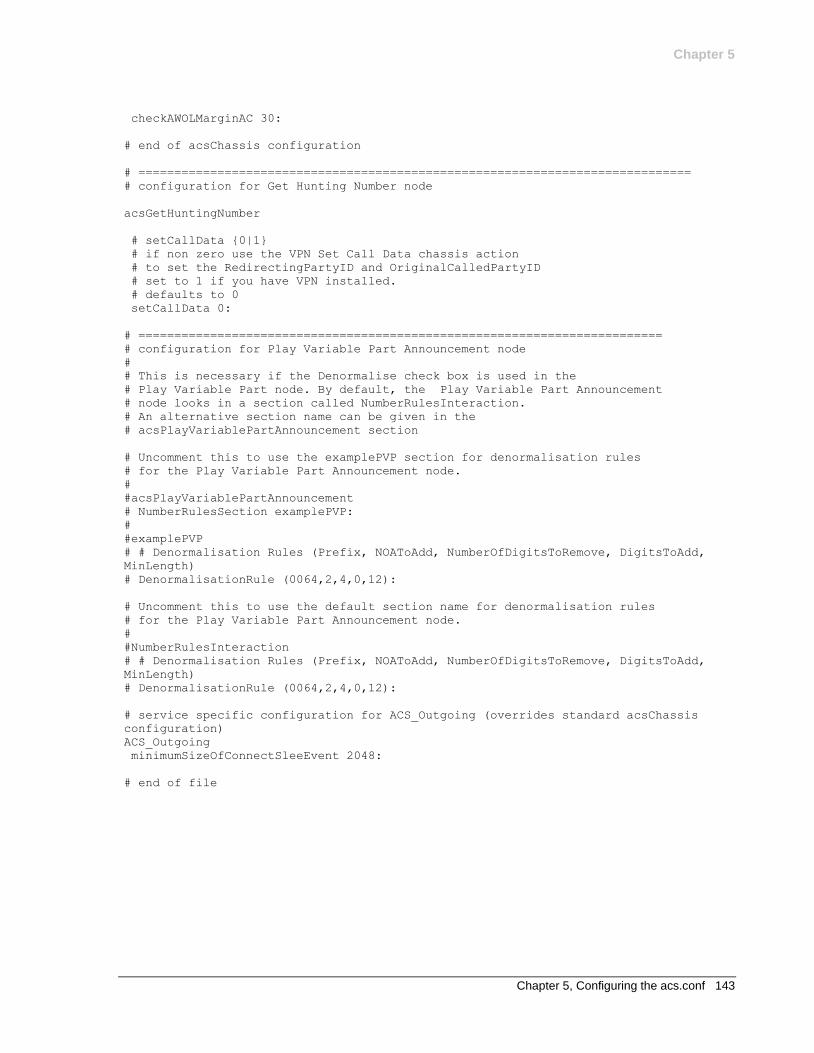
Chapter 5
Chapter 5, Configuring the acs.conf 143
checkAWOLMarginAC 30:
# end of acsChassis configuration
# =============================================================================
# configuration for Get Hunting Number node
acsGetHuntingNumber
# setCallData {0|1}
# if non zero use the VPN Set Call Data chassis action
# to set the RedirectingPartyID and OriginalCalledPartyID
# set to 1 if you have VPN installed.
# defaults to 0
setCallData 0:
# =========================================================================
# configuration for Play Variable Part Announcement node
#
# This is necessary if the Denormalise check box is used in the
# Play Variable Part node. By default, the Play Variable Part Announcement
# node looks in a section called NumberRulesInteraction.
# An alternative section name can be given in the
# acsPlayVariablePartAnnouncement section
# Uncomment this to use the examplePVP section for denormalisation rules
# for the Play Variable Part Announcement node.
#
#acsPlayVariablePartAnnouncement
# NumberRulesSection examplePVP:
#
#examplePVP
# # Denormalisation Rules (Prefix, NOAToAdd, NumberOfDigitsToRemove, DigitsToAdd,
MinLength)
# DenormalisationRule (0064,2,4,0,12):
# Uncomment this to use the default section name for denormalisation rules
# for the Play Variable Part Announcement node.
#
#NumberRulesInteraction
# # Denormalisation Rules (Prefix, NOAToAdd, NumberOfDigitsToRemove, DigitsToAdd,
MinLength)
# DenormalisationRule (0064,2,4,0,12):
# service specific configuration for ACS_Outgoing (overrides standard acsChassis
configuration)
ACS_Outgoing
minimumSizeOfConnectSleeEvent 2048:
# end of file

Chapter 6, Background Processes 145
Chapter 6
Background Processes
Overview
Introduction
This chapter explains how to manage the ACS processes.
Purpose
The chapter lists the ACS processes which execute on an installed ACS platform. These processes are a combination of inittab processes, and cron processes.
Important: It is a prerequisite for managing these core service functions that the operator is familiar with the basics of Unix process scheduling and management. Specifically, the following Unix commands:
init (and inittab)
cron (and crontab)
ps
kill
In this chapter
This chapter contains the following topics.
Automated ACS Processes (SMS Machine) 145 acsCompilerDaemon 146 acsSnCpActAlarms 147 acsDbCleanup.sh 149 acsProfileCompiler 149 acsStatisticsDBInserter 150 smsLogCleaner 151 Automated ACS Processes (SLC Machine) 152 acsStatsMaster 152 libacsChassisActions 153 libacsMacroNodes 153 libacsService 153
Automated ACS Processes (SMS Machine)
Introduction
The acsSmp package installs three tasks into the /etc/inittab. These tasks should be running at all times. The tasks are:
acsCompilerDaemon
acsStatisticsDBInserter
acsProfileCompiler
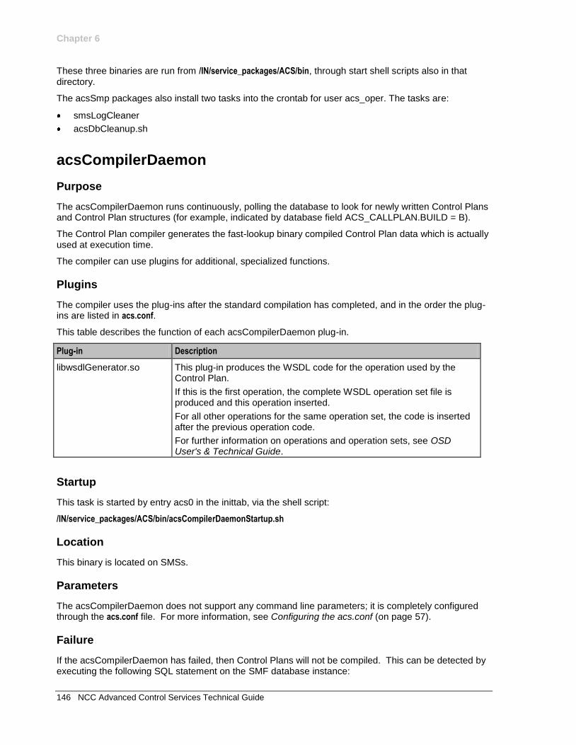
Chapter 6
146 NCC Advanced Control Services Technical Guide
These three binaries are run from /IN/service_packages/ACS/bin, through start shell scripts also in that directory.
The acsSmp packages also install two tasks into the crontab for user acs_oper. The tasks are:
smsLogCleaner
acsDbCleanup.sh
acsCompilerDaemon
Purpose
The acsCompilerDaemon runs continuously, polling the database to look for newly written Control Plans and Control Plan structures (for example, indicated by database field ACS_CALLPLAN.BUILD = B).
The Control Plan compiler generates the fast-lookup binary compiled Control Plan data which is actually used at execution time.
The compiler can use plugins for additional, specialized functions.
Plugins
The compiler uses the plug-ins after the standard compilation has completed, and in the order the plug-ins are listed in acs.conf.
This table describes the function of each acsCompilerDaemon plug-in.
Plug-in Description
libwsdlGenerator.so This plug-in produces the WSDL code for the operation used by the Control Plan.
If this is the first operation, the complete WSDL operation set file is produced and this operation inserted.
For all other operations for the same operation set, the code is inserted after the previous operation code.
For further information on operations and operation sets, see OSD User's & Technical Guide.
Startup
This task is started by entry acs0 in the inittab, via the shell script:
/IN/service_packages/ACS/bin/acsCompilerDaemonStartup.sh
Location
This binary is located on SMSs.
Parameters
The acsCompilerDaemon does not support any command line parameters; it is completely configured through the acs.conf file. For more information, see Configuring the acs.conf (on page 57).
Failure
If the acsCompilerDaemon has failed, then Control Plans will not be compiled. This can be detected by executing the following SQL statement on the SMF database instance:
Chapter 6
Chapter 6, Background Processes 147
SELECT ID from ACS_CALL_PLAN where BUILD='B';
Under normal operation, Control Plans will only remain in the B state for a few seconds at most.
Output
The acsCompilerDaemon writes error messages to the system messages file, and also writes additional output to:
/IN/service_packages/ACS/tmp/acsCompilerDaemon.log
acsSnCpActAlarms
Purpose
acsSnCpActAlarms queries the ACS_SN_CALL_PLAN_ACTIVATION database table and generates alarms when it finds any scheduled control plans that have been temporarily disabled by Emergency Control Plan Activation.
Location
This binary is located on SMSs.
Startup
This task is run in the crontab for acs_oper.
/IN/service_packages/ACS/bin/acsSnCpActAlarms
Note: You may optionally write a shell script (to manually start) if you wish to change defaults.
Parameters
The acsSnCpActAlarms does not support any command line parameters. It is configured through the eserv.config file.
eserv.config parameters
Here is an example of the acsSnCpActAlarms section in the eserv.config file.
acsSnCpActAlarms = {
oracleUserIdPassword = "/"
alarmCheckInterval = 60
repeatAlarm = false
serviceNumberTerm = "Service Number"
alarmReason = "by Alternative Control Plan Activation"
}
oracleUserIdPassword
Syntax: oracleUserIdPassword = "user/pw"
Description: The Oracle user ID and password that acsSnCpActAlarms uses to log into the database.
Type: String
Optionality: Optional (default used if not set).
Allowed:
Default: "/"
Chapter 6
148 NCC Advanced Control Services Technical Guide
Notes:
Example: oracleUserIdPassword = "/"
alarmCheckInterval
Syntax: alarmCheckInterval = mins
Description: Alarms will be generated if the difference between the current time and the control plan's Effective Date (being in the past) is less than the value specified by this parameter.
Type: Integer
Optionality: Optional (default used if not set).
Allowed:
Default: 60
Notes: Set this value to a similar/compatible value when running acsSnCpActAlarms from crontab. For example, if crontab is set up to run this process every hour, set this value to 60 minutes.
Warning: Running this process too frequently from crontab may adversely affect system performance. The recommended crontab configuration is to run this process every hour or at a greater interval.
Example: alarmCheckInterval = 60
repeatAlarm
Syntax: repeatAlarm = true|false
Description: If set to true, relevant alarm(s) will be repeated every alarmCheckInterval minutes until alternative control plan replacement is deactivated.
Type: Boolean
Optionality: Optional (default used if not set).
Allowed:
Default: false
Notes:
Example: repeatAlarm = false
serviceNumberTerm
Syntax: serviceNumberTerm = "snterm"
Description: The preferred term used to describe a Service Number.
Type: String
Optionality: Optional (default used if not set).
Allowed:
Default: "Service Number"
Notes:
Example: serviceNumberTerm = "Freephone Number"
alarmReason
Syntax: alarmReason = "reason"
Description: The reason the alarm is generated. This text is used in the alarm description.
Type: String
Optionality: Optional (default used if not set).
Chapter 6
Chapter 6, Background Processes 149
Allowed:
Default: "by Alternative Control Plan Activation"
Notes: Example alarm:
If serviceNumberTerm = "Freephone Number" and alarmReason = "by Emergency Control Plan Activation", then the alarm description would be:
"WARNING: Scheduled Control Plan(Name) for Customer(Name), Freephone Number(123) has been temporary disabled by Emergency Control Plan Activation"
Example: alarmReason = "by Alternative Control Plan Activation"
acsDbCleanup.sh
Purpose
This task executes SQL statements to delete old data from the ACS Event Counter table ACS_STATISTICS_COUNT, and also to delete old compiler output from the ACS_COMPILE_ERRORS table.
Startup
This task is run in the crontab for acs_oper, by default at 02:00 local system time. It is a shell script, specifically /IN/service_packages/ACS/bin/acsDbCleanup.sh.
Location
This binary is located on SMSs.
Parameters
The purge-age in days is defined inside the shell script itself, and can be adjusted, subject to limitations of table space in the database.
Failure
If this process is not running, old entries in the specified tables will not be purged.
Output
The acsDbCleanup.sh script writes output to:
/IN/service_packages/ACS/tmp/acsDbCleanup.sh.log
acsProfileCompiler
Purpose
The acsProfileCompiler polls for changes in the timezone and/or termination number ranges configured in the database. It then performs changes in the global profile, and in customer profiles for customers who have non-default termination ranges defined.
Chapter 6
150 NCC Advanced Control Services Technical Guide
Startup
This task is started by entry acs2 in the inittab, through the /IN/service_packages/ACS/bin/acsProfileCompilerStartup.sh shell script.
Location
This binary is located on SMSs.
Parameters
The acsProfileCompiler does not support any command line parameters, it is completely configured via the acs.conf file. For more information, see Configuring the acs.conf (on page 57).
Failure
If the process fails, then changes to the ACS timezone geography set will not be reflected on the SLC call-processing. Similarly, changes to the self-management Control Plan.
Note: The termination number constraints for ACS GUI changes will continue to operate as expected.
Output
The acsProfileCompiler writes error messages to the system messages file, and also writes additional output to:
/IN/service_packages/ACS/tmp/acsProfileCompiler.log
acsStatisticsDBInserter
Purpose
The acsStatisticsDBInserter communicates with the acsStatsMaster process (see below), and polls for changes to ACS Event Counters.
Note: This process is not the same as the smsStatsDaemon, although the names are similar.
Startup
This task is started by entry acs1 in the inittab, through the /IN/service_packages/ACS/bin/acsStatisticsDBInserterStartup.sh shell script.
Location
This binary is located on SMSs.
Parameters
The acsStatisticsDBInserter supports the following command-line options:
Usage:
acsStatisticsDBInserter -h hostname -p port -s sleep
Chapter 6
Chapter 6, Background Processes 151
These options can be used for testing to override the values specified in the
acsStatisticsDBInserter section of the acs.conf, however they should not be required on an
operational platform.
Parameter Default Description
-h hostname
-p port
-s sleep
Failure
This process will periodically write updated Event Counts to the ACS database, into the table ACS_STATISTICS_COUNT. If there are no Event Counts being modified by active Control Plans, the this process may appear to be inactive.
Failure of this process will result in no updates to the ACS_STATISTICS_COUNT table, even when EventCounting nodes are encountered in active Control Plans.
Output
The acsStatisticsDBInserter writes error messages to the system messages file, and also writes additional output to /IN/service_packages/ACS/tmp/acsStatisticsDBInserter.log.
smsLogCleaner
Purpose
The log cleaner looks for old/large log files in /IN/service_packages/ACS/tmp, and moves them into the archive subdirectory. Old files in that subdirectory are purged.
Startup
This task is run in the crontab for acs_oper. By default, it runs at 35 minutes past each hour. It is run through the /IN/service_packages/ACS/bin/acsLogCleanerStartup.sh shell script.
Location
This binary is located on both SLCs and SMSs.
Parameters
For more information about command line parameter description for the smsLogCleaner binary, which is installed as part of the smsSms packages, see the SMS Technical Guide.
Failure
If this process is not running, log files will accumulate n the tmp directory beyond the configured parameters for size and age.
Output
The smsLogCleaner run by acs_oper writes error messages to the system messages file, and also writes additional output to:
Chapter 6
152 NCC Advanced Control Services Technical Guide
/IN/service_packages/ACS/tmp/acsLogCleaner.log
Automated ACS Processes (SLC Machine)
Introduction
The acsScp package installs one task into the /etc/inittab for one of the SLC machines in an SLC grouping. This task should be running on that one machine at all times. The task is:
acsStatsMaster
This binary is run from /IN/service_packages/ACS/bin, via start-up shell script contained within that same directory.
The acsScp packages also install one task into the crontab for user acs_oper. The task is:
smsLogCleaner
acsStatsMaster
Purpose
The acsStatsMaster runs only on one SLC machine, typically SCP1. All other SLC nodes communicate with the master through TCP/IP to correlate their ACS event counter values.
Startup
This task is started by entry acs3 in the inittab, through the /IN/service_packages/ACS/bin/acsStatsMasterStartup.shshell script.
Location
This binary is located on SLCs.
Parameters
The acsStatsMaster does not support any command line parameters, it is completely configured through the acs.conf file. For more information, see Configuring the acs.conf (on page 57).
Failure
If the acsStatsMaster is not running, then individual nodes will not be able to correlate their event counter values. This will mean that Control Plans may perform incorrect branching. Additionally, the acsStatisticsDBInserter process will not be able to track changes to ACS Event Counter values, and there will be no updates to the corresponding table in the database.
Output
The acsStatsMaster writes error messages to the system messages file, and also writes additional output to:
/IN/service_packages/ACS/tmp/acsStatsMaster.log
Chapter 6
Chapter 6, Background Processes 153
libacsChassisActions
Purpose
libacsChassisActions provides the functions which enable the ACS Feature Nodes to interact with other elements in the system, including:
SLEE interfaces (such as TCAP IF), and
other elements on the network (such as the VPU).
Startup
If libacsChassisActions is included in the acs.conf, libacsChassisActions will be available to slee_acs when the SLEE is started.
For more information about how this included in acs.conf, see ChassisPlugin (on page 61).
Configuration
libacsChassisActions is configured by parameters in the acsChassis section of acs.conf. For more information, see Configuring the acs.conf (on page 57).
libacsMacroNodes
Purpose
This slee_acs plug-in library provides the base ACS feature nodes. For more information about the feature nodes provided by this library, see CPE User's Guide.
Startup
If libacsMacroNodes is included in the acs.conf, libacsMacroNodes will be available to slee_acs when the SLEE is started.
For more information about how this included in acs.conf, see MacroNodePluginFile (on page 61).
Configuration
libacsMacroNodes accepts the parameters from acs.conf. For more information about the available configuration, see:
Get Hunting Number Node Configuration (on page 135), and
Play Variable Part Announcement Configuration (see "Play Variable Part Announcement Node Configuration" on page 135).
libacsService
Purpose
libacsService is the ACS service library plug-in for slee_acs which handles initial set up of control plans. Based on the incoming call details, it loads up the relevant control plan and feature nodes.
Note: If other applications are installed, they may provide their own service libraries which will be used instead of libacsService.
Chapter 6
154 NCC Advanced Control Services Technical Guide
Startup
If libacsService is configured in acs.conf, it is made available to slee_acs when slee_acs is initialised. It is included in the acsChassis section of acs.conf in a ServiceEntry.
acsChassis
ServiceEntry (ACS,libacsService.so)
For more information about this configuration, see ServiceEntry - acschassis (see "acsChassis ServiceEntry Configuration (SLC)" on page 102).
Configuration
libacsService supports parameters from acs.conf. For more information, see Configuring the acs.conf (on page 57).
Chapter 7, Tools and Utilities 155
Chapter 7
Tools and Utilities
Overview
Introduction
This chapter explains the tools and utilities available in ACS.
In this chapter
This chapter contains the following topics.
acsAddCallPlan 155 acsAddCustomer 156 acsAddGeography 158 acsAddServiceNumber 158 acsDecompile 159 acsDumpControlPlan 160 acsMonitorCompiler 161 acsScheduleCallPlan 161 acsSetupAnnouncement 162 numberDataImport 162
acsAddCallPlan
Purpose
Use the acsAddCallPlan tool to import a control plan, defined in a .cpl text file, into the SMF database on either the same platform, or a different platform. For example, you can export a control plan from one platform by using acsDumpControlPlan (on page 160) and import the previously exported control plan into a different platform by using acsAddCallPlan.
The java shell script for acsAddCallPlan is located on SMS nodes. It launches a Java command line class that reuses the CPE code to achieve its requirements.
Configuration
acsAddCallPlan accepts the following parameters.
Usage:
acsAddCallPlan –u usr/pwd [-v] [-D directory [-O directory] -C acs_customer]
The available parameters are:
Parameter Default Description
-u usr/pwd username/ password. Username must be screens user credentials or SMF database user.
-v off Verbose (optional)
-D ignored Specify the directory containing the .cpl files to import (optional).
Chapter 7
156 NCC Advanced Control Services Technical Guide
Parameter Default Description
-O ignored Specify the directory to move successfully imported files to
(optional, only relevant with -D). Any files that fail to import will
not be moved.
-C ignored Specify the ACS customer that will own the imported control plans
(mandatory if -D is used).
When -D option is absent, records are added by stdin lines in the following format:
-c name -f file [-s name]|[-t name] [-d name] [-m ID] [-p]
Where the record content is:
Field Description
-c name Customer name.
-f file Exported control plan file name.
-s name New template name (optional).
Tip: This is used when there is no existing template.
-t name Existing template name (optional).
-d name New control plan name (optional).
-m ID MF Identifier for the control plan (optional).
-p Make inserted control plan public (optional).
When -D option is present, records are added in the following format for each .cpl file:
-c cust_name -f cpl_file -s cpl_name -d cpl_name
Where the record content is:
Field Description
-c cust_name Customer name is taken from the -C option argument.
-f cpl_file Is the filename of each .cpl file in the directory from the -D argument.
-s cpl_name Is the cpl file basename with the .cpl extension removed.
-d cpl_name Is the cpl file basename with the .cpl extension removed.
The control plan text file format is the same as that used for an exported control plan.
Imported control plans will be set private and mf_identifier will be set NULL.
acsAddCustomer
Purpose
Inserts a customer record into the SMF database.
Location
This binary is located on SMSs.
Configuration
acsAddCustomer accepts the following parameters.
Usage:
acsAddCallPlan –u usr/pwd [-v]
Chapter 7
Chapter 7, Tools and Utilities 157
The available parameters are:
Parameter Default Description
–u usr/pwd username/password. Username must be acs_admin.
[-v] off Verbose
Records are added by stdin lines in the following format:
-c name [-f set] [-y set] [-g set] [-n set] [-m] [-r ref] [-d desc] [-l usr] [-o
val=options] [-t policy]
Where the record content is:
Field Default Description
-c name Customer name (optional).
-f set Feature node set name (optional).
-y set Holiday set name (optional).
-g set Geography set name (optional).
-n set Announcement set name (optional).
-m Customer is Telco managed (optional).
-r ref Customer reference (optional).
-d desc Customer description (optional).
-l usr User name to be added for this customer (optional).
-o val=options Resource limits for customer (optional).
Options are:
eventlogs
statscounters
nodesinplan
callplans
callplanstructures
announcementsets
announcemententries
holidaysets
holidayentries
geographysets
geographyentries
users
-t policy global Termination number range rules (optional).
Options are:
private (own range)
global (default checking)
any (no checking)
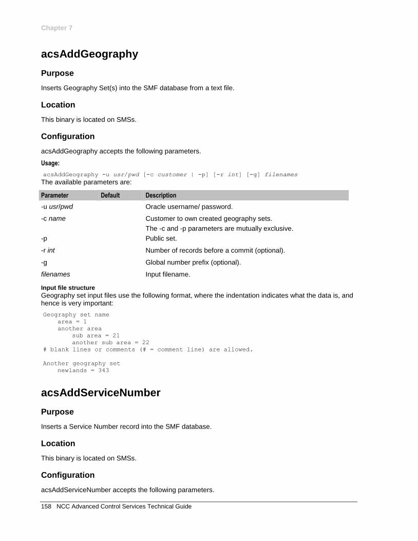
Chapter 7
158 NCC Advanced Control Services Technical Guide
acsAddGeography
Purpose
Inserts Geography Set(s) into the SMF database from a text file.
Location
This binary is located on SMSs.
Configuration
acsAddGeography accepts the following parameters.
Usage:
acsAddGeography -u usr/pwd [-c customer | -p] [-r int] [-g] filenames
The available parameters are:
Parameter Default Description
-u usr/pwd Oracle username/ password.
-c name Customer to own created geography sets.
The -c and -p parameters are mutually exclusive.
-p Public set.
-r int Number of records before a commit (optional).
-g Global number prefix (optional).
filenames Input filename.
Input file structure
Geography set input files use the following format, where the indentation indicates what the data is, and hence is very important:
Geography set name
area = 1
another area
sub area = 21
another sub area = 22
# blank lines or comments (# = comment line) are allowed.
Another geography set
newlands = 343
acsAddServiceNumber
Purpose
Inserts a Service Number record into the SMF database.
Location
This binary is located on SMSs.
Configuration
acsAddServiceNumber accepts the following parameters.
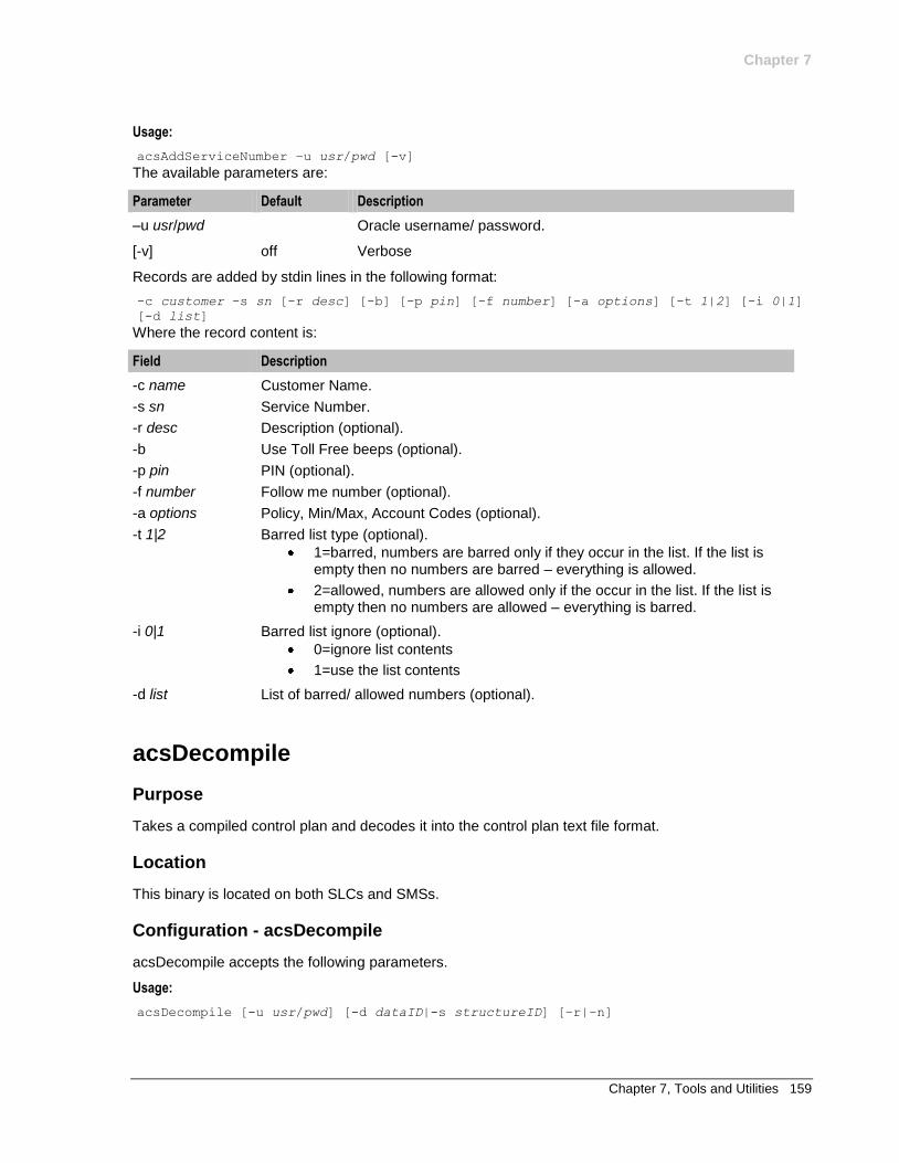
Chapter 7
Chapter 7, Tools and Utilities 159
Usage:
acsAddServiceNumber –u usr/pwd [-v]
The available parameters are:
Parameter Default Description
–u usr/pwd Oracle username/ password.
[-v] off Verbose
Records are added by stdin lines in the following format:
-c customer -s sn [-r desc] [-b] [-p pin] [-f number] [-a options] [-t 1|2] [-i 0|1]
[-d list]
Where the record content is:
Field Description
-c name Customer Name.
-s sn Service Number.
-r desc Description (optional).
-b Use Toll Free beeps (optional).
-p pin PIN (optional).
-f number Follow me number (optional).
-a options Policy, Min/Max, Account Codes (optional).
-t 1|2 Barred list type (optional).
1=barred, numbers are barred only if they occur in the list. If the list is empty then no numbers are barred – everything is allowed.
2=allowed, numbers are allowed only if the occur in the list. If the list is empty then no numbers are allowed – everything is barred.
-i 0|1 Barred list ignore (optional).
0=ignore list contents
1=use the list contents
-d list List of barred/ allowed numbers (optional).
acsDecompile
Purpose
Takes a compiled control plan and decodes it into the control plan text file format.
Location
This binary is located on both SLCs and SMSs.
Configuration - acsDecompile
acsDecompile accepts the following parameters.
Usage:
acsDecompile [-u usr/pwd] [-d dataID|-s structureID] [–r|–n]
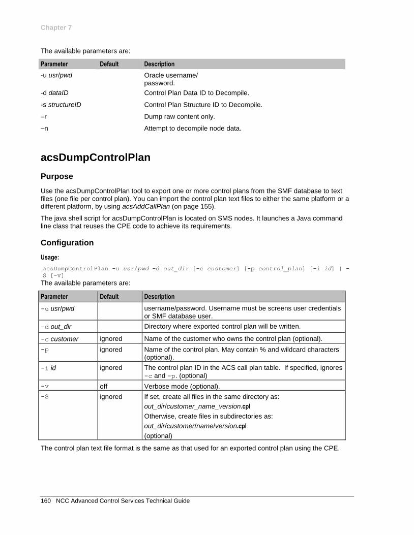
Chapter 7
160 NCC Advanced Control Services Technical Guide
The available parameters are:
Parameter Default Description
-u usr/pwd Oracle username/ password.
-d dataID Control Plan Data ID to Decompile.
-s structureID Control Plan Structure ID to Decompile.
–r Dump raw content only.
–n Attempt to decompile node data.
acsDumpControlPlan
Purpose
Use the acsDumpControlPlan tool to export one or more control plans from the SMF database to text files (one file per control plan). You can import the control plan text files to either the same platform or a different platform, by using acsAddCallPlan (on page 155).
The java shell script for acsDumpControlPlan is located on SMS nodes. It launches a Java command line class that reuses the CPE code to achieve its requirements.
Configuration
Usage:
acsDumpControlPlan -u usr/pwd -d out_dir [-c customer] [-p control_plan] [-i id] | -
S [–v]
The available parameters are:
Parameter Default Description
-u usr/pwd username/password. Username must be screens user credentials or SMF database user.
-d out_dir Directory where exported control plan will be written.
-c customer ignored Name of the customer who owns the control plan (optional).
-p ignored Name of the control plan. May contain % and wildcard characters (optional).
-i id ignored The control plan ID in the ACS call plan table. If specified, ignores
-c and -p. (optional)
-v off Verbose mode (optional).
-S ignored If set, create all files in the same directory as:
out_dir/customer_name_version.cpl
Otherwise, create files in subdirectories as:
out_dir/customer/name/version.cpl
(optional)
The control plan text file format is the same as that used for an exported control plan using the CPE.
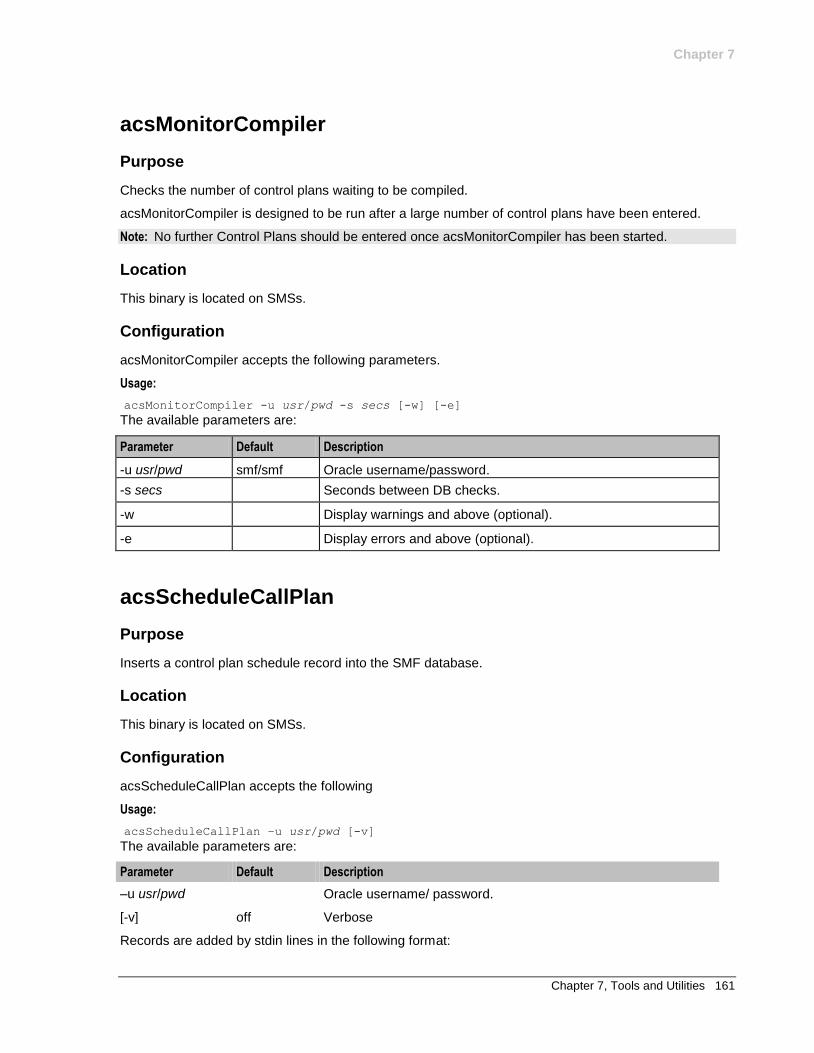
Chapter 7
Chapter 7, Tools and Utilities 161
acsMonitorCompiler
Purpose
Checks the number of control plans waiting to be compiled.
acsMonitorCompiler is designed to be run after a large number of control plans have been entered.
Note: No further Control Plans should be entered once acsMonitorCompiler has been started.
Location
This binary is located on SMSs.
Configuration
acsMonitorCompiler accepts the following parameters.
Usage:
acsMonitorCompiler -u usr/pwd -s secs [-w] [-e]
The available parameters are:
Parameter Default Description
-u usr/pwd smf/smf Oracle username/password.
-s secs Seconds between DB checks.
-w Display warnings and above (optional).
-e Display errors and above (optional).
acsScheduleCallPlan
Purpose
Inserts a control plan schedule record into the SMF database.
Location
This binary is located on SMSs.
Configuration
acsScheduleCallPlan accepts the following
Usage:
acsScheduleCallPlan –u usr/pwd [-v]
The available parameters are:
Parameter Default Description
–u usr/pwd Oracle username/ password.
[-v] off Verbose
Records are added by stdin lines in the following format:
Chapter 7
162 NCC Advanced Control Services Technical Guide
-c name -s sn -p name -d YYYYMMDD24MMSS [-a]
Where the record content is:
Field Description
-c name Customer Name.
-s sn Service Number.
-p name Control Plan name.
-d list Schedule time.
-a Activate against CLI not SN. (optional).
acsSetupAnnouncement
Purpose
Inserts an announcement record into the SMF database.
Location
This binary is located on SMSs.
Configuration
acsSetupAnnouncement accepts the following parameters.
Usage:
acsSetupAnnouncement [-u usr/pwd] [-l lang] -s set -e entry -r srf -i id [-c name]
[-v] [-n] [-g time] [-d desc]
The available parameters are:
Parameter Description
-u usr/pwd Oracle username/ password (optional).
-l lang Language name (optional).
-s set Set name.
-e entry Entry name.
-r srf srf name.
-i id Numeric announcement ID.
-c name Customer name (optional). If not set, the Announcement Set will be public.
-v Verbose (optional).
-n No SMS security challenge (optional).
-g time Generate script to run this tool to create same mappings (optional).
-d desc Announcement description (optional).
numberDataImport
Purpose
The numberDataImport tool enables you to create and update table lookup datasets from a comma separated value (CSV) file.
Chapter 7
Chapter 7, Tools and Utilities 163
You can create any number of table lookup datasets. Each table lookup dataset contains a group of related codes and prefix mappings. For example, you can create a table lookup dataset for a specific geographic area or suburb.
A table lookup dataset can be public or private. A private table lookup dataset belongs to a specific customer. It is only available to that customer and the parent customers linked to that customer in the customer hierarchy. A public table lookup dataset is available to all customers.
The numberDataImport tool is located here:
/IN/service_packages/ACS/bin
Before running numberDataImport, you must do the following:
Configure the numberDataImport tool in the eserv.config file. See Configuring the numberDataImport Tool (on page 163).
Create the CSV input file for the numberDataImport tool. See Creating the Dataset Input File (on page 163).
To run numberDataImport, see Creating and Updating Table Lookup Datasets (on page 164).
After creating Table Lookup Datasets, you can use them in the Table Lookup feature node configurations. For information about configuring the Table Lookup feature node, see NCC Feature Nodes Reference Guide.
You can search table lookup datasets for a prefix number or a mapping code using the ACS UI. For more information, see the discussion on configuring ACS in NCC Advanced Control Services User's Guide.
Configuring the numberDataImport Tool
You configure numberDataImport in the NumberMappingImport section of the eserv.config configuration
file on the SMS. The following example shows the NumberMappingImport section:
NumberMappingImport = {
closedDirectory = "closed_dir"
errorDirectory = "error_dir"
dbCommitBatchSize = size
progressDotInterval = int
}
Where:
closed_dir is the directory to which numberDataImport copies successful import files. Defaults to
/IN/service_packages/ACS/mappingData/closed if not specified.
error_dir is the directory to which numberDataImport writes import error files. Defaults to
/IN/service_packages/ACS/mappingData/error if not specified.
size sets the number of insert or update operations to perform before committing the data to the
database. There is a 10 second pause at each interval to help throttle replication. Defaults to 5000 if not specified.
int defines the number of insert or update operations to perform before displaying a progress dot
(a dot that is displayed on the console for every x number of updates). Defaults to 100 if not specified.
Creating the Dataset Input File
You import entries into a table lookup dataset from a comma-separated value (CSV) file that you create. You specify this file as input to the numberDataImport tool when you run the tool from a command line.
To create the dataset CSV file:
Step Action
1 Open a new file in a text editor.
Chapter 7
164 NCC Advanced Control Services Technical Guide
Step Action
2 Add dataset entries to the file by using the following syntax for each entry. Add each entry on a new line: a|A|d|D,lookup_code,lookup_prefix
Where:
a or A specifies to add the dataset entry. If the dataset entry already exists, it is
updated.
d or D specifies to delete the dataset entry. If the dataset entry does not exist,
this file entry is ignored.
lookup_code is the code that maps to the prefix in lookup_prefix.
lookup_prefix is a prefix number or CLI.
3 Save the file, giving it the file extension .csv.
Example CSV file entries:
a,3333,32014733
a,4444,32014744
d,5555,320147355
d,6666,320147366
Creating and Updating Table Lookup Datasets
Follow these steps to run the numberDataImport tool.
Step Action
1 Open a command shell and log in to the SMS as the acs_oper user.
2 Navigate to the /IN/service_packages/ACS/bin directory.
Chapter 7
Chapter 7, Tools and Utilities 165
Step Action
3 Run the numberDataImport tool by using the following syntax: ./numberDataImport [–F|D] –u user/password [-s dataset] [-a
acs_customer] -i filename
Where:
F and D are optional parameters that indicate whether to create or update the dataset. Specify:
F to create the dataset. If the dataset already exists then you see a warning message asking if you want to continue. If you want to overwrite the existing dataset entries, then answer Y, otherwise answer N.
D to update the specified dataset.
If you do not specify F or D and the dataset does not already exist, then numberDataImport creates a new dataset. If the dataset does exist, then it is updated.
user/password is the user and password for an ACS user with the required
user privilege level. For information on setting user privileges, see NCC Service Management System User's Guide.
dataset is an optional parameter that defines the name of the dataset that
you want to create or update. If you don't specify dataset, then the dataset
name defaults to "Default".
acs_customer is an optional parameter that defines the name of the ACS
customer the dataset belongs to. If you don't specify acs_customer, then the
dataset will be public and therefore available to all customers.
filename is the name of the CSV file that contains the dataset entries.
Note: Values for the -a, -s, and -i parameters can be quoted or unquoted. However,
you must enclose a value in quotes if it contains spaces.
For example, you could create Dataset1 for customer ABC from the entries in Dataset1.csv by running the following command: ./numberDataImport -F -u user/password -s Dataset1 -a ABC -i
Dataset1.csv
After successfully importing a dataset from a CSV file, the CSV file is moved to the following location by default:
/IN/service_packages/ACS/mappingData/closed
If the numberDataImport tool fails to import any entries, then these failed entries are written to the following error file by default:
/IN/service_packages/ACS/mappingData/error/filename.error
Where filename is the name of the csv input file.
For information about the location of the numberDataImport output files, see Configuring the numberDataImport Tool (on page 163).

Chapter 8, Pre-installation 167
Chapter 8
Pre-installation
Overview
Introduction
This chapter explains the pre-installation configuration requirements of the application.
In this chapter
This chapter contains the following topics.
ACS Client Specifications 167 Preparing the System 168
ACS Client Specifications
Specifications
This topic provides the specifications of ACS.
Network
The minimum requirements of network bandwidth for acceptable normal response times are as follows:
Number of Users Minimum Requirements
1-5 512 KB
6-15 1 MB
16 + LAN connection (at least 25% available resource of 10 MB)
Memory
This table shows the minimum Client resources required.
RAM CPU
256 MB 800 MHz
This table shows the recommended Client resources required.
RAM CPU
512 MB 1.2 GHz
Chapter 8
168 NCC Advanced Control Services Technical Guide
Response times
This table shows typical response time.
GUI Action Response Time
Startup to Login dialog 30 seconds maximum
Login to SMS main screen 20 seconds maximum
SMS main screen to ACS 5 seconds maximum
ACS main screen to CPE 15 seconds maximum
Screen
Here is the required screen specification.
Pixel
800 x 600 pixel resolution
Preparing the System
Introduction
It is recommended that you check the kernel parameters on the system to ensure the system is optimally configured.
The following parameters are described in their respective technical guides. However, they are collated here for reference.
Note: Actual kernel parameters may be greater than those listed here.
Checking Kernel parameters
Follow these steps to check the Kernel parameters for Solaris.
Step Action
1 Log in as root.
2 Enter cat /etc/system
3 Check the parameters are set to at least the minimum values.
4 Change the parameters as required using the following command from /etc/system.
Parameters
Here is a list of the Kernel parameters.
msgtql
Description: Maximum number of messages (system wide).
Allowed: Positive integer
Default: 600
msgmnb
Description: Maximum number of bytes per message queue.
Allowed: Positive integer
Chapter 8
Chapter 8, Pre-installation 169
Default: 64000
semmni
Description: Number of semaphore identifiers.
Allowed: Positive integer
Default: 100
semmsl
Description: Maximum number of semaphores per unique ID.
Allowed: Positive integer
Default: 250
semmns
Description: Maximum number of semaphores.
Allowed: Positive integer
Default: 1024
shmmax
Description: Maximum shared Mem segment (bytes).
Allowed: Positive integer
Default: 4294967295 (Hex 40000000)
shmmin
Description: Minimum shared Mem segment (bytes).
Allowed: Positive integer
Default: 1
shmmni
Description: Number of shared memory identifiers.
Allowed: Positive integer
Default: 100
shmseg
Description: Number of shared memory segments allowed per process.
Allowed: Positive integer
Default: 10
semopm
Description: Maximum number of semaphore operations that can be executed per semop system call.
Allowed: Positive integer
Default: 100

Chapter 8
170 NCC Advanced Control Services Technical Guide
semvmx
Description: Maximum semaphore value.
Allowed: Positive integer
Default: 65535

Chapter 9, About Installation and Removal 171
Chapter 9
About Installation and Removal
Overview
Introduction
This chapter provides details of the installation and removal process for the application.
In this chapter
This chapter contains the following topics.
Installation and Removal Overview 171 Installing acsSms Packages on a Clustered SMS 172 Checking the Installation 173 System Manifest 176
Installation and Removal Overview
Introduction
For information about the following requirements and tasks, see NCC Installation Guide:
NCC system requirements
Pre-installation tasks
Installing and removing NCC packages
ACS packages
An installation of ACS includes the following packages, on the:
SMS:
acsSms acsCluster (for clustered SMS)
SLC:
acsScp
VWS:
acsBe
Icons
During the acsSms installation process, you will be asked to nominate icons.
The icons referred to appear on the left hand side of each ACS window's title bar.
Chapter 9
172 NCC Advanced Control Services Technical Guide
The most commonly used icon is Java's red and white cup of coffee: . If the Java icon is chosen, ACS uses it for all windows.
Two sets of Oracle (Oracle) icons are also available. One set has blue as its dominant color; the other has orange. If you choose an Oracle icon set, ACS assigns a different icon to each ACS window.
Some of the Oracle icons look like this: .
Choosing an Oracle icon instead of the Java icon may be helpful because:
each ACS window displays a different icon, and
you can use the two color themes to identify two different systems. This makes it easy to see at a glance which windows are attached to which systems.
Installing acsSms Packages on a Clustered SMS
Raw devices
ACS can allocate tablespace storage based on raw (without a file system) partitions. This enhances the performance of ACS on the SMS.
If you are using the raw devices option, you must create the raw partitions before installing the database using tools such as the system’s format command.
The raw devices file (which you will be prompted to complete during the installation) must contain the full paths of the device files for the appropriate partitions.
The partitions must be at least as big as the required datafile sizes listed in the sizing file used by the installation.
Raw devices configuration
Follow these steps to configure raw devices.
Note: This is required only if the installation uses raw devices in place of datafiles.
Step Action
1 If your database sizing was set to large, create disk partitions of the following sizes: 1 2501 MB
2 1501 MB
3 1501 MB
For more information about the format command, see man format.
If your database sizing was set to medium, create disk partitions of the following sizes: 1 7002 MB
2 5002 MB
3 4002 MB
4 201 MB
5 101 MB
6 2 MB
For more information about the format command, see man format.
2 Edit the acs_devices.sh file specified above.
3 Change the line: ACS_DATA_DATAFILE=
to ACS_DATA_DATAFILE=/dev/did/rdsk/partition
Where:
partition is the name of the partition (for example: d8s0)
Chapter 9
Chapter 9, About Installation and Removal 173
Step Action
4 Change the line: ACS_INDEX_DATAFILE1=
to ACS_INDEX_DATAFILE1=/dev/rdsk/partition
Where:
partition is the name of the partition (for example: d8s1)
5 Change the line: ACS_INDEX_DATAFILE2=
to ACS_INDEX_DATAFILE2=/dev/rdsk/partition
Where:
partition is the name of the partition (for example: d8s2)
6 Check the device files for the new partitions are readable and writeable by the oracle user prior to commencing/continuing the installation.
Example command: chmod ugo+rw /dev/rdsk/d8s*
Example acs_devices.sh file
This is an example acs_devices.sh file.
#!/bin/sh
#
##########################################################################
# The following file is the structure required for knowledge of
# raw device utilisation.
##########################################################################
##########################################################################
# Raw device specification for datafile paths.
##########################################################################
ACS_DATA_DATAFILE=/dev/did/rdsk/d14s0
ACS_INDEX_DATAFILE1=/dev/did/rdsk/d14s1
ACS_INDEX_DATAFILE2=/dev/did/rdsk/d14s2
export ACS_DATA_DATAFILE ACS_INDEX_DATAFILE1 ACS_INDEX_DATAFILE2
##########################################################################
Checking the Installation
Introduction
Refer to these checklists to ensure that ACS has installed correctly.
The end of the package installation process specifies a script designed to check the installation just performed. They must be run from the command line.
Checklist - SMS
Follow these steps in this checklist to ensure ACS has been installed on an SMS machine correctly.
Step Action
1 Log in to SMS machine as root.
Chapter 9
174 NCC Advanced Control Services Technical Guide
Step Action
2 Check the following directory structure exists with subdirectories:
/IN/service_packages/ACS
/IN/html/Acs_Service
3 Check that directories contain subdirectories and that all are owned by:
acs_oper user (group oracle)
4 Log into the system as acs_oper.
Note: This step is to check that the acs_oper user is valid.
5 Type sqlplus /
No password is required.
Note: This step is to check that the acs_oper user has valid access to the database.
6 Ensure that the required ACS triggers have been added to the database for the SMF oracle user. To do this, execute the smsInstallCheck program with the following parameters: ~smf_oper/bin/smsInstallCheck -u smf/smf password -f
/IN/service_packages/ACS/etc/acsSms_SMF.check
Result: You should see the following output: CHECKING: This program is run with -u SMF/password.
... OK
CHECKING: Logged OraUser (SMF) has 67 valid triggers like 'ACS_%'.
... OK
Dec 29 03:39:01 cmnError(20808) NOTICE: smsInstallCheck: Passed all 2
tests.
7 Ensure that the required ACS tables have been added to the database for the ACS_ADMIN user and the required ACS processes are running. To do this, execute the smsInstallCheck program with the following parameters: ~smf_oper/bin/smsInstallCheck -u acs_admin/acs_admin password -f
/IN/service_packages/ACS/etc/acsSms_ACS_ADMIN.check
Result: You should see the following output: CHECKING: This program is run with -u ACS_ADMIN/password.
... OK
CHECKING: User acs_oper program acsStatisticsDBInserter has 1
instances.
... OK
CHECKING: User acs_oper program acsProfileCompiler has 1 instances.
... OK
CHECKING: User acs_oper program acsCompilerDaemon has 1 instances.
... OK
CHECKING: Logged OraUser (ACS_ADMIN) has 57 tables like 'ACS_%'.
... OK
CHECKING: Logged OraUser (ACS_ADMIN) has 320 valid triggers like
'ACS_%'.
... OK
Dec 29 03:45:23 cmnError(20976) NOTICE: smsInstallCheck: Passed all 6
tests.
8 Check the entries of /etc/inittab file.
Inittab Entries Reserved for ACS on SMS:
1 acs0
Chapter 9
Chapter 9, About Installation and Removal 175
Step Action
/IN/service_packages/ACS/bin/acsCompilerDaemonStartup.sh
(runs acsCompilerDaemon)
2 acs1
/IN/service_packages/ACS/bin/acsStatisticsDBInserterStartup.s
h
(runs acsStatisticsDBInserter)
3 acs2
/IN/service_packages/ACS/bin/acsProfileCompilerStartup.sh
(runs acsProfileCompiler)
9 Check that the processes listed in the process lists are running on the relevant machine. For a list of the processes which should be running, see Process list - SMS (see "Process list - SMP" on page 176).
Checklist - SLC
Follow these steps in this checklist to ensure ACS has been installed on an SLC machine correctly.
Step Action
1 Log in to SLC machine as root.
2 Check the following directory structure exists with subdirectories:
/IN/service_packages/ACS
3 Check the directory contains subdirectories and that all are owned by:
acs_oper user (group oracle)
4 Log into the system as acs_oper.
Note: This step is to check that the acs_oper user is valid.
5 Type sqlplus /
No password is required.
Note: This step is to check that the acs_oper user has valid access to the database.
6 Ensure that the required ACS triggers have been added to the database for the ACS_ADMIN oracle user. To do this, execute the smsInstallCheck program with the following parameters: ~smf_oper/bin/smsInstallCheck -n -u acs_admin/acs_admin password -f
/IN/service_packages/ACS/etc/acsScp.check
Result: You should see the following output: CHECKING: This program is run with -u ACS_ADMIN/password.
... OK
CHECKING: Logged OraUser (ACS_ADMIN) has 12 tables like 'ACS_%'.
... OK
Dec 29 04:23:37 cmnError(18133) NOTICE: smsInstallCheck: Passed all 2
tests.
7 Check the entries of following file:
/etc/inittab
Inittab Entries Reserved for ACS on SLC:
1 acs3 /IN/service_packages/ACS/bin/acsStatsMasterStartup.sh
(runs acsStatsMaster)
8 Check that the processes listed in the process lists are running on the relevant
Chapter 9
176 NCC Advanced Control Services Technical Guide
Step Action
machine. For a list of the processes which should be running, see Process list - SLC (see "Process list - SCP" on page 176).
Process list - SMP
If the application is running correctly, the following processes should be running on each SMS:
started from the inittab:
acsCompilerDaemon acsStatisticsDBInserter acsProfileCompiler
Process list - SCP
If the application is running correctly, the following processes should be running on each SLC:
started from the inittab:
acsStatsMaster
started during SLEE startup:
slee_acs
System Manifest
Introduction
Advanced Control Services (ACS) consists of several software executables and directories.
SMS packages
The ACS system on the SMS contains the following directory structure in the directory /IN/service_packages/ACS.
Directory File Description
/bin This directory contains run-time service executables and shell scripts.
acsCompilerDaemonStartup.sh Start up script.
acsStatisticsDBInserter Startup.sh
Start up script.
acsProfileCompiler Startup.sh
Start up script.
acsLogCleanerStartup.sh Start up script.
acsDbCleanup.sh Start up script.
acsAddCallPlan
acsAddCustomer
acsAddGeography
acsAddServiceNumber
acsDecompile
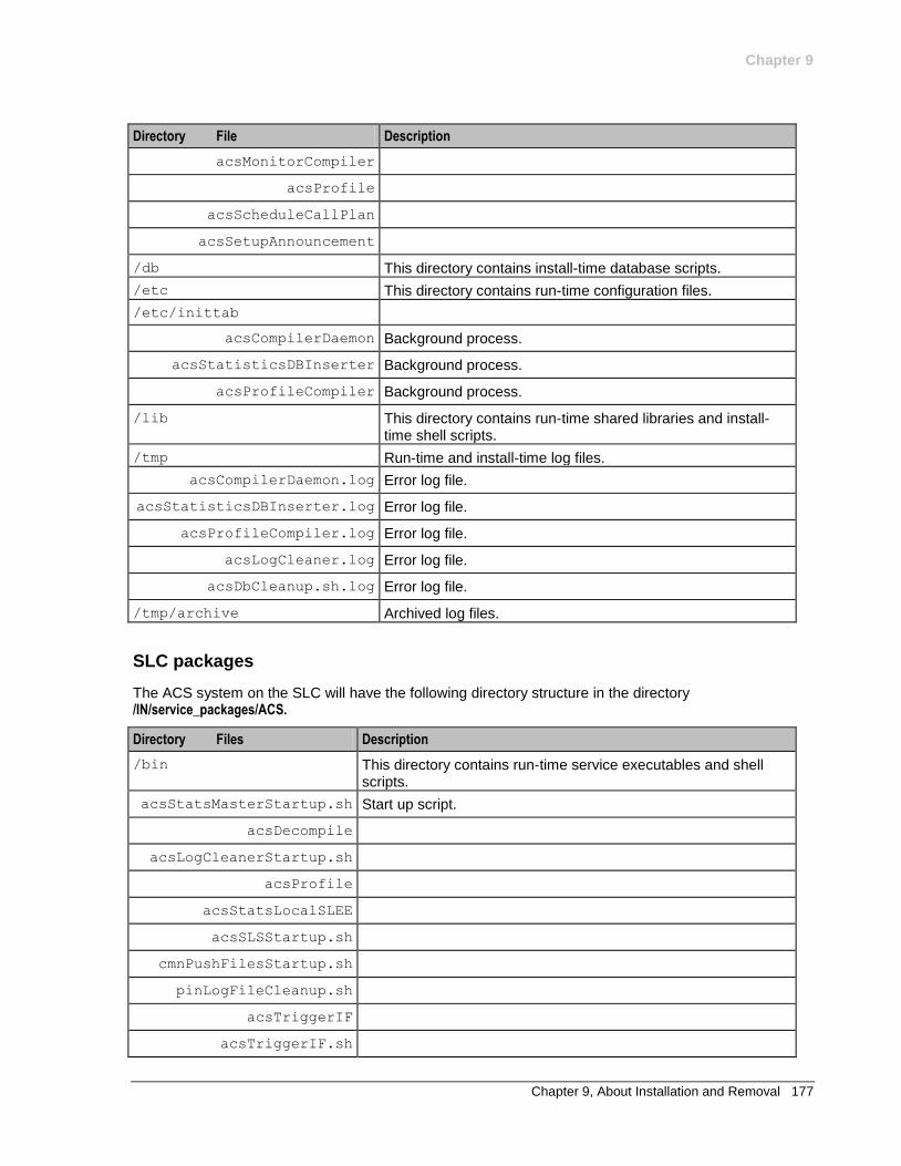
Chapter 9
Chapter 9, About Installation and Removal 177
Directory File Description
acsMonitorCompiler
acsProfile
acsScheduleCallPlan
acsSetupAnnouncement
/db This directory contains install-time database scripts.
/etc This directory contains run-time configuration files.
/etc/inittab
acsCompilerDaemon Background process.
acsStatisticsDBInserter Background process.
acsProfileCompiler Background process.
/lib This directory contains run-time shared libraries and install-time shell scripts.
/tmp Run-time and install-time log files.
acsCompilerDaemon.log Error log file.
acsStatisticsDBInserter.log Error log file.
acsProfileCompiler.log Error log file.
acsLogCleaner.log Error log file.
acsDbCleanup.sh.log Error log file.
/tmp/archive Archived log files.
SLC packages
The ACS system on the SLC will have the following directory structure in the directory /IN/service_packages/ACS.
Directory Files Description
/bin This directory contains run-time service executables and shell scripts.
acsStatsMasterStartup.sh Start up script.
acsDecompile
acsLogCleanerStartup.sh
acsProfile
acsStatsLocalSLEE
acsSLSStartup.sh
cmnPushFilesStartup.sh
pinLogFileCleanup.sh
acsTriggerIF
acsTriggerIF.sh
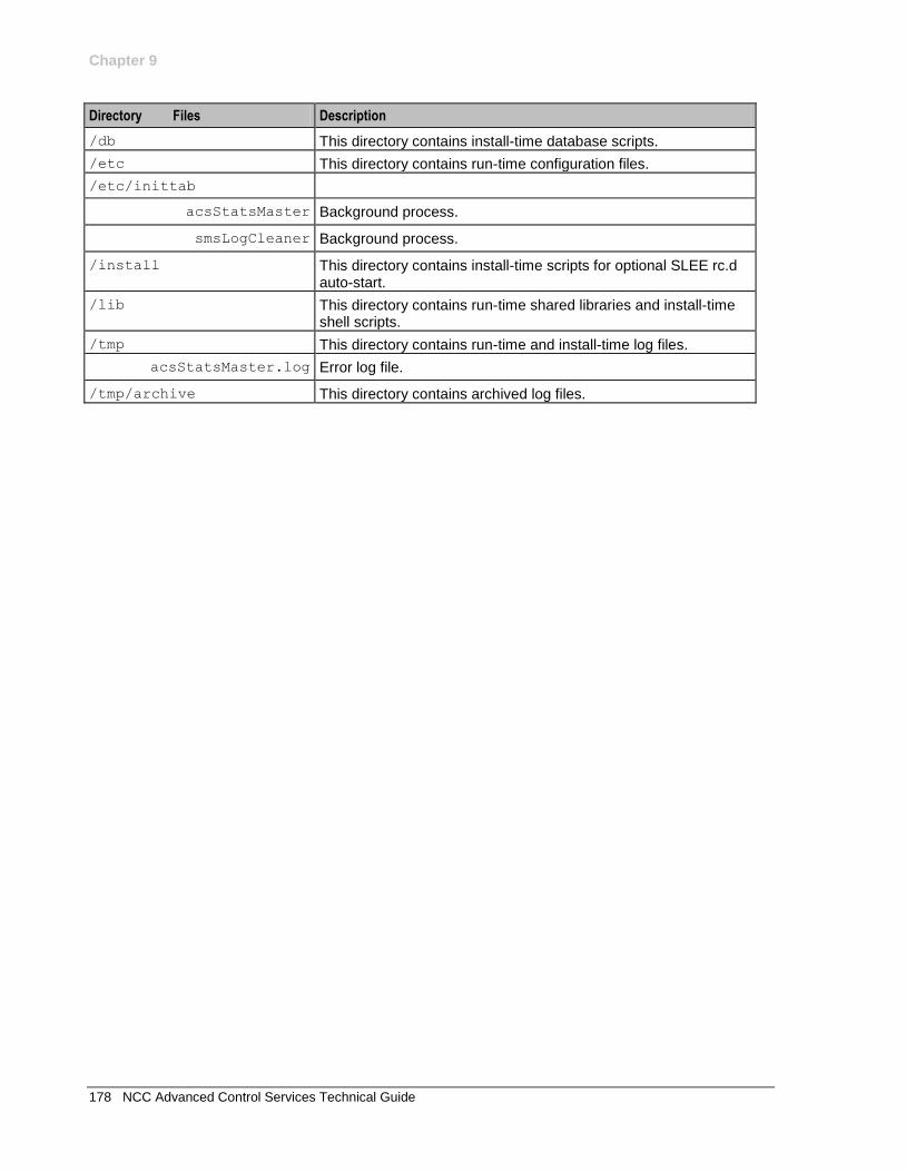
Chapter 9
178 NCC Advanced Control Services Technical Guide
Directory Files Description
/db This directory contains install-time database scripts.
/etc This directory contains run-time configuration files.
/etc/inittab
acsStatsMaster Background process.
smsLogCleaner Background process.
/install This directory contains install-time scripts for optional SLEE rc.d auto-start.
/lib This directory contains run-time shared libraries and install-time shell scripts.
/tmp This directory contains run-time and install-time log files.
acsStatsMaster.log Error log file.
/tmp/archive This directory contains archived log files.
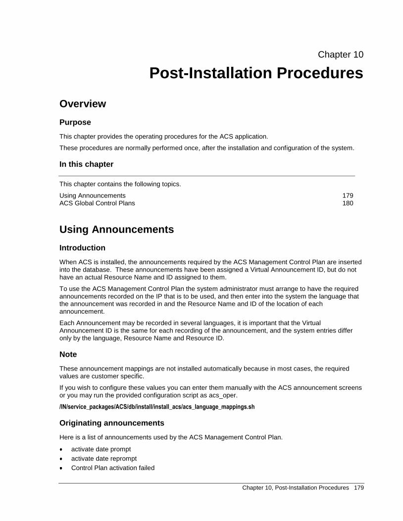
Chapter 10, Post-Installation Procedures 179
Chapter 10
Post-Installation Procedures
Overview
Purpose
This chapter provides the operating procedures for the ACS application.
These procedures are normally performed once, after the installation and configuration of the system.
In this chapter
This chapter contains the following topics.
Using Announcements 179 ACS Global Control Plans 180
Using Announcements
Introduction
When ACS is installed, the announcements required by the ACS Management Control Plan are inserted into the database. These announcements have been assigned a Virtual Announcement ID, but do not have an actual Resource Name and ID assigned to them.
To use the ACS Management Control Plan the system administrator must arrange to have the required announcements recorded on the IP that is to be used, and then enter into the system the language that the announcement was recorded in and the Resource Name and ID of the location of each announcement.
Each Announcement may be recorded in several languages, it is important that the Virtual Announcement ID is the same for each recording of the announcement, and the system entries differ only by the language, Resource Name and Resource ID.
Note
These announcement mappings are not installed automatically because in most cases, the required values are customer specific.
If you wish to configure these values you can enter them manually with the ACS announcement screens or you may run the provided configuration script as acs_oper.
/IN/service_packages/ACS/db/install/install_acs/acs_language_mappings.sh
Originating announcements
Here is a list of announcements used by the ACS Management Control Plan.
activate date prompt
activate date reprompt
Control Plan activation failed

Chapter 10
180 NCC Advanced Control Services Technical Guide
collect Control Plan ID prompt
collect Control Plan ID reprompt
collect CLI prompt
collect CLI reprompt
collect follow me number prompt
collect follow me number reprompt
collect SN prompt
collect SN reprompt
collect switch node exit number prompt
collect switch node exit number reprompt
collect switch node number prompt
collect switch node number reprompt
collected play customer message ID not allowed
follow me number not cancelled
follow me number not updated
load profile failed
load profile prompt
load profile reprompt
main menu announcement
New PIN Prompt
New PIN reprompt
PIN entry failed
PIN entry prompt
PIN entry reprompt
PIN not updated
record customer message prompt
record customer message reprompt
recorded customer message not updated
switch node CLI branch 1
switch node CLI branch 2
switch node not updated
switch node SN branch 1
switch node SN branch 2
ACS Global Control Plans
About Global Control Plans
Global control plans are an optional feature that enable the telco to apply global call-screening to calls for all customers before the customer's control plans are applied. Global control plans are automatically assigned to the default customer, and therefore they are always owned by the telco.
Global control plans are associated with a specific service entry, so that they apply only to control plans of a selected type. Service entries are defined in the acs.conf configuration file for the NCC application. You specify whether a control plan is global when you save the control plan by giving it a name that corresponds to the service to which it applies.
For more information on using global control plans, see CPE User's Guide.

Chapter 10
Chapter 10, Post-Installation Procedures 181

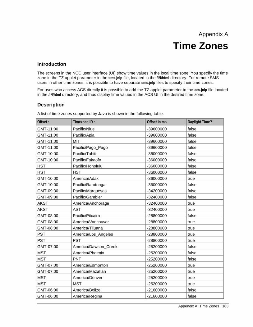
Appendix A, Time Zones 183
Appendix A
Time Zones
Introduction
The screens in the NCC user interface (UI) show time values in the local time zone. You specify the time zone in the TZ applet parameter in the sms.jnlp file, located in the /IN/html directory. For remote SMS users in other time zones, it is possible to have separate sms.jnlp files to specify their time zones.
For uses who access ACS directly it is possible to add the TZ applet parameter to the acs.jnlp file located in the /IN/html directory, and thus display time values in the ACS UI in the desired time zone.
Description
A list of time zones supported by Java is shown in the following table.
Offset : Timezone ID : Offset in ms Daylight Time?
GMT-11:00 Pacific/Niue -39600000 false
GMT-11:00 Pacific/Apia -39600000 false
GMT-11:00 MIT -39600000 false
GMT-11:00 Pacific/Pago_Pago -39600000 false
GMT-10:00 Pacific/Tahiti -36000000 false
GMT-10:00 Pacific/Fakaofo -36000000 false
HST Pacific/Honolulu -36000000 false
HST HST -36000000 false
GMT-10:00 America/Adak -36000000 true
GMT-10:00 Pacific/Rarotonga -36000000 false
GMT-09:30 Pacific/Marquesas -34200000 false
GMT-09:00 Pacific/Gambier -32400000 false
AKST America/Anchorage -32400000 true
AKST AST -32400000 true
GMT-08:00 Pacific/Pitcairn -28800000 false
GMT-08:00 America/Vancouver -28800000 true
GMT-08:00 America/Tijuana -28800000 true
PST America/Los_Angeles -28800000 true
PST PST -28800000 true
GMT-07:00 America/Dawson_Creek -25200000 false
MST America/Phoenix -25200000 false
MST PNT -25200000 false
GMT-07:00 America/Edmonton -25200000 true
GMT-07:00 America/Mazatlan -25200000 true
MST America/Denver -25200000 true
MST MST -25200000 true
GMT-06:00 America/Belize -21600000 false
GMT-06:00 America/Regina -21600000 false
184 NCC Advanced Control Services Technical Guide
Offset : Timezone ID : Offset in ms Daylight Time?
GMT-06:00 Pacific/Galapagos -21600000 false
GMT-06:00 America/Guatemala -21600000 false
GMT-06:00 America/Tegucigalpa -21600000 false
GMT-06:00 America/El_Salvador -21600000 false
GMT-06:00 America/Costa_Rica -21600000 false
GMT-06:00 America/Winnipeg -21600000 true
GMT-06:00 Pacific/Easter -21600000 true
GMT-06:00 America/Mexico_City -21600000 true
CST America/Chicago -21600000 true
CST CST -21600000 true
GMT-05:00 America/Porto_Acre -18000000 false
GMT-05:00 America/Bogota -18000000 false
GMT-05:00 America/Guayaquil -18000000 false
GMT-05:00 America/Jamaica -18000000 false
GMT-05:00 America/Cayman -18000000 false
GMT-06:00 America/Managua -21600000 false
GMT-05:00 America/Panama -18000000 false
GMT-05:00 America/Lima -18000000 false
EST America/Indianapolis -18000000 false
EST IET -18000000 false
GMT-05:00 America/Nassau -18000000 true
GMT-05:00 America/Montreal -18000000 true
GMT-05:00 America/Havana -18000000 true
GMT-05:00 America/Port-au-Prince -18000000 false
GMT-05:00 America/Grand_Turk -18000000 true
EST America/New_York -18000000 true
EST EST -18000000 true
GMT-04:00 America/Antigua -14400000 false
GMT-04:00 America/Anguilla -14400000 false
GMT-04:00 America/Curacao -14400000 false
GMT-04:00 America/Aruba -14400000 false
GMT-04:00 America/Barbados -14400000 false
GMT-04:00 America/La_Paz -14400000 false
GMT-04:00 America/Manaus -14400000 false
GMT-04:00 America/Dominica -14400000 false
GMT-04:00 America/Santo_Domingo -14400000 false
GMT-04:00 America/Grenada -14400000 false
GMT-04:00 America/Guadeloupe -14400000 false
GMT-04:00 America/Guyana -14400000 false
GMT-04:00 America/St_Kitts -14400000 false
GMT-04:00 America/St_Lucia -14400000 false
GMT-04:00 America/Martinique -14400000 false
GMT-04:00 America/Montserrat -14400000 false
Appendix A, Time Zones 185
Offset : Timezone ID : Offset in ms Daylight Time?
GMT-04:00 America/Puerto_Rico -14400000 false
GMT-04:00 PRT -14400000 false
GMT-04:00 America/Port_of_Spain -14400000 false
GMT-04:00 America/St_Vincent -14400000 false
GMT-04:00 America/Tortola -14400000 false
GMT-04:00 America/St_Thomas -14400000 false
GMT-04:00 America/Caracas -14400000 false
GMT-04:00 Antarctica/Palmer -14400000 true
GMT-04:00 Atlantic/Bermuda -14400000 true
GMT-04:00 America/Cuiaba -14400000 true
AST America/Halifax -14400000 true
GMT-04:00 Atlantic/Stanley -14400000 true
GMT-04:00 America/Thule -14400000 true
GMT-04:00 America/Asuncion -14400000 true
GMT-04:00 America/Santiago -14400000 true
NST America/St_Johns -12600000 true
NST CNT -12600000 true
GMT-03:00 America/Fortaleza -10800000 true
GMT-03:00 America/Cayenne -10800000 false
GMT-03:00 America/Paramaribo -10800000 false
GMT-03:00 America/Montevideo -10800000 false
GMT-03:00 America/Buenos_Aires -10800000 false
GMT-03:00 AGT -10800000 false
GMT-03:00 America/Godthab -10800000 true
GMT-03:00 America/Miquelon -10800000 true
GMT-03:00 America/Sao_Paulo -10800000 true
GMT-03:00 BET -10800000 true
GMT-02:00 America/Noronha -7200000 false
GMT-02:00 Atlantic/South_Georgia -7200000 false
GMT-01:00 Atlantic/Jan_Mayen -3600000 false
GMT-01:00 Atlantic/Cape_Verde -3600000 false
GMT-01:00 America/Scoresbysund -3600000 true
GMT-01:00 Atlantic/Azores -3600000 true
GMT+00:00 Africa/Ouagadougou 0 false
GMT+00:00 Africa/Abidjan 0 false
GMT+00:00 Africa/Accra 0 false
GMT+00:00 Africa/Banjul 0 false
GMT+00:00 Africa/Conakry 0 false
GMT+00:00 Africa/Bissau 0 false
GMT+00:00 Atlantic/Reykjavik 0 false
GMT+00:00 Africa/Monrovia 0 false
GMT Africa/Casablanca 0 false
GMT+00:00 Africa/Timbuktu 0 false
186 NCC Advanced Control Services Technical Guide
Offset : Timezone ID : Offset in ms Daylight Time?
GMT+00:00 Africa/Nouakchott 0 false
GMT+00:00 Atlantic/St_Helena 0 false
GMT+00:00 Africa/Freetown 0 false
GMT+00:00 Africa/Dakar 0 false
GMT+00:00 Africa/Sao_Tome 0 false
GMT+00:00 Africa/Lome 0 false
GMT GMT 0 false
GMT+00:00 UTC 0 false
GMT+00:00 Atlantic/Faeroe 0 true
GMT+00:00 Atlantic/Canary 0 true
GMT+00:00 Europe/Dublin 0 true
GMT+00:00 Europe/Lisbon 0 true
GMT+00:00 Europe/London 0 true
GMT+00:00 WET 0 true
GMT+01:00 Africa/Luanda 3600000 false
GMT+01:00 Africa/Porto-Novo 3600000 false
GMT+01:00 Africa/Bangui 3600000 false
GMT+01:00 Africa/Kinshasa 3600000 false
GMT+01:00 Africa/Douala 3600000 false
GMT+01:00 Africa/Libreville 3600000 false
GMT+01:00 Africa/Malabo 3600000 false
GMT+01:00 Africa/Niamey 3600000 false
GMT+01:00 Africa/Lagos 3600000 false
GMT+01:00 Africa/Ndjamena 3600000 false
GMT+01:00 Africa/Tunis 3600000 false
GMT+01:00 Africa/Algiers 3600000 false
GMT+01:00 Europe/Andorra 3600000 true
GMT+01:00 Europe/Tirane 3600000 true
GMT+01:00 Europe/Vienna 3600000 true
GMT+01:00 Europe/Brussels 3600000 true
GMT+01:00 Europe/Zurich 3600000 true
GMT+01:00 Europe/Prague 3600000 true
GMT+01:00 Europe/Berlin 3600000 true
GMT+01:00 Europe/Copenhagen 3600000 true
GMT+01:00 Europe/Madrid 3600000 true
GMT+01:00 Europe/Gibraltar 3600000 true
GMT+01:00 Europe/Budapest 3600000 true
GMT+01:00 Europe/Rome 3600000 true
GMT+01:00 Europe/Vaduz 3600000 true
GMT+01:00 Europe/Luxembourg 3600000 true
GMT+02:00 Africa/Tripoli 7200000 false
GMT+01:00 Europe/Monaco 3600000 true
GMT+01:00 Europe/Malta 3600000 true
Appendix A, Time Zones 187
Offset : Timezone ID : Offset in ms Daylight Time?
GMT+01:00 Africa/Windhoek 3600000 true
GMT+01:00 Europe/Amsterdam 3600000 true
GMT+01:00 Europe/Oslo 3600000 true
GMT+01:00 Europe/Warsaw 3600000 true
GMT+01:00 Europe/Stockholm 3600000 true
GMT+01:00 Europe/Belgrade 3600000 true
CET Europe/Paris 3600000 true
CET ECT 3600000 true
GMT+02:00 Africa/Bujumbura 7200000 false
GMT+02:00 Africa/Gaborone 7200000 false
GMT+02:00 Africa/Lubumbashi 7200000 false
GMT+02:00 Africa/Maseru 7200000 false
GMT+02:00 Africa/Blantyre 7200000 false
GMT+02:00 Africa/Maputo 7200000 false
GMT+02:00 Africa/Kigali 7200000 false
GMT+03:00 Africa/Khartoum 10800000 false
GMT+02:00 Africa/Mbabane 7200000 false
GMT+02:00 Africa/Lusaka 7200000 false
GMT+02:00 Africa/Harare 7200000 false
GMT+02:00 CAT 7200000 false
GMT+02:00 Africa/Johannesburg 7200000 false
GMT+02:00 Europe/Sofia 7200000 true
GMT+02:00 Europe/Minsk 7200000 true
GMT+02:00 Asia/Nicosia 7200000 true
GMT+02:00 Europe/Tallinn 7200000 false
GMT+02:00 Africa/Cairo 7200000 true
GMT+02:00 ART 7200000 true
GMT+02:00 Europe/Helsinki 7200000 true
GMT+02:00 Europe/Athens 7200000 true
IST Asia/Jerusalem 7200000 true
GMT+02:00 Asia/Amman 7200000 true
GMT+02:00 Asia/Beirut 7200000 true
GMT+02:00 Europe/Vilnius 7200000 true
GMT+02:00 Europe/Riga 7200000 false
GMT+02:00 Europe/Chisinau 7200000 true
EET Europe/Bucharest 7200000 true
GMT+02:00 Europe/Kaliningrad 7200000 true
GMT+02:00 Asia/Damascus 7200000 true
GMT+02:00 Europe/Kiev 7200000 true
GMT+02:00 Europe/Istanbul 7200000 true
GMT+02:00 EET 7200000 true
GMT+03:00 Asia/Bahrain 10800000 false
GMT+03:00 Africa/Djibouti 10800000 false
188 NCC Advanced Control Services Technical Guide
Offset : Timezone ID : Offset in ms Daylight Time?
GMT+03:00 Africa/Asmera 10800000 false
GMT+03:00 Africa/Addis_Ababa 10800000 false
GMT+03:00 EAT 10800000 false
GMT+03:00 Africa/Nairobi 10800000 false
GMT+03:00 Indian/Comoro 10800000 false
GMT+03:00 Asia/Kuwait 10800000 false
GMT+03:00 Indian/Antananarivo 10800000 false
GMT+03:00 Asia/Qatar 10800000 false
GMT+03:00 Africa/Mogadishu 10800000 false
GMT+03:00 Africa/Dar_es_Salaam 10800000 false
GMT+03:00 Africa/Kampala 10800000 false
GMT+03:00 Asia/Aden 10800000 false
GMT+03:00 Indian/Mayotte 10800000 false
GMT+03:00 Asia/Riyadh 10800000 false
GMT+03:00 Asia/Baghdad 10800000 true
GMT+02:00 Europe/Simferopol 7200000 true
GMT+03:00 Europe/Moscow 10800000 true
GMT+03:30 Asia/Tehran 12600000 true
GMT+03:30 MET 12600000 true
GMT+04:00 Asia/Dubai 14400000 false
GMT+04:00 Indian/Mauritius 14400000 false
GMT+04:00 Asia/Muscat 14400000 false
GMT+04:00 Indian/Reunion 14400000 false
GMT+04:00 Indian/Mahe 14400000 false
GMT+04:00 Asia/Yerevan 14400000 true
GMT+04:00 NET 14400000 true
GMT+04:00 Asia/Baku 14400000 true
GMT+04:00 Asia/Aqtau 14400000 true
GMT+04:00 Europe/Samara 14400000 true
GMT+04:30 Asia/Kabul 16200000 false
GMT+05:00 Indian/Kerguelen 18000000 false
GMT+04:00 Asia/Tbilisi 14400000 true
GMT+05:00 Indian/Chagos 18000000 false
GMT+05:00 Indian/Maldives 18000000 false
GMT+05:00 Asia/Dushanbe 18000000 false
GMT+05:00 Asia/Ashkhabad 18000000 false
GMT+05:00 Asia/Tashkent 18000000 false
GMT+05:00 Asia/Karachi 18000000 false
GMT+05:00 PLT 18000000 false
GMT+05:00 Asia/Bishkek 18000000 true
GMT+05:00 Asia/Aqtobe 18000000 true
GMT+05:00 Asia/Yekaterinburg 18000000 true
GMT+05:30 Asia/Calcutta 19800000 false
Appendix A, Time Zones 189
Offset : Timezone ID : Offset in ms Daylight Time?
GMT+05:30 IST 19800000 false
GMT+05:45 Asia/Katmandu 20700000 false
GMT+06:00 Antarctica/Mawson 21600000 false
GMT+06:00 Asia/Thimbu 21600000 false
GMT+06:00 Asia/Colombo 21600000 false
GMT+06:00 Asia/Dacca 21600000 false
GMT+06:00 BST 21600000 false
GMT+06:00 Asia/Almaty 21600000 true
GMT+06:00 Asia/Novosibirsk 21600000 true
GMT+06:30 Indian/Cocos 23400000 false
GMT+06:30 Asia/Rangoon 23400000 false
GMT+07:00 Indian/Christmas 25200000 false
GMT+07:00 Asia/Jakarta 25200000 false
GMT+07:00 Asia/Phnom_Penh 25200000 false
GMT+07:00 Asia/Vientiane 25200000 false
GMT+07:00 Asia/Saigon 25200000 false
GMT+07:00 VST 25200000 false
GMT+07:00 Asia/Bangkok 25200000 false
GMT+07:00 Asia/Krasnoyarsk 25200000 true
GMT+08:00 Antarctica/Casey 28800000 false
GMT+08:00 Australia/Perth 28800000 false
GMT+08:00 Asia/Brunei 28800000 false
GMT+08:00 Asia/Hong_Kong 28800000 false
GMT+08:00 Asia/Ujung_Pandang 28800000 false
GMT+08:00 Asia/Macao 28800000 false
GMT+08:00 Asia/Kuala_Lumpur 28800000 false
GMT+08:00 Asia/Manila 28800000 false
GMT+08:00 Asia/Singapore 28800000 false
GMT+08:00 Asia/Taipei 28800000 false
CST Asia/Shanghai 28800000 false
CST CTT 28800000 false
GMT+08:00 Asia/Ulan_Bator 28800000 true
GMT+08:00 Asia/Irkutsk 28800000 true
GMT+09:00 Asia/Jayapura 32400000 false
GMT+09:00 Asia/Pyongyang 32400000 false
GMT+09:00 Asia/Seoul 32400000 false
GMT+09:00 Pacific/Palau 32400000 false
JST Asia/Tokyo 32400000 false
JST JST 32400000 false
GMT+09:00 Asia/Yakutsk 32400000 true
GMT+09:30 Australia/Darwin 34200000 false
GMT+09:30 ACT 34200000 false
GMT+09:30 Australia/Adelaide 34200000 true
190 NCC Advanced Control Services Technical Guide
Offset : Timezone ID : Offset in ms Daylight Time?
GMT+09:30 Australia/Broken_Hill 34200000 true
GMT+10:00 Australia/Hobart 36000000 true
GMT+10:00 Antarctica/DumontDUrville? 36000000 false
GMT+10:00 Pacific/Truk 36000000 false
GMT+10:00 Pacific/Guam 36000000 false
GMT+10:00 Pacific/Saipan 36000000 false
GMT+10:00 Pacific/Port_Moresby 36000000 false
GMT+10:00 Australia/Brisbane 36000000 false
GMT+10:00 Asia/Vladivostok 36000000 true
GMT+10:00 Australia/Sydney 36000000 true
GMT+10:00 AET 36000000 true
GMT+10:30 Australia/Lord_Howe 37800000 true
GMT+11:00 Pacific/Ponape 39600000 false
GMT+11:00 Pacific/Efate 39600000 false
GMT+11:00 Pacific/Guadalcanal 39600000 false
GMT+11:00 SST 39600000 false
GMT+11:00 Pacific/Noumea 39600000 false
GMT+11:00 Asia/Magadan 39600000 true
GMT+11:30 Pacific/Norfolk 41400000 false
GMT+11:00 Pacific/Kosrae 39600000 false
GMT+12:00 Pacific/Tarawa 43200000 false
GMT+12:00 Pacific/Majuro 43200000 false
GMT+12:00 Pacific/Nauru 43200000 false
GMT+12:00 Pacific/Funafuti 43200000 false
GMT+12:00 Pacific/Wake 43200000 false
GMT+12:00 Pacific/Wallis 43200000 false
GMT+12:00 Pacific/Fiji 43200000 true
GMT+12:00 Antarctica/McMurdo? 43200000 true
GMT+12:00 Asia/Kamchatka 43200000 true
GMT+12:00 Pacific/Auckland 43200000 true
GMT+12:00 NST 43200000 true
GMT+12:45 Pacific/Chatham 45900000 true
GMT+13:00 Pacific/Enderbury 46800000 false
GMT+13:00 Pacific/Tongatapu 46800000 true
GMT+12:00 Asia/Anadyr 43200000 true
GMT+14:00 Pacific/Kiritimati 50400000 false
Appendix B, ASCII Codes 191
Appendix B
ASCII Codes
Description
This table shows the ASCII code values.
Decimal Octal Hex Binary Value
000 000 00 00000000 NUL (Null char.)
001 001 01 00000001 SOH (Start of Header)
002 002 02 00000010 STX (Start of Text)
003 003 03 00000011 ETX (End of Text)
004 004 04 00000100 EOT (End of Transmission)
005 005 05 00000101 ENQ (Enquiry)
006 006 06 00000110 ACK (Acknowledgment)
007 007 07 00000111 BEL (Bell)
008 010 08 00001000 BS (Backspace)
009 011 09 00001001 HT (Horizontal Tab)
010 012 0A 00001010 LF (Line Feed)
011 013 0B 00001011 VT (Vertical Tab)
012 014 0C 00001100 FF (Form Feed)
013 015 0D 00001101 CR (Carriage Return)
014 016 0E 00001110 SO (Shift Out)
015 017 0F 00001111 SI (Shift In)
016 020 10 00010000 DLE (Data Link Escape)
017 021 11 00010001 DC1 (XON) (Device Control 1)
018 022 12 00010010 DC2 (Device Control 2)
019 023 13 00010011 DC3 (XOFF)(Device Control 3)
020 024 14 00010100 DC4 (Device Control 4)
021 025 15 00010101 NAK (Negative Acknowledgment)
022 026 16 00010110 SYN (Synchronous Idle)
023 027 17 00010111 ETB (End of Trans. Block)
024 030 18 00011000 CAN (Cancel)
025 031 19 00011001 EM (End of Medium)
026 032 1A 00011010 SUB (Substitute)
027 033 1B 00011011 ESC (Escape)
028 034 1C 00011100 FS (File Separator)
029 035 1D 00011101 GS (Group Separator)
030 036 1E 00011110 RS (Request to Send) (Record Separator)
031 037 1F 00011111 US (Unit Separator)
032 040 20 00100000 SP (Space)
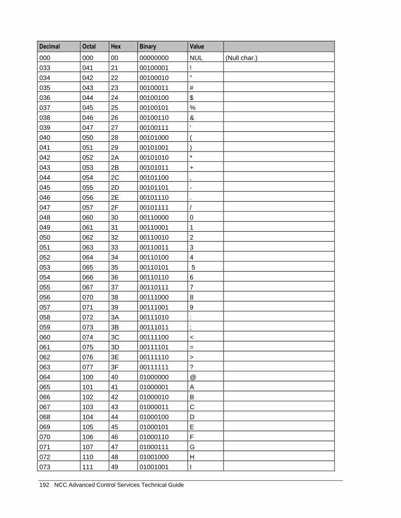
192 NCC Advanced Control Services Technical Guide
Decimal Octal Hex Binary Value
000 000 00 00000000 NUL (Null char.)
033 041 21 00100001 !
034 042 22 00100010 "
035 043 23 00100011 #
036 044 24 00100100 $
037 045 25 00100101 %
038 046 26 00100110 &
039 047 27 00100111 '
040 050 28 00101000 (
041 051 29 00101001 )
042 052 2A 00101010 *
043 053 2B 00101011 +
044 054 2C 00101100 ,
045 055 2D 00101101 -
046 056 2E 00101110 .
047 057 2F 00101111 /
048 060 30 00110000 0
049 061 31 00110001 1
050 062 32 00110010 2
051 063 33 00110011 3
052 064 34 00110100 4
053 065 35 00110101 5
054 066 36 00110110 6
055 067 37 00110111 7
056 070 38 00111000 8
057 071 39 00111001 9
058 072 3A 00111010 :
059 073 3B 00111011 ;
060 074 3C 00111100 <
061 075 3D 00111101 =
062 076 3E 00111110 >
063 077 3F 00111111 ?
064 100 40 01000000 @
065 101 41 01000001 A
066 102 42 01000010 B
067 103 43 01000011 C
068 104 44 01000100 D
069 105 45 01000101 E
070 106 46 01000110 F
071 107 47 01000111 G
072 110 48 01001000 H
073 111 49 01001001 I
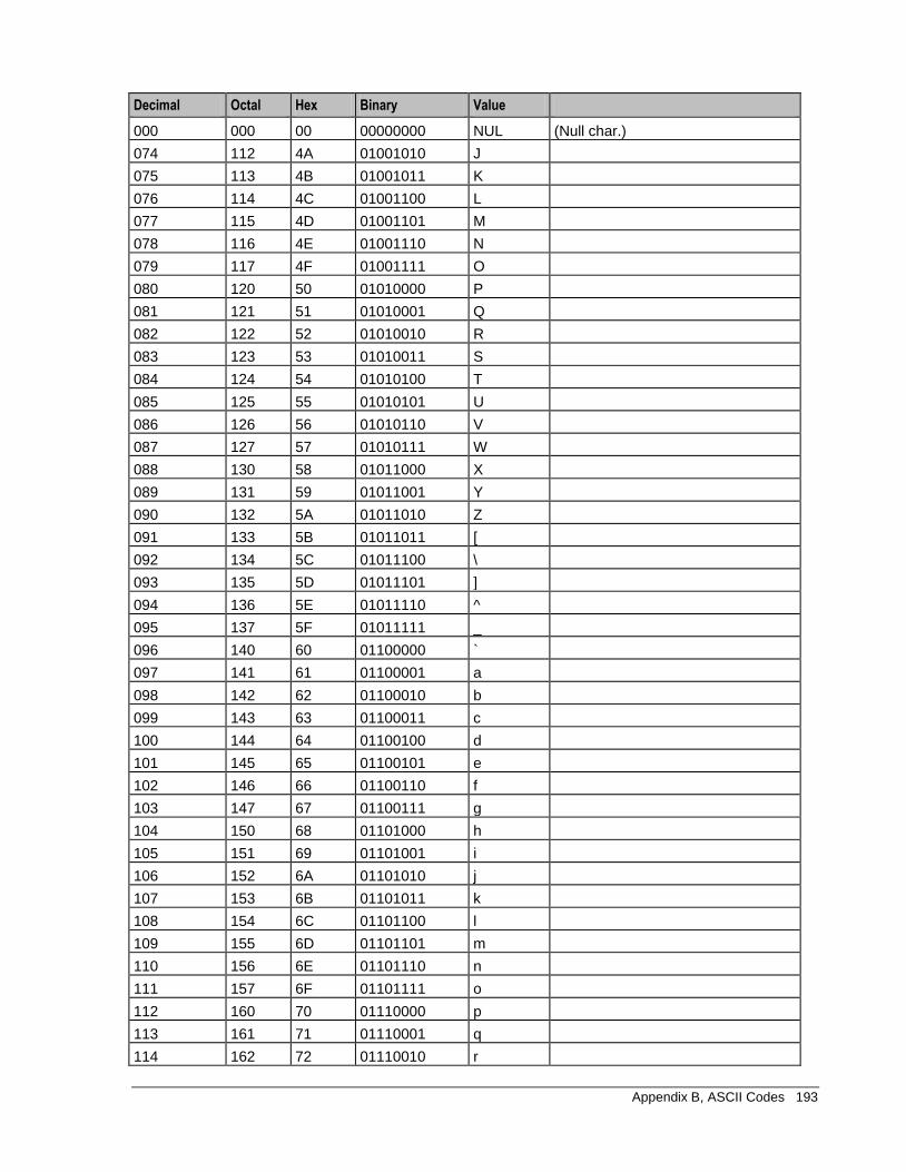
Appendix B, ASCII Codes 193
Decimal Octal Hex Binary Value
000 000 00 00000000 NUL (Null char.)
074 112 4A 01001010 J
075 113 4B 01001011 K
076 114 4C 01001100 L
077 115 4D 01001101 M
078 116 4E 01001110 N
079 117 4F 01001111 O
080 120 50 01010000 P
081 121 51 01010001 Q
082 122 52 01010010 R
083 123 53 01010011 S
084 124 54 01010100 T
085 125 55 01010101 U
086 126 56 01010110 V
087 127 57 01010111 W
088 130 58 01011000 X
089 131 59 01011001 Y
090 132 5A 01011010 Z
091 133 5B 01011011 [
092 134 5C 01011100 \
093 135 5D 01011101 ]
094 136 5E 01011110 ^
095 137 5F 01011111 _
096 140 60 01100000 `
097 141 61 01100001 a
098 142 62 01100010 b
099 143 63 01100011 c
100 144 64 01100100 d
101 145 65 01100101 e
102 146 66 01100110 f
103 147 67 01100111 g
104 150 68 01101000 h
105 151 69 01101001 i
106 152 6A 01101010 j
107 153 6B 01101011 k
108 154 6C 01101100 l
109 155 6D 01101101 m
110 156 6E 01101110 n
111 157 6F 01101111 o
112 160 70 01110000 p
113 161 71 01110001 q
114 162 72 01110010 r
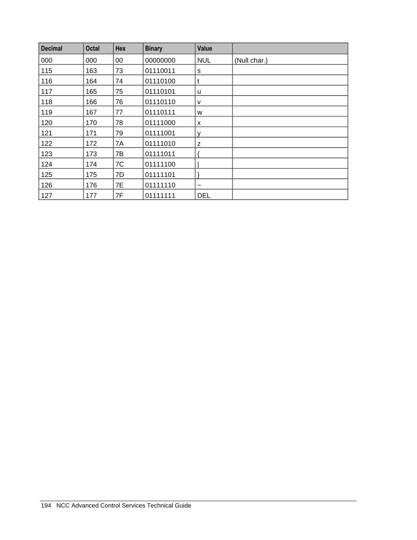
194 NCC Advanced Control Services Technical Guide
Decimal Octal Hex Binary Value
000 000 00 00000000 NUL (Null char.)
115 163 73 01110011 s
116 164 74 01110100 t
117 165 75 01110101 u
118 166 76 01110110 v
119 167 77 01110111 w
120 170 78 01111000 x
121 171 79 01111001 y
122 172 7A 01111010 z
123 173 7B 01111011 {
124 174 7C 01111100 |
125 175 7D 01111101 }
126 176 7E 01111110 ~
127 177 7F 01111111 DEL
Glossary 195
NCC Glossary of Terms
AAA
Authentication, Authorization, and Accounting. Specified in Diameter RFC 3588.
ACS
Advanced Control Services configuration platform.
ANI
Automatic Number Identification - Term used in the USA by long-distance carriers for CLI.
ASN.1
Abstract Syntax Notation One - a formal notation used for describing data transmitted by telecommunications protocols. ASN.1 is a joint ISO/IEC and ITU-T standard.
BCSM
Basic Call State Model - describes the basic processing steps that must be performed by a switch in order to establish and tear down a call.
C7
See SS7.
CAMEL
Customized Applications for Mobile network Enhanced Logic
This is a 3GPP (Third Generation Partnership Project) initiative to extend traditional IN services found in fixed networks into mobile networks. The architecture is similar to that of traditional IN, in that the control functions and switching functions are remote. Unlike the fixed IN environment, in mobile networks the subscriber may roam into another PLMN (Public Land Mobile Network), consequently the controlling function must interact with a switching function in a foreign network. CAMEL specifies the agreed information flows that may be passed between these networks.
CAP
CAMEL Application Part
CC
Country Code. Prefix identifying the country for a numeric international address.
CCR
Credit-Control-Request, used in Diameter by the credit-control client to request credit authorization from the credit-control server.
CCS
1) Charging Control Services (or Prepaid Charging) component.
196 NCC Advanced Control Services Technical Guide
2) Common Channel Signalling. A signalling system used in telephone networks that separates signalling information from user data.
CDR
Call Data Record
Note: The industry standard for CDR is EDR (Event Detail Record). Over time EDR will replace CDR in the Oracle documentation.
CID
Call Instance Data
CLI
Calling Line Identification - the telephone number of the caller. Also referred to as ANI.
Connection
Transport level link between two peers, providing for multiple sessions.
CPE
Control Plan Editor (previously Call Plan Editor) - software used to define the logic and data associated with a call -for example, "if the subscriber calls 0800 nnnnnn from a phone at location xxx then put the call through to bb bbb bbbb".
CPU
Central Processing Unit
cron
Unix utility for scheduling tasks.
crontab
File used by cron.
CS1
ETSI INAP Capability Set 1. An ITU standard.
CSV
A Comma-Separated Values file contains the values in a table as a series of ASCII text lines organized so that each column value is separated by a comma from the next column's value and each row starts a new line, for example:
Doe,John,944-7077
Johnson,Mary,370-3920
Smith,Abigail,299-3958
(etc.)
A CSV file is a way to collect the data from any table so that it can be conveyed as input to another table-oriented application such as a relational database application. Microsoft Excel can read CSV files. A CSV file is sometimes referred to as a flat file.
Glossary 197
DB
Database
Diameter
A feature rich AAA protocol. Utilises SCTP and TCP transports.
DLE
Destination Local Exchange
DP
Detection Point
DRA
Destination Routing Address. The parameter in the INAP Connect operation, sent from ACS to the SSP. This is the number the SSP is instructed to connect to.
DTMF
Dual Tone Multi-Frequency - system used by touch tone telephones where one high and one low frequency, or tone, is assigned to each touch tone button on the phone.
EDR
Event Detail Record
Note: Previously CDR. The industry standard for CDR is EDR (Event Detail Record). Over time EDR will replace CDR in the NCC documentation.
ETSI
European Telecommunications Standards Institute
FCI
Furnish Charging Information. An INAP operation sent from ACS to the SSP to control the contents of EDRs produced by the SSP.
FDA
First Delivery Attempt - the delivery of a short message directly to the SME rather than relaying it through the MC.
GMLC
The Gateway Mobile Location Centre contains functionality required to support LCS (LoCation Services).
GPRS
General Packet Radio Service - employed to connect mobile cellular users to PDN (Public Data Network- for example the Internet).

198 NCC Advanced Control Services Technical Guide
GSM
Global System for Mobile communication.
It is a second generation cellular telecommunication system. Unlike first generation systems, GSM is digital and thus introduced greater enhancements such as security, capacity, quality and the ability to support integrated services.
GT
Global Title.
The GT may be defined in any of the following formats:
Type 1: String in the form "1,<noa>,<BCD address digits>"
Type 2: String in the form "2,<trans type><BCD address digits>"
Type 3: String in the form "3,<trans type>,<num plan>,<BCD address digits>"
Type 4: String in the form "4,<trans type>,<num plan>,<noa>,<BCD address digits>"
The contents of the Global Title are defined in the Q713 specification, please refer to section 3.4.2.3 for further details on defining Global Title.
GUI
Graphical User Interface
GVNS
Global Virtual Numbering Scheme - When multiple VPNs are in use by a customer, the capability to route calls between these VPNs requires a numbering scheme that uses destination addresses based on a customer id and extension number. These GVNS addresses can then be interpreted to provide inter VPN operation.
HLR
The Home Location Register is a database within the HPLMN (Home Public Land Mobile Network). It provides routing information for MT calls and SMS. It is also responsible for the maintenance of user subscription information. This is distributed to the relevant VLR, or SGSN (Serving GPRS Support Node) through the attach process and mobility management procedures such as Location Area and Routing Area updates.
HPLMN
Home PLMN
HTML
HyperText Markup Language, a small application of SGML used on the World Wide Web.
It defines a very simple class of report-style documents, with section headings, paragraphs, lists, tables, and illustrations, with a few informational and presentational items, and some hypertext and multimedia.
Hunting
A terminating call feature where a subscriber may request a list of alternate destination addresses. If their mobile station is not attached, or does not answer a call, then the service logic should attempt to reach the supplied alternate destinations in sequence.
Glossary 199
ICA
InitiateCallAttempt. A CAMEL/INAP operation sent by the SLC to an SSP request that a voice call is started.
IDP
INAP message: Initial DP (Initial Detection Point)
IMSI
International Mobile Subscriber Identifier. A unique identifier allocated to each mobile subscriber in a GSM and UMTS network. It consists of a MCC (Mobile Country Code), a MNC (Mobile Network Code) and a MSIN (Mobile Station Identification Number).
The IMSI is returned by the HLR query (SRI-SM) when doing FDA. This tells the MSC exactly who the subscriber is that the message is to be sent to.
IN
Intelligent Network
INAP
Intelligent Network Application Part - a protocol offering real time communication between IN elements.
Initial DP
Initial Detection Point - INAP Operation. This is the operation that is sent when the switch reaches a trigger detection point.
IP
1) Internet Protocol
2) Intelligent Peripheral - This is a node in an Intelligent Network containing a Specialized Resource Function (SRF).
IP address
Internet Protocol Address - network address of a card on a computer
ISDN
Integrated Services Digital Network - set of protocols for connecting ISDN stations.
ISUP
ISDN User Part - part of the SS7 protocol layer and used in the setting up, management, and release of trunks that carry voice and data between calling and called parties.
ITU
International Telecommunication Union
200 NCC Advanced Control Services Technical Guide
IVR
Interactive Voice Response - systems that provide information in the form of recorded messages over telephone lines in response to user input in the form of spoken words or, more commonly, DTMF signalling.
LAC
Location Area Code. This is an integer value specified as the third level of detail in the location area information. One LAC contains multiple Cell IDs or SAIs.
MAP
Mobile Application Part - a protocol which enables real time communication between nodes in a mobile cellular network. A typical usage of the protocol would be for the transfer of location information from the VLR to the HLR.
MC
Message Centre. Also known as SMSC.
MCC
Mobile Country Code. In the location information context, this is padded to three digits with leading zeros. Refer to ITU E.212 ("Land Mobile Numbering Plan") documentation for a list of codes.
Messaging Manager
The Messaging Manager service and the Short Message Service components of Oracle Communications Network Charging and Control product. Component acronym is MM (formerly MMX).
MM
Messaging Manager. Formerly MMX, see also XMS (on page 204) and Messaging Manager (on page 200).
MNC
Mobile Network Code. The part of an international address following the mobile country code (MCC), or at the start of a national format address. This specifies the mobile network code, that is, the operator owning the address. In the location information context, this is padded to two digits with a leading zero. Refer to ITU E.212 ("Land Mobile Numbering Plan") documentation for a list of codes.
MO
Mobile Originated
MS
Mobile Station
MSC
Mobile Switching Centre. Also known as a switch.

Glossary 201
MSIN
Mobile Station Identification Number.
MSRN
Mobile Station Roaming Number
MT
Mobile Terminated
MTP
Message Transfer Part (part of the SS7 protocol stack).
NOA
Nature Of Address - a classification to determine in what realm (Local, National or International) a given phone number resides, for the purposes of routing and billing.
NP
Number Portability
NPI
Number Plan Indicator
Octet
Byte - 8 bits.
Oracle
Oracle Corporation
PACUI
Play Announcement and Collect User Information
PC
Point Code. The Point Code is the address of a switching point.
PIN
Personal Identification Number
PLMN
Public Land Mobile Network
RIMS
Routing Information for Mobile Services. Used to cache HLR lookup information.
Note: Now known as "Messaging Manager Navigator".
202 NCC Advanced Control Services Technical Guide
SCCP
Signalling Connection Control Part (part of the SS7 protocol stack).
SCCP Address
Is made up of PC + SSN + GT; or PC +SSN; or GT; or GT + PC.
SCF
Service Control Function - this is the application of service logic to control functional entities in providing Intelligent Network services.
SCI
Send Charging Information. An INAP operation sent from ACS to the SSP to control real time charging by the SSP.
SCP
Service Control Point. Also known as SLC.
SCTP
Stream Control Transmission Protocol. A transport-layer protocol analogous to the TCP or User Datagram Protocol (UDP). SCTP provides some similar services as TCP (reliable, in-sequence transport of messages with congestion control) but adds high availability.
Session
Diameter exchange relating to a particular user or subscriber access to a provided service (for example, a telephone call).
SGML
Standard Generalized Markup Language. The international standard for defining descriptions of the structure of different types of electronic document.
SGSN
Serving GPRS Support Node
SK
Service Key
SLC
Service Logic Controller (formerly UAS).
SLEE
Service Logic Execution Environment
Glossary 203
SME
Short Message Entity - an entity which may send or receive Short Messages. It may be located in a fixed network, a mobile, or an SMSC.
SMS
Depending on context, can be:
Short Message Service
Service Management System platform
NCC Service Management System application
SN
Service Number
SQL
Structured Query Language - a database query language.
SRF
Specialized Resource Function - This is a node on an IN which can connect to both the SSP and the SLC and delivers additional special resources into the call, mostly related to voice data, for example play voice announcements or collect DTMF tones from the user. Can be present on an SSP or an Intelligent Peripheral (IP).
SRI
Send Routing Information - This process is used on a GSM network to interrogate the HLR for subscriber routing information.
SS7
A Common Channel Signalling system used in many modern telecoms networks that provides a suite of protocols which enables circuit and non circuit related information to be routed about and between networks. The main protocols include MTP, SCCP and ISUP.
SSF
Sub Service Field.
SSN
Subsystem Number. An integer identifying applications on the SCCP layer.
For values, refer to 3GPP TS 23.003.
SSP
Service Switching Point
Switching Point
Anything that can send and receive C7 messages.
204 NCC Advanced Control Services Technical Guide
System Administrator
The person(s) responsible for the overall set-up and maintenance of the IN.
TCAP
Transaction Capabilities Application Part – layer in protocol stack, message protocol.
TCP
Transmission Control Protocol. This is a reliable octet streaming protocol used by the majority of applications on the Internet. It provides a connection-oriented, full-duplex, point to point service between hosts.
Telco
Telecommunications Provider. This is the company that provides the telephone service to customers.
Telecommunications Provider
See Telco.
Termination Number
The final number that a call terminates to. Can be set in control plan nodes such as Attempt Termination and Unconditional Termination for re-routing numbers such as Toll Free or Follow Me numbers.
VLR
Visitor Location Register - contains all subscriber data required for call handling and mobility management for mobile subscribers currently located in the area controlled by the VLR.
VPN
The Virtual Private Network product is an enhanced services capability enabling private network facilities across a public telephony network.
VWS
Oracle Voucher and Wallet Server (formerly UBE).
WSDL
Web Services Description Language.
XMS
Three letter code used to designate some components and path locations used by the Oracle Communications Network Charging and Control Messaging Manager (on page 200) service and the Short Message Service. The published code is MM (on page 200) (formerly MMX).
Index 205
Index
A
AAA • 199 About applet parameters in .html files • 24 About customizing the ACS UI • 23 About defining scfs in acs.jnlp and sms.jnlp •
120 About defining ssfs in acs.jnlp and sms.jnlp •
126 About Global Control Plans • 184 About Installation and Removal • 175 About This Document • vii Accessing ACS • 23 Accessing ACS directly • 10 Accessing ACS through SMS • 9 ACS • 199 ACS CDR/EDR • 7 ACS Client Specifications • 171 ACS Configuration in the eserv.config File • 36 ACS Global Control Plans • 184 ACS packages • 175 ACS primary tags • 5 ACS section • 36 ACS User Privilege Levels • 11 acs.conf • 57 acs.conf Example • 141 ACS_ROOT • 20 acsAddCallPlan • 159, 164 acsAddCustomer • 160 acsAddGeography • 162 acsAddServiceNumber • 162 acsChassis • 59 acsChassis AWOL Configuration • 136 acsChassis EDR Configuration (SLC) • 126 acsChassis Emergency Numbers (SLC) • 95 acsChassis INAP Extension Parameters • 95,
110 acsChassis Normalization Parameters (SLC) •
98 acsChassis plugin libraries • 60 acsChassis Plug-ins • 59 acsChassis SCF Configuration (SLC) • 117 acsChassis Service Library Configuration (SLC)
• 135 acsChassis Service Normalisation Parameters
(SLC) • 136 acsChassis ServiceEntry Configuration (SLC) •
45, 48, 59, 105, 136, 138, 158 acsChassis Single Instance Parameters (SLC) •
68 acsChassis SLEE Event Size Parameter (SLC)
• 104, 113 acsChassis SRF Configuration (SLC) • 62, 113 acsChassis SSF Configuration (SLC) • 29, 31,
120
acsChassisActions Configuration • 40 acsCompilerDaemon • 150 acsCompilerDaemon (SMS) • 64 acsDbCleanup.sh • 153 acsDecompile • 163 acsDumpControlPlan • 159, 164 acsMonitorCompiler • 165 acsProfileCompiler • 154 acsScheduleCallPlan • 165 acsSetupAnnouncement • 166 acsSnCpActAlarms • 151 acsStatisticsDBInserter • 154 acsStatisticsDBInserter (SMS) • 62 acsStatsLocal (SLC) • 94 acsStatsMaster • 156 acsStatsMaster (SLC) • 67 acsTriggerIF Configuration • 48 addChargingInfoToCTR • 69 addChargingInfoToETC • 69 addChargingInfoToPA • 69 AddMOLIPrefix • 70 Address • 114, 117, 121 AddressSources • 45 alarmCheckInterval • 152 alarmReason • 153 alertTimeout • 65 allowCallPlanSchedulingInPast • 24 allowRefInCustCombo • 24 alternativeCallPlanNamePostfix • 70 alwaysIncludePartyToCharge • 70 ANI • 199 appContext • 119, 125 armDisconnectAt • 71 armDisconnectAtp • 71 armDisconnectLeg1 • 71 armDisconnectLeg2 • 71 armLegsSeparately • 71 ArmTerminateTriggers • 71 ASCII Codes • 195 AskCirAttemptElapsedTime • 91 AskCirCallAddress • 91 AskCirConnectElapsedTime • 91 AskCirReleaseCause • 91 AskCirStopTime • 91 ASN.1 • 199 AssumePreArrangedEnd • 72 atDisconnectMM_Leg1Interrupt • 72 atDisconnectMM_Leg2Interrupt • 72 Audience • vii AuditChallenge • 67, 72 autoCloseCompilerDialog • 25 autoCloseCPE • 25 Automated ACS Processes (SLC Machine) •
156 Automated ACS Processes (SMS Machine) •
149 AWOL processing • 136
206 NCC Advanced Control Services Technical Guide
awolOverrideACRTimeout • 139 awolReportOnly • 112, 138 awolReportPeriod • 112, 139 awolTimeout • 112, 137
B
Background Processes • 149 BCSM • 199 Before you begin • 58
C
C7 • 199 Call Dump parameters • 90 Call Information Report parameters • 90 Call processing and features • 1 Call routing services • 2 callAnswerTimeFormat • 41 CallDumpDir • 90 CallDumpEnabled • 90 CallDumpMessage • 90 CallDumpSeconds • 90 CallDumpSeverity • 90 CalledPartyBcdToNoaMap • 73 callEndTimeFormat • 41 CallInitiationExtensionForIdp • 72 CallInitiationTimeoutToleranceSeconds • 72 CallInitiationUseContextInd • 73 callProcessingAllowedAfterAPartyDisconnect •
74 callReferenceIDAsHex • 127 callStartTimeFormat • 42 CallType • 106 CAMEL • 199 CancelChar • 74 CAP • 199 CarrierCodeDisposal • 74 CC • 199 CCR • 199 CCS • 199 CDR • 200 CdrClosedDirectory • 127 CdrCompressCall • 127, 134 CdrCurrentDirectory • 128 CdrExtraFields • 128 CdrFile • 128 CdrFileAppendCloseTime • 129 CdrFileAppendPid • 130 CdrFileMaxAge • 126, 127, 130 CdrFileMaxSize • 126, 127, 130 CdrFileUseGMT - 10291824 • 130 CdrFileUseLocalTime - 10291824 • 131 CdrLogPIN • 133 CdrOnAbort • 127, 133 CdrOnDisconnect • 127, 133 cdrOnForcedDisc • 134 CdrOnHandover • 134 CdrRemoveFields • 131
CdrResetOnWriteRELC • 134 ChainCountLimit • 75 ChassisPlugin • 60, 61, 157 checkAWOL • 137 checkAWOLMarginAC • 137 Checking Kernel parameters • 172 Checking the Installation • 177 Checklist - SLC • 179 Checklist - SMS • 178 CheckMOLIPrefix • 70, 75 CID • 200 CLI • 200 CollectInfoReturnsAll • 75 compressAtKb • 66 compressLevel • 66 Configuration • 157, 158, 159, 160, 162, 164,
165, 166 Configuration - acsDecompile • 163 Configuration file format • 35 Configuration files • 20 Configuring minimumSizeOfConnectSleeEvent
per service • 105, 113 Configuring the acs.conf • 20, 57, 150, 154,
156, 157, 158 Configuring the Environment • 19 Configuring the eserv.config • 35 Configuring the numberDataImport Tool • 167,
169 ConnectCLISource • 108 Connection • 200 Context Tag • 97 Copyright • ii CopySpareBits • 75 countryCodes • 37 CPE • 200 CPU • 200 Creating and Updating Table Lookup Datasets •
167, 168 Creating the Dataset Input File • 167, 168 cron • 200 crontab • 200 CS1 • 200 CSV • 200
D
DB • 201 Default.lang • 21 Default_Acs_Service.hs • 22 defaultTelcoManaged • 26 Defining acsChassis AWOL configuration • 136 Defining the Help Screen Language • 22 Defining the Screen Language • 20 Defining the Security Levels • 10 deleteTagsAfterTrigger • 49 DenormalisationRule • 99, 101, 104, 140 Description • 1, 187, 195 destAddress • 38
Index 207
dfcOnIpAbort • 76 Diagram • 3, 126 DialledHashEncoding • 76 DialledStarEncoding • 76 dialogTickInterval • 76 Diameter • 201 DigitsInAnnouncementList • 69 disarmEDPs • 76 DisconnectMidCallJumpBack • 76 DLE • 201 Document Conventions • viii DP • 201 DRA • 201 DTMF • 201
E
Editing the file • 36 edpArmAbandoned • 77 edpArmAnswer • 77 edpArmBusy • 77 edpArmNoAnswer • 77 edpArmRouteSelectFailure • 77 edpSetNoAnswerTimer • 77 edpUseNoAnswerTimer • 78 EDR • 201 elapsedTimesFromApplyChargingReport • 134 EmergencyNumber • 95 emptyDraIsError • 78 enabled • 38 encoding • 40 endUnlinkedExits • 66 EntryChar • 78 eserv.config Configuration • 20, 35 eserv.config files delivered • 36 eserv.config parameters • 151 ETC_CorrelationIdInIPAddr • 78 ETC_MinCorrelationDigits • 78 ETC_SCF_ID • 79 ETSI • 201 Example • 112, 113, 117, 118, 119, 120, 125 Example 1 • 58, 104 Example 2 • 58, 104 Example 3 • 104 Example ACS Configuration in eserv.config •
36, 52 Example acs.conf • 141 Example acs_devices.sh file • 177 Example configuration sections • 58 Example helpset language • 22 Example jnlp applet parameters • 33 Example MRC configuration in eserv.config • 56 Example screen language • 21 Extension numbers example • 72, 98 Extra statistics • 79, 93 extractCallAnswerTime • 42 extractCallEndTime • 42 extractCallStartTime • 42
extractEdrId • 43 extractEdrTimeZone • 43 Extraction sources in IDP • 107, 108, 109 Extraction value construction • 110 extraStats • 79, 93
F
Failure • 150, 153, 154, 155, 156 fakeAcrCallReleaseAtMaxDuration • 79 FakeAcrCallReleaseAtTcpExpiry • 79 fakeMissingAcrAtDisconnection • 80 FCI • 201 fciInSeparateMessage • 80 fciInSeparateMessageAllOperations • 80 fciMaximumLength • 81 fciSeparator • 81 FDA • 201 FirstDigitTimeout • 81
G
G digits • 111 Get Hunting Number Node Configuration • 139,
157 Global and service specific normalization • 99 GlobalProfileMaxAge • 81 GMLC • 201 GPRS • 201 GSM • 202 GT • 202 GUI • 202 GVNS • 202
H
HLR • 202 How the SRF configuration works • 115 HPLMN • 202 HTML • 202 Hunting • 202
I
ICA • 203 Icons • 175 ID • 96 IDP • 203 IDPExtTypeCallAnswerTime • 43 IDPExtTypeCallEndTime • 43 IDPExtTypeCallStartTime • 44 IDPExtTypeEDRId • 44 IDPExtTypeEDRTimeZone • 44 ignoreNumberPlanForConnectToContinue • 81 Implementing parameter changes • 58 IMSI • 203 IN • 203 INAP • 203 inapServiceKey • 49 Initial DP • 203
208 NCC Advanced Control Services Technical Guide
inNOA • 101 inPrefix • 101 Installation and Removal Overview • 175 Installing acsSms Packages on a Clustered
SMS • 176 InterDigitTimeout • 81 interface • 125 InternalErrorAction • 82 Introduction • 7, 9, 10, 12, 16, 20, 22, 35, 57,
62, 64, 67, 94, 95, 104, 105, 113, 117, 120, 136, 149, 156, 172, 175, 177, 180, 183, 187
IP • 203 IP address • 203 IPProtocolInfo • 82 ISDN • 203 issuePCClockWarning • 26 ISUP • 203 ITU • 203 IVR • 204
J
Java applet parameters • 24
L
LAC • 204 libacsChassisActions • 61, 157 libacsMacroNodes • 61, 157 libacsService • 158 libname • 109 Location • 150, 151, 153, 154, 155, 156, 160,
162, 163, 165, 166 LocationInfoDestinationSubsystemNumber • 54 LocationInfoGSMScfAddress • 54 LocationInfoGSMScfMapNoa • 55 locationInfoOriginatingSubsystemNumber • 55 locationInfoPollEnabled • 55 LocationInfoRequestTimeout • 55 locationInfoRetrieval configuration • 54 locationInfoTcapInterfaceName • 56 Logging EDRs • 126 LogicalCPSource • 107 logo • 26
M
MacroNodePluginFile • 59, 61, 157 macroNodes Configuration • 37 MAP • 204 MasterServerLocation • 64 MasterServerPort • 63 masterStatsServer • 68, 94 MAX_CONTROL_PLANS_DISPLAYED • 27 maxAnnouncementTextBytes • 82 maxBranches • 65 maxCompiledKb • 66 maximiseAcsScreens • 27 maxLength • 103 maxNodes • 65
MaxPromptDigits • 82 MC • 204 MCC • 204 Memory • 171 Messaging Manager • 204, 208 Methods • 46 minimumSizeOfConnectSleeEvent • 105 minLength • 102 MinZeroTimeRemainingPeriod • 82 MM • 204, 208 MNC • 204 MO • 204 MRC Configuration • 54 MS • 204 MSC • 204 mscAddress • 40 mscAddressForEdr • 40 msgmnb • 173 msgtql • 172 MSIN • 205 MSRN • 205 MT • 205 MTP • 205
N
Network • 171 NetworkCPSource • 107 NI • 119 NOA • 114, 118, 121, 205 NOA and normal rules • 98 noActivitySleepTime • 50 NOA-ISUP type • 112 NOA-MAP type • 111 NoAnswerTimeout • 82 NOAToAdd • 101 NoCallPlanAction • 82 NoCallPlanCause • 83 NoCallPlanError • 83 NoDatabaseConnectAction • 83 Node states • 128, 129 NokiaCIR • 91 noOfDigitsToRemove • 102 NormalisationRule • 100 normaliseServiceNumber • 103 normaliseTerminationNumber • 103 Normalization parameters • 99, 136 NormalUnknownNOA • 100 NormalUseHex • 100 NoServiceAction • 83 NoServiceError • 83 Note • 183 NP • 205 NPI • 118, 122, 205 Number • 95 Number denormalization • 99 Number Matching Node Configuration • 140 Number normalization • 99

Index 209
numberDataImport • 167 numberRules • 50 NumberRulesSection • 140
O
Octet • 205 Oracle • 205 Oracle usr/pwd string • 20, 62 Oracle variables • 20 oraclepassword • 63, 64, 67 oracleUserIdPassword • 151 oracleusername • 62, 64, 67 origAddress • 38 OriginalCalledPartyID • 109 Originating announcements • 183 Other features • 1 outNOA • 102 outPrefix • 102 Output • 151, 153, 154, 155, 156, 157 OverrideDefaultIPDigitTimeout • 83 overrideSleeServiceKey • 50 Overriding AWOL configuration per service •
112, 137 Overview • 1, 9, 19, 35, 57, 149, 159, 171, 175,
183 overwriteFci • 84
P
PACUI • 205 paletteStyle • 27 Parameter • 113, 117, 135 Parameter types • 58 Parameters • 62, 64, 67, 68, 94, 95, 106, 120,
122, 127, 137, 139, 140, 150, 151, 153, 154, 155, 156, 172
PC • 118, 123, 205 PendingTNSource • 108 Period • 63 Permission Levels • 11 PersistantAuthorisationInfo • 84 PIN • 205 PIN logging parameters • 89, 133 PINLogEnable • 89 PINLogFail • 89 PINLogMaxAge • 89 PINLogMaxSize • 89 PINLogSuccess • 90 Play Number Announcement node
denormalization rules • 103 Play Variable Part Announcement Node
Configuration • 140, 157 PLMN • 205 Plug-in list • 61 Plugins • 150 port • 68, 69, 94 postAnswerBeepTimer • 84 Post-Installation Procedures • 183
Pre-installation • 171 Preparing the System • 172 Prerequisites • vii Procedure • 12, 16, 21, 22, 59 Process list - SCP • 180 Process list - SMP • 179, 180 Profile • 28 ProfileOrder • 135 Purpose • 150, 151, 153, 154, 155, 156, 157,
158, 159, 160, 162, 163, 164, 165, 166, 167
R
Raw devices • 176 Raw devices configuration • 176 recordSmpStatistics • 84, 92 RedirectingPartyID • 109 RegMapFlushPeriod • 140 RegMapMaxAge • 141 Related documents • vii ReleaseInApplyCharging • 37 repeatAlarm • 152 requireCustomerReference • 29 Response times • 172 Retries • 63 RI • 119, 125 RIMS • 205 roundDownACRCallDuration • 85 rrbcsmePrefix • 84
S
SCCP • 206 SCCP Address • 206 SCF • 206 scfName • 117 scfs • 29 SCI • 206 sciMaximumLength • 84 Scope • vii SCP • 206 Screen • 172 screening • 48 SCTP • 206 Security in ACS • 9 Security Overview • 9 semKey • 68, 69 semmni • 173 semmns • 173 semmsl • 173 semopm • 174 semvmx • 174 SendCIR • 91 sendFciWithReleaseCall • 85 sendIdenticalCliInConnect • 85 Sequence • 96 Service specific normalization parameters • 136 ServiceEntries Configuration • 45 ServiceEntry • 59
210 NCC Advanced Control Services Technical Guide
ServiceName • 47, 106 serviceNumberTerm • 152 Session • 206 SessionTimeInformation configuration • 41 setCallData • 139 Setting the ACS root directory • 19 Setting up ACS Security through SMS • 12 Setting up ACS Security without using SMS •
16 Setting up the Screens • 23, 120, 126 SGML • 206 SGSN • 206 shmKey • 68, 69 shmmax • 173 shmmin • 173 shmmni • 173 shmseg • 173 showAnnouncementSource • 30 showCallPlanCopy • 30 showNetwork • 30 SK • 206 SLC • 206 SLC packages • 181 SLEE • 206 sleeInterfaceName • 50 sleeServiceKey • 51 SME • 207 SMS • 207 SMS packages • 180 smsLogCleaner • 155 smsStatsPeriodCheck • 85 SN • 207 source • 48 sourceSelectionOnHandover • 86 Specifications • 171 SQL • 207 srf • 60, 62 SRF • 207 srfName • 114 SRI • 207 SS7 • 207 SSF • 207 ssf_name • 121 ssfs • 31 SSN • 119, 123, 207 SSP • 207 Standard profile block list • 3 Startup • 150, 151, 153, 154, 155, 156, 157,
158 Statistics captured • 84, 92 Statistics Updated by acsTriggerIF • 51 statisticsEnabled • 51 statsReportingLevel • 86 STIServiceKey • 44 Subfield • 96 suppressedSDRDigits • 31 SuppressTagID • 31
Switching Point • 207 Syntax • 105 syslogLevel • 86 System Administrator • 208 System Manifest • 180 System Overview • 1
T
TcAbortOnPreArrangedEnd • 87 TCAP • 208 tcapPreEnd • 115 TCP • 208 TCP Network Loading • 126 Telco • 208 Telecommunications Provider • 208 Termination Number • 208 Time Zones • 32, 187 Tools and Utilities • 159 traceDebugLevel • 39 Tracing Configuration • 38 triggerTimeOutSecs • 51 TrimFStop • 87 TT • 118, 122 Type • 96 TypeOfSrf • 115 Typographical Conventions • viii TZ • 32 tzDefault • 87
U
updateCPReferences • 32 UseContinueOperation • 87 UseETC • 114 UseLanguageExtensions • 88 usePendingTnForCaInCdr • 91 UseReplication • 89 useTNForNodeName • 33 Using Announcements • 183
V
VLR • 208 VPN • 208 VWS • 208
W
What are the Functions of ACS? • 7 What are the Main Components of ACS? • 3 What is the Advanced Control Services? • 1 WSDL • 208
X
XMS • 204, 208
Z
zeroElapsedTimesInCdr • 135