Embed Size (px)
Citation preview

What's New
2018


What's New in GRAITEC Advance BIM Designers 2018
3
Table of Contents
WELCOME TO GRAITEC ADVANCE BIM DESIGNERS 2018 ...................................................................... 5
ADVANCE BIM DESIGNERS – CONCRETE SERIES ..................................................................................... 6
NEWS ................................................................................................................................................................... 6 Compliancy with Revit 2017 and Revit 2018 .................................................................................................. 6 Reinforcement Tools ....................................................................................................................................... 6 Design Group .................................................................................................................................................. 6 Customizable annotations and Bending details .............................................................................................. 8 Synchronization – import/export on selection (multiple elements) ............................................................... 11 Improvements to calculation speed using multi process approach .............................................................. 13 Non-linear second order calculation method ................................................................................................ 14 External loads along the column height ........................................................................................................ 15 Spring supports for columns ......................................................................................................................... 16 Multi-layer soil profile .................................................................................................................................... 17
IMPROVEMENTS .................................................................................................................................................. 18 Automatically updated Revit schedules ........................................................................................................ 18 Synthetic Reports .......................................................................................................................................... 19 Preview Schedule ......................................................................................................................................... 20 Improved GRAITEC custom families ............................................................................................................ 21 Family-based openings in beams ................................................................................................................. 21 User-defined result sections along beam ..................................................................................................... 22 Longitudinal bars on supports ....................................................................................................................... 23 Linear loads over supports ............................................................................................................................ 24 Interactive section on beams ........................................................................................................................ 25 Context menus .............................................................................................................................................. 26 Display settings for load cases and dimensions ........................................................................................... 26 Drawing improvements for Advance BIM Designers Standalone and in Revit ............................................. 27
ADVANCE BIM DESIGNERS – STEEL SERIES .......................................................................................... 28
STEEL CONNECTION DESIGNER 2018 .................................................................................................................. 28 Clip Angle ...................................................................................................................................................... 28 Gusset ........................................................................................................................................................... 29 Check Collisions............................................................................................................................................ 30 Predefined Templates ................................................................................................................................... 31
STAIR & RAILING DESIGNER 2018 ....................................................................................................................... 32 News ............................................................................................................................................................. 32 Improvements ............................................................................................................................................... 38


What's New in GRAITEC Advance BIM Designers 2018
5
Welcome to GRAITEC Advance BIM Designers 2018 The GRAITEC Advance BIM Designers Suite is a collection of advanced apps for automating structural design-to-detail BIM workflows and produce the technical documentation. This version 2018 is a real milestone, bringing new features and more rebar functionalities, offering new innovative packages and truly improving the BIM workflow for the concrete and steel industries.
In this version, the Advance BIM Designers are grouped under 2 series: Concrete Series and Steel Series.
The Concrete Series of the BIM Designers comes in 2 professional packages: Advance BIM Designers – Concrete Series – Rebar Detailing; Advance BIM Designers – Concrete Series – Rebar Design & Detailing.
For the Steel series, 2 new packages have been created: Advance BIM Designers – Steel Series – Connection; Advance BIM Designers – Steel Series – Stairs & Railings.
These package modifications take into account the feedback of our customers and adapt our proposal to better fit their needs.
The “Rebar Detailing“ package is the right and effective answer for the draftsman using REVIT to produce rebar drawings. It will allow users to quickly generate parametric 3D rebar cages, automate rebar views creation, automatically produce technical documentation (annotations, drawings, schedules) and provide effective tools to fine tune rebar and drawings.
With the “Rebar Design & Detailing package“, engineers access the next level of functionality and are able to design rebar cages according to Eurocodes and North American codes within Revit® or as a standalone application, as well as automatically design detailed reports, with all the requested references to the design code check.
What's New in GRAITEC Advance BIM Designers 2018
6
Advance BIM Designers – Concrete Series
News
Compliancy with Revit 2017 and Revit 2018 Advance BIM Designers 2018 is compliant with both Revit 2017 and 2018.
Reinforcement Tools In version 2018, the Reinforcement Tools panel in GRAITEC PowerPack for Revit has been migrated to the GRAITEC Concrete Design ribbon.
Thanks to this new organization of the reinforcement tools, users can access a complete set of functionalities, helping them produce reinforcement drawings within Revit®, at an optimized rate of productivity.
Design Group Construction engineers often deal with large project sites, where they need to calculate and reinforce hundreds of structural elements. For these situations, in order to slightly simplify the process, both from the site engineer and the material / bar schedules management point of view, elements are built with the same section properties, as part of a group.
By taking into account the state of efforts for all the group elements, a single reinforcement cage type is obtained and placed in the formwork. This makes it possible to deal with less reinforcement bar lengths and bar shapes.
In the design process, this result can be achieved using the Design Group concept in the Reinforced Concrete BIM Designers working on the Autodesk Revit or Advance Design platform.
Goals:
Easy management of columns / foundations and their reinforcement details in groups, which saves time when updating a project model.
Producing identical 3D rebar cages for all grouped elements (hence, a single drawing sheet, but with a rebar schedule that takes into account all elements in the group).
Defining the same geometry properties or material for all elements in a group, more precisely, having the possibility to assign the same parameters for a selection of elements;
Detecting the Theoretical Reinforcement Envelope for a group of elements and generating a real reinforcement cage.

What's New in GRAITEC Advance BIM Designers 2018
7
Revit environment: Elements in a model can be added to a group by applying the Design Group command in the GRAITEC Concrete Design ribbon.
To assign elements to a group, the elements must have:
an identical structural type (Structural Columns or Structural Foundations); an identical family (e.g. Rectangular columns, Footing with pocket, etc.); an identical section (same type); an identical material; an identical height (in the case of columns).
Note: Elements that are already part of certain groups cannot be added to other groups.
Group creation starts with applying a design template to all elements selected. A dialog opens for the user to indicate the template to be further applied to all the elements from the design group:
Note: Adding a template for the elements in the group right from the start will ensure a correct functioning and design of the elements.
Calculation is performed by selecting one of the elements in a group. If a single group element is selected and calculated, this action triggers the calculation process for the entire group (all the elements belonging to the group).
When generating a drawing, one drawing sheet per group is created, with one drawing instance for the entire group and the corresponding schedule. The schedule consists of the sum of all the reinforcement bars from the group.

What's New in GRAITEC Advance BIM Designers 2018
8
Groups can be managed, like any all elements, from the Design Status panel. One or all elements in a group are selected, and the Design Status dialog opens.
Customizable annotations and Bending details A new section was added to the Drawing Settings dialog: Bending Detail. It offers the possibility to customize the bending detail representation on the drawing, the measurement settings and the annotations.

What's New in GRAITEC Advance BIM Designers 2018
9
General Three bending detail representations are available for links: Standard, Unfold and Offset.
The possibility to choose the measurement method for partial lengths and to round the values was implemented for bending details.
For partial length measurement, three methods are available: Outside, Centerline and Polyline.
1. Measure bar segments between the exterior faces of the bar (“Outside” in GUI)
2. Measure bar segments between the axis of the bar (“Centerline” in GUI)

What's New in GRAITEC Advance BIM Designers 2018
10
3. Measure segments on the axis of the bar, the straight segments and the curved lengths (“Polyline” in GUI)
Note: For the UK localization, an additional option, based on the shape code, is available in the list. This option follows the prescriptions from British Standard BS 8666:200.
Three rounding methods are available:
Nearest Up Down
Rounding can be performed individually for bar segment length and total bar length, with an increment chosen by the user from a drop-down list.
The annotation can contain the following parameters: bars number, mark, diameter, length, spacing, total length, bar adherence and steel grade.

What's New in GRAITEC Advance BIM Designers 2018
11
Standalone vs. Revit environment In Revit, the annotations used in drawings are native Revit bar tags. The user can customize the bar description directly from the Revit interface, selecting one of the available families in the Structural Rebar Tags category.
The bending detail is not generated in the case of automatic sheet generation in Revit, but the Bending Detail command in GRAITEC Concrete Design > Reinforcement can be used instead.
Synchronization – import/export on selection (multiple elements) When using Advance BIM Designers in Revit, the synchronization functionality is available not only for single elements, but also for a multiple selection of elements.
The import/export actions can be performed from the Design Status dialog.

What's New in GRAITEC Advance BIM Designers 2018
12
The user can export/import all elements in Design Status List (the elements selected in the model) by clicking
on either or .
At this stage, you can make necessary changes for each exported element in the Standalone version of the module. Afterwards, you can import the latest element files and the element will be automatically updated in the Revit model:

What's New in GRAITEC Advance BIM Designers 2018
13
Element import/export can also be performed for individual elements:
Improvements to calculation speed using multi process approach When the BIM Designer modules for reinforced concrete are running in Advance Design, the design calculation of reinforced concrete elements is done in parallel sessions, resulting in considerable acceleration calculation for a greater number of simultaneously dimensioned objects.

What's New in GRAITEC Advance BIM Designers 2018
14
Non-linear second order calculation method Reinforced Concrete Column Designer 2018 comes with a new major functionality: the possibility to run a non-linear second order calculation.
The option is available in the Design Assumptions dialog and can be applied only for rectangular, square and circular column sections.
Note: The option is automatically selected if the user imposed spring supports (if “Manual stiffness” is selected as the calculation method in the Buckling Length dialog), or if external loads are defined in the Loads Definition dialog.
First, the engine performs a preliminary calculation using one of the EN 1992-1-1 methods. As a result, second order moments along with other efforts are obtained. The preliminary calculation is done considering only the top and bottom loads on the column, the external loads along the column height are ignored in a first stage.
Based on these efforts, a real reinforcement quantity is calculated.
Considering this real reinforcement quantity, which results in a greater column stiffness, the non-linear second order calculation is performed. Other values for the second order moment, smaller than the ones from the preliminary calculation (when the additional stiffness brought by the reinforcement was not involved), as well as new efforts along the column are obtained.
Using these final moments, a new real reinforcement quantity, smaller than the preliminary one, is obtained.
In a final step, the column section is verified using interaction curves.

What's New in GRAITEC Advance BIM Designers 2018
15
External loads along the column height Another major functionality added to Reinforced Concrete Column Designer 2018 is the possibility to define along the column height, at any abscissa of the column, lateral loads which are both punctual and distributed.
The Loads definition dialog contains two tabs: Internal efforts and External loads.
The user can decide to either define internal efforts directly, loads at the top and bottom of the column only, or to define external loads and to run a nonlinear second order calculation afterwards. The behavior is the following:
If the user defines only internal efforts, then the calculation is performed using one of the EC2 standard methods selected from the Design Assumptions dialog.
If the user decides to define only external loads, then non-linear second order calculation is automatically performed.
There is also the possibility to define both internal efforts and external loads. In this case, non-linear second order calculation is automatically performed and the obtained efforts are added to the manually defined internal efforts.

What's New in GRAITEC Advance BIM Designers 2018
16
Spring supports for columns Until version 2018, theoretical analysis considered idealized end restraints, whose translational and rotational stiffness were set to either zero (free end) or infinity (fixed end).
Along with the spring supports functionality, the influence that end restraints have on the buckling capacity is analyzed in an advanced mode, taking into account the fact that for real structures, the rotational and translational stiffness of the end restraints is somewhere between rigid and free.
In Advance BIM Designers – Concrete Series, the spring supports functionality can be found as the “Manual stiffness” option from the Buckling Length dialog. When “Manual stiffness” is selected, non-linear second order calculation automatically activates and the effective length of the column is no longer calculated using simplified formulas.
The user is allowed to define nodal stiffness against displacement and against rotation for both top and bottom ends of the column using the specific dialogs, Nodal Stiffness along X and Nodal Stiffness along Y.

What's New in GRAITEC Advance BIM Designers 2018
17
Multi-layer soil profile New to the Reinforced Concrete Footing Designer, the multi-layer functionality allows the user to set up as many soil layers as desired and to easily manage their properties. The functionality is organized in two dialogs, in the Soil panel:
Soil Profile: the main purpose is to keep the entire soil layer data organized and to provide an easy
and effective means of inserting, modifying and deleting soil layers. Soil components are organized in a table with editable fields, each line representing a defined soil type with different editable parameters (or checkboxes) available in each column.
Besides the soil grid, which is used to impose soil characteristics, the dialog contains a drawing to illustrate the succession of soil layers, in the Stratigraphy preview section. The sketch contains a plot of each previously defined soil layer with its corresponding color and displays additional info such as the level and of each layer inserted in the grid.
Soil Database: since defining individual soil layers can be a time consuming task, the Soil Database dialog
provides a library of predefined soils. These soils appear in the drop-down list of the Soil Type column.
The soil library loads the data from an .xml file, which contains the default soil types. The user can always add new layers to this grid and delete any new layer.
Note: Default layers cannot be deleted from database.

What's New in GRAITEC Advance BIM Designers 2018
18
Improvements
Automatically updated Revit schedules Revit schedules are automatically updated after any modification on the 3D model. As an evolution from the previous version, in version 2018 it is no longer necessary to regenerate the drawing after the 3D model was changed, in order to have an up-to-date schedule.
Note: If the element becomes not-calculated, for example after manual changes, a “not checked” label is displayed on the schedule.

What's New in GRAITEC Advance BIM Designers 2018
19
Synthetic Reports In version 2018, synthetic reports are implemented in addition to the detailed and standard reports.
Synthetic reports are organized in tables and contain simplified information regarding the project assumptions and results.
Note: Synthetic reports are available both in DOC and PDF format.

What's New in GRAITEC Advance BIM Designers 2018
20
Preview Schedule In the Drawing Settings dialog - Bar Schedule section, a button was implemented for generating a preview of the selected bar schedule.

What's New in GRAITEC Advance BIM Designers 2018
21
Improved GRAITEC custom families GRAITEC custom families have been improved to allow for total compatibility between the element types existing in the Standalone modules and the element families in Revit.
The main improvements consist of added bevel cuts, bedding, projections and chamfers for footings families.
Standalone GRAITEC custom family in Revit
Standalone GRAITEC custom family in Revit
Family-based openings in beams In version 2018, family-based openings created in beams are recognized by Advance BIM Designers and, as a result, they appear in the Openings dialog (however, the user cannot modify their geometry from this dialog).
This new functionality allows the user to automatically generate the opening around MEP elements using the PowerPack for Revit, and then apply the RC BIM Designers module to automatically get the required reinforcement bars around this opening!

What's New in GRAITEC Advance BIM Designers 2018
22
User-defined result sections along beam Using the Result Sections command from Reports panel, the user can manage the beam sections for which to display detailed calculation in the report.
The dialog is divided in two sections: Default and User-defined.
The Default tab lists the main sections along the beam:
1. Left support: Bending reinforcement on left support at the top face
2. Right Support: Bending reinforcement on right support at the top face
3. MInf: Bending reinforcement in the point with the maximum bending moment at the bottom face
4. Msup: Bending reinforcement in the point with the maximum bending moment at the top face
5. Vmax: Shear reinforcement in the point with the maximum shear force
6. Tmax: Torsion reinforcement in the point with the maximum torsional moment
7. wkmax: Maximum crack width
8. Max Conc Stress: Maximum concrete stress
9. Max Steel Stress: Maximum steel stress
10. Max deflection: Maximum deflection
The user can check/ uncheck any of these calculation sections, to choose whether to display or not in the report the detailed calculation in these sections.

What's New in GRAITEC Advance BIM Designers 2018
23
The User-defined tab is used for manually defining additional result sections to be displayed in the report.
The parameters describing a result section are:
Position (bottom or top face of the beam) Abscissa The calculation chapters which will be detailed in report for the chosen section (longitudinal
reinforcement calculation, transversal reinforcement calculation, torsion reinforcement, crack width, concrete stresses, reinforcement stresses, deflection).
Longitudinal bars on supports
The new command is used to manage the longitudinal bars on supports: left, intermediate, right. Compared to the other dialogs in the Reinforcement panel, which are organized on spans, the Longitudinal Bars on Supports dialog is organized on the entire beam, more exactly on supports.

What's New in GRAITEC Advance BIM Designers 2018
24
Linear loads over supports Adding distributed loads over supports (along the beam, not just along the span) is now possible. Due to this change, the Load Definition dialog was also modified.
Note: The possibility to add loads over supports is available for uniform distributed loads, linear loads and trapezoidal loads.
The definition point is the reference point from where the linear load abscissa is measured: Start of beam: the load abscissa will be measured from the start of the beam (from the first span). Start of span: the load abscissa will be measured from the start of the selected span.
The list available on the column Start of span is used to define the span ID on which the definition point is considered.
Note: When Definition point is set on Start of beam, the Start of span option is automatically set to Span # 1 and grayed-out.

What's New in GRAITEC Advance BIM Designers 2018
25
The Fit to beam/span button is used to expand the distributed load across the entire beam/span.
Note: This button changes depending the selected Definition point.
Interactive section on beams A new option was added to the Reinforced Concrete Beam Designer, allowing users to quickly change the position and range of the section presented on the view.
The section box position can be defined from the viewport showing the element section.
The user can also adjust the section abscissa by manually moving the box along the element.
Note: The section editor tool is available for both Column and Beam modules.

What's New in GRAITEC Advance BIM Designers 2018
26
Context menus Advance BIM Designers Standalone modules are provided with context menus, which offer immediate access to the main functionalities of the module.
Context menus are available when right-clicking anywhere in model viewports and they are general for all modules.
A context menu contains both actions and submenus. Submenus are module specific:
Display settings for load cases and dimensions The possibility to set the display settings for load cases and dimensions was implemented. The user can define load case representation colors from the Display Settings dialog, which is different for each module.
The representation of the dimensions can be set from the Dimension Display Settings dialog.

What's New in GRAITEC Advance BIM Designers 2018
27
Drawing improvements for Advance BIM Designers Standalone and in Revit The Advance BIM Designers reinforcement drawings have been improved for both Standalone and Revit environments, mostly by fixing bugs and defects, but also by fine-tuning the generated drawing sheet. Enhancements include, among others:
Corrected and new rebar shapes in schedules; Complete and organized annotations; Organized dimension lines for each element type; Improved scaling mechanism; Enhanced overall layout (reinforcement bars, symbols, title block).
The number of drawing templates for the Revit environment has been optimized by adding templates for each family type:

What's New in GRAITEC Advance BIM Designers 2018
28
Advance BIM Designers – Steel Series
Steel Connection Designer 2018 Two new connection families have been included in Steel Connection Designer 2018: Clip Angle and Gusset.
Clip Angle A Clip Angle joint is used for connecting a floor beam to another beam, or a column to a beam. The attached beam can be sloped to the main one. The angles are bolted or welded to the main beam. A third beam can be enabled whenever the clip angle connection is applied on the main beam web.

What's New in GRAITEC Advance BIM Designers 2018
29
Gusset A Gusset joint connects bracing members using gusset plates. The number of bracing members that can be enabled can vary from one to three.

What's New in GRAITEC Advance BIM Designers 2018
30
Check Collisions A new functionality in Steel Connection Designer, Check Collisions, is used for verifying the connection’s geometry by identifying the collisions between joint elements that may appear on the model. Each collision is marked in red. This option can be activated by simply clicking the Check Collisions button in the ribbon.
The identified collisions are listed in the Clash Check panel, which contains the following information for each collision: the elements involved (object 1 and object 2) and their coordinates referring to the world coordinate system and the collision volume.

What's New in GRAITEC Advance BIM Designers 2018
31
Predefined Templates In order to set the desired configuration for the connected members more easily, you can simply choose from several predefined templates available for each country in the joint type gallery.
For example, if you need a gusset connection where the gusset plate is applied outside the column flange, you can simply choose the predefined template with this type of configuration, without setting the members reference axis and rotation.

What's New in GRAITEC Advance BIM Designers 2018
32
Stair & Railing Designer 2018
News Compliancy with Autodesk Advance Steel 2018 Advance BIM Designers 2018 is compliant with Autodesk Advance Steel 2018 only.
Balanced stair with one flight This new command helps configure balanced stairs with one flight, with the possibility to choose the turning end.
Balanced stair with three flights This new command helps configure balanced stairs with three flights, known as S-shaped or U-shaped stairs.
What's New in GRAITEC Advance BIM Designers 2018
33
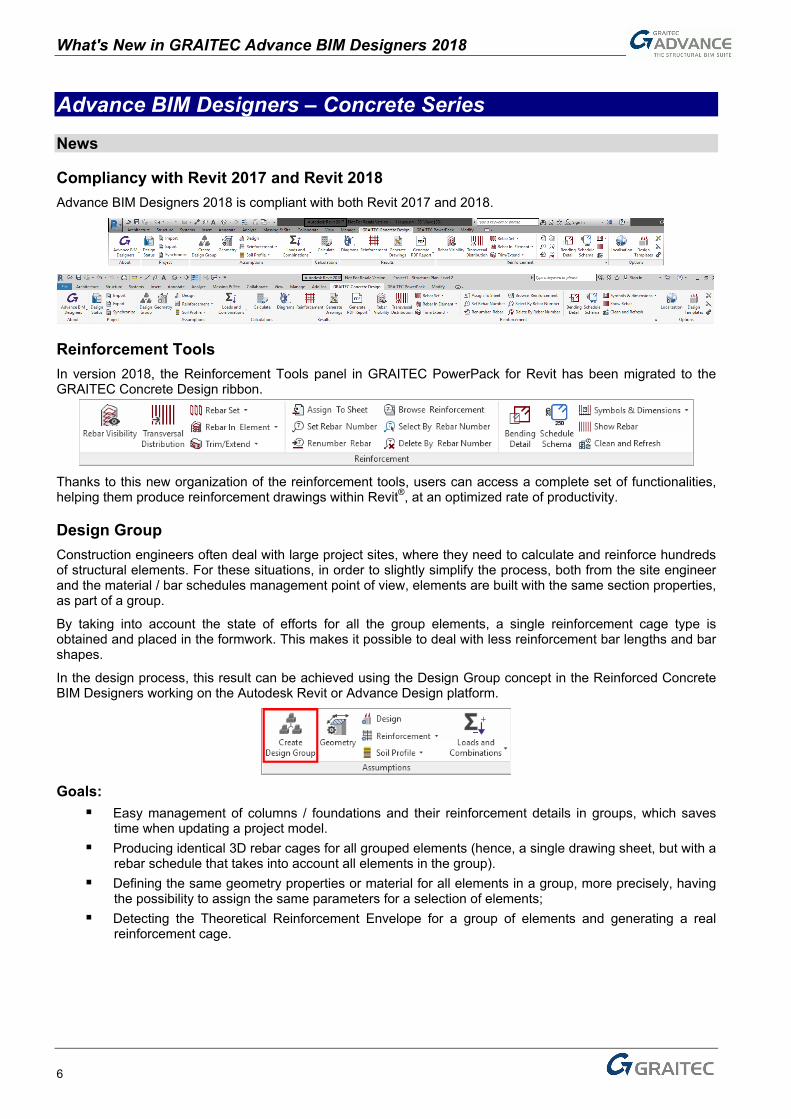
Infill panels for standard railings Aesthetical, functional, safe and very easy to create, the infill panels are now part of the GRAITEC Stair & Railing Designer. They can be used for guidance, support, and as protective barrier to prevent accidental falls.
The new Fillings option offers the possibility to create a panel between the posts inside the macro. Panels can be made of:
Pickets – two possibilities are available: Unframed panel (pickets created between two middle rails)

What's New in GRAITEC Advance BIM Designers 2018
34
Framed panel (pickets created inside a frame)
In both cases, several connections are available for pickets: aligned, cut, cut into.
Note: This option is not available for curved supports.
What's New in GRAITEC Advance BIM Designers 2018
35
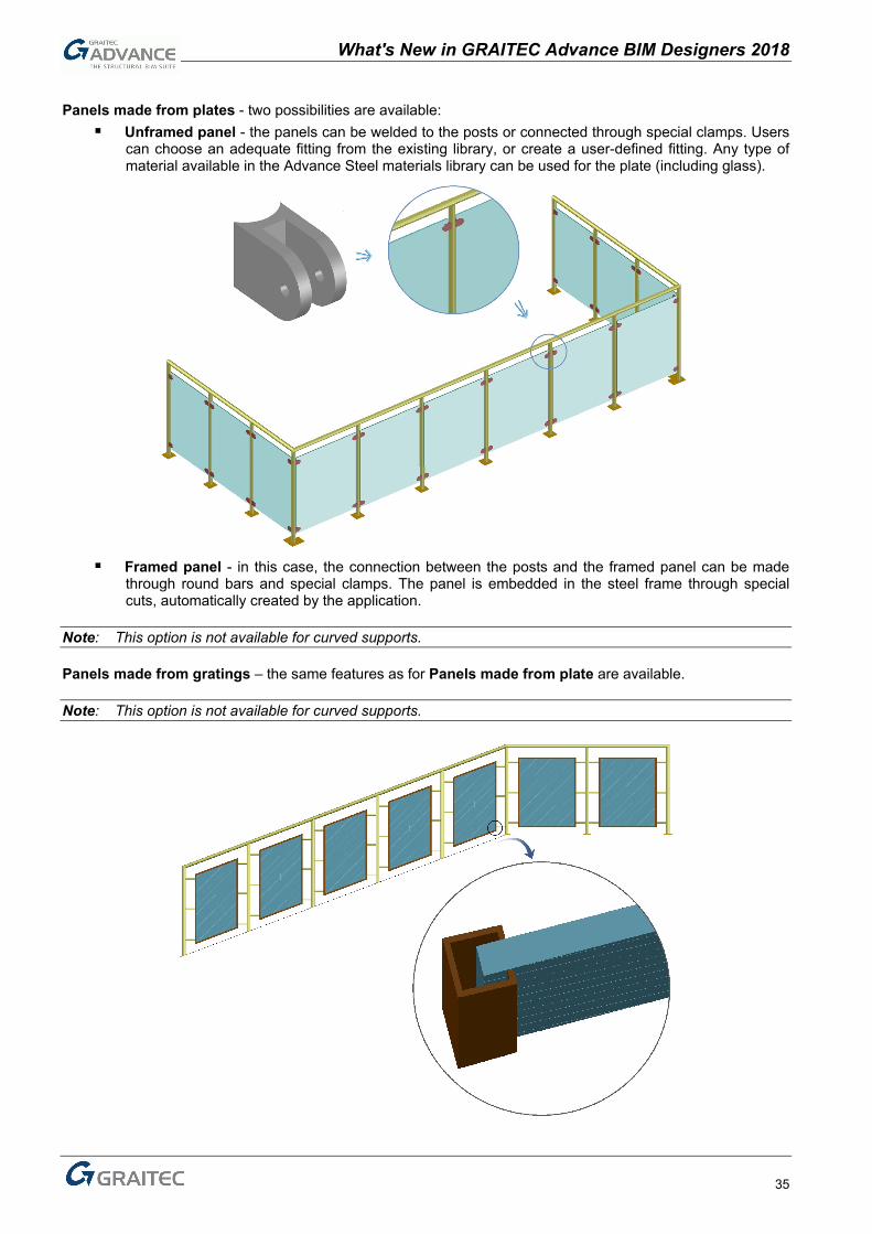
Panels made from plates - two possibilities are available: Unframed panel - the panels can be welded to the posts or connected through special clamps. Users
can choose an adequate fitting from the existing library, or create a user-defined fitting. Any type of material available in the Advance Steel materials library can be used for the plate (including glass).
Framed panel - in this case, the connection between the posts and the framed panel can be made
through round bars and special clamps. The panel is embedded in the steel frame through special cuts, automatically created by the application.
Note: This option is not available for curved supports.
Panels made from gratings – the same features as for Panels made from plate are available.
Note: This option is not available for curved supports.


What's New in GRAITEC Advance BIM Designers 2018
37
Key clamp railings Key clamp railings represent an alternative to the “classic” welded rails, with multiple advantages.
Their need appears because of the benefits in using them: no welding is necessary, so no qualified laborer is required; no special tools are needed to assembly them; the flexible system can be mounted quickly and easily on different site variations.
Several fittings are pre-configured from worldwide known producer Key Safety, and the users are able to edit and save any new fitting to match their requirements.
Note: This option is not available for curved supports.

What's New in GRAITEC Advance BIM Designers 2018
38
Improvements
“Double posts” for standard railing One major improvement for this version is the possibility to use double posts. This functionality was especially designer for flats sections and comes with special connections included.
Note: This option is not available for curved supports.
This will greatly expand the range of modeling possibilities.

What's New in GRAITEC Advance BIM Designers 2018
39
“Top handrail” disabled for standard railing The 2018 version comes with great flexibility. To accomplish this goal, another important improvement was added: the possibility to disable the top handrail and use a grab rail instead:
“Construction at top/ bottom end” of stringers for balanced stairs Starting with the 2018 version of the Stair & Railing Designer, the user can adjust the stringer ends by:
extending each side of the stringer with the desired value; creating a vertical / horizontal leg, depending on each case; automatically aligning the stringer to the horizontal support.