Embed Size (px)
Citation preview
What's New with Autodesk® Revit® 2013 Stairs and Railings? Paul F. Aubin Paul F. Aubin Consulting Services
AB2086 Perhaps you have heard that stairs and railings in Autodesk Revit 2013 software have gotten some significant new features. It's true! Stairs and railings sport many new features in this release. In this class, we will focus on a few new areas that should have an immediate positive effect on your stair and railing modeling workflow. Many commercial buildings include overlapping stairs, such as overlapping egress stairs. Using the new component-based stair, we will explore how we can now create an overlapping stair. Revit 2013 gives us ways to achieve such a stair without the common workarounds. With the new railing features, we can create handrails that include parametric railing extensions. Furthermore, handrails can now have true supports and returns (not balusters masquerading as supports). Stairs and railings are likely to remain an active area of development in future Revit releases, but don't let this stop you from exploring the many exciting possibilities that Revit 2013 presents right now.
Learning Objectives At the end of this class, you will be able to:
• Become acquainted with the new component-based stair
• Make an overlapping stair
• Explore the new railing handrail and guardrail features
• Add parametric supports and returns to railings
About the Speaker Paul F. Aubin is the author of many CAD and BIM book titles including the widely acclaimed: The Aubin Academy Mastering Series: Revit Architecture, AutoCAD Architecture, AutoCAD MEP and Revit MEP titles. Paul has also authored several video training courses for lynda.com (www.lynda.com/paulaubin). Paul is an independent architectural consultant who travels internationally providing Revit® Architecture and AutoCAD® Architecture implementation, training, and support services. Paul’s involvement in the architectural profession spans over 20 years, with experience that includes design, production, CAD management, mentoring, coaching and training. He is an active member of the Autodesk user community, and has been a top-rated speaker at Autodesk University (Autodesk’s annual user convention) for many years. Paul has also received high ratings at the Revit Technology Conference (RTC) in both the US and Australia and he spoke at the inaugural Central States Revit Workshop this year. His diverse experience in architectural firms, as a CAD manager, and as an educator gives his writing and his classroom instruction a fresh and credible focus. Paul is an associate member of the American Institute of Architects. He lives in Chicago with his wife and three children.
Contact me directly from the contact form at my website: www.paulaubin.com
What's New with Autodesk® Revit® 2013 Stairs and Railings?
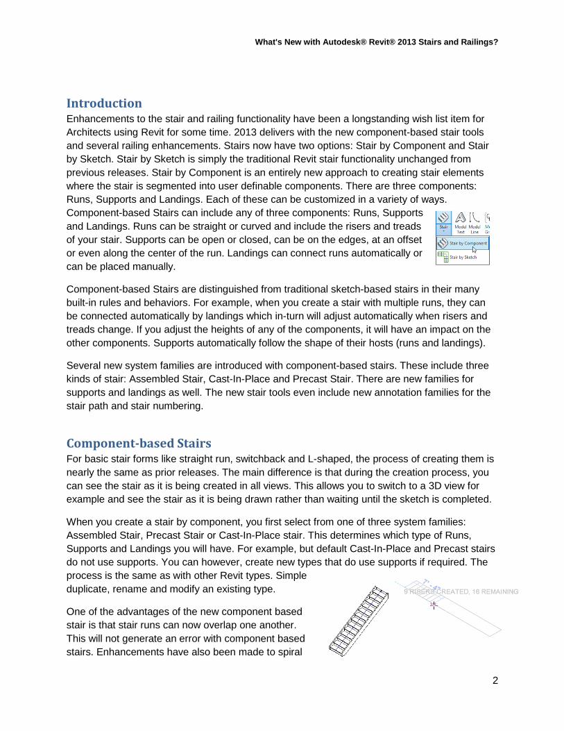
Introduction Enhancements to the stair and railing functionality have been a longstanding wish list item for Architects using Revit for some time. 2013 delivers with the new component-based stair tools and several railing enhancements. Stairs now have two options: Stair by Component and Stair by Sketch. Stair by Sketch is simply the traditional Revit stair functionality unchanged from previous releases. Stair by Component is an entirely new approach to creating stair elements where the stair is segmented into user definable components. There are three components: Runs, Supports and Landings. Each of these can be customized in a variety of ways. Component-based Stairs can include any of three components: Runs, Supports and Landings. Runs can be straight or curved and include the risers and treads of your stair. Supports can be open or closed, can be on the edges, at an offset or even along the center of the run. Landings can connect runs automatically or can be placed manually.
Component-based Stairs are distinguished from traditional sketch-based stairs in their many built-in rules and behaviors. For example, when you create a stair with multiple runs, they can be connected automatically by landings which in-turn will adjust automatically when risers and treads change. If you adjust the heights of any of the components, it will have an impact on the other components. Supports automatically follow the shape of their hosts (runs and landings).
Several new system families are introduced with component-based stairs. These include three kinds of stair: Assembled Stair, Cast-In-Place and Precast Stair. There are new families for supports and landings as well. The new stair tools even include new annotation families for the stair path and stair numbering.
Component-based Stairs For basic stair forms like straight run, switchback and L-shaped, the process of creating them is nearly the same as prior releases. The main difference is that during the creation process, you can see the stair as it is being created in all views. This allows you to switch to a 3D view for example and see the stair as it is being drawn rather than waiting until the sketch is completed.
When you create a stair by component, you first select from one of three system families: Assembled Stair, Precast Stair or Cast-In-Place stair. This determines which type of Runs, Supports and Landings you will have. For example, but default Cast-In-Place and Precast stairs do not use supports. You can however, create new types that do use supports if required. The process is the same as with other Revit types. Simple duplicate, rename and modify an existing type.
One of the advantages of the new component based stair is that stair runs can now overlap one another. This will not generate an error with component based stairs. Enhancements have also been made to spiral
2
What's New with Autodesk® Revit® 2013 Stairs and Railings?
stairs and we can now create stairs with winders. Winders are available in L-shaped and U-shaped configurations.
Supports replace stringers. Supports are a new system family and have their own types and type settings. A welcome enhancement that this brings is the ability to use a profile family for a support. This means that you can create supports that have the shape of a structural C channel for example. Profile families can also be used for both the treads and risers giving much more control over the shape of the stair’s various components than previously possible.
Component-based stairs offer many predefined configurations and settings that allow for many of the most common stair forms commonly constructed. Within this framework is flexibility is maintained so that many
custom stair configurations are also possible. However, in situations where the desired design cannot readily be achieved using component-based stairs, it is possible to convert a single run or a landing to a sketch-based component. This allows you to use the familiar sketch-based environment to create those custom configurations.
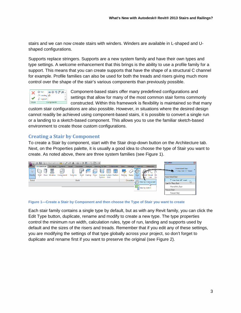
Creating a Stair by Component To create a Stair by component, start with the Stair drop-down button on the Architecture tab. Next, on the Properties palette, it is usually a good idea to choose the type of Stair you want to create. As noted above, there are three system families (see Figure 1).
Figure 1—Create a Stair by Component and then choose the Type of Stair you want to create
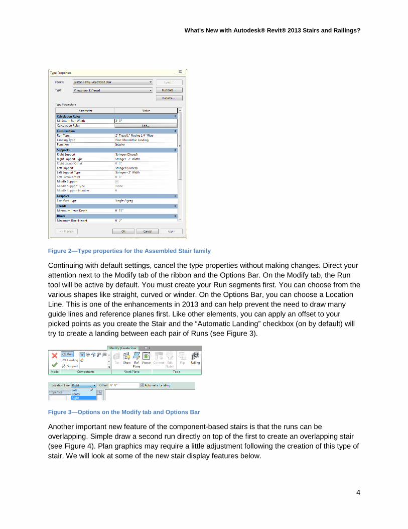
Each stair family contains a single type by default, but as with any Revit family, you can click the Edit Type button, duplicate, rename and modify to create a new type. The type properties control the minimum run width, calculation rules, type of run, landing and supports used by default and the sizes of the risers and treads. Remember that if you edit any of these settings, you are modifying the settings of that type globally across your project, so don’t forget to duplicate and rename first if you want to preserve the original (see Figure 2).
3
What's New with Autodesk® Revit® 2013 Stairs and Railings?
Figure 2—Type properties for the Assembled Stair family
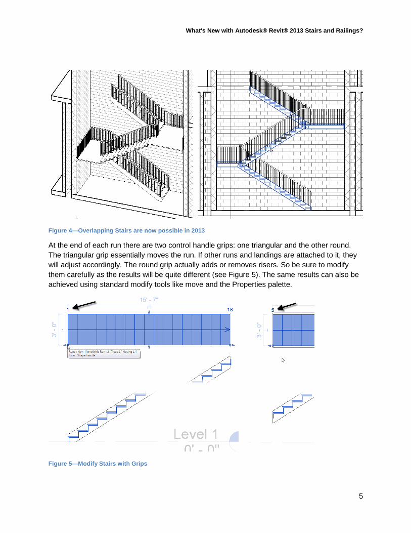
Continuing with default settings, cancel the type properties without making changes. Direct your attention next to the Modify tab of the ribbon and the Options Bar. On the Modify tab, the Run tool will be active by default. You must create your Run segments first. You can choose from the various shapes like straight, curved or winder. On the Options Bar, you can choose a Location Line. This is one of the enhancements in 2013 and can help prevent the need to draw many guide lines and reference planes first. Like other elements, you can apply an offset to your picked points as you create the Stair and the “Automatic Landing” checkbox (on by default) will try to create a landing between each pair of Runs (see Figure 3).
Figure 3—Options on the Modify tab and Options Bar
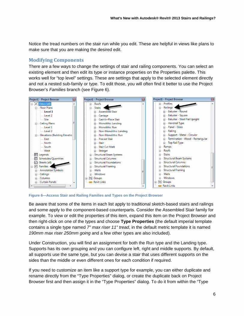
Another important new feature of the component-based stairs is that the runs can be overlapping. Simple draw a second run directly on top of the first to create an overlapping stair (see Figure 4). Plan graphics may require a little adjustment following the creation of this type of stair. We will look at some of the new stair display features below.
4
What's New with Autodesk® Revit® 2013 Stairs and Railings?
Figure 4—Overlapping Stairs are now possible in 2013
At the end of each run there are two control handle grips: one triangular and the other round. The triangular grip essentially moves the run. If other runs and landings are attached to it, they will adjust accordingly. The round grip actually adds or removes risers. So be sure to modify them carefully as the results will be quite different (see Figure 5). The same results can also be achieved using standard modify tools like move and the Properties palette.
Figure 5—Modify Stairs with Grips
5
What's New with Autodesk® Revit® 2013 Stairs and Railings?
Notice the tread numbers on the stair run while you edit. These are helpful in views like plans to make sure that you are making the desired edit.
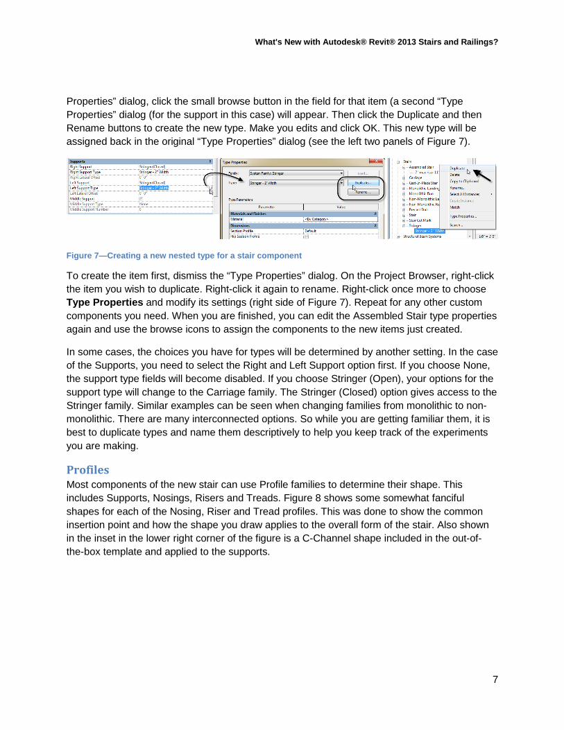
Modifying Components There are a few ways to change the settings of stair and railing components. You can select an existing element and then edit its type or instance properties on the Properties palette. This works well for “top level” settings. These are settings that apply to the selected element directly and not a nested sub-family or type. To edit those, you will often find it better to use the Project Browser’s Families branch (see Figure 6).
Figure 6—Access Stair and Railing Families and Types on the Project Browser
Be aware that some of the items in each list apply to traditional sketch-based stairs and railings and some apply to the component-based counterparts. Consider the Assembled Stair family for example. To view or edit the properties of this item, expand this item on the Project Browser and then right-click on one of the types and choose Type Properties (the default imperial template contains a single type named 7" max riser 11" tread, in the default metric template it is named 190mm max riser 250mm going and a few other types are also included).
Under Construction, you will find an assignment for both the Run type and the Landing type. Supports has its own grouping and you can configure left, right and middle supports. By default, all supports use the same type, but you can devise a stair that uses different supports on the sides than the middle or even different ones for each condition if required.
If you need to customize an item like a support type for example, you can either duplicate and rename directly from the “Type Properties” dialog, or create the duplicate back on Project Browser first and then assign it in the “Type Properties” dialog. To do it from within the “Type
6
What's New with Autodesk® Revit® 2013 Stairs and Railings?
Properties” dialog, click the small browse button in the field for that item (a second “Type Properties” dialog (for the support in this case) will appear. Then click the Duplicate and then Rename buttons to create the new type. Make you edits and click OK. This new type will be assigned back in the original “Type Properties” dialog (see the left two panels of Figure 7).
Figure 7—Creating a new nested type for a stair component
To create the item first, dismiss the “Type Properties” dialog. On the Project Browser, right-click the item you wish to duplicate. Right-click it again to rename. Right-click once more to choose Type Properties and modify its settings (right side of Figure 7). Repeat for any other custom components you need. When you are finished, you can edit the Assembled Stair type properties again and use the browse icons to assign the components to the new items just created.
In some cases, the choices you have for types will be determined by another setting. In the case of the Supports, you need to select the Right and Left Support option first. If you choose None, the support type fields will become disabled. If you choose Stringer (Open), your options for the support type will change to the Carriage family. The Stringer (Closed) option gives access to the Stringer family. Similar examples can be seen when changing families from monolithic to non-monolithic. There are many interconnected options. So while you are getting familiar them, it is best to duplicate types and name them descriptively to help you keep track of the experiments you are making.
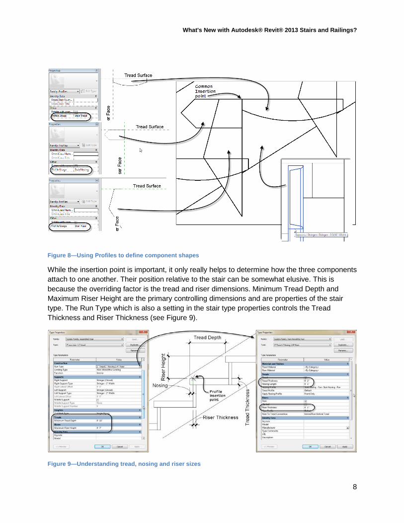
Profiles Most components of the new stair can use Profile families to determine their shape. This includes Supports, Nosings, Risers and Treads. Figure 8 shows some somewhat fanciful shapes for each of the Nosing, Riser and Tread profiles. This was done to show the common insertion point and how the shape you draw applies to the overall form of the stair. Also shown in the inset in the lower right corner of the figure is a C-Channel shape included in the out-of-the-box template and applied to the supports.
7
What's New with Autodesk® Revit® 2013 Stairs and Railings?
Figure 8—Using Profiles to define component shapes
While the insertion point is important, it only really helps to determine how the three components attach to one another. Their position relative to the stair can be somewhat elusive. This is because the overriding factor is the tread and riser dimensions. Minimum Tread Depth and Maximum Riser Height are the primary controlling dimensions and are properties of the stair type. The Run Type which is also a setting in the stair type properties controls the Tread Thickness and Riser Thickness (see Figure 9).
Figure 9—Understanding tread, nosing and riser sizes
8
What's New with Autodesk® Revit® 2013 Stairs and Railings?
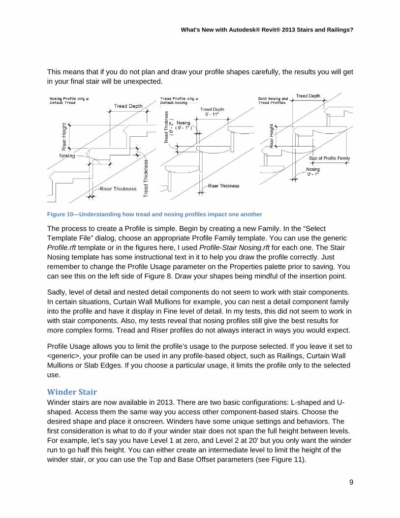
This means that if you do not plan and draw your profile shapes carefully, the results you will get in your final stair will be unexpected.
Figure 10—Understanding how tread and nosing profiles impact one another
The process to create a Profile is simple. Begin by creating a new Family. In the “Select Template File” dialog, choose an appropriate Profile Family template. You can use the generic Profile.rft template or in the figures here, I used Profile-Stair Nosing.rft for each one. The Stair Nosing template has some instructional text in it to help you draw the profile correctly. Just remember to change the Profile Usage parameter on the Properties palette prior to saving. You can see this on the left side of Figure 8. Draw your shapes being mindful of the insertion point.
Sadly, level of detail and nested detail components do not seem to work with stair components. In certain situations, Curtain Wall Mullions for example, you can nest a detail component family into the profile and have it display in Fine level of detail. In my tests, this did not seem to work in with stair components. Also, my tests reveal that nosing profiles still give the best results for more complex forms. Tread and Riser profiles do not always interact in ways you would expect.
Profile Usage allows you to limit the profile’s usage to the purpose selected. If you leave it set to <generic>, your profile can be used in any profile-based object, such as Railings, Curtain Wall Mullions or Slab Edges. If you choose a particular usage, it limits the profile only to the selected use.
Winder Stair Winder stairs are now available in 2013. There are two basic configurations: L-shaped and U-shaped. Access them the same way you access other component-based stairs. Choose the desired shape and place it onscreen. Winders have some unique settings and behaviors. The first consideration is what to do if your winder stair does not span the full height between levels. For example, let’s say you have Level 1 at zero, and Level 2 at 20' but you only want the winder run to go half this height. You can either create an intermediate level to limit the height of the winder stair, or you can use the Top and Base Offset parameters (see Figure 11).
9
What's New with Autodesk® Revit® 2013 Stairs and Railings?
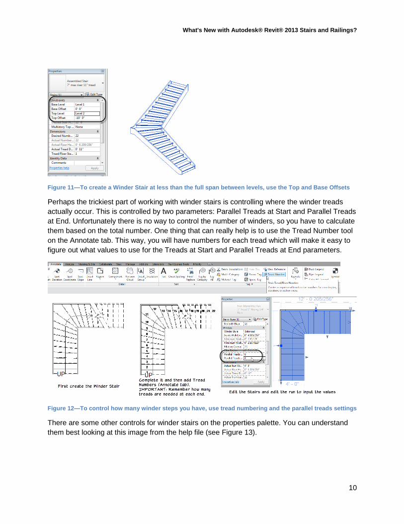
Figure 11—To create a Winder Stair at less than the full span between levels, use the Top and Base Offsets
Perhaps the trickiest part of working with winder stairs is controlling where the winder treads actually occur. This is controlled by two parameters: Parallel Treads at Start and Parallel Treads at End. Unfortunately there is no way to control the number of winders, so you have to calculate them based on the total number. One thing that can really help is to use the Tread Number tool on the Annotate tab. This way, you will have numbers for each tread which will make it easy to figure out what values to use for the Treads at Start and Parallel Treads at End parameters.
Figure 12—To control how many winder steps you have, use tread numbering and the parallel treads settings
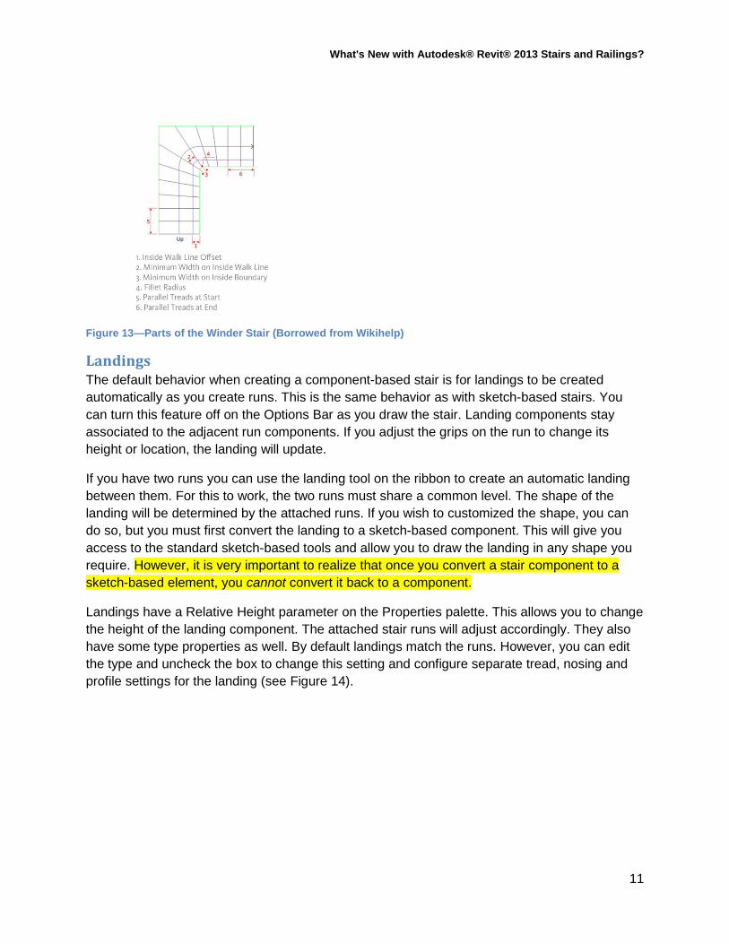
There are some other controls for winder stairs on the properties palette. You can understand them best looking at this image from the help file (see Figure 13).
10
What's New with Autodesk® Revit® 2013 Stairs and Railings?
Figure 13—Parts of the Winder Stair (Borrowed from Wikihelp)
Landings The default behavior when creating a component-based stair is for landings to be created automatically as you create runs. This is the same behavior as with sketch-based stairs. You can turn this feature off on the Options Bar as you draw the stair. Landing components stay associated to the adjacent run components. If you adjust the grips on the run to change its height or location, the landing will update.
If you have two runs you can use the landing tool on the ribbon to create an automatic landing between them. For this to work, the two runs must share a common level. The shape of the landing will be determined by the attached runs. If you wish to customized the shape, you can do so, but you must first convert the landing to a sketch-based component. This will give you access to the standard sketch-based tools and allow you to draw the landing in any shape you require. However, it is very important to realize that once you convert a stair component to a sketch-based element, you cannot convert it back to a component.
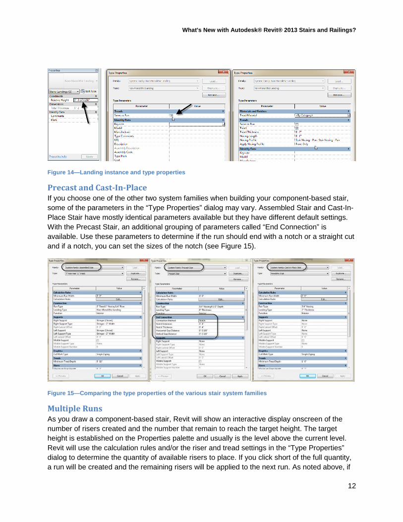
Landings have a Relative Height parameter on the Properties palette. This allows you to change the height of the landing component. The attached stair runs will adjust accordingly. They also have some type properties as well. By default landings match the runs. However, you can edit the type and uncheck the box to change this setting and configure separate tread, nosing and profile settings for the landing (see Figure 14).
11
What's New with Autodesk® Revit® 2013 Stairs and Railings?
Figure 14—Landing instance and type properties
Precast and Cast-In-Place If you choose one of the other two system families when building your component-based stair, some of the parameters in the “Type Properties” dialog may vary. Assembled Stair and Cast-In-Place Stair have mostly identical parameters available but they have different default settings. With the Precast Stair, an additional grouping of parameters called “End Connection” is available. Use these parameters to determine if the run should end with a notch or a straight cut and if a notch, you can set the sizes of the notch (see Figure 15).
Figure 15—Comparing the type properties of the various stair system families
Multiple Runs As you draw a component-based stair, Revit will show an interactive display onscreen of the number of risers created and the number that remain to reach the target height. The target height is established on the Properties palette and usually is the level above the current level. Revit will use the calculation rules and/or the riser and tread settings in the “Type Properties” dialog to determine the quantity of available risers to place. If you click short of the full quantity, a run will be created and the remaining risers will be applied to the next run. As noted above, if
12
What's New with Autodesk® Revit® 2013 Stairs and Railings?
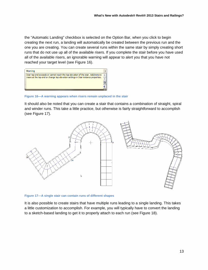
the “Automatic Landing” checkbox is selected on the Option Bar, when you click to begin creating the next run, a landing will automatically be created between the previous run and the one you are creating. You can create several runs within the same stair by simply creating short runs that do not use up all of the available risers. If you complete the stair before you have used all of the available risers, an ignorable warning will appear to alert you that you have not reached your target level (see Figure 16).
Figure 16—A warning appears when risers remain unplaced in the stair
It should also be noted that you can create a stair that contains a combination of straight, spiral and winder runs. This take a little practice, but otherwise is fairly straightforward to accomplish (see Figure 17).
Figure 17—A single stair can contain runs of different shapes
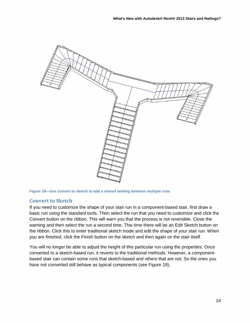
It is also possible to create stairs that have multiple runs leading to a single landing. This takes a little customization to accomplish. For example, you will typically have to convert the landing to a sketch-based landing to get it to properly attach to each run (see Figure 18).
13
What's New with Autodesk® Revit® 2013 Stairs and Railings?
Figure 18—Use convert to sketch to add a shared landing between multiple runs
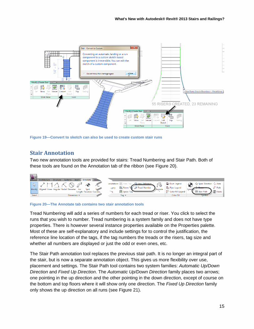
Convert to Sketch If you need to customize the shape of your stair run in a component-based stair, first draw a basic run using the standard tools. Then select the run that you need to customize and click the Convert button on the ribbon. This will warn you that the process is not reversible. Close the warning and then select the run a second time. This time there will be an Edit Sketch button on the ribbon. Click this to enter traditional sketch mode and edit the shape of your stair run. When you are finished, click the Finish button on the sketch and then again on the stair itself.
You will no longer be able to adjust the height of this particular run using the properties. Once converted to a sketch-based run, it reverts to the traditional methods. However, a component-based stair can contain some runs that sketch-based and others that are not. So the ones you have not converted still behave as typical components (see Figure 19).
14
What's New with Autodesk® Revit® 2013 Stairs and Railings?
Figure 19—Convert to sketch can also be used to create custom stair runs
Stair Annotation Two new annotation tools are provided for stairs: Tread Numbering and Stair Path. Both of these tools are found on the Annotation tab of the ribbon (see Figure 20).
Figure 20—The Annotate tab contains two stair annotation tools
Tread Numbering will add a series of numbers for each tread or riser. You click to select the runs that you wish to number. Tread numbering is a system family and does not have type properties. There is however several instance properties available on the Properties palette. Most of these are self-explanatory and include settings for to control the justification, the reference line location of the tags, if the tag numbers the treads or the risers, tag size and whether all numbers are displayed or just the odd or even ones, etc.
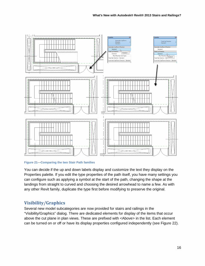
The Stair Path annotation tool replaces the previous stair path. It is no longer an integral part of the stair, but is now a separate annotation object. This gives us more flexibility over use, placement and settings. The Stair Path tool contains two system families: Automatic Up/Down Direction and Fixed Up Direction. The Automatic Up/Down Direction family places two arrows; one pointing in the up direction and the other pointing in the down direction, except of course on the bottom and top floors where it will show only one direction. The Fixed Up Direction family only shows the up direction on all runs (see Figure 21).
15
What's New with Autodesk® Revit® 2013 Stairs and Railings?
Figure 21—Comparing the two Stair Path families
You can decide if the up and down labels display and customize the text they display on the Properties palette. If you edit the type properties of the path itself, you have many settings you can configure such as applying a symbol at the start of the path, changing the shape at the landings from straight to curved and choosing the desired arrowhead to name a few. As with any other Revit family, duplicate the type first before modifying to preserve the original.
Visibility/Graphics Several new model subcategories are now provided for stairs and railings in the “Visibility/Graphics” dialog. There are dedicated elements for display of the items that occur above the cut plane in plan views. These are prefixed with <Above> in the list. Each element can be turned on or off or have its display properties configured independently (see Figure 22).
16

What's New with Autodesk® Revit® 2013 Stairs and Railings?
Figure 22—Stairs and Railings have several <Above> subcategories in Visibility/Graphics
On the Annotation Categories tab of the “Visibility/Graphics Overrides dialog you will also find settings for the Stair Paths category and it too has several subcategories including an <Above> component for Up Arrows.
Railing Enhancements Railings have also received a major overhaul in this release. Railings can still be created automatically when creating a stair or drawn independently. The changes to railings occur in the structure of the railing itself. Railings now have new subcomponents for Top Rails, Handrails and Supports. We can even add rail extensions and returns at the start and end of each railing. You configure these features in the railing type properties dialog and in the type properties of the new Top Rail and Handrail system families. The railing type properties still contain the familiar Rail Structure and Baluster Placement dialogs for compatibility with previous releases. But the new Top and Handrail settings are also included. To choose one of these, you should first expand the Families branch of the Project Browser and look beneath the Railings entry. There you will find Top Rail and Handrail Types. You can duplicate or modify existing ones and configure their shape, offsets and extension settings. You can even add new termination families at the ends of the handrails. The new Handrail types can be added to either side of the railing and can include parametrically repeated Support families along the length of the handrail.
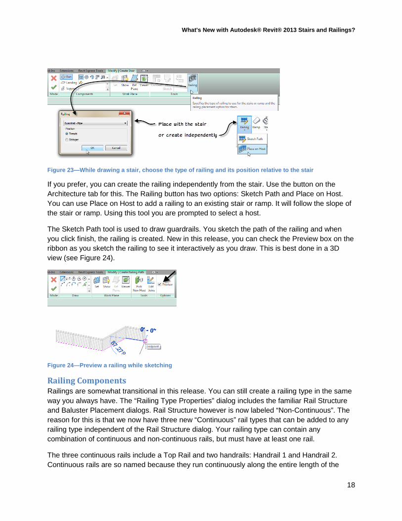
The easiest way to place a railing continues to be to place it with a stair. On the Modify|Create Stair tab, there is a Railing button. Click this to choose the type of railing that you wish to create with the stair. In addition to choosing the type of railing, we can now decide to position the railing on the treads or the stringer of the stair (see Figure 23).
17
What's New with Autodesk® Revit® 2013 Stairs and Railings?
Figure 23—While drawing a stair, choose the type of railing and its position relative to the stair
If you prefer, you can create the railing independently from the stair. Use the button on the Architecture tab for this. The Railing button has two options: Sketch Path and Place on Host. You can use Place on Host to add a railing to an existing stair or ramp. It will follow the slope of the stair or ramp. Using this tool you are prompted to select a host.
The Sketch Path tool is used to draw guardrails. You sketch the path of the railing and when you click finish, the railing is created. New in this release, you can check the Preview box on the ribbon as you sketch the railing to see it interactively as you draw. This is best done in a 3D view (see Figure 24).
Figure 24—Preview a railing while sketching
Railing Components Railings are somewhat transitional in this release. You can still create a railing type in the same way you always have. The “Railing Type Properties” dialog includes the familiar Rail Structure and Baluster Placement dialogs. Rail Structure however is now labeled “Non-Continuous”. The reason for this is that we now have three new “Continuous” rail types that can be added to any railing type independent of the Rail Structure dialog. Your railing type can contain any combination of continuous and non-continuous rails, but must have at least one rail.
The three continuous rails include a Top Rail and two handrails: Handrail 1 and Handrail 2. Continuous rails are so named because they run continuously along the entire length of the
18
What's New with Autodesk® Revit® 2013 Stairs and Railings?
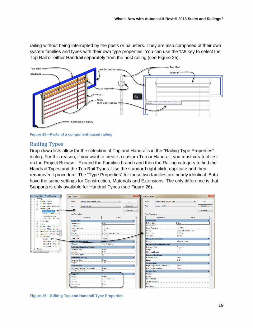
railing without being interrupted by the posts or balusters. They are also composed of their own system families and types with their own type properties. You can use the TAB key to select the Top Rail or either Handrail separately from the host railing (see Figure 25).
Figure 25—Parts of a component-based railing
Railing Types Drop-down lists allow for the selection of Top and Handrails in the “Railing Type Properties” dialog. For this reason, if you want to create a custom Top or Handrail, you must create it first on the Project Browser. Expand the Families branch and then the Railing category to find the Handrail Types and the Top Rail Types. Use the standard right-click, duplicate and then rename/edit procedure. The “Type Properties” for these two families are nearly identical. Both have the same settings for Construction, Materials and Extensions. The only difference is that Supports is only available for Handrail Types (see Figure 26).
Figure 26—Editing Top and Handrail Type Properties
19
What's New with Autodesk® Revit® 2013 Stairs and Railings?
Both kinds of rail use standard Revit Profile families for their shape. Hand Clearance determines the offset distance from the railing sketch line. The Handrail type also has a height parameter. Top Rails appear at the top of the railing so they do not have this parameter. There are also a few choices for default join and transitions. Transitions mostly apply on railings used for stairs.
Railing Supports Railing supports are a new family that can be repeated along the length of a Handrail. The default template contains a single example family. However, the Support family is a component family, so you can build your own support families in the family editor. This combined with the wide variety of Layout options opens up nearly endless possibilities.
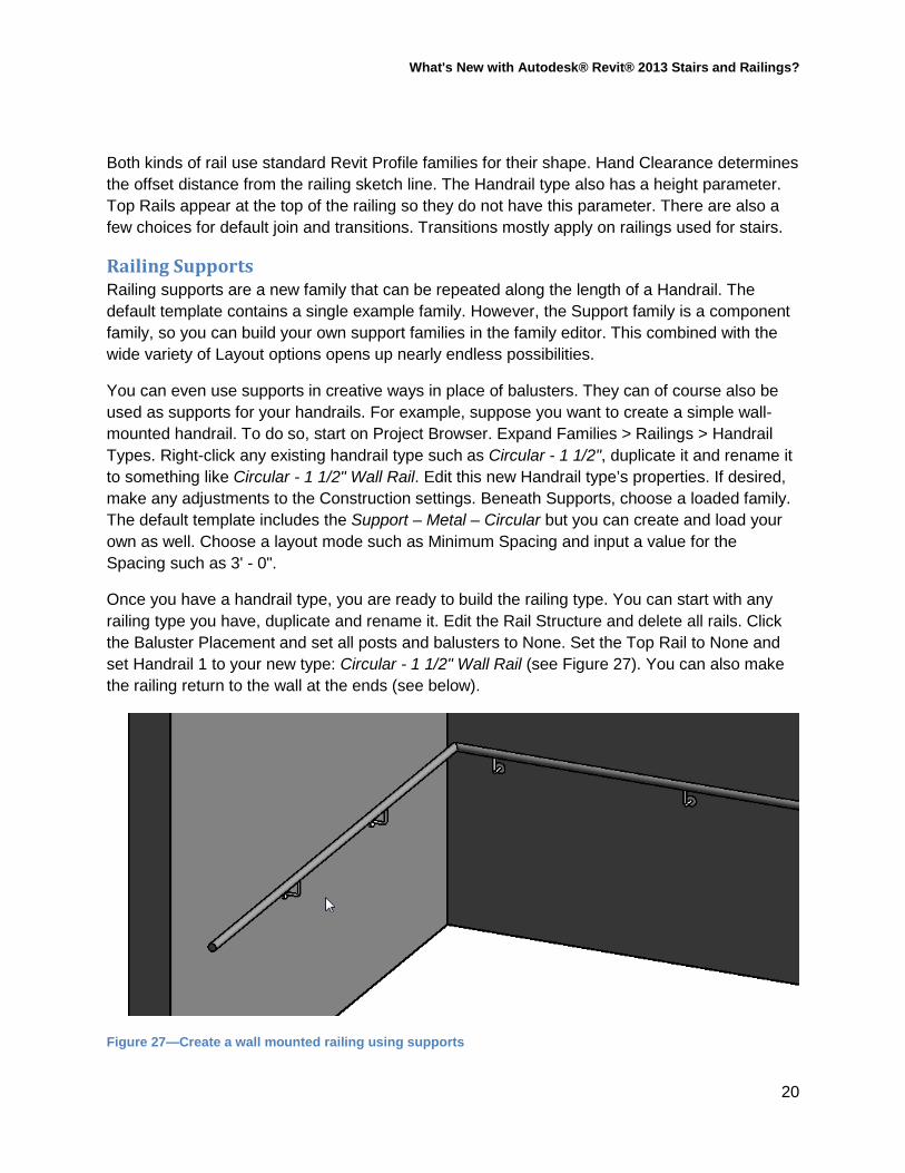
You can even use supports in creative ways in place of balusters. They can of course also be used as supports for your handrails. For example, suppose you want to create a simple wall-mounted handrail. To do so, start on Project Browser. Expand Families > Railings > Handrail Types. Right-click any existing handrail type such as Circular - 1 1/2", duplicate it and rename it to something like Circular - 1 1/2" Wall Rail. Edit this new Handrail type’s properties. If desired, make any adjustments to the Construction settings. Beneath Supports, choose a loaded family. The default template includes the Support – Metal – Circular but you can create and load your own as well. Choose a layout mode such as Minimum Spacing and input a value for the Spacing such as 3' - 0".
Once you have a handrail type, you are ready to build the railing type. You can start with any railing type you have, duplicate and rename it. Edit the Rail Structure and delete all rails. Click the Baluster Placement and set all posts and balusters to None. Set the Top Rail to None and set Handrail 1 to your new type: Circular - 1 1/2" Wall Rail (see Figure 27). You can also make the railing return to the wall at the ends (see below).
Figure 27—Create a wall mounted railing using supports
20
What's New with Autodesk® Revit® 2013 Stairs and Railings?
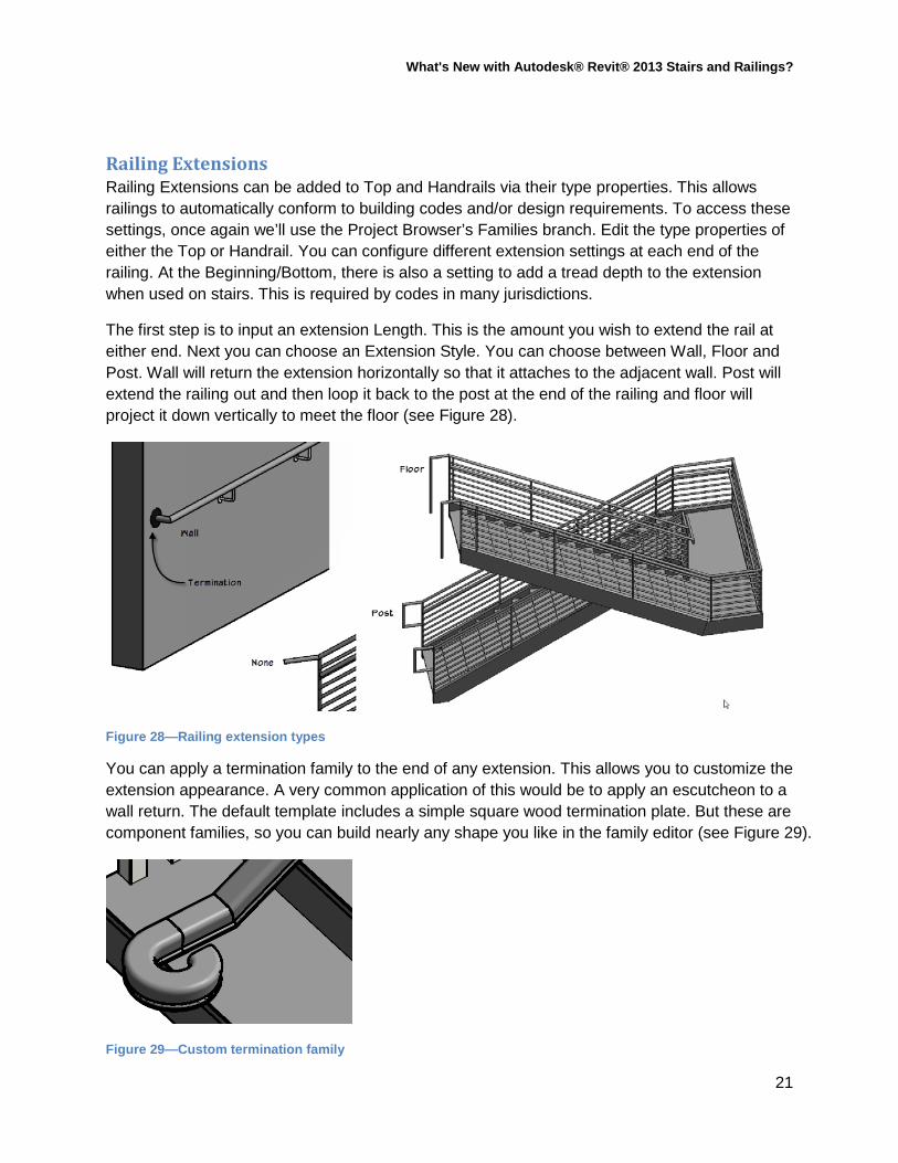
Railing Extensions Railing Extensions can be added to Top and Handrails via their type properties. This allows railings to automatically conform to building codes and/or design requirements. To access these settings, once again we’ll use the Project Browser’s Families branch. Edit the type properties of either the Top or Handrail. You can configure different extension settings at each end of the railing. At the Beginning/Bottom, there is also a setting to add a tread depth to the extension when used on stairs. This is required by codes in many jurisdictions.
The first step is to input an extension Length. This is the amount you wish to extend the rail at either end. Next you can choose an Extension Style. You can choose between Wall, Floor and Post. Wall will return the extension horizontally so that it attaches to the adjacent wall. Post will extend the railing out and then loop it back to the post at the end of the railing and floor will project it down vertically to meet the floor (see Figure 28).
Figure 28—Railing extension types
You can apply a termination family to the end of any extension. This allows you to customize the extension appearance. A very common application of this would be to apply an escutcheon to a wall return. The default template includes a simple square wood termination plate. But these are component families, so you can build nearly any shape you like in the family editor (see Figure 29).
Figure 29—Custom termination family
21
What's New with Autodesk® Revit® 2013 Stairs and Railings?
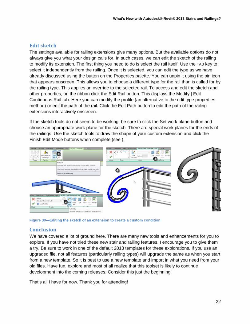
Edit sketch The settings available for railing extensions give many options. But the available options do not always give you what your design calls for. In such cases, we can edit the sketch of the railing to modify its extension. The first thing you need to do is select the rail itself. Use the TAB key to select it independently from the railing. Once it is selected, you can edit the type as we have already discussed using the button on the Properties palette. You can unpin it using the pin icon that appears onscreen. This allows you to choose a different type for the rail than is called for by the railing type. This applies an override to the selected rail. To access and edit the sketch and other properties, on the ribbon click the Edit Rail button. This displays the Modify | Edit Continuous Rail tab. Here you can modify the profile (an alternative to the edit type properties method) or edit the path of the rail. Click the Edit Path button to edit the path of the railing extensions interactively onscreen.
If the sketch tools do not seem to be working, be sure to click the Set work plane button and choose an appropriate work plane for the sketch. There are special work planes for the ends of the railings. Use the sketch tools to draw the shape of your custom extension and click the Finish Edit Mode buttons when complete (see ).
Figure 30—Editing the sketch of an extension to create a custom condition
Conclusion We have covered a lot of ground here. There are many new tools and enhancements for you to explore. If you have not tried these new stair and railing features, I encourage you to give them a try. Be sure to work in one of the default 2013 templates for these explorations. If you use an upgraded file, not all features (particularly railing types) will upgrade the same as when you start from a new template. So it is best to use a new template and import in what you need from your old files. Have fun, explore and most of all realize that this toolset is likely to continue development into the coming releases. Consider this just the beginning!
That’s all I have for now. Thank you for attending!
22
What's New with Autodesk® Revit® 2013 Stairs and Railings?
Please feel free to experiment further. Thank you for attending.
Further Study You can find more information and tutorials in The Aubin Academy Master Series: Revit Architecture. Chapter 7 is devoted to vertical circulation including sketch-based Stairs, Component Stairs and new Railing features.
I also have Revit video training available at: www.lynda.com/trial/paubin. I have five courses at lynda.com:
Revit Essentials (2011 and 2013), Revit Family Editor, Revit Architecture Rendering and Advanced Modeling in Revit Architecture.
Revit Essentials has some coverage of Stairs and Railings. Component-based Stairs are not covered at this time, but Railing Extensions are covered
in Revit Essential Training 2013. Advanced Modeling has a custom sketch-based stair exercise.
Blog Posts on Stairs and Railings:
http://whatrevitwants.blogspot.com/2012/09/component-based-stairs-training.html
http://whatrevitwants.blogspot.com/2012/11/railing-families-november-2012.html
http://whatrevitwants.blogspot.com/2012/10/revit-2013-railings-almost-7-months-old.html
If you have any questions about this session or Revit in general, you can use the contact form at www.paulaubin.com to send me an email.
Follow me on titter: @paulfaubin
Thank you for attending. Please fill out your evaluation.
23