Embed Size (px)
Citation preview
arX
iv:1
007.
2204
v1 [
cs.G
R]
13
Jul 2
010
What’s wrong with Phong
- Designers’ appraisal of shading in
CAD-systems
Jorg M. Hahn∗
The Phong illumination model is still widely used in realtime 3D visualiza-tion systems. The aim of this article is to document problems with the Phongillumination model that are encountered by an important professional usergroup, namely digital designers. This leads to a visual evaluation of Phongillumination, which at least in this condensed form seems still to be missingin the literature. It is hoped that by explicating these flaws, awareness aboutthe limitations and interdependencies of the model will increase, both amongfellow users, and among researchers and developers.
1 Introduction
The Phong illumination model, due to its simplicity and ability to model a range of ma-terial appearances, has become one of the most widely used shader models in computergraphics. Nevertheless, it is well known that it has certain shortfalls.
In the original paper [Phong, 1975] no physical justification was given nor indeedintended. Later it was noted that it is not physically plausible, e.g Helmholtz reci-procity and energy conservation are not met [Lewis, 1994]. And in the perception lit-erature, the physically unrealistic appearance has been noted, e.g. [Parker et al., 1992],[Johnston and Curran, 1996], [Koenderink and van Doorn, 2003], although it is still com-monly used in psychophysical experiments.
∗Daimler AG, Design - Data and Models, Sindelfingen, Germany, joerg.hahn(at)daimler.com. Thispaper was written 2006-2007. The author thanks the designers at Mercedes-Benz who were criticalof their digital renderings, and who helped with observations and comments. The author gratefullyacknowledges feedback and encouragement from Konrad Polthier of Freie Universitat Berlin, andfrom Roland Fleming of the Max Planck Institute for Biological Cybernetics in Tubingen.
1
Jorg M. Hahn
And it is still predominant in CAD-systems. The common graphics interfaces, OpenGLand DirectX, employ the Phong illumination model. And thus it is encountered by mostif not all users who create digital 3D models.
Industrial Design today makes heavy use of digital means to materialize ideas. Thefinal product is a real (physical) object. In this respect, design differs from other promi-nent areas of digital rendering, e.g. the games and movie industries, where only thevisual appearance of the digital model counts.
In particular in the automotive industries there is a well established division of labourbetween designers1 and modellers. Roughly speaking, the designer sketches ideas (mainlyin 2D) and the modeller builds a 3D model, either physical or digital. Then it is thetask of the designer to look at, perceive and understand the model built by the modellerand then to refine his sketches to direct the further evolution of the model.
The appraisal of digital models and physical models is a vital skill for a designer. Thereis hardly any other user group that looks at digital models as carefully and critically asdesigners do2. Their observations and impressions can give valuable input to computergraphics research.
There seems to be surprisingly little research on how designers appraise digital models.An exception is [Ferwerda et al., 2004], which describes an experiment with color frogs,which are generic car-like shapes. They found that the rendering method used had asignificant effect on the ability to discriminate color frogs that differed subtly in shape,and global illumination rendering improved sensitivity to shape differences.
On the other hand, Greg Ward, the author of the Radiance lighting simulation and ren-dering system [Ward, 1994], emphasizes the importance of the local illumination modelfor realistic appearance of digital renderings [Ward, 2001], [Ward, 2003], but suspectsthat this still seems to be poorly understood.
Occasional complaints of CAD modellers about the apparent form of shaded imagesof their digital models, and some surprise of designers when looking at a physical modelmilled from digital data, gave reason for an investigation of digital models and theirdisplay in the CAD-systems concerned. In fact, a stark statement from an embarrasseddesigner, the digital model looks like a cardboard box, imposed the question, what makesa nicely curved surface look like a cardboard box, and thus gave the ignition.
The CAD-systems employed were Alias StudioTools V12 with its products AutoStudioand SurfaceStudio, CATIA V5R13, and ICEM Surf V4.3, which are widely used in theautomotive industries for modelling, and an in-house system, DBView/veo, a real timevisualization system based on OpenInventor which is mainly used for design evaluationby designers. In working sessions a designer often joins a modeller working in ICEM
1 The term design refers to conceptual design or styling as opposed to engineering design.2 It seems that the modellers have a much better understanding of their models. But their understandingof the model is less based on the visual appearance. They rely much more on wire-frame display(iso-parameter lines) or diagnostics (e.g. section lines, isophotes). And they interact longer and moreintensively with the digital model.
2
What’s wrong with Phong
or Alias and sees the display of these systems. CATIA was added mainly due to itsimportance for automotive engineers.
It soon turned out that illumination was a main issue of concern, and the questionwas, how to evaluate or understand this concern. So an idea emerged to conduct ahands-on experiment with some designers. In the course of this investigations otherflaws of the illumination were found or re-discovered. This led to a visual evaluation ofPhong illumination, which at least in this condensed form seems - more than 30 yearsafter its origin - still to be missing in the literature.
The aim of this article is to document the problems with the Phong model that areencountered by an important professional user group, namely digital designers. It ishoped that by explicating these flaws, awareness about the limitations and interdepen-dencies of the model will increase, both among fellow users, and among researchers anddevelopers.
This paper is organized as follows. Section 2 shows an experiment with designers onshape perception with different lighting conditions. Section 3 looks on some (more orless known) effects of Phong illumination and highlights that are visible to designers,and discusses their impact on form appraisal. Section 4 deals with the behaviour oflight and material and related effects that are visible to and experienced by designers.Finally, section 5 summarizes the conclusions.
2 Form appraisal - an experiment with designers
In a workshop with a group of automotive designers, the designers were given some tasksinvolving digital images. The images were presented on a powerwall. The designers wereall familar with digital presentations of digital models.
2.1 Model selection - ball
The selection of a single favorite from a set of candidate models is a typical task in thedesign process. Thus the designers were shown digital renderings of a sphere, see fig. 1.
The task was to select the best sphere. Every designer could stick two bullets on aboard for his favorite3.
A sphere was chosen as stimulus because everybody knows what the shape is meantto look like and thus can comment how his percept of a picture matches this imaginedshape. A second reason was that it can serve as a probe for the illumination, i.e. the lightsources, although not seen directly in the picture, can be explained from their reflec-tion on the sphere. However, the sphere has certain properties (symmetries, curvature,
3 Such voting is used in business meetings, although it is a scientifically insufficient, due to possiblecross-influences
3
Jorg M. Hahn
(a)
(b)
(c)
(d)
(e)
(a)
(b)
(c)
(d)
(e)
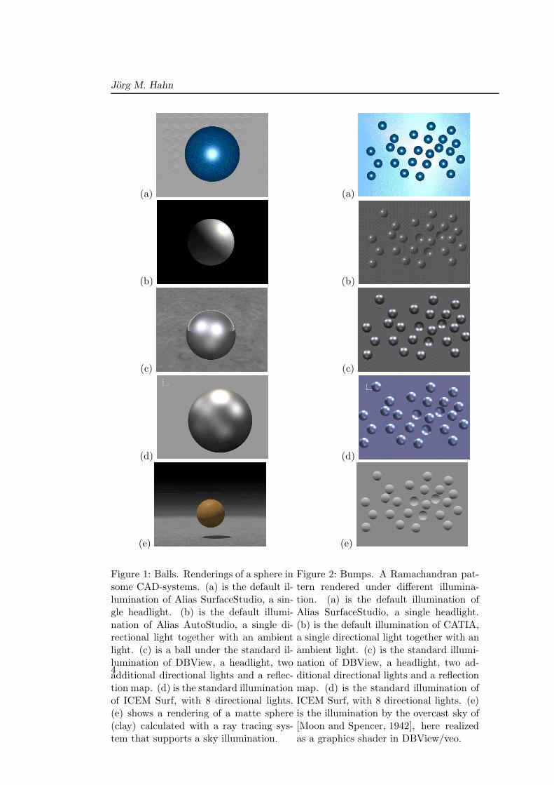
Figure 1: Balls. Renderings of a sphere insome CAD-systems. (a) is the default il-lumination of Alias SurfaceStudio, a sin-gle headlight. (b) is the default illumi-nation of Alias AutoStudio, a single di-rectional light together with an ambientlight. (c) is a ball under the standard il-lumination of DBView, a headlight, twoadditional directional lights and a reflec-tion map. (d) is the standard illuminationof ICEM Surf, with 8 directional lights.(e) shows a rendering of a matte sphere(clay) calculated with a ray tracing sys-tem that supports a sky illumination.
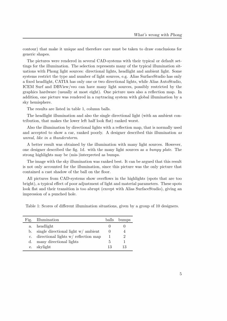
Figure 2: Bumps. A Ramachandran pat-tern rendered under different illumina-tion. (a) is the default illumination ofAlias SurfaceStudio, a single headlight.(b) is the default illumination of CATIA,a single directional light together with anambient light. (c) is the standard illumi-nation of DBView, a headlight, two ad-ditional directional lights and a reflectionmap. (d) is the standard illumination ofICEM Surf, with 8 directional lights. (e)is the illumination by the overcast sky of[Moon and Spencer, 1942], here realizedas a graphics shader in DBView/veo.
4
What’s wrong with Phong
contour) that make it unique and therefore care must be taken to draw conclusions forgeneric shapes.
The pictures were rendered in several CAD-systems with their typical or default set-tings for the illumination. The selection represents many of the typical illumination sit-uations with Phong light sources: directional lights, headlight and ambient light. Somesystems restrict the type and number of light sources, e.g. Alias SurfaceStudio has onlya fixed headlight, CATIA has only one or two directional lights, while Alias AutoStudio,ICEM Surf and DBView/veo can have many light sources, possibly restricted by thegraphics hardware (usually at most eight). One picture uses also a reflection map. Inaddition, one picture was rendered in a raytracing system with global illumination by asky hemisphere.
The results are listed in table 1, column balls.
The headlight illumination and also the single directional light (with an ambient con-tribution, that makes the lower left half look flat) ranked worst.
Also the illumination by directional lights with a reflection map, that is normally usedand accepted to show a car, ranked poorly. A designer described this illumination asunreal, like in a thunderstorm.
A better result was obtained by the illumination with many light sources. However,one designer described the fig. 1d. with the many light sources as a bumpy plate. Thestrong highlights may be (mis-)interpreted as bumps.
The image with the sky illumination was ranked best. It can be argued that this resultis not only accounted for the illumination, since this picture was the only picture thatcontained a cast shadow of the ball on the floor.
All pictures from CAD-systems show overflows in the highlights (spots that are toobright), a typical effect of poor adjustment of light and material parameters. These spotslook flat and their transition is too abrupt (except with Alias SurfaceStudio), giving animpression of a punched hole.
Table 1: Scores of different illumination situations, given by a group of 10 designers.
Fig. Illumination balls bumps
a. headlight 0 0b. single directional light w/ ambient 0 4c. directional lights w/ reflection map 1 2d. many directional lights 5 1e. skylight 13 13
5
Jorg M. Hahn
2.2 Detection of concave or convex regions - bump or indentation
In a second task, inspired by [Ramachandran, 1988], the designers were presented imagesof a rectangular plate with hemispherical bumps or indentations4, see fig. 2.
Again the pictures were rendered with mainly the same CAD-systems and illumina-tions as in fig. 1, except that the illumination with directional light and ambient (fig. 2b)was rendered with CATIA V5 and the sky illumination (fig. 2e) is the overvcast sky of[Moon and Spencer, 1942], realized as a programmable shader in DBView/veo.
The task was to select the image where the indentations could be recognized best.Again, every designer could stick two bullets on a board for his favorite, and the resultsare listed in table 1, column bumps.
The illumination with three directional lights and reflection map was ranked poorly.With the headlight, bumps and indentations are indistinguishable.The illumination with many lights from different directions makes it difficult to dis-
tinguish bumps and indentations.The single directional light (with an ambient contribution) performed better in this
task.Again, the sky illumination ranked best. Although it was noted that the bumps and
indentations appeared relatively flat5.This experiment accords with fundamental results of psychophysics, namely the prior
for light from above [Sun and Perona, 1998], [Kleffner and Ramachandran, 1992] andthe advantage of diffuse lighting [Langer and Bulthoff, 1997]. The CAD-systems rankedpoorly since illumination in CAD-systems is at odds with these priors.
Diffuse illumination from above could be realized by an irradiance environment map,cf. [Akenine-Moeller and Haines, 2003] or by implementing an irradiance function, e.g.the irradiance of the sky of [Moon and Spencer, 1942]6.
3 Effects of Phong illumination and form appraisal
This section lists some effects of Phong illumination that are observed by designers andinterfere with form appraisal.
3.1 Collimated light - night
The light sources emit collimated light only. The directional light source and the pointlight source resp. illuminates only one half of an object, while the other appears entirely
4 In fact, the bumps and indentations were not complete hemispheres but rather polar caps with apolar angle of 800. This was chosen to avoid a silhouette (occluding contour) to appear in case theplate was slightly rotated (which was not done in the task).
5 In view of [Johnston and Passmore, 1994] this is not surprising since there was no specular component.6 It seems that in computer graphics only the luminance function is recognized while the illuminacehas been paid little attention.
6
What’s wrong with Phong
black [Birn, 2000].There are always regions that are not reached by light, and strong contrasts between
dark and bright regions. This are the lighting conditions of the night, illuminated byjust the moon or some street lamps.
This probably is one reason why so many digital renderings show dark scenes or even ablack background. And it has caused several strategies for illumination in CAD-systemsthat attempt to circumvent this problem, but which can impact form appraisal.
Headlight The only directional light source that illuminates all visible surface regionsin the scene is one in or behind the camera – the ’headlight’ used in many CAD-systems.In DBView/veo a headlight is part of the default lights and is switched on by default, inAlias SurfaceStudio it is in fact the only light source. Under a headlight the whole objectappears flat, a fact well known to photographers, cf. [Hunter and Fuqua, 1997], andthat should be avoided, cf. [Birn, 2000]. However, even in psychophysical experimentsa headlight is used sometimes, e.g. [Rodger and Browse, 2000].
Ambient light To avoid black regions, often an ambient contribution is used. Ambientlight makes objects look flat, even kinks are flattened out. Because of its unrealisticeffect (cf. e.g. [Koenderink and van Doorn, 2003]), it is hardly used by visualizationexperts [Birn, 2000]. However, in [Ope, 1999] it comes with a default intensity of 20%and CATIA comes even with 50%.
The combination of a directional light source (that sends light from above) with anambient light gives fairly good results in the 2 tasks of the workshop.
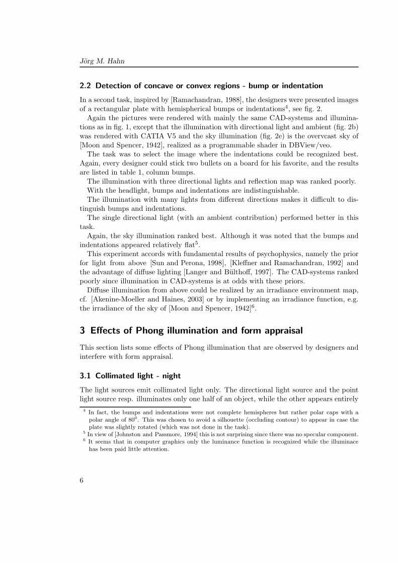
However, this sort of illumination may lead to serious deception of form, cf. [Birn, 2000]or look at fig. 3 for an example from automotive design.
Figure 3: A rim illuminated by ambientlight.Picture rendered in CATIA. The humpseems to vanish below the arrow, where onlyambient light contributes.
Many lights Placing many light sources in the scene is another strategy to overcomedark regions. Often these light sources are located on the side of the observer (frontlights) and move with the camera. This is the default in ICEM Surf.
7
Jorg M. Hahn
This illumination makes it difficult to distinguish bumps and indentations.
Moving lights In an interactive session, where the model is rotated or the observerwalks around, the headlight, or more general, the front lights must move with the camera.
Lights moving with the observer may seem acceptable, if the observer moves horicon-tally. However, with vertical movement or with steeper viewing angle as the observerapproaches, this may look strange to a designer as he does not expect the brightness ofsurface regions to change so dramatically if seen from above. It should also be notedthat moving lights are in conflict with the visual prior that light sources are stationary,cf. [Kersten et al., 1994].
However, the need for moving light may also aid form appraisal. With only onemoving light source the light break moves over the surface giving strong shape hints.Such dynamic illumination is used frequently by modellers for surface inspection.
3.2 Shadows
The first thing apparent to designers is the absence of cast shadows. Designers are oftenpuzzled that light passes through objects without casting a shadow. Without a shadow,the car model seems to float above the ground, gap lines (e.g. around the doors) can notbe evaluated, and undercuts (e.g. of the dashboard) are underestimated and thereforetend to become exaggerated in digital work.
However, the absence of cast shadows is beneficial to headlight. For other lights, theabsence of shadows is visible, while the latter is correct even without shadows.
3.3 Reflections
Reflection maps also show something in areas that are not reached by light. Thereforethey often play an undue role in computer graphics. Designers do not like too strongreflections, they say that the model sometimes is mirrored to death or ask to turn offthe reflections, I want to see the form.
However, reflections can also give valuable shape hints, cf. [Fleming et al., 2004].
3.4 Highlights
Highlights play an important role in shape recognition, and many designers prefer fairglossy materials like metallic car paint to appraise form. They say metallic car paintsemphasize the form.
Glossy materials show stronger gradients of brightness along curvature than mattematerials. The glossy highlights emphasize the ridges and fillets on a surface. Alonga ridge the variation of the normal is greater than in regions with smaller principalcurvatures (cf. e.g. [Koenderink, 1990]) With the normals also the reflected viewing
8
What’s wrong with Phong
directions subtend a larger solid angle. Now, given a distribution of light sources, it ismore likely that the highlight from a light source will happen to lie on the ridge. Andif the highlight is on the ridge, it will be distorted, i.e. elongated in the direction of theridge, cf. [Blake and Bulthoff, 1991], [Blake and Brelstaff, 1988]. Thus ridges becomevisible, and designers can read them as feature lines or character lines.
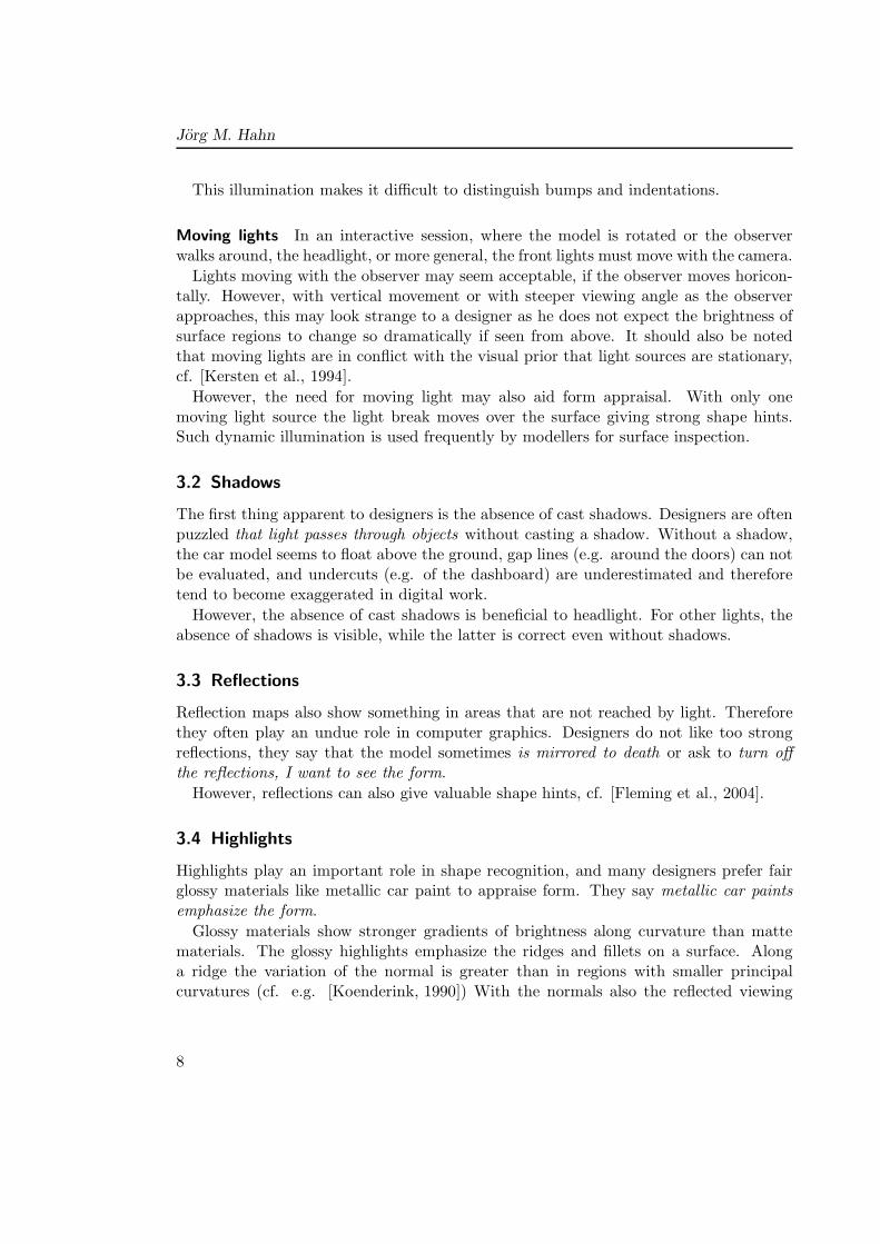
Size of highlight When asked to comment on the appearance of highlights in digitalrenderings, a designer called them too soft and dull.
Figure 4: Sharpest Phong highlight on a carroof.Picture rendered in DBView.
In OpenGL, the shininess exponent of the Phong highlight is restricted to 7 Bit (i.e.mshiny ≤ 127). This causes large highlights. Fig. 4 shows the sharpest Phong highlighton a car roof. In reality, the highlight of the sun on a smooth convex surface can alwaysbe covered by the tip of the small finger at arm length.
The larger a highlight is on a ridge, the softer the shape appears. Crisp highlights areneeded to convey crisp shapes7. To achieve a more realistic sun highlight, the shininessexponent would have to go up to 5-10 000.
On the other hand, the larger highlights compensate for the discrete character (zerowidth) of the Phong light sources, see sec. 3.4, or may somewhat simulate the glare effectof bright highlights in reality.
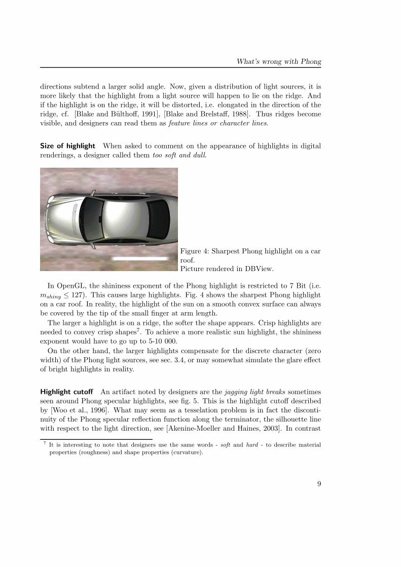
Highlight cutoff An artifact noted by designers are the jagging light breaks sometimesseen around Phong specular highlights, see fig. 5. This is the highlight cutoff describedby [Woo et al., 1996]. What may seem as a tesselation problem is in fact the disconti-nuity of the Phong specular reflection function along the terminator, the silhouette linewith respect to the light direction, see [Akenine-Moeller and Haines, 2003]. In contrast
7 It is interesting to note that designers use the same words - soft and hard - to describe materialproperties (roughness) and shape properties (curvature).
9
Jorg M. Hahn
Figure 5: Highlight cutoff on a windscreen.Picture rendered in ICEM Surf.
to the diffuse reflection component, which continuously goes down to zero at grazing an-gles following Lamberts cosine law, the specular component is independent of the anglebetween surface normal and light direction as long as this angle is acute, and suddenlyvanishes as the angle gets obtuse.
Highlight cutoff may be seen if a light source is nearly opposite to the viewing direction.It does not occur with headlights or (moving) frontlights. Thus it is concealed by poorlighting.
The modified Phong model of [Lewis, 1994] is a simple cure to this flaw.
Highlight cutoff is a nuisance that may appear suddenly in an interactive form ap-praisal session. It is clearly identified as an artefact if jagging is concerned and mayquestion the credibility of digital form appraisal. It may be even more critical, if thetesselation is so fine that the cutoff line is smooth. In that case the cutoff line maybe interpreted as a surface feature, possibly as a kink line, but more likely, the regionbehind the cutoff is seen as a shadow.
Although it is physically unrealistic and doesn’t behave like a shadow if viewed inmotion (it rather is an isophote), a moving terminator may even leverage form appraisal,similar to sec. 3.1.
4 Behaviour of Light and Material
Designers state that adjusting lights and materials is too complicated. Illumination is anenduring task, in particular in an interactive 3D application where the user may walkaround the object and see it from behind. The lighting often needs re-adjustment for anew perspective.
Firstly this needs an expertise that designers do not need in the real world - designershardly ever adjust lights when looking at real objects8. Secondly, it is so complicated,
8 The notable exception is class A surface inspection, where panels with parallel light rods are positioned
10
What’s wrong with Phong
because the lights behave differently to the real world.
4.1 Illumination terminator
A drawback of illumination in CAD-systems is that it is normally not gamma-corrected.I.e. the non-linear transfer function from coding to brightness on the display is not takeninto account, cf. [Poynton, 1998], [Poynton, 2003]. And this effect is visible to designers.
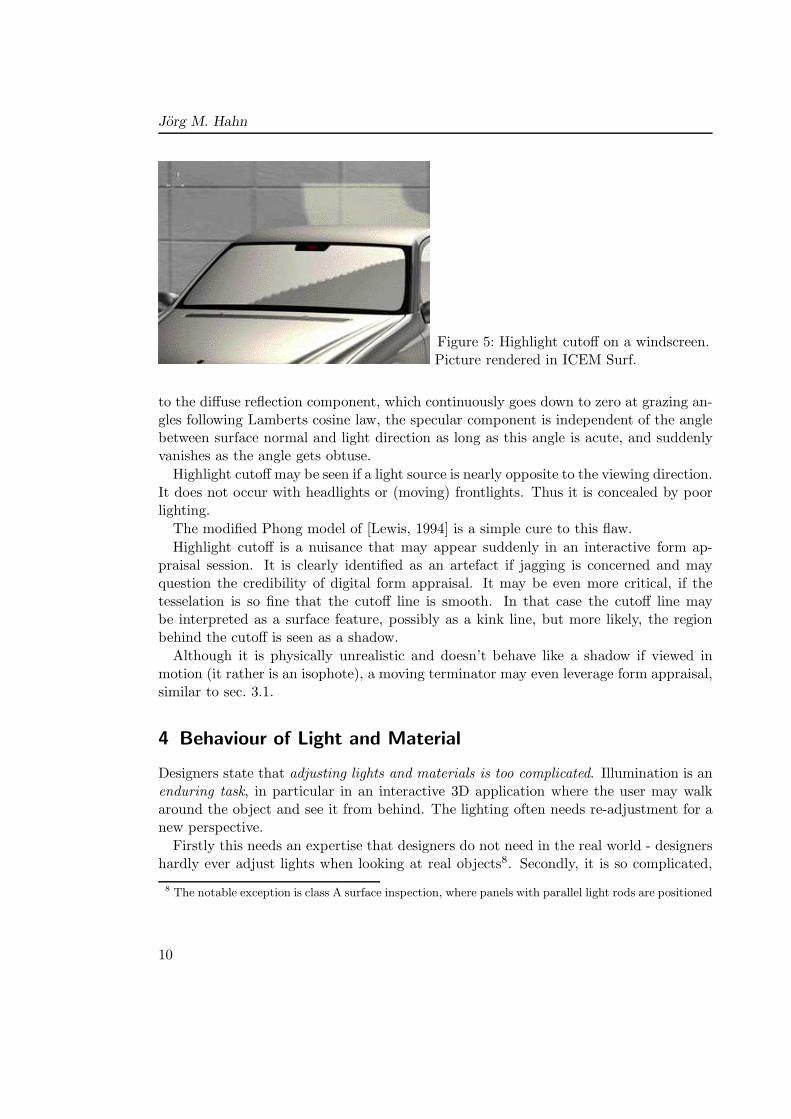
Fig. 6 shows two pictures of a sphere illuminated by a directional light source, calcu-lated without and with gamma correction, resp.
Figure 6: A sphere illuminated by a directional light source.Left without and right with gamma correction. The sphere was assigned an ideal mattewhite material (Lambertian shader). Pictures rendered with Alias AutoStudio.
The two pictures were presented to a group of designers. When asked, which pictureshowed a ball illuminated by a directional light source, most designers named the firstpicture.
However, when asked, which picture showed a ball illuminated by a ”laser beam”, themajority voted for the second picture.
Physically, it is clear that a directional light source represents an ideal laser beam,and should give rise to a hard light break a.k.a. terminator, cf. [Birn, 2000].
Surprisingly, CAD-systems often show soft light breaks. This may look realistic, sincereal life light sources also produce soft light breaks. But the position of the terminator iswrong: The area illuminated by a real light source would extend over 900 (polar angle)while with the ideal light source it is strictly confined to a hemisphere.
Correcting the gamma transfer makes light breaks get harder and look more unreal-istic, i.e. reveals the laser beams. This could give a reason, why gamma correction -although well known - is missing in CAD-systems.
around the model to follow the reflection lines.
11
Jorg M. Hahn
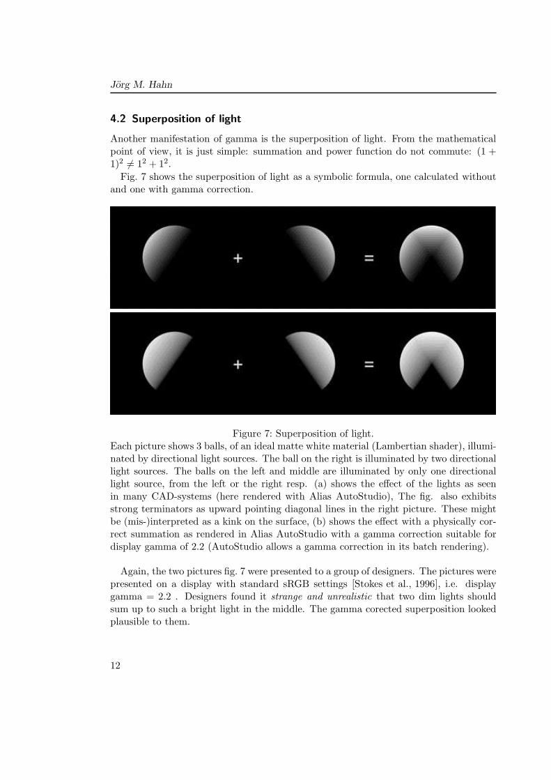
4.2 Superposition of light
Another manifestation of gamma is the superposition of light. From the mathematicalpoint of view, it is just simple: summation and power function do not commute: (1 +1)2 6= 12 + 12.
Fig. 7 shows the superposition of light as a symbolic formula, one calculated withoutand one with gamma correction.
Figure 7: Superposition of light.Each picture shows 3 balls, of an ideal matte white material (Lambertian shader), illumi-nated by directional light sources. The ball on the right is illuminated by two directionallight sources. The balls on the left and middle are illuminated by only one directionallight source, from the left or the right resp. (a) shows the effect of the lights as seenin many CAD-systems (here rendered with Alias AutoStudio), The fig. also exhibitsstrong terminators as upward pointing diagonal lines in the right picture. These mightbe (mis-)interpreted as a kink on the surface, (b) shows the effect with a physically cor-rect summation as rendered in Alias AutoStudio with a gamma correction suitable fordisplay gamma of 2.2 (AutoStudio allows a gamma correction in its batch rendering).
Again, the two pictures fig. 7 were presented to a group of designers. The pictures werepresented on a display with standard sRGB settings [Stokes et al., 1996], i.e. displaygamma = 2.2 . Designers found it strange and unrealistic that two dim lights shouldsum up to such a bright light in the middle. The gamma corected superposition lookedplausible to them.
12
What’s wrong with Phong
In CAD-systems running on ordinary screens9, the superposition of light is too bright.This is one reason that overflows occur so frequently. Loosely speaking, with a displaygamma of roughly 2, CAD-systems compute ”1 + 1 = 4”. Probably these are the onlysystems engineers use nowadays that calculate that way.
The strange behaviour of superposition, the unexpected appearance of bright spots oroverflows, is one reason that makes adjusting light so complicated.
Proper gamma correction would reconcile the situation.
4.3 Coupling of light and material
Another effect that annoys designers who want to adjust light or material parameters,is the coupling of light and material.
Material gloss and intensity of light source One well known effect is that shininess isnot normalized, cf. e.g. [Lewis, 1994]. Modifying the shininess exponent to adjust thesharpness (concentration) of the highlight (i.e. the gloss of the material) also varies theamount of reflected light or the intensity of the light source. If the shininess exponentgets smaller, more light is reflected. For shininess exponent mshiny < 6 more light isreflected than received!
This causes frequent overflows for small shininess exponent and the overflow regionappears flat.
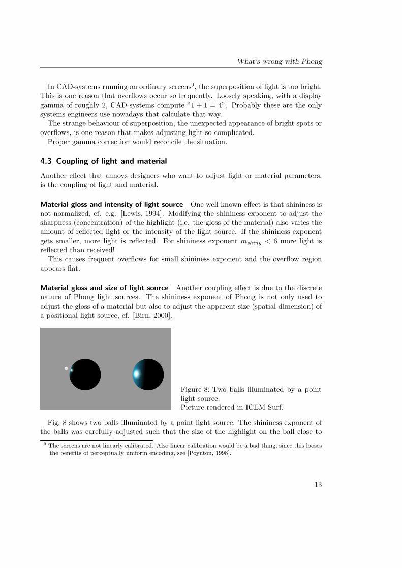
Material gloss and size of light source Another coupling effect is due to the discretenature of Phong light sources. The shininess exponent of Phong is not only used toadjust the gloss of a material but also to adjust the apparent size (spatial dimension) ofa positional light source, cf. [Birn, 2000].
Figure 8: Two balls illuminated by a pointlight source.Picture rendered in ICEM Surf.
Fig. 8 shows two balls illuminated by a point light source. The shininess exponent ofthe balls was carefully adjusted such that the size of the highlight on the ball close to
9 The screens are not linearly calibrated. Also linear calibration would be a bad thing, since this loosesthe benefits of perceptually uniform encoding, see [Poynton, 1998].
13
Jorg M. Hahn
the light source matches the apparent size of the light source as indicated by the lightsymbol. The highlight on the right ball is bigger than on the left, while in reality, anextended light source would cause a highlight on the distant ball that is smaller thanon the nearby ball10. Within the Phong illumination model, this appearance could onlybe achieved, if the distant ball was assigned a different shininess exponent, i.e. anothermaterial, or with per object lighting.
Thus a material parameter (gloss or size of highlight) accounts for properties of thelight source (intensity and size).
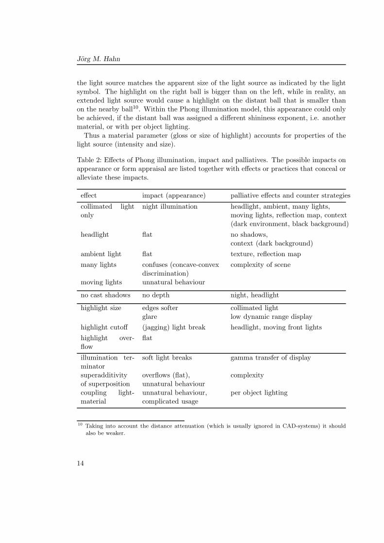
Table 2: Effects of Phong illumination, impact and palliatives. The possible impacts onappearance or form appraisal are listed together with effects or practices that conceal oralleviate these impacts.
effect impact (appearance) palliative effects and counter strategies
collimated lightonly
night illumination headlight, ambient, many lights,moving lights, reflection map, context(dark environment, black background)
headlight flat no shadows,context (dark background)
ambient light flat texture, reflection map
many lights confuses (concave-convexdiscrimination)
complexity of scene
moving lights unnatural behaviour
no cast shadows no depth night, headlight
highlight size edges softer collimated lightglare low dynamic range display
highlight cutoff (jagging) light break headlight, moving front lights
highlight over-flow
flat
illumination ter-minator
soft light breaks gamma transfer of display
superadditivityof superposition
overflows (flat),unnatural behaviour
complexity
coupling light-material
unnatural behaviour,complicated usage
per object lighting
10 Taking into account the distance attenuation (which is usually ignored in CAD-systems) it shouldalso be weaker.
14
What’s wrong with Phong
5 Summary and Conclusion
The Phong illumination model has one main deficiency and several faults, that are listedin table 2. There is no diffuse light. It is the diffuse light of sky that makes the differencebetween day and night, not that the night was just darker. Thus, the illumination inCAD-systems is in essence the illumination of the night.
Some effects make objects appear flat, others exhibit light breaks that are not physi-cally plausible and might be taken for a kink. Together these may give the impression ofa cardboard box, as a designer had put it. Thus Phong illumination is not just a limitedsimulation of reality, it has a bias in a particular direction.
Other effects are in conflict with real life experience or are at odds with priors of visualperception. And this presumably has an impact on form appraisal.
Some effects are concealed by others or are alleviated by common practices of digitalrendering. Probably these palliatives have prevented faults from being fixed.
It seems that Phong illumination is an unintentionally balanced model with well knownfaults, but where luckily one flaw conceals another one. Thus curing one flaw only, maymake it worse.
Nevertheless it is a question, why such a poor illumination is still alive in CAD-systems. Is it because perception can well adapt to poor lighting11, or is it that shadingis a weak cue, in particular if the user can interact with the digital model and see it inmotion, or is it just its simplicity?
It is a challenge for research to define an illumination model that aids visual perceptionand is still simple enough to enter CAD-systems.
References
[Ope, 1999] (1999). OpenGL Specification. OpenGL, 1.2.1 edition.
[Akenine-Moeller and Haines, 2003] Akenine-Moeller, T. and Haines, E. (2003). Real-Time Rendering. A.K. Peters Ltd., http://www.realtimerendering.com, 2nd editionedition.
[Birn, 2000] Birn, J. (2000). Digital Lighting & Rendering. New Riders Publishing,http://www.3drender.com/.
[Blake and Brelstaff, 1988] Blake, A. and Brelstaff, G. (1988). Geometry from specular-ities. In Proc. Int. Conf. Comput. Vision (ICCV), pages 394–403.
[Blake and Bulthoff, 1991] Blake, A. and Bulthoff, H. (1991). Shape from specularitis:computation and psychophysics. Philosophical Trans. of the Royal Society of London- Series B: Biological Sciences, 331:237–252.
11 or as a modeller has put it: the screen lies but you can learn.
15
Jorg M. Hahn
[Ferwerda et al., 2004] Ferwerda, J. A., Westin, S. H., Smith, R. C., and Pawlicki, R.(2004). Effects of rendering on shape perception in automobile design. In Symposiumon applied Perception in graphics and visualization, pages 107–114. ACM.
[Fleming et al., 2004] Fleming, R. W., Torralba, A., and Adelson, E. H. (2004). Specularreflections and the perception of shape. Journal of Vision, 4:798–820.
[Hunter and Fuqua, 1997] Hunter, F. and Fuqua, P. (1997). Light Science & Magic, AnIntroduction to Photographic Lighting. Focal Press, Boston, 2nd ed. edition.
[Johnston and Curran, 1996] Johnston, A. and Curran, W. (1996). Investigating shapefrom shading illusions using solid objects. Vision Research, 36:2827–2835.
[Johnston and Passmore, 1994] Johnston, A. and Passmore, P. (1994). Shape from shad-ing ı, surface curvature and orientation. Perception, 23(2):169–189.
[Kersten et al., 1994] Kersten, D., Mamassian, P., and Knill, D. C. (1994). Movingcast shadows and the perception of relative depth. Technical Report 006, MPI-kyb,ftp://ftp.kyb.tuebingen.mpg.de/pub/mpi-memos/TR-006.ps.Z.
[Kleffner and Ramachandran, 1992] Kleffner, D. and Ramachandran, V. (1992). On theperception of shape from shading. Percept Psychophys., 52(1):18–36.
[Koenderink, 1990] Koenderink, J. J. (1990). Solid Shape. MIT Press, Cambridge, Mass.
[Koenderink and van Doorn, 2003] Koenderink, J. J. and van Doorn, A. J. (2003).Shape and shading. In Chalupa, L. and J.S.Werner, editors, The visual neurosciences,pages 1090–1105. MIT Press, Cambridge.
[Langer and Bulthoff, 1997] Langer, S. and Bulthoff, H. (1997). Qualitative shape fromshading: Cloudy days and sunny days. Investigative Ophthalmology & Visual Science,38.
[Lewis, 1994] Lewis, R. R. (1994). Making shaders more physically plausible. ComputerGraphics Forum, UK, 13(2):109–20.
[Moon and Spencer, 1942] Moon, P. and Spencer, D. (1942). Illumination from a non-uniform sky. Illum. Eng, 37:707 – 726.
[Parker et al., 1992] Parker, Christou, and Cunnings (1992). The analysis of 3dshape:psychophysical principles and neural mechanisms. In Humphreys, G., editor,Understanding Vision, pages 143–179. Blackwell, Oxford.
[Phong, 1975] Phong, B. T. (1975). Illumination for computer generated pictures. Com-munications of the ACM, 18(6):pp 311–317.
16
What’s wrong with Phong
[Poynton, 1998] Poynton, C. (1998). The rehabilitation of gamma. In Rogowitz, B. E.and Pappas, T. N., editors, Proceedings of SPIE/IS&T Conference in San Jose, Calif.,Jan. 26 - 30, 1998, number 3299 in Proceedings of SPIE, pages 232–249. SPIE.
[Poynton, 2003] Poynton, C. (2003). Digital Video and HDTV. Morgan Kaufmann, SanFrancisco.
[Ramachandran, 1988] Ramachandran, V. S. (1988). Perception of shape from shading.Nature, 331:163 – 166.
[Rodger and Browse, 2000] Rodger, J. and Browse, R. (2000). Choosing rendering pa-rameters for effective communication of 3d shape. IEEE Computer Graphics andApplications, pages 20–28.
[Stokes et al., 1996] Stokes, M., Anderson, M., and Motta, S. C. R.(1996). A Standard Default Color Space for the Internet - sRGB.http://www.w3.org/Graphics/Color/sRGB.
[Sun and Perona, 1998] Sun, J. and Perona, P. (1998). Where is the sun? natureneuroscience, 1:183–184.
[Ward, 1994] Ward, G. J. (1994). The radiance lighting simulation and rendering system.In Computer Graphics (Proceedings of ’94 SIGGRAPH conference). SIGGRAPH.
[Ward, 2001] Ward, G. J. (2001). Local illumination is all that matters forgraphics realism. SIGGRAPH and Eurographics Campfire, Snowbird Utah.http://isg.cs.tcd.ie/campfire/gregward.html.
[Ward, 2003] Ward, G. J. (2003). Real numbers real images. Eurographics.
[Woo et al., 1996] Woo, A., Pearce, A., and Ouellette, M. (1996). It’s really not arendering bug, you see ... IEEE CG&A, 16(5).
17


![[XLS] · Web viewIntroduction PV basics PV for designers Design of the building envelope Shading systems Rainscreen systems Stick-system curtain walls Unitised curtain walls Double-skin](https://img.pdfslide.net/doc/110x75/5bcbeef309d3f2e1348cf65e/xls-web-viewintroduction-pv-basics-pv-for-designers-design-of-the-building.jpg)