Embed Size (px)
Citation preview

Wheel Casting

Introduction
• IR mfgs. Cast Steel Bogies & wheels
– CASNUB bogies at CLW
– Cast wheels for Wagons & Coaches
• Rail Wheel Factory (RWF) at Bangalore
– Capacity 1.2 lac/ annum – prodn. 2lac/annum!
– TOT from Griffin of USA
• Rail Wheel plant (RWP) at Bela, Patna
– Capacity 1.0 lac/ anum – new set up
• Copy of RWF
• Demand of wheel > 3lacs/ annum 29/06/2015 2

Cast Steel Wheels
• Special Parabolic profile
• Very low P & S content
• Fine equiaxed grained structure
• High yield to tensile ratio resulting from
– Specially designed heat treatment process
• Round shaped non-metallic inclusions
• IR Specification R – 19 / 1993 Pt-III
– Both for Carriage & Wagon Wheels
29/06/2015 3

29/06/2015 4
Cast Steel Wheels
• Metallurgically forging route better than
casting
• Special technique of controlled pressure
casting
– Equivalent to forging route, even better
• Cross dendritic structure
– Barrier to dislocation movement
• Stipulated Mech. properties are well met

29/06/2015 5
Cast Vs. Forged Wheels
• High rate of production with uniform Quality
• Eliminates machining, any plate design
• Internal defect position is known – So, very easy to ensure soundness
• Cleanliness by refining of steel in EAF
• Unique deoxidation ensures globulized alumina
– These helps in achieving K1C value
• High K1C value
– Resistance against catastrophic failure in service

Chemistry of Cast Wheel
Elements Wagon wheels (BOXN) Coaching Wheels
Carbon 0.57% to 0.67% 0.47% to 0.57%
Mn 0.6% to 0.8% 0.6% to 0.8%
Si 0.15% to 0.70% 0.15% to 0.70%
S 0.03% Max 0.03% Max
P 0.03% Max 0.03% Max
Cr 0.15% Max 0.15% Max
Mo 0.06% Max 0.06% Max
Ni 0.25% Max 0.25% Max
Cr + Mo +
Ni
0.40 Max 0.40 Max
29/06/2015 6

CASTING & HEAT TREATMENT
29/06/2015 7

Liq. Steel from EAF
• Mainly Railway scraps melted in EAF
• Chemistry adjusted to reqd. spec.
• Temperature raised to required level
– 16800C – 16900C for coaching wheel
– 16900C – 17000C for wagon wheel (BOXN)
• Tapped in preheated ladle
• Nominal capacity 20 MT
29/06/2015 8

Tapping from EAF

Mould Blank

Cope

Drag

29/06/2015 13
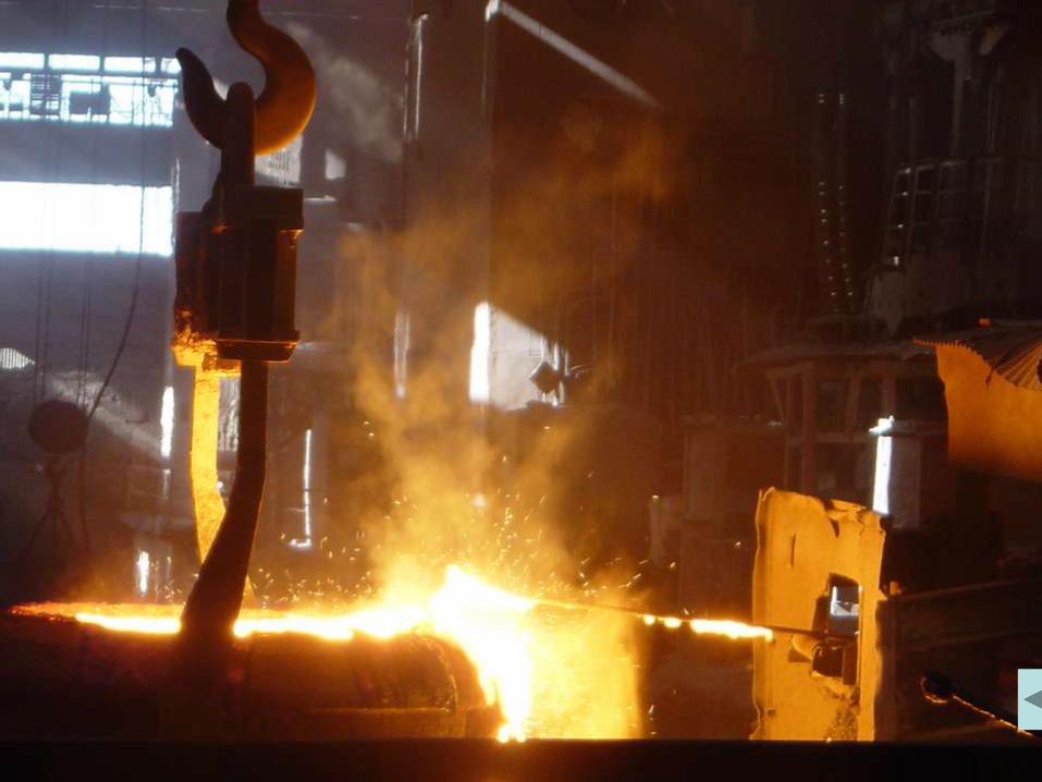
Wheel Casting
• Major slag is removed from the top of ladle
• Ladle placed in ‘JOHN MOHR’ Pit
• Al. star thrust into as final deoxidiser
• Sample taken for Chemical Analysis & H2
• Top cover with Silimenite tube sits on top
• Graphite Mould sits on the top of tube
• Pit pressurised by air to lift the liq. Metal
• Liq. Metal flow to the mould to fill cavity

29/06/2015 14
Wheel Casting Contd…
• Plunger brought down to seal the gating
• Mould placed on conveyor, next one in
• Stripping after pre-determined time
– to take away the Risers along with top
• Wheels placed on conveyor to tunnel
• Moulds go back for cleaning and recycling
• Sprue Wash, Stamping & Hub Cutting

Slag Off Station

Placing at John Mohr Pit

Cope & Drag Assembly

Mould Cavity Filling

Wheel Parting from Mould

Hot Wheel Kiln

Sprue Washing/Grinding

Hub Cutting

Heat Treatment
• Placed to Moving Bed Normalising
Furnace • 7000C→10000C→9600C→9600C→9600C
• Followed by Rim Quenching
• Water jet on rim for 4-5 min.
• Tempering in Draw fce. at 5000C for 2hrs
• Hub Quenching in 3 stages, 40 sec each
• Air cooling to RT
29/06/2015 23

29/06/2015 24
Wheel Inspection
• Apex grinding
• Shot blasting to clean
• Hardness Testing
• Visual Inspection in normal light
• Magnaflux Test for surface & sub-surface
under UV light, mainly for cracks
• Wheels with removable defect sent for defect
removal through grinding & rechecking

Magnetic Particle Testing

29/06/2015 26
Wheel Inspection Contd…
• Automated Multi probe UT in Sprue area
• Final Hub boring
• Final shot blasting
• Warpage checking
• Final Dimensional checking
• Closure test, Mech. test & BHN mapping
• 1 in 500 for Coach wheels
– 1 in 1000 for BOXN wheels
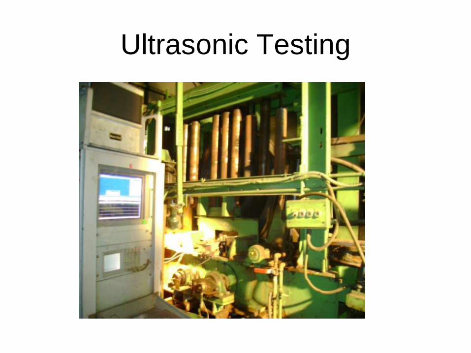
Ultrasonic Testing

Wheel Routing

Defect Codification
• Codes for some common defects
10 - Cracks
12 - Ceramic, Metal refractory
13 - Slag
15 - Pinholes
16 - Ultrasonic
32 - Gouged hub bore
35 - Gouged riser
46 – Pock holes
51 - Lap
62 - Mould inclusions

10 - Crack

12 – Metal Refractory

13 – Slag Inclusion

15 - Pinhole

51 - Lap

32 – Gouged Bore

47 – Pocker Holes

62 – Mould inclusion

Defect Removal

29/06/2015 39
RWF & Wheel Production.
• Producing both BOXN & Carriage wheels
• Production target this year is 2 lacs
– Against rated capacity of 1.2 lacs
• Continuous three shift operation
• Looking forward for Loco wheel production
• Axle forging from bloom a parallel activity
• Final product: Wheel sets & loose wheels
• Total production connected by LAN

Refractory Management

Prologue
• IR uses different types of furnaces
– High temp EAF & Ladle for cast steel
– High temp Cupola for cast iron
– Medium Temp HT furnaces
– Low temp Tempering, Stress Relieving furnace
etc
• All these furnaces need different refractories
• In this section, EAF, Ladle, HT & Draw
furnace refractories are covered
12/27/2014 41
Introduction
• Refractory is the material which can retain
its strength at high temperature
• Both Graphite & Alumina are refractory,
but
– Thermal conductivity is widely different
– Those with low TC normally called refractory
• Used to conserve heat & protect shell
• Different type of refractories for different
furnace and different sections of a furnace 12/27/2014 42

43
Chararecteristics of Refractory
• For furnace application, materials that – Withstand high temperatures and sudden
changes
– Withstand action of molten slag, glass, hot gases etc
– Withstand load at service conditions
– Withstand abrasive forces
– Conserve heat
– Have low coefficient of thermal expansion
– Will not contaminate the load
are called refractories
12/27/2014

EAF REFRACTORIES
12/27/2014 44

Electric Arc Furnace
• Most versatile equipment for production
Steel
• With high power rating furnaces, the load
on refractories has gone up considerably
• Some developments reduced consumption
– Water cooled panel
• 85% of roof and 70% of side walls water cooled
– LF, EBT, DC furnace etc.
• In IR, only water cooled panels are used
12/27/2014 45

Structure of EAF
• A typical EAF has following basic areas
– Circular shallow bath with a dish shaped bottom
– Cylindrical side walls with slag door
– Dome shaped roof with circular openings for
electrodes, fume extraction etc.
– Tap hole
• Different service condition of various areas
– Requires different types of refractory materials
12/27/2014 46

Roof of EAF
• One of the most affected portion subjected to
all kind of stresses; thermal, chemical &
mechanical
– very high temperature often exceeding 1700°C
– Corrosive action of slag and metal oxides
• Specially iron oxide fumes which is deleterious
– mechanical stresses. Due to complicated design
• Spalling due to temp fluctuation
• Formation of low melting compounds
12/27/2014 47

Roof of EAF
• The problem has been tackled in two ways
– by improving the quality of refractories
– by changes in the design of laying
• Conventionally Silica Bricks
• Can not meet present day requirements
– High alumina materials (up to 95% Al2O3)
– castables with Cr oxide or pre-fabricated shapes
– Water cooled roofs
12/27/2014 48

Side wall of EAF
• Subjected to – Severe thermal shock
– corrosive slag action
– Mechanical abuse during charging etc.
• 3 different zones, Slag, Roof drip & Hot spot – Hot spots zones - most severe condition
• Exposed to very high arc temp as well as slag
• Reflected bath heat
• Mag-carb bricks with 10-15% carbon with water cooled panel
12/27/2014 49

Hearth of EAF
• Hearth or bottom - a receptacle of liquid metal and slag
• Has to withstand very arduous service condition – High temperature
– Thermal stress due to fluctuation in temp. before and after tapping
– Slag and metal corrosion
– Mechanical abuse during charging
– High structural stresses during tapping at maxm. tilt
12/27/2014 50

Hearth of EAF
• Divided into two sections
– Sub-hearth with few layers of high fired magnesite bricks along with a fire bricks lining against the shell
– Working hearth or bottom made by ramming dolomite or magnesite, known as DRM • Provides a monolithic, joint free surface
• Thickness around 250-300 mm
• Life 5000 - 10000 heats depends upon size of furnace and operating parameters.
12/27/2014 51

Hearth of EAF
• DRM with little water & MgSO4
• Ramming or vibration with a vibrator
• After around 50 heats, top layer scraped out
• Fresh layer of DRM rammed to replenish
• Heating up of cold furnace – Light wood & charcoal lit up to drive out water
– Light scrap/boring about 500kg and arcing to heat
– Normal charging & arcing at low rate
– Holding at 12000C for 30 min
– Slow heating to desired temp.
12/27/2014 52

Tap Hole & Launder
• High Alumina brick joined by Alumina mortar
• Top surface repaired by WRM occasionally
• Tap hole plug to block tap hole – A mound with fireclay and graphite in water
– Tap hole packed
– Top surface with fireclay paste
– During tapping, the mass speared open
– Sometimes early opening of hole and metal flowing
– Higher Graphite, easier to open
12/27/2014 53

LADLE REFRACTORIES
12/27/2014 54

Ladle & Refractory
• Ladle is a bucket shaped container, flat bottom – Refractory lined round steel container
– Carrying liq. Metal from furnace to pouring station
• In IR different refractories for ladle lining – High alumina (70% min) brick
– High Alumina mortar
– High heat duty safety layer
– WRM
– DRM
12/27/2014 55

Ladle Preparation
• 1st layer – High heat duty fireclay bricks to IS 8
• Then bottom layer of High Alumina brick
• Gaps packed with DRM, sealed with mortar
• Vertical wall built up with a gap, mortar joint
• Gap packed with DRM, burnt refractory etc.
• Built up to rim, keeping lip opening
• Finished with WRM paste
12/27/2014 56

Ladle Preheating Cycle
• Before use, a definite preheat cycle to follow
– Air dry for 24 hours
– Heat at a rate of 500C per hr. till 3500C
– Soak for 4 hrs.
– Heat at a rate of 500C per hr. till 12000C
– Soak for 4 hrs.
– Lower at 9000C and hold till called for tapping
• A well prepared ladle lasts around 24 heats
12/27/2014 57

Synchronising Tapping Cycle
• Tap to tap time of a fce. ideally 2½ hrs.
• Two fce. should run simultaneously – At a phase lag of 1¼ hrs
• Pouring time 1hr, manipulation 15 mins.
• When ladle is empty, next fce. ready for tap
• If not possible for any disruption – Drain the ladle, clean by oxygen blowing
– put at ladle pre-heater and maintain 9000C
• Never allow the temp. to come below 7500C
12/27/2014 58

NORMALISING & DRAW
FURNACE
12/27/2014 59
NF and DF Refractory
• NF is Rotating hearth type fce.
• Different zones temp. from 5000C to 10000C
• At low temp, 45% alumina brick
• At higher temp, 55% alumina brick
• Slow heat to 3500C, soak 3 hrs, raise to 9xx000C
• Once lighted, should not be put off!
• At bottom and pedestal, 55% alumina mortar
• DF is walking hook type fce. at 5000C
• Lined with 45% alumina brick
12/27/2014 60

TESTING OF REFRACTORIES
12/27/2014 61

Common Test Parameters
• Chemical composition – %age of Alumina, Magnesia, Silica, C, Cr-oxide
etc. as the case may be
– %age of Fe as FeO
– %age of Li, Na, K
• Bulk density – Amount of refractory material within a volume
(kg/m3)
– High bulk density means high volume stability, heat capacity and resistance
12/27/2014 62

Common Test Parameters
• Porosity
– Volume of open pores as % of total refractory
volume
– Low porosity = less penetration of molten material
• Cold crushing strength
– Resistance of refractory to crushing
• Permanent Linear Change(PLC)
– Permanent change in dimension after heating to
working temperature and cooling down
12/27/2014 63
Common Test Parameters
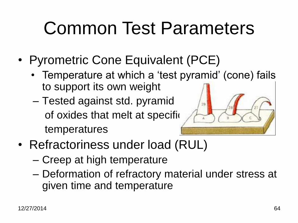
• Pyrometric Cone Equivalent (PCE) • Temperature at which a ‘test pyramid’ (cone) fails
to support its own weight
– Tested against std. pyramid
of oxides that melt at specific
temperatures
• Refractoriness under load (RUL) – Creep at high temperature
– Deformation of refractory material under stress at given time and temperature
12/27/2014 64

Electric Arc Furnace Operation

Introduction
• Steel is primarily produced from pig iron
• Pig iron is produced from various iron ores
– Oxides, Carbonates, Sulphides etc. of iron
– Mixed with coke (reducing agent & Fuel)
– Charged in Blast furnace
– Reduced to iron in liq. form
– Contains large amount of other elements like
Si, Mn, S, P, etc.
29/06/2015 66

Introduction
• Treated in various converters like O/H,
Bessemer, L/D, etc to controlled chemistry
– End product is steel – normally mild steel
– Rolled to plate, sheet, bar, beams, channels
etc. for different commercial use
• Known as Primary Steel Making
• Normally Heavy Industry like TISCO, SAIL
• One more process is DRI
29/06/2015 67

Secondary Steel Making
• For specific composition (Low alloy, High
alloy & sophisticated) steels
• Mild Steel scrap as Raw material
• Melting in Electric arc furnace (EAF)
– Different treatment & alloy addition to achieve
desired chemistry
– Tapped in ladle
– Cast to shape or Intermediates
– Further rolled or forged to shape 29/06/2015 68

Secondary Steel Making & IR
• Mfg. of Cast Steel Bogies & wheels
• CASNUB bogies at CLW
• Demand of wheel > 3lacs/ anum
– Rail Wheel Factory (RWF) at Bangalore
• Capacity 1.2 lac/ anum – prodn. 2lac/anum!
• TOT from Griffin of USA
– Rail Wheel plant (RWP) at Bela, Patna
• Capacity 1.0 lac/ anum – new set up
• Copy of RWF
29/06/2015 69

Cast Steel Wheels
• Special Parabolic profile
• Very low P & S content
• Fine equiaxed grained structure
• High yield to tensile ratio resulting from
– Specially designed heat treatment process
• Round shaped non-metallic inclusions
• IR Specification R – 19 / 1993 Pt-III
– Both for Carriage & Wagon Wheels
29/06/2015 70

EAF OPERATION
29/06/2015 71

Furnace Charge
• Graded Steel Scrap with low S & P
– Mostly from Rly. source
• Light scrap – 15 %
• Medium scrap – 35 %
• Heavy scrap – 60 %
• Flux
– Fresh Lime with 90% CaO Min.
• Carburising agent
– Graphite or Petroleum Coke with low S 29/06/2015 72
Charging Quantity & Sequence
• For about 20MT yield
– 22MT Scrap, 200Kg Coke & 1200Kg lime
• Pet coke and 80% of total lime to be
charged at the bottom
• Then light scrap
• Heavy scrap and foundry returns
• Light boring & turning
29/06/2015 73

Operation Sequence
• Lifting of Electrodes
• Opening of hood
• Charging of RM
• Closing the hood
• Lowering of Electrodes
• Start Arcing
29/06/2015 74

Operation Sequence
• Primary Melting through arcing
• Scrap cutting by blowing oxygen
• 1st sample around 15400C with 90% melt
• O2 lancing→2nd sample→Deslag→16200C
• Carbon blocking → RSM → Rabling
• 3rd sample→ Adjustment→ check samples
• Preheated ladle→ Alloy addition
• Melt temp. to17000C → Tapping to Ladle 29/06/2015 75

Operation Sequence
• Slag removal from top
• Taking to JMP
• Al. star addition
• Covering JMP & tube insertion
• Placing of Graphite Mould
• Pressure pouring
• Cope parting & wheel separation
29/06/2015 76

Metallurgical Aspects
• Initial arcing & scrap cutting
– 90% of scrap in molten pool
– Gen Chemistry; C>0.80%
• O2 lancing or ‘C Boiling’
– Bath mixing
– Removal of Hydrogen & Nitrogen
– C reduction
– Dephosphorisation
29/06/2015 77

Phosphorus Removal
• Conditions for dephosphorisation
– Low temperature
– Viscous slag
– Oxidizing condition
– High Basicity (more than 2.5)
• All conditions are met at this stage
• P forms P2O5 and goes out as gas
• C also forms oxides and move out
29/06/2015 78

Metallurgical Aspects
• 2nd sample to ensure C & P level
• Raising bath temperature
• C continues to loose due to dissolved O2
• Add Mn to stop loss; Carbon blocking
– Mn is stronger deoxidiser
• Al → Si → Mn → C
• Slag off and add fresh lime as RSM
– 200kg lime, 50kg graphite and 20kg FeSi
29/06/2015 79

Sulphur Removal
• Large reduction not practical in EAF
– Low S scrap, weeding axle box, rubber etc.
• Conditions for desulpherisation
– Reducing atmosphere
– High basicity preferably > 2.00
– High fluidity of slag.
– Intimate contact between slag & metal
– High temperature of the bath(preferably >
16500C)
29/06/2015 80

Sulphur Removal
• Addition of RSM at high temp.
– S removal conditions are met
• Sometimes little Fluospar addition
– Fluidity increases
– Restrictive, as corrosive to lining!
• FeSi , strong deoxidiser but restrictive
• Rabling to get fresh interface
• Formation of CaS & going to slag
29/06/2015 81

Final adjustments
• 3rd sample should ensure
– S & P within range
– C around 0.5%
• If not, charge Graphite powder
• Raise temp. to 17000C, take 2 samples
consecutively, bring preheated ladle
• Add calculated amt.(based on analysis) of
FeSi, FeMn & Graphite in the ladle,Tap
29/06/2015 82
29/06/2015 83
Tapping or Pouring
• Final deoxidation should be in the ladle.
• Temp of pouring depends on the Carbon & other alloying elements in the steel.
• The size and geometry of casting also determines the temp of pouring.
• Pouring temp should be optimised in the lower side.
• Speed of pouring should be optimised on the higher side.

29/06/2015 84
Power Consumption
• Ideal consumption of power
– 462 KWH/MT (Ref. MSTS)
• Normally it should not exceed more
than 20% of the ideal Power.
• Practical power consumption is 650-700
KWH/MT for making medium carbon steel

29/06/2015 85
Optmising Power Consumption
• Top be loaded with turning & boring
• Will facilitate easy bore-in stage of electrodes
• Excess heavy scrap should not be charged at the bottom.
• This may cause damage to the bottom as well as will take more time to lift the material in melt down stage.
29/06/2015 86
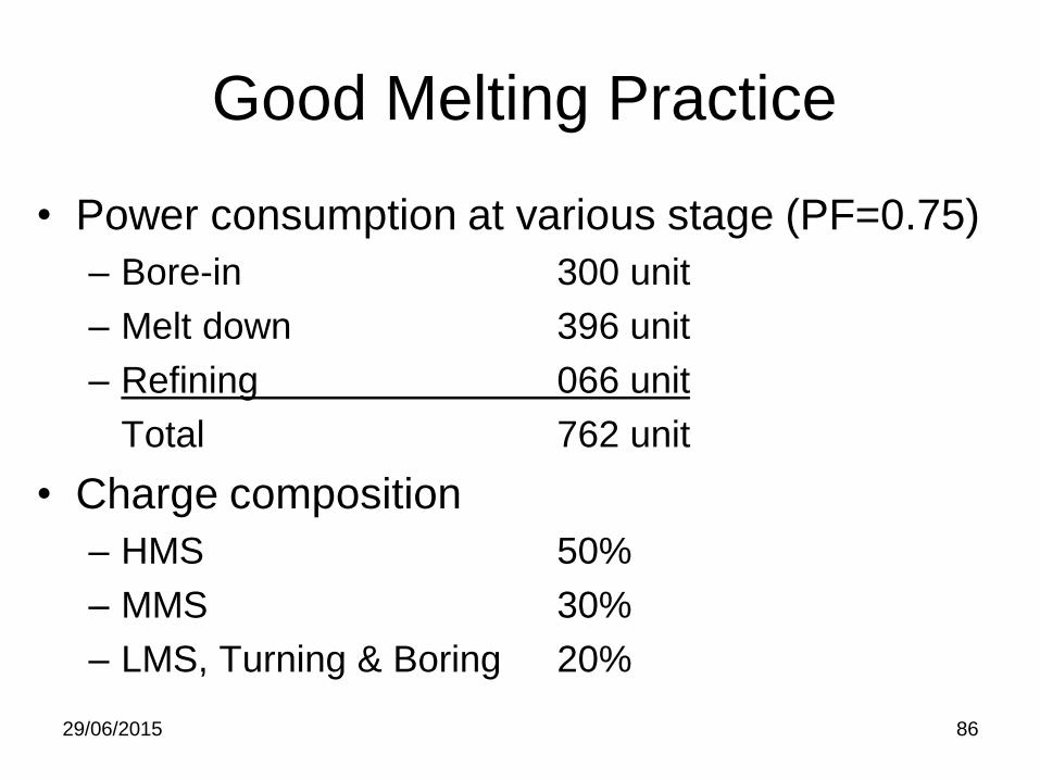
Good Melting Practice
• Power consumption at various stage (PF=0.75)
– Bore-in 300 unit
– Melt down 396 unit
– Refining 066 unit
Total 762 unit
• Charge composition
– HMS 50%
– MMS 30%
– LMS, Turning & Boring 20%

29/06/2015 87
Good Melting Practice
• Avoid over heating of furnace
• Maintain ladle at > 9000C
• Specific pre-heating cycle of ladle
• Correct basicity of slag
• Pre-heated of Scrap & Ferro Alloys
• At least 20 point carbon boil is essential
• Clean steel can be produced in clean and healthy furnace