Embed Size (px)
Citation preview
Number 4, Volume IX, December 2014
Kállai: Wheel Suspension of Fortmula Student 58
WHEEL SUSPENSION OF FORMULA STUDENT
Tibor Kállai1
Annotation: The article deals with wheel suspension of formula student. A proposal follows the rules of SAE International. SAE International is an organizer of Formula Student/SAE competition. Races of formula student are organized all over the world. This competition is becoming very popular in Central Europe and VŠB - TU Ostrava would like to join this competition in the next year. This article was created during the development of the first generation of Formula Student at VŠB-TU Ostrava.
Keywords: Formula Student, wheel suspension, Inventor
INTRODUCTION
The article describes the Summary of the design suspension of the vehicle. The application shall be follows the applicable rules of the organization SAE International. It is the organizer of the competition Formula Student / SAE and organizes all over the world races student formula. We can say, that the students are asked to design and build functional prototype vehicles of formula type. Is driven by a motorcycle engine with a maximum displacement of 610 cm3. The vehicle, built by students, is classified in the race for the riding characteristics in dynamic disciplines. And in static disciplines in the design and marketing plan.
The wheel suspension is an integral part of every vehicle. Construction of wheel suspension connects wheel and frame. The purpose of the wheel suspension is to eliminate undesirable wheel move and enable wheel move versus the frame.
A dependent wheel suspension of vehicle is created of two wheels which are connected by axle bracket and together create solid unit. Contrary the independent wheel suspension is characterized by independent wheel connection. This design enable weight reduction of unsprang vehicle parts.
For student formula the trapezoidal wheel suspension has been used. A pitman of wheel is situated between handles. Suspension and damping is realized by associated suspension/dumping unit. These units are situated nearby each wheel.
1 Ing. Tibor Kállai. VŠB – Technical University of Ostrava, Faculty of Mechanical Engineering, Institute of Transport, 17. Listopadu 15/2172, 708 33 Ostrava-Poruba, Tel: 605 078 904, E-mail: [email protected]
Number 4, Volume IX, December 2014
Kállai: Wheel Suspension of Fortmula Student 59
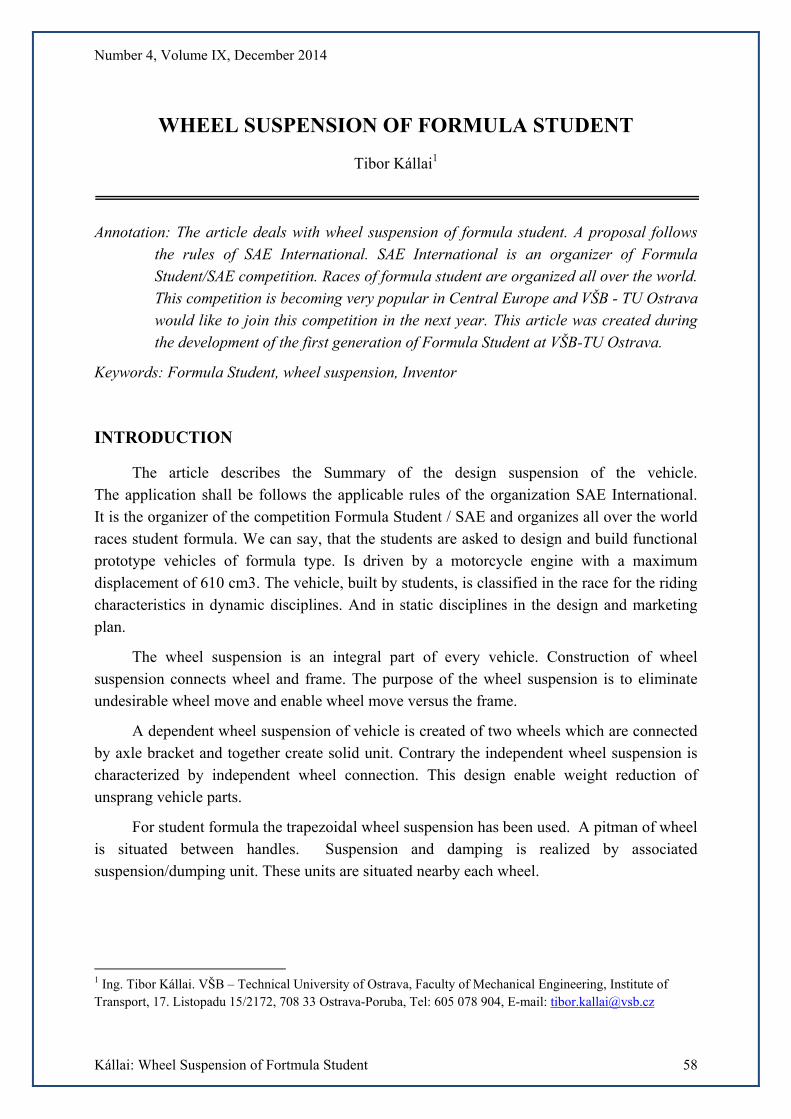
Source: Author
Fig. 1 - Design of students vehicle
1. A DRAFT OF FRONT WHEEL SUSPENSION 1.1 Kinematic arrangement of front wheel suspension
A draft of front wheel suspension we can divide into several steps. First step is a draft of suspension kinematic including optimization of kinematic quantity. The next step is determination of reference point on a frame. This point is situated in a front side of a frame. The point is important for handles location. Designed location point is necessary to optimize on a base of process of suspension kinematic characterization.
1.2 Measurement of process of kinematic characterization of wheel suspension and optimization
Optimization of selected quantity is realized experimentally. During springing of wheel suspension following quantity are measured:
• Change of wheel track
• Change of wheel camber
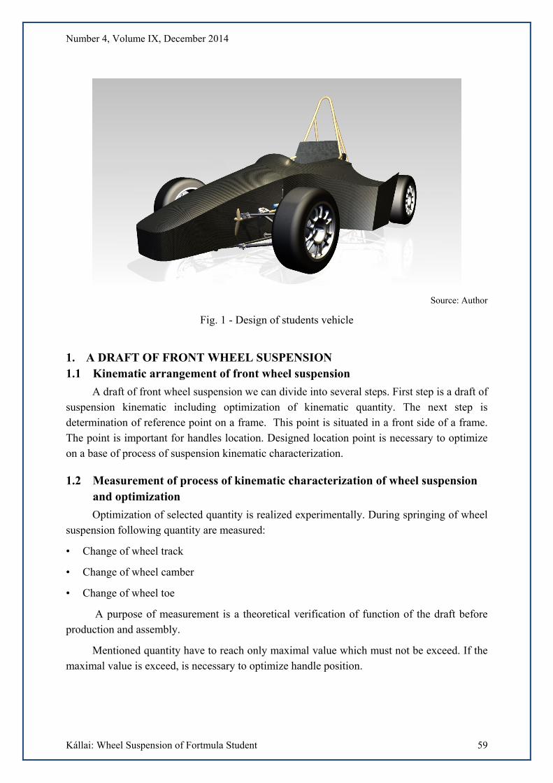
• Change of wheel toe
A purpose of measurement is a theoretical verification of function of the draft before production and assembly.
Mentioned quantity have to reach only maximal value which must not be exceed. If the maximal value is exceed, is necessary to optimize handle position.
Number 4, Volume IX, December 2014
Kállai: Wheel Suspension of Fortmula Student 60
Source: T. Kállai
Fig. 2 - Change of wheel toe
1.3 Construction of component
Next phase of draft process is a development of wheel suspension components and selection of item for purchase. Produced items are:
• Pair of asymmetric handle
• Buckling pole
• Rocker
• Dumper
• Stabilizer
• Holders
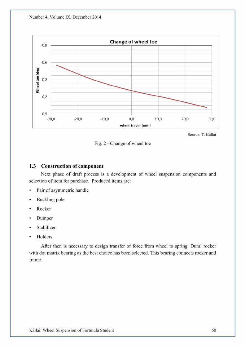
After then is necessary to design transfer of force from wheel to spring. Dural rocker with dot matrix bearing as the best choice has been selected. This bearing connects rocker and frame.
Number 4, Volume IX, December 2014
Kállai: Wheel Suspension of Fortmula Student 61
Source: T. Kállai
Fig. 3 - Rocker
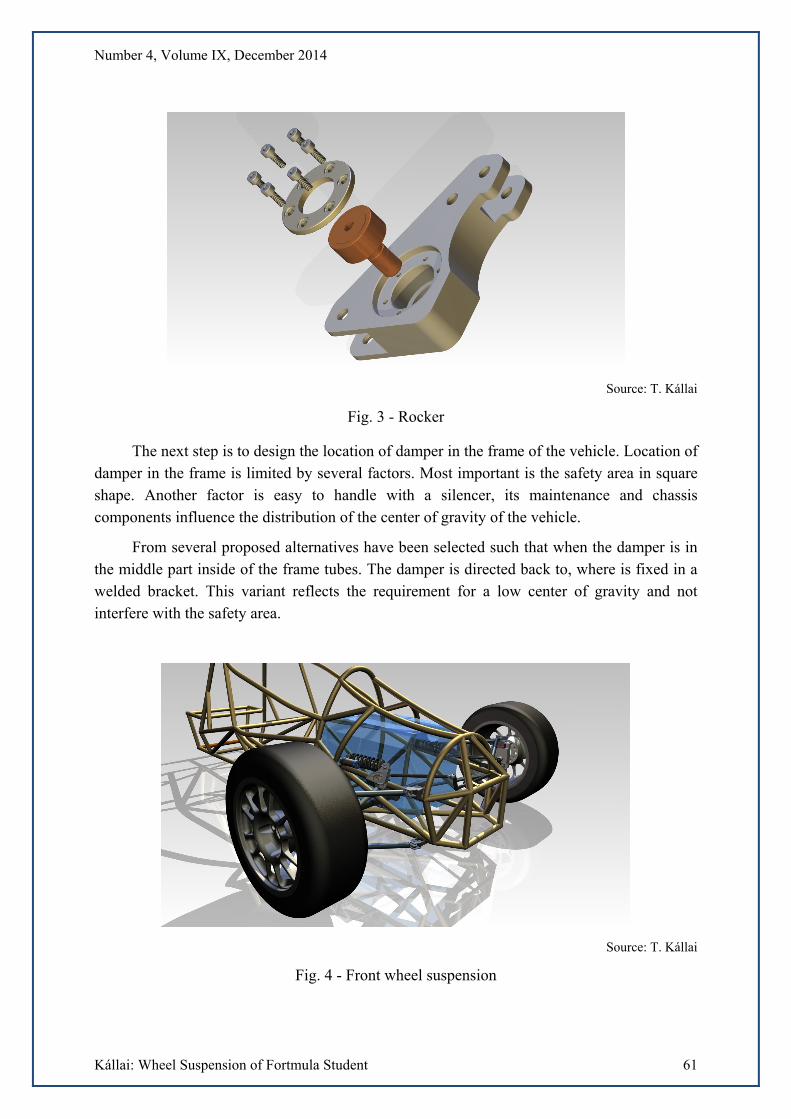
The next step is to design the location of damper in the frame of the vehicle. Location of damper in the frame is limited by several factors. Most important is the safety area in square shape. Another factor is easy to handle with a silencer, its maintenance and chassis components influence the distribution of the center of gravity of the vehicle.
From several proposed alternatives have been selected such that when the damper is in the middle part inside of the frame tubes. The damper is directed back to, where is fixed in a welded bracket. This variant reflects the requirement for a low center of gravity and not interfere with the safety area.
Source: T. Kállai
Fig. 4 - Front wheel suspension
Number 4, Volume IX, December 2014
Kállai: Wheel Suspension of Fortmula Student 62
1.4 Optimization of the components
Optimization of the components is part of the design. Optimization was based on functionality, and weight savings. The weight saving has a significant influence on driving characteristics and vehicle performance.
All suspension components was structurally modified. Pipes with smaller diameter have been selected, and it results to weight reduction of the unsprang weight of the front axle about 1.3 kilograms. The basic shape of aluminum rocker has been also modified with respect to functionality.
1.5 Checking of the proposed components
Components must be continuously designed and tested after weight optimization, because of safety requirements. The basic input for all analysis is the calculation of forces on each suspension components at different driving situations.
For the forces calculation were chosen these driving situations:
Vehicle straight line drive
Vehicle cornering
Vehicle maximum deceleration (braking) on the adhesion limit
Vehicle maximum acceleration on the adhesion limit
Source: T. Kállai
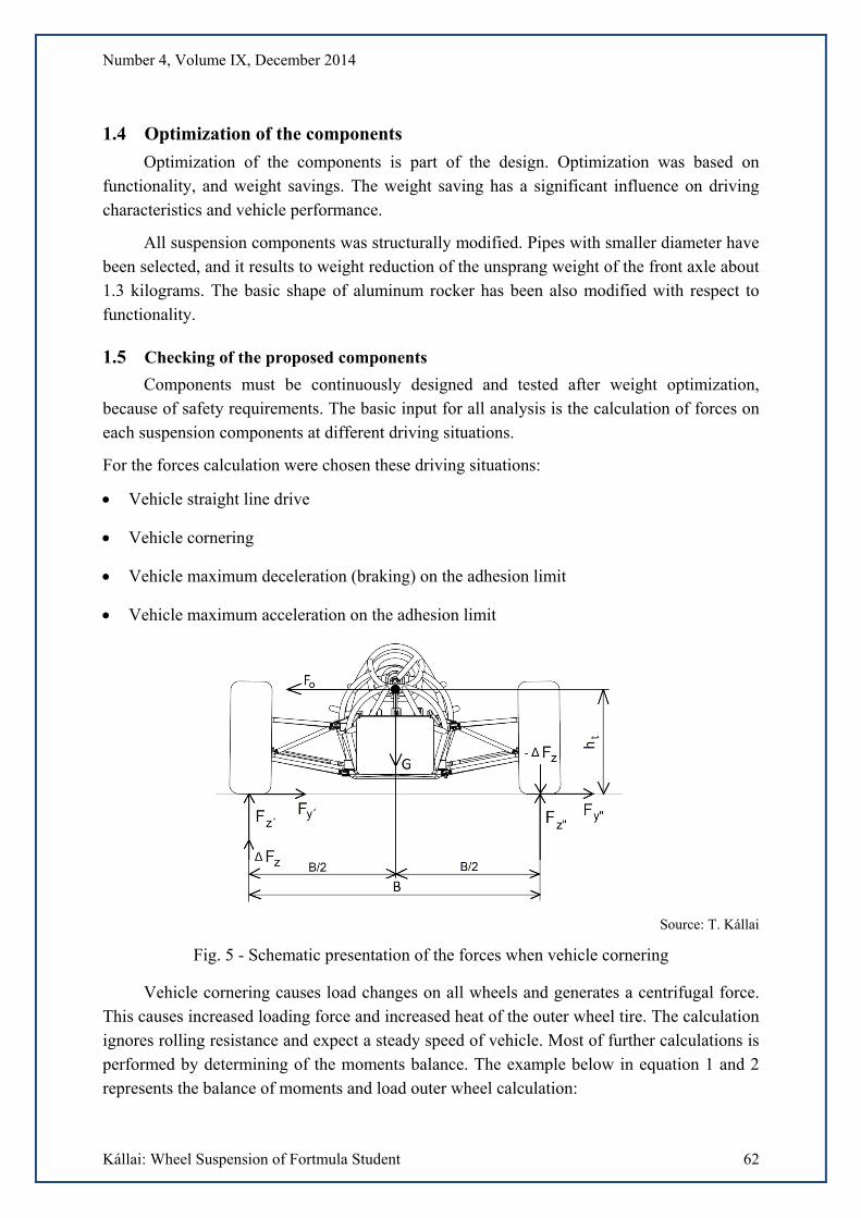
Fig. 5 - Schematic presentation of the forces when vehicle cornering
Vehicle cornering causes load changes on all wheels and generates a centrifugal force. This causes increased loading force and increased heat of the outer wheel tire. The calculation ignores rolling resistance and expect a steady speed of vehicle. Most of further calculations is performed by determining of the moments balance. The example below in equation 1 and 2 represents the balance of moments and load outer wheel calculation:
Number 4, Volume IX, December 2014
Kállai: Wheel Suspension of Fortmula Student 63
(1)
(2)
where: FZ´ –loading force on outer wheel [N] ht – center of gravity height [m] G – weight force on solved axle [N] B – track width of vehicle [m]
From this equation can be specified loading force acting on the inner wheel. Firstly must be determined wheel load difference (equation 3)
(3)
where: ΔFZ – difference between front wheels load [N] G1 – front axle load [N]
Loading force acting on the inner wheel has been determined by the following equation 4:
(4)
FZP – force exerted on the inner wheel [N]
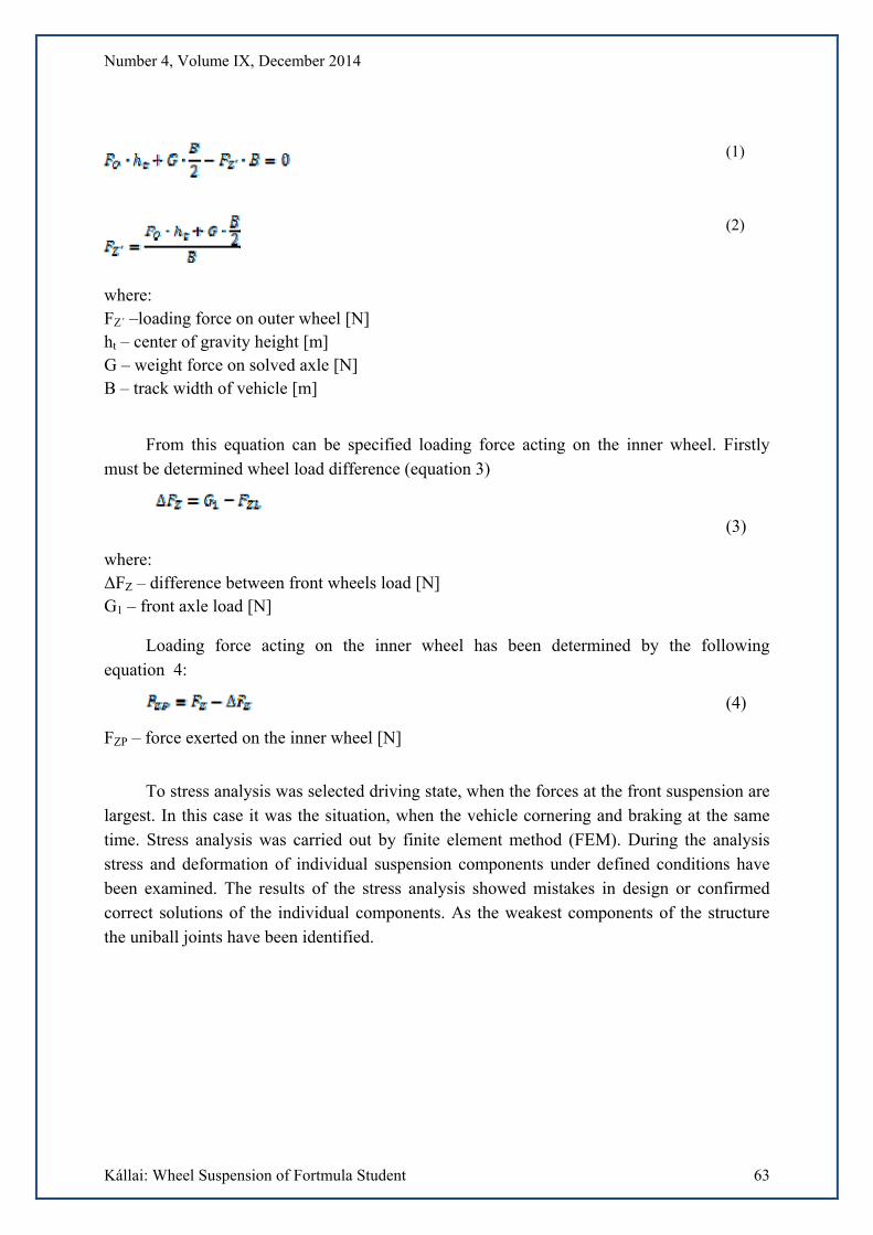
To stress analysis was selected driving state, when the forces at the front suspension are largest. In this case it was the situation, when the vehicle cornering and braking at the same time. Stress analysis was carried out by finite element method (FEM). During the analysis stress and deformation of individual suspension components under defined conditions have been examined. The results of the stress analysis showed mistakes in design or confirmed correct solutions of the individual components. As the weakest components of the structure the uniball joints have been identified.
Number 4, Volume IX, December 2014
Kállai: Wheel Suspension of Fortmula Student 64
Source: T. Kállai
Fig. 6 - Displacement and stress in the upper arm when the vehicle cornering
2. SUSPENSION OF REAR WHEELS
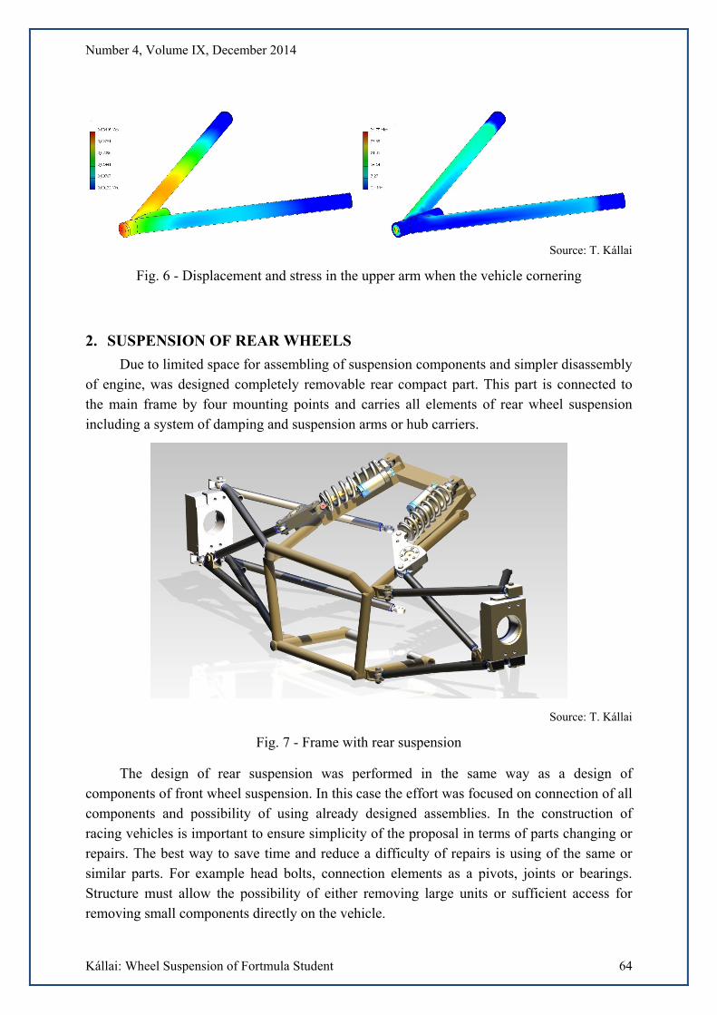
Due to limited space for assembling of suspension components and simpler disassembly of engine, was designed completely removable rear compact part. This part is connected to the main frame by four mounting points and carries all elements of rear wheel suspension including a system of damping and suspension arms or hub carriers.
Source: T. Kállai
Fig. 7 - Frame with rear suspension
The design of rear suspension was performed in the same way as a design of components of front wheel suspension. In this case the effort was focused on connection of all components and possibility of using already designed assemblies. In the construction of racing vehicles is important to ensure simplicity of the proposal in terms of parts changing or repairs. The best way to save time and reduce a difficulty of repairs is using of the same or similar parts. For example head bolts, connection elements as a pivots, joints or bearings. Structure must allow the possibility of either removing large units or sufficient access for removing small components directly on the vehicle.
Number 4, Volume IX, December 2014
Kállai: Wheel Suspension of Fortmula Student 65
To simplification of suspension system the arms of the same construction for front and rear axle have been used. Only their dimension are different. The joints of arm, bolts and threads and screws are also identical for front and rear axle. In the system of both suspension was used already designed aluminium rocker arm, it gives spare parts capacity reduction.
CONCLUSION
The article summarizes the design for suspension of student’s formula. From the article that the proposal is very extensive and includes the problems of racing car design in knowledge of the rules and basics of vehicle chassis construction. The project student formula is focused to the cooperation of students. It is important because of communication between members of the racing team. Participation at the event is the final result and goal of the year-round endeavor.
REFERENCES
(1) KÁLLAI, T. Návrh předních závěsů kol vozu Formula Student, Ostrava: Vysoká škola
báňská, Technická univerzita Ostrava, 2014
(2) RICHTÁŘ, M.;. ŠMIRAUS, J.; DRESLER, P.; - Stavba silničních vozidel, VŠB-TU
Ostrava, Univerzita Pardubice 2013
(2) VLK, František. Podvozky motorových vozidel. Brno: Prof.Ing.František Vlk, DrSc, 2006,
464 s. ISBN 80-239-6464-X.
(3) MATĚJKA, R.: Vozidla silniční dopravy II. VŠDS Žilina, Alfa Bratislava, 1981
Autozine.cz. [Online]. [cit. 2014-08-28]. Available from:
<http://www.autozine.cz/studenti-vsb-tuo-stavi-vlastni-formuli/>


![[PPT]2012 Formula SAE - Outboard Suspension - - …web.cecs.pdx.edu/~far/Past Capstone Projects/2012/FSAE... · Web view2012 Formula SAE Outboard Suspension Jose Colin EfeYildirim](https://img.pdfslide.net/doc/110x75/5ae0fda77f8b9a1c248dd44c/ppt2012-formula-sae-outboard-suspension-webcecspdxedufarpast-capstone.jpg)


![Formula SAE - Steering & Suspension Design - [ IntensePotential.com]](https://img.pdfslide.net/doc/110x75/55cf9284550346f57b970e81/formula-sae-steering-suspension-design-intensepotentialcom.jpg)