Embed Size (px)
Citation preview

HAL Id: hal-01950931https://hal.inria.fr/hal-01950931
Submitted on 17 Jan 2019
HAL is a multi-disciplinary open accessarchive for the deposit and dissemination of sci-entific research documents, whether they are pub-lished or not. The documents may come fromteaching and research institutions in France orabroad, or from public or private research centers.
L’archive ouverte pluridisciplinaire HAL, estdestinée au dépôt et à la diffusion de documentsscientifiques de niveau recherche, publiés ou non,émanant des établissements d’enseignement et derecherche français ou étrangers, des laboratoirespublics ou privés.
When fault injection collides with hardware complexitySebanjila Bukasa, Ludovic Claudepierre, Ronan Lashermes, Jean-Louis Lanet
To cite this version:Sebanjila Bukasa, Ludovic Claudepierre, Ronan Lashermes, Jean-Louis Lanet. When fault injectioncollides with hardware complexity. FPS 2018 - 11th International Symposium on Foundations &Practice of Security, Nov 2018, Montréal, Canada. p.243-256, �10.1007/978-3-030-18419-3_16�. �hal-01950931�
When fault injection collides with hardwarecomplexity
Sebanjila Kevin Bukasa1, Ludovic Claudepierre1, Ronan Lashermes1,and Jean-Louis Lanet1
LHS INRIA{first.last}@inria.fr
Abstract. Fault Injections (FI) against hardware circuits can make asystem inoperable or lead to information security breaches. FI can beused preemptively in order to detect and mitigate weaknesses in a de-sign. FI is an old field of study and therefore numerous techniques andtools can be used for that purpose. Each technique can be used at dif-ferent levels of circuit design, and has strengths and weaknesses. In thispaper, we review these techniques to show their pros and cons and moreprecisely we highlight their shortcomings with respect to the complexityof modern systems.
1 Introduction
In the field of hardware security, Fault Injection (FI) is a technique toalter the correct execution of a program in a chip. The resulting errors canbe harnessed in order to weaken the security of the device, by extractingcryptographic keys for example. In the case of hardware security, thedistinction between errors (the internal system state is erroneous) andfailures (the behaviour does not follow specifications) is blurred. Indeed,the attacker can observe, or deduce, the state of the device though itsinteraction with the environment; thus it is considered that the attackercan observe errors and exploit them. For example, a timing attack canleak a password during its verification. It is therefore common to use theterm errors to designate either errors or failures.
A fault may be caused by radiation (laser pulses, electromagneticpulses, alpha particles, . . . ), power glitches, clock glitches, abnormal tem-peratures, etc. Faults are naturally found in hardware, but can also bevoluntarily caused by an attacker. In all cases, they can often be exploitedfor malicious activities. Therefore faults must be mitigated.
FI can be used to infer the faults that can be created in a system, toanalyse the errors created as a consequence and whether they make thesystem vulnerable. The difficulty is in the trade-off between the size of the

state space to explore and the speed of the analysis. We will show thatthe complexity of modern system renders FI tools less precise becausethey cannot accurately model the erroneous states.
In this paper, after a context presentation in section 2, we reviewthe techniques and tools to assess the vulnerability of a device to FIin section 3. The shortcomings of actual techniques will be presented insection 4 as well as a discussion on how to improve them. Finally, theconclusion is drawn in section 5.
2 Context safety/security
FI is an old research discipline [1,2,3,4], which originates from the studyof fault tolerant systems, mainly from aerospace. FI is defined by Arlat [5]as a validation technique of dependability for fault tolerant systems. Itconsists in observing system behaviour in presence of faults defined witha fault model. At the beginning, FI was applied on hardware components.Consequently, corresponding fault models were comprised of effects thatwere deemed representative for failing logic elements, in particular stuck-at logical zero or one. One would be able to inject a fault at transistorlevel which models an unintended physical effect, such as a signal tran-sition caused by a heavy ion hit and resulting in a communication errorat system level for example. While this approach is close to reality, apractical implementation is barely possible.
All FI techniques aim to solve several problems:
– Injection of faults;
– Observation of their effects;
– Intrusiveness of the solution;
– Capacity to explore the entire state space.
The FI techniques have been recognized for a long time necessaryto validate the dependability of a system by analysing the behaviour ofdevices when a fault occurs. More recently, secure devices have to facefault attacks which are similar to failure problems. Efforts have beenmade to develop techniques for injecting faults into a system prototypeor model.
When considering information security, fault injection assumes thatthe attacker is able to target specific assets in the system. It means thatshe knows exactly what kind of behaviour she requires to reach her goal.In case of targeting cryptographic algorithms [6,7] or assets (keys, tokens,. . . ) several solutions have been proposed to protect them against fault
2

injections [8]. Applications can be designed to be resilient against FI, butthis resilience mainly focus on software execution of these applications, insome cases this can be a problem, indeed a complete confidence is givento hardware.
3 Fault Injection techniques
Several techniques exist to inject faults, all of them with advantages anddisadvantages. Here is an overview of these techniques.
3.1 Hardware-based FI
Hardware based FI aims at disturbing hardware with physical and en-vironmental parameters (heavy ion radiation, electromagnetic interfer-ences [9], etc.), injecting voltage dips on power rails [10,11] laser faultinjection [12] or modifying the value of some pins with circuit editing.The main advantage of this family of techniques over the other solutionsis that they evaluate the final device. To achieve this kind of FI it isnecessary to possess a final version of the evaluated device.
The effects of physical injections are difficult to control and repeata-bility of experiment is hard to achieve. To obtain repeatability, insteadof injecting physically a fault, injection mechanisms emulate effects ofphysical perturbations on hardware such as pin-level FI [13].
Fault Injection system for Study of Transient fault effects (FIST) usesheavy-ion radiation or power disturbance faults to create faults inside achip when it is exposed to radiation. It can cause single or multiple bit-flips producing transient faults at random locations directly inside a chip,which cannot be done with pin-level injections.
Messaline [5] is a pin-level fault forcing system. It uses both activeprobes and sockets to conduct pin-level fault injection. It can inject stuck-at, open, bridging and complex logical faults, among others. It can alsotune the duration of the fault existence and its frequency. RIFLE [14] isalso a pin-level fault injection system for dependability validation. Thissystem can be adapted to a wide range of target systems and faults aremainly injected in processor pins. FI is deterministic and can be repro-duced if needed. Different kind of faults can be injected and the faultinjector is able to detect whether the injected fault has produced an erroror not without specific hardware.
Obviously, hardware-based tools are also hardware dependent. Fur-thermore, the setup of these hardware-based injectors is rather complex.
3
3.2 Simulation-based FI
Simulation based hardware fault injection techniques simulate hardwaredescription of tested circuit using high-level models (mostly HardwareDescription Language (HDL) models). It consists in injecting faults intothat model to evaluate their impacts. Most of the tools modify the hard-ware description of tested circuit to include the components necessary toinject faults. These fault injection components can be designed to injectdifferent fault behaviours depending on the fault model. Faults can also beinjected using hardware description language simulator commands whichallow variables and signals of circuit being modified.
A major disadvantage of simulation based techniques is that they areextremely slow. Simulating the register transfer level (RTL) descriptionof a circuit is multiple orders of magnitude slower than actual circuitoperation speed. Hence, even for relatively small processors, simulationbased fault injection tools can only evaluate fault propagation for a veryshort time interval.
VERIFY [15] (VHDL-based Evaluation of Reliability by InjectionFaults Efficiently) uses an extension of VHDL for describing faults corre-lated to a component, enabling hardware manufacturers to express theirknowledge of fault behaviour on their components. Multi-threaded faultinjection which uses checkpoints and comparison with a golden run is usedfor faster simulation of faulty runs. Proposed extension to VHDL languageunfortunately requires modification on language itself. VERIFY uses anintegrated fault model which cannot be extended.
MEFISTO-C [16] conducts fault injection experiments using VHDLsimulation models. The tool is an improved version of MEFISTO toolwhich was developed jointly by LAAS-CNRS and Chalmers. MEFISTO-C uses a VHDL simulator and injects faults via simulator commandsin variables and signals defined by a VHDL model. It offers to users avariety of predefined fault models as well as other features to set-up andautomatically conduct fault injection campaigns.
FAUMachine [17] is a tool allowing simulation of complete systems, itwas the main core for different works in the field of fault injections [18,19].Its particularity is that it allows to simulate various types of faults andin various devices connected to the system, while making possible theobservation of the impacts on the total operation of the system
4

3.3 Emulation-based FI
System emulation uses hardware prototyping on Field ProgrammableGate Arrays (FPGA) based logic emulation systems [20], [21]. This tech-nique has been presented as an alternative solution in order to reducetime spent during simulation-based fault injection campaigns.
This technique allows designer to study the actual behaviour of cir-cuits in application environment, taking into account real-time interac-tions. However, when an emulator is used, initial VHDL description mustbe complete and fully synthesizable. Modified circuit contains sequencesof operations which can flip their output bit based on a control signalvalue. Such techniques require an additional control mechanism to specifytime and location of fault injection in circuit. If such a control mechanismis implemented in circuit, its complexity increases with number of faultinjectable memory elements.
Antoni et al. [22] proposed a technique to inject a fault on chosenmemory elements at run time on a FPGA using runtime reconfiguration.This eliminates the need for having a complex control circuit to determineinjection location. However, the time required to reconfigure the circuitcould be significant when compared to the total application run time.
Civera et al. [20] proposed another solution to provide a more flexiblecontrol over runtime fault injection. They used modified flip-flop circuitscapable of injecting faults based on a control bit associated with eachflip-flop. All these control bits are tied together like a scan-chain and atrun time can be programmed to inject fault in any desired flip-flop in thecircuit.
3.4 Software implemented FI
The objective of these techniques consists in reproducing at software levelerrors that would have been produced by faults at hardware level. Theyare mostly used in order to detect and predict vulnerabilities with respectto hardware fault injection. Software implemented fault injection (SWIFI)tools use a software level abstraction of fault models in order to injecterrors in software while it runs or by modifying programs before execution.This approach does not need any hardware modification. SWIFI providesa way to test complete systems including the operating system and theapplicative layer. This makes SWIFI techniques quite popular and a largenumber of such tools exists, Table 1 summarizes some of them and exploretheir particularities.
The most common fault models are:
5

Table 1. Overview of some SWIFI techniques
SWIFI technique Fault model Fault target Injection point
CEU [23] Bit flip Variables Runtime(interruptions)
DOCTOR [24] Bit flips Communications,variables
Preruntime
EFS [25] Bit flips, codeinsertion, datamodifications
Control flow,variables
Runtime (OSservice)
FERRARI [26] Address, data orflags modifications
Control flow,variables
Runtime (parallelprocess)
FIES [27] Bit flip, bridgingand stuck-at faults
Control flow,variables
Runtime
XCEPTION [28] Bit flip, bridgingand stuck-at faults
Variables Runtime(interruptions)
– instruction skip (one or several instructions are not executed),– instruction modification (one or several instructions are modified ac-
cording to a pattern such as single bit-flip, random change, . . . ).
Common software mechanisms used for run time FI, such as pertur-bation functions require a modification of the program. Unfortunately,this extra instrumentation causes execution overhead that will affect thesystem behaviour (speed, memory consumption, . . . ). For example, FER-RARI [26] and EFS [25] tools require some context switches between itsfault injection process and target system process.
A common problem with run time approach is the intrusiveness whichrefers to the alteration of the original system due to fault injection ex-periment setup (e.g. changes in program flow, additional components,temporal variation,...). Depending on the actual intention of fault injec-
6

tion, respective tools have to cope with completely different requirements.In contrast to an ideal tool which always provides low intrusiveness, highvisibility and high performance, available tools are only specialized on asubset of these requirements.
The major drawback of SWIFI is related to state space problem. Thetools often generate much more faults than any other techniques (sincethe abstraction level has a richer representation, i.e. there may be 232
possible instruction values in a 32-bit system and less that 232 wires inthe chip). Yet most of the time generated faults do not lead to failures,the error may have been silently suppressed during the execution. Thechallenge is to either generate only a minimal set of faults (those thatcan lead to a Silent Data Corruption) or to prune them while they aregenerated. This leads to several optimization phases during simulationand remains a difficult challenge.
In the context of information security, errors can often be exploitedeven in the absence of failures. An error can cause copying of a secret in avulnerable part of memory for example. Since SWIFI tools use a softwarelevel abstraction of fault models, they cannot capture such vulnerabilities.
4 Techniques validity
We consider ourselves as evaluators. When it comes to FI, we want toevaluate if a technique is more appropriate in order to evaluate behaviourof a device when a fault occur.
Various injection means exist and several techniques have been usingthem in different way and targeting several type of devices. Since simula-tion and emulation based techniques require a white-box model (access toHDL sources, . . . ) that are most of the time not available to evaluators.
In this section we limit ourselves to hardware-based and software-based injections techniques.
4.1 Experiences
In order to test the consistency of SWIFI models, in particular theirsoftware level abstraction of fault models with real observations, we con-ducted different experiments, which we will present here.
Faustine platform Our platform, called Faustine 1, is made of a Keysight33509B pulse generator, a Keysight 81160A signal generator and a Milmega
7

80RF1000-175 power amplifier, connected in sequence to generate a sig-nal. This signal then passes through a Langer RF probe RF B 0.3-3 lo-cated on the targeted chip to generate an Electromagnetic Fault Injection(EMFI).
Fig. 1. Overview of Faustine platform
In order to launch a fault injection, a synchronization signal (a trig-ger) is sent by the targeted chip General-Purpose Input/Output (GPIO)(controlled from the code) directly to the 33509B pulse generator. Thisexperimental trick, possible when the attacker has control of the code(i.e. only for vulnerability assessment) is not mandatory. Other synchro-nization possibilities include sniffing communications with the target ormeasuring its EM emissions to find a relevant pattern.
The location of the probe on the chip was chosen after a scan thatdetermined the most sensitive area on the chip. The same location waskept for all experiments.
Microcontroller We first analyse a Microcontroller (µC). The targetedboard is an STM32VLDISCOVERY board with an STM32F100RB chip,
8

embedding an ARM Cortex-M3 core running at 24MHz (41.7ns clockperiod). As shown in Figure 2, probe is just on top of the chip.
Fig. 2. STM32 under probe
On this board the tested software is a PIN code checker, the enteredPIN code is compared with the internal PIN code if it is false (false=1in 1.1), the status variable takes the value 0xFFFFFFFF, otherwise it takes0x55555555. Thus in the first case, access will be denied, in the secondit will be granted.
if(false == 1) {
status = 0xFFFFFFFF; }
else {
status = 0x55555555; }
Listing 1.1. Targeted C code
cmp r3, #1 ; r3 contains *false*
ite eq ; if then else
moveq.w r4, #4294967295 ; 0xFFFFFFFF
movne.w r4, #1431655765 ; 0x55555555
Listing 1.2. Resulting assembly (thumb2)
9

As we can see on listing 1.2, in order to modify the behaviour of theprogram and thus get access without the PIN code, we can target the ifthen else (ite) instruction. If it is possible to not execute it, then the nexttwo instructions will execute in sequence and, as their result is stored inthe same register (r4), only the second assignment will have an impact(overwriting the first one).
In the case of SWIFI, we consider the software level abstraction offault model by deleting (manual edition of the binary) this instructionwhich allows us to see that it is indeed the right target, then we targetthe execution of this instruction with a hardware fault.
In this way, when we inject our fault, we try to synchronize with thecode snippet in listing 1.2 and target the instruction ite eq. In 10% ofthe cases, the execution is faulty (status = 0x5555555), proving thatthe SWIFI allows us in this case to find a point of sensitivity and thus toinject our fault effectively.
However, we found that different timings (over a span of 5 instruc-tions) were able to get our faulty behaviour. This can have several plau-sible explanations, such as the fact that several different skipped instruc-tions can lead to the same impact, or that the ite eq instruction can beimpacted at different levels of its execution pipeline.
System-on-Chip We then analysed a System-on-Chip (SoC). The tar-geted board is a Raspberry Pi3 board with a BCM2837 chip, which em-beds 4 ARM Cortex-A53 cores, running at up to 1.2 GHz (833ps clockperiod).
while(1){
wait(x*desynch value+x);
turn_on_LED(y);
wait(x*activation duration+x)
turn_off_LED(y);
}
Listing 1.3. Targeted C code
Here we want to evaluate the impact of a fault and compare it to theSWIFI models. The goal is to see if a hardware generated fault can beexplained by a software abstraction of the fault model, represented bysoftware modification. Thus we inject faults at different timings duringthe execution of a loop (listing 1.3) on 2 of the 4 cores, others being usedto communicate with the host, while desynchronizing them (they are notstarted at the same time). The 2 cores (x) are activating their own signal
10
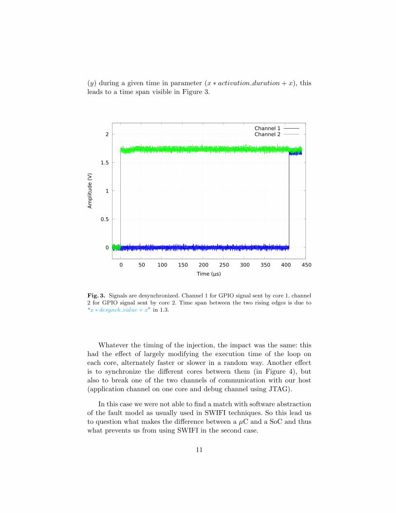
(y) during a given time in parameter (x ∗ activation duration+ x), thisleads to a time span visible in Figure 3.
0
0.5
1
1.5
2
0 50 100 150 200 250 300 350 400 450
Am
plitu
de (
V)
Time (µs)
Channel 1Channel 2
Fig. 3. Signals are desynchronized. Channel 1 for GPIO signal sent by core 1, channel2 for GPIO signal sent by core 2. Time span between the two rising edges is due to“x ∗ desynch value + x” in 1.3.
Whatever the timing of the injection, the impact was the same: thishad the effect of largely modifying the execution time of the loop oneach core, alternately faster or slower in a random way. Another effectis to synchronize the different cores between them (in Figure 4), butalso to break one of the two channels of communication with our host(application channel on one core and debug channel using JTAG).
In this case we were not able to find a match with software abstractionof the fault model as usually used in SWIFI techniques. So this lead usto question what makes the difference between a µC and a SoC and thuswhat prevents us from using SWIFI in the second case.
11

0
0.5
1
1.5
2
0 50 100 150 200 250 300 350 400 450
Am
plitu
de (
V)
Time (µs)
Channel 1Channel 2
Fig. 4. Signals are shorter and synchronized. First, time span seems to have disap-peared, then “x ∗ activation duration+ x” (in 1.3) seems to have changed to be equalin the 2 cores.
4.2 System complexity
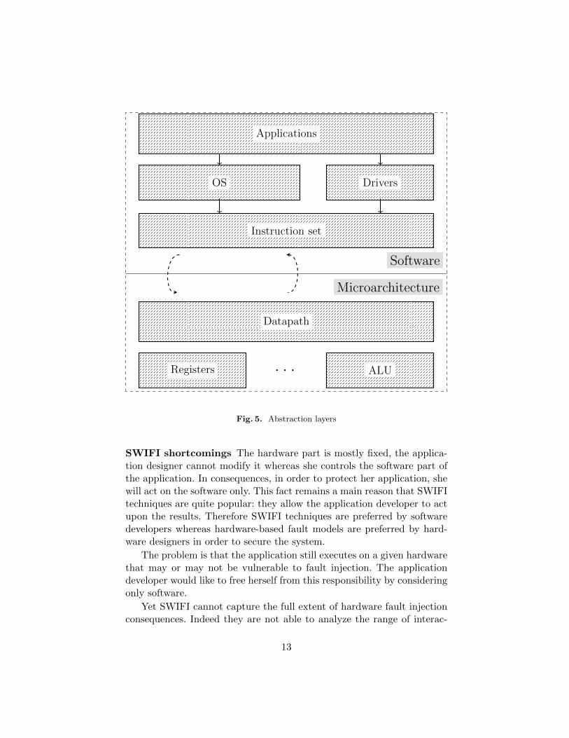
Abstraction layers A computing system is a complex device. In orderto allow humans to build mental models of how such systems work, thiscomplexity is often hidden behind abstraction layers as visible in Figure 5.
There is a main division between these layers corresponding to thehardware/software interface constituted by the Instruction Set Architec-ture (ISA). On the upper side, software is constituted of a successionof instructions. On the lower side, the micro-architecture (hardware) isresponsible for upholding this abstract representation.
The micro-architecture is widely different if we consider a µC or aSoC. In the first case, the instruction execution flow is quite simple, witha single core, a simple memory hierarchy, in-order execution, etc. In thecase of a SoC, the micro-architecture can be quite complex. Several corecan share the same memory space, with a complex memory hierarchy(several cache levels, shared or not). Instructions can be executed out-of-order or even speculatively. What happens in hardware differs from thesimple model provided by the ISA.
12
Software
Microarchitecture
Instruction set
OS Drivers
Applications
Datapath
Registers ALU. . .
Fig. 5. Abstraction layers
SWIFI shortcomings The hardware part is mostly fixed, the applica-tion designer cannot modify it whereas she controls the software part ofthe application. In consequences, in order to protect her application, shewill act on the software only. This fact remains a main reason that SWIFItechniques are quite popular: they allow the application developer to actupon the results. Therefore SWIFI techniques are preferred by softwaredevelopers whereas hardware-based fault models are preferred by hard-ware designers in order to secure the system.
The problem is that the application still executes on a given hardwarethat may or may not be vulnerable to fault injection. The applicationdeveloper would like to free herself from this responsibility by consideringonly software.
Yet SWIFI cannot capture the full extent of hardware fault injectionconsequences. Indeed they are not able to analyze the range of interac-
13

tions and components present at the hardware level (the microarchitec-ture in 5) by abstracting the behaviour at the software level. Considera Direct Memory Access (DMA) transfer for example. In this case, asection of memory is copied to another without the Central ProcessingUnit (CPU) involvement. Instructions are present to describe the desiredmemory transfer then it is enforced in parallel of the program execution.Therefore, any fault on the DMA transfer cannot be captured by a SWIFItechnique.
Complexity evolution It can be argued that cases that cannot becaptured by SWIFI, such as DMA transfers, are special cases not repre-sentative of classical applications.
But as we have show in section 4.1, if these asynchronous behavioursare seldom present in simple systems, they are ubiquitous in modern SoCs.In order to squeeze the maximum performance out of modern SoCs, a lotof processing is done in parallel of the instruction flow execution.
The recent trend is in more complex systems, not simpler. As a con-sequence, SWIFI techniques are less and less able to capture the extentof possible errors in these systems.
5 Conclusions
FI tools are quite useful in the context of dependability and informationsecurity. They can be used to assess the security of a system with respectto fault attacks. Application developers mostly use SWIFI tools to predictthe behaviour of their program in the event of a fault according to asoftware abstraction of the fault model. However, we have seen that thepart targeted by the fault attacks is at the microarchitecture level which isthe physical representation of the system, we have seen that in the case ofa simple system, such as an µC (also in [29,30]), it was possible to find anabstraction at the software level of behaviour occurring at the hardwarelevel. Nevertheless, through the experiments we conducted it appearedto us that on systems where the microarchitecture is more complex, asin the case of the SoC it became complex to find an abstraction at thesoftware level of the models of faults corresponding to those generallyconsidered by SWIFI methods (bit-flip, stuck-at, skip instruction, etc.).As a consequence, SWIFI is less and less relevant for such systems.
14

References
1. F. H. Hardie and R. J. Suhocki, “Design and use of fault simulation for saturncomputer design,” IEEE Transactions on Electronic Computers, no. 4, pp. 412–429, 1967.
2. D. Armstrong, “A deductive method for simulating faults in logic circuits,” IEEETransactions on Computers, vol. 21, no. undefined, pp. 464–471, 1972.
3. E. G. Ulrich, T. Baker, and L. Williams, “Fault-test analysis techniques based onlogic simulation,” in Proceedings of the 9th Design Automation Workshop. ACM,1972, pp. 111–115.
4. P. R. Menon and S. G. Chappell, “Deductive fault simulation with functionalblocks,” IEEE Transactions on Computers, vol. 27, no. 8, pp. 689–695, 1978.
5. J. Arlat, “Validation de la surete de fonctionnement par injection de fautes,methode- mise en oeuvre- application,” Ph.D. dissertation, 1990.
6. M. Joye and M. Tunstall, Fault analysis in cryptography. Springer, 2012, vol. 147.7. R. Lashermes, J. Fournier, and L. Goubin, “Inverting the final exponentiation of
tate pairings on ordinary elliptic curves using faults,” in International Workshopon Cryptographic Hardware and Embedded Systems. Springer, 2013, pp. 365–382.
8. A. Barenghi, L. Breveglieri, I. Koren, and D. Naccache, “Fault injection attackson cryptographic devices: Theory, practice, and countermeasures,” Proceedings ofthe IEEE, vol. 100, no. 11, pp. 3056–3076, Nov 2012.
9. N. Moro, A. Dehbaoui, K. Heydemann, B. Robisson, and E. Encrenaz, “Electro-magnetic fault injection: towards a fault model on a 32-bit microcontroller,” arXivpreprint arXiv:1402.6421, 2014.
10. N. Timmers, A. Spruyt, and M. Witteman, “Controlling pc on arm using fault in-jection,” in Fault Diagnosis and Tolerance in Cryptography (FDTC), 2016 Work-shop on. IEEE, 2016, pp. 25–35.
11. M. Tunstall, D. Mukhopadhyay, and S. Ali, “Differential fault analysis of the ad-vanced encryption standard using a single fault,” in Information Security Theoryand Practice. Security and Privacy of Mobile Devices in Wireless Communication,C. A. Ardagna and J. Zhou, Eds. Berlin, Heidelberg: Springer Berlin Heidelberg,2011, pp. 224–233.
12. S. Buchner, D. Wilson, K. Kang, D. Gill, J. Mazer, W. Raburn, A. Campbell,and A. Knudson, “Laser simulation of single event upsets,” IEEE Transactions onNuclear Science, vol. 34, no. 6, pp. 1227–1233, 1987.
13. J. Arlat, M. Aguera, L. Amat, Y. Crouzet, J.-C. Fabre, J.-C. Laprie, E. Martins,and D. Powell, “Fault injection for dependability validation: A methodology andsome applications,” IEEE Transactions on Software Engineering, vol. 16, no. 2,pp. 166–182, 1990.
14. H. Madeira, M. Rela, F. Moreira, and J. G. Silva, “Rifle: A general purpose pin-level fault injector,” in European Dependable Computing Conference. Springer,1994, pp. 197–216.
15. V. Sieh, O. Tschache, and F. Balbach, “Verify: Evaluation of reliability using vhdl-models with embedded fault descriptions,” in Fault-Tolerant Computing, 1997.FTCS-27. Digest of Papers., Twenty-Seventh Annual International Symposium on.IEEE, 1997, pp. 32–36.
16. P. Folkesson, S. Svensson, and J. Karlsson, “A comparison of simulation basedand scan chain implemented fault injection,” in Fault-Tolerant Computing, 1998.Digest of Papers. Twenty-Eighth Annual International Symposium on. IEEE,1998, pp. 284–293.
15

17. V. Sieh, “Faumachine.” [Online]. Available: http://www3.informatik.uni-erlangen.de/EN/Research/FAUmachine/description.shtml
18. S. Potyra, V. Sieh, and M. D. Cin, “Evaluating fault-tolerant system designs usingfaumachine,” in Proceedings of the 2007 workshop on Engineering fault tolerantsystems. ACM, 2007, p. 9.
19. M. Sand, S. Potyra, and V. Sieh, “Deterministic high-speed simulation of complexsystems including fault-injection,” in 2009 IEEE/IFIP International Conferenceon Dependable Systems & Networks. IEEE, 2009, pp. 211–216.
20. P. Civera, L. Macchiarulo, M. Rebaudengo, M. S. Reorda, and A. Violante, “Ex-ploiting fpga for accelerating fault injection experiments,” in On-Line TestingWorkshop, 2001. Proceedings. Seventh International. IEEE, 2001, pp. 9–13.
21. R. Leveugle, “Fault injection in vhdl descriptions and emulation,” in Proceedings-IEEE-International-Symposium-on-Defect-and-Fault-Tolerance-in-VLSI-Systems.IEEE Comput. Soc, Los Alamitos, CA, USA, 2000, pp. 414–19.
22. L. Antoni, R. Leveugle, and M. Feher, “Using run-time reconfiguration for faultinjection in hardware prototypes,” in Defect and Fault Tolerance in VLSI Systems,2002. DFT 2002. Proceedings. 17th IEEE International Symposium on. IEEE,2002, pp. 245–253.
23. R. Velazco, S. Rezgui, and R. Ecoffet, “Predicting error rate for microprocessor-based digital architectures through c.e.u. (code emulating upsets) injection,” IEEETransactions on Nuclear Science, vol. 47, no. 6, pp. 2405–2411, Dec 2000.
24. S. Han, K. G. Shin, and H. A. Rosenberg, “Doctor: An integrated software fault in-jection environment for distributed real-time systems,” in Computer Performanceand Dependability Symposium, 1995. Proceedings., International. IEEE, 1995, pp.204–213.
25. L. Riviere, J. Bringer, T.-H. Le, and H. Chabanne, “A novel simulation approachfor fault injection resistance evaluation on smart cards,” in Software Testing, Ver-ification and Validation Workshops (ICSTW), 2015 IEEE Eighth InternationalConference on. IEEE, 2015, pp. 1–8.
26. G. A. Kanawati, N. A. Kanawati, and J. A. Abraham, “Ferrari: A flexible software-based fault and error injection system,” IEEE Transactions on computers, vol. 44,no. 2, pp. 248–260, 1995.
27. A. Holler, T. Rauter, J. Iber, and C. Kreiner, “Diverse compiling for microproces-sor fault detection in temporal redundant systems,” in 2015 IEEE InternationalConference on Computer and Information Technology; Ubiquitous Computing andCommunications; Dependable, Autonomic and Secure Computing; Pervasive Intel-ligence and Computing, Oct 2015, pp. 1928–1935.
28. J. Carreira, H. Madeira, J. G. Silva et al., “Xception: Software fault injectionand monitoring in processor functional units,” Dependable Computing and FaultTolerant Systems, vol. 10, pp. 245–266, 1998.
29. B. Yuce, N. F. Ghalaty, and P. Schaumont, “Improving fault attacks on embeddedsoftware using risc pipeline characterization,” in Fault Diagnosis and Tolerance inCryptography (FDTC), 2015 Workshop on. IEEE, 2015, pp. 97–108.
30. L. Riviere, Z. Najm, P. Rauzy, J.-L. Danger, J. Bringer, and L. Sauvage, “Highprecision fault injections on the instruction cache of armv7-m architectures,” arXivpreprint arXiv:1510.01537, 2015.
16