Embed Size (px)
Citation preview

22 GEARS May/June 2011
Which Is More Important: How It Works or What’s Wrong With It?
It’s Monday morning and as you’re walking up to your bay you see a late model GMC sitting there.
“There’s an Allison transmission in that truck,” you might say to yourself. Then the question: “I wonder what’s wrong with it?” You find out later the com-plaint is no power.
Before the test drive you perform a quick inspection, check for codes, and make sure the vehicle is ready to drive. It has multiple codes; you record them and clear them from memory. During the test drive the vehicle goes in limp mode. Back at the shop, five min-utes later, you find the wiring harness pinched (figure 1). Two hours later the vehicle is fixed.
Quick fixes like these are always great to learn about in seminars and training classes. But understanding how the transmission operates — and why the quick fix worked in the first place — is just as important. But sometimes this transmission can fool you, like give you a false Neutral. Let’s take a look at how and why the Allison goes into fails and what causes it.
Understanding a False Neutral
If power is interrupted while the transmission is operating in reverse or neutral, the transmission defaults to or continues neutral operation. At that point you can turn the engine off and start it again: The shift selector will provide reverse, neutral, and drive capability regardless of the range it was in when the failure occurred.
In this state, pressure control sole-noid 1 — PCS1 or trim A solenoid — is de-energized, and allows the 3rd, 5th and reverse clutches to apply. If you move the selector valve into reverse,
Technically Speaking
Allison… is that you?
Figure 1
Figure 2
by Lance Wigginsmembers.atra.com
www.atra.com

24 GEARS May/June 2011
Which Is More Important: How It Works or What’s Wrong With It?
main pressure is routed to the low and reverse clutch, allowing reverse opera-tion.
If you move the selector valve to drive, main pressure is routed to the 1-2-3-4 clutch, allowing 3rd gear operation. If the unit has no forward or reverse, or won’t move at all, follow these steps:
• Set the parking brake.• Key off.• Disconnect the case connector
at the transmission.• Using a fused jumper wire, con-
nect terminal R (black/white) of the automatic transmission 20-way connector to a known good ground.
• Start the engine and move the range selector to reverse — the transmission should engage reverse.
• Move the range selector to drive — the transmission should engage 3rd gear.
If reverse and 3rd gears are avail-able in limp home mode, it may indi-cate an electrical failure. If only one or neither of the ranges work, it may indicate an internal hydraulic failure such as one of these conditions:
• Failed clutch• Stuck valve• Solenoid failure• 1-2-3-4 clutch, 3rd, 5th and
reverse clutch, and the low and reverse clutch
Erratic Operation after Repair
If you’re experiencing erratic transmission operation after a rebuild or a battery disconnect, it’s important to verify in which particular gears the erratic operation is occurring.
Use a scan tool to determine these
shift sequences. If the shift timing between two gears isn’t met, the TCM will attempt to adapt the timing of that shift within the program specifications. The vehicle will need to be driven more, specifically performing that shift. Many times this will correct the condi-tion.
It’s possible to reset individual shifts without affecting the other shifts. Monitor the adaptive cells on the scan tool to determine if the adaptive strate-gies have been met.
Always reset the TCM to base cali-bration and fast adapt for all shifts. This can be done in one step with fast learn. If you miss this step, the TCM adaptive values will be at their previous settings, set to slow adaptive mode. Under these conditions, it’ll take an unacceptably long time for the adaptive values to adjust for the new transmission.
Checking the Pressure for Diagnostic Purposes
Checking mainline pressure helps determine if a transmission failure is due to a mechanical or an electrical condition (figure 2).
Caution: Keep the brakes applied at all times to prevent unexpected vehi-cle motion. Personal injury may result if the vehicle moves unexpectedly.
• Engine off.• Remove the oil pressure tap
plug.• Install the oil pressure gauge.
All transmission fluid level and pressure checks must be made at normal operating temperatures 71-93ºC (160-200ºF).
• Start the engine.• Check the transmission fluid
level; adjust if necessary.• Use the scan tool to check the
Figure 3
Figure 4

GEARS May/June 2011 25
engine RPM. • With the brakes applied, record
the line pressure values with the engine at 600 RPM, in neutral and reverse. The transmission will be in converter mode: torque converter clutch not applied.
• With the brakes applied, record the line pressure values with the engine at 2100 RPM in neutral. The transmission will be in con-verter mode: torque converter clutch not applied.
• With the brakes applied, use your scan tool to check pressures in first through fifth gear ranges at 600 RPM. The transmission will be in converter mode: torque converter clutch not applied.
• Compare the data recorded to the line pressure specifications (figures 3).
• Engine off.• Disconnect the oil pressure
gauge.• Install the oil pressure tap plug.
Problems and FixesWe’ve covered the basics; now
let’s cover the problems and fixes. Code P0842 (Transmission Fluid
Pressure (TFP) Switch 1 Solenoid Circuit Low Voltage)
Code P0847 (Transmission Fluid Pressure (TFP) Switch 2 Solenoid Circuit Low Voltage) DTC
Code P0872 (Transmission Fluid Pressure (TFP) Switch 3 Solenoid Circuit Low Voltage)
These codes can be caused by a fault in a clutch circuit, the valve body, a shift solenoid, or a faulty pressure switch circuit. These codes may be hard faults or intermittent codes.
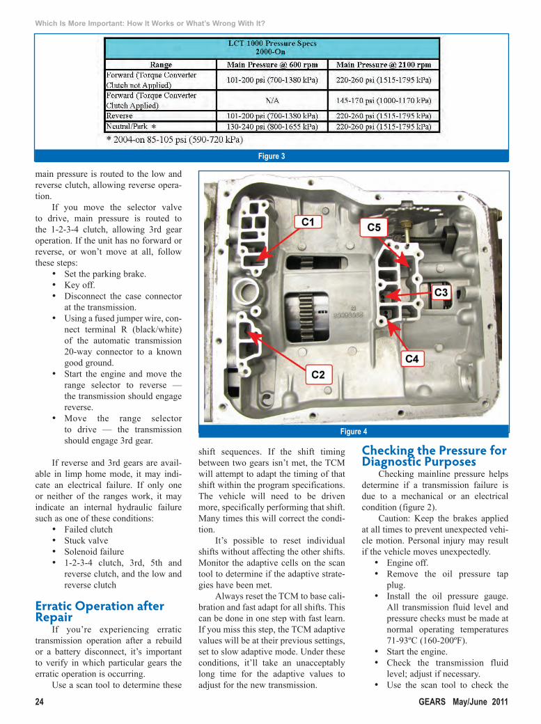
To verify whether a shift solenoid, shift valve, or clutch is at fault, swap shift solenoids C, D and E with one another. If the problem remains the same, look for a valve or clutch fault. If it changes, suspect the solenoid.
With the valve body removed, you can air check each clutch (figure 4).
Figure 5
A better way to test your light-duty automotive transmissions - Mustang’s Universal Transmission Dyno - Smarter by Design.
MEMBERSOLENOID TESTERSwww.mustangae.com
CALL 888-468-7826WIRELESS TRANSMISSION
CONTROL MODULESVALVE BODY
TESTERS

26 GEARS May/June 2011
Which Is More Important: How It Works or What’s Wrong With It?
Always service the spin-on oil fil-ter at regular intervals. Make sure the magnet is present at the top of the filter.
Always make sure the valve body bolts are tightened evenly to 84-110 in-lbs. A burnishing tool is available through the aftermarket to smooth out any irregular marks in the bore for the E shift valve. If the E shift valve sticks in its bore, it usually affects 4th gear and sets code P0872. After you clear the code, the vehicle will shift normally: 1-2-3.
Gear ratio error in 5th (P0735 2001-2005), or 6th (P0736 2006-on) before and after a rebuild can be caused by a damaged range fork in the transfer case, causing the transfer case to pop out of gear at freeway speeds (figures 5 and 6). Units affected are 2001-current K Series Chevy Silverado/GMC Sierra 2500HD/3500.
Four wheel drive vehicles equipped with Allison transmissions use the vehi-cle speed sensor on the transfer case as an output speed sensor. When the trans-fer case goes into neutral, the computer sees the input RPM change as vehicle speed remains constant, so it thinks the transmission is slipping. One of the main causes for this failure is a lack of lubrication due to low fluid level.
Over time, the pump assembly can wear a pinhole into the magnesium case and produce a small leak. GM has released an updated clip that resists wear from the pump into the case (figure 7). GM has also released an updated range fork and hub assembly to help with wear issues. Anaheim Gear of Anaheim, California recommends using GM Autotrak fluid for improved durability.
• Autotrak Fluid P/N 12378508• Range Fork P/N 12544310 (261
XHD) 12384964 (263 XHD)
We’ve also found the snap ring groove in the rear case half for the output bearing is wearing out (figure 8). The magnesium case is too soft and the axial movement of the output shaft causes the snap ring groove to widen as much as 0.0200”. This excess clear-ance causes the entire shaft to walk back and forth, resulting in range fork wear, which can cause the transmission to shift into neutral at freeway speeds.
Figure 6
Figure 7
Figure 8

Leave it to Corteco® to introduce a new, easy way to install lip seals and bonded pistons that prevents damaging the seal. Introducing the Lip Wizard™, available exclusively in TransTec® transmission kits.
This simple device installs lip seals and bonded pistons in almost any transmission. You no longer have to worry about tearing a lip seal or buying expensive installation tools that only work on specific transmissions. The Lip Wizard™ is flexible, versatile, reuseable and recyclable. Best of all, it’s absolutely free. You’ll find the new Lip Wizard™ installation tool inside virtually every TransTec® gasket and overhaul kit. Visit www.TransTec.com/LipWizard for more information.
A Division of Freudenberg-NOK T: 419.499.2502 • F: 419.499.2804 • Milan, OH
Every so often,
new technology comes along
that completely changes
the way we do things.
New_Pkg_LipWizard_ad_final.indd 1 1/25/11 11:31 AM

28 GEARS May/June 2011
Which Is More Important: How It Works or What’s Wrong With It?
LCT 1000 applications may exhibit late shifts, no shifts, or a lack of power. This may be caused by the PTO switch indicating that the PTO is being com-manded on. It may act very similar to a plugged fuel filter, and likely won’t set a DTC. The TCM is being commanded by the ECM to change the shift points for the transmission. The engine speed will typically be limited to 2000-3000 RPM (depending on calibration).
You can monitor the PTO switch with a scan tool on most applications. If the PTO switch is activated or if the switch has failed, the ECM will limit engine RPM at all throttle openings. In addition, you may notice that turbo boost pressure, MAF, and fuel delivery commands indicate the engine isn’t under full load.
When these conditions are met, the ECM will command the TCM to change the shift points, which can lead to the complaint. If the switch is
off, check the switch and wiring with your scan tool or multimeter. Repair or replace the switch as necessary. The PTO switch on the 2001-06 applica-tions is located right of center on the dash (figure 9).
Many customers are installing PTO switches in vehicles that weren’t originally equipped with a PTO from the factory. Customers are using the PTO input to force the engine to idle up to speed after the engine warm up.
The factory harness is in place up to connector C106, so the installation is fairly simple. PTO switch kits are avail-able from several sources. This means this condition may occur even though the vehicle isn’t equipped with a PTO.
LCT 1000 applications may exhib-it any of these conditions:
• Transmission won’t move for-ward or reverse (range inhib-ited).
• Possible electrically related
shift solenoid, temperature sen-sor, or PSM DTCs.
• Transmission will move for-ward and reverse but won’t shift.
These conditions may be intermit-tent.
Inspect the main transmission har-ness; it may be pinched where the frame rail meets the body (at the body mounts). If the harness is pinched, repair the wiring and reroute it to pre-vent it from becoming pinched again. This problem is common on crew cab applications.
Vehicles come and go. Knowing what it takes to fix them is like having the key to every room: all you have to do is turn the key.
Until next time, remember: Understanding how the transmission operates is just as important as under-standing why it’s acting up.
Figure 9

If it’s got wheels, chances are we have a transmission repair kit for it.A box, no, but that doesn’t mean we aren’t thinking outside of it.As a technological leader for over 30 years, we’re constantly striving toimprove ourselves and grow our product line to give you the world’slargest and most reliable selection of transmission repair kits.
Just about the only vehicle we don’t makea transmission repair kit for.
209-PRE-097 L: 7.375x10.125 T: 8.125x10.875 B: 8.375x11.125 4CGears Magazine..........May/June 2011
www.transmissionkits.com
14 Todd Court Extension, Yaphank, NY 11980(631) 567-2000 • Fax (631) 567-2640Toll Free: 800-872-6649Florida Office:6790 Hillsdale Point, Boynton Beach, FL 33437(561) 734-2332 • Fax (561) 734-2375E-mail: [email protected]
The Problem Solvers.
NEW Precision International K73900GX Overhaul Kit
JF011E applications. Banner and Master kits also available.
K73900GXOverhaul Kit
Quantity plus qualityFrom the latestmakes andmodels to the oldest and everything in between, we have asolution to virtually every transmission repair problem. They’re guaranteed towork, too.All are cross-checked against OEM specs. All changes are noted andmade. Andwe alwaysuseOE parts or better. Plus, with our huge inventory and state-of-the-art warehousingcapabilities, we’ll deliver exactly what you needwhen andwhere you need it.
Tech us outPrecision also offers outstanding technical assistance and support, including our“state-of-the-part”, interactive websitewww.transmissionkits.com. It puts a wealth ofvaluable information right at your fingertips such as continually updated video seminarsfrom leading transmission expert John Parmenter, question and answer forums,complete parts information andmuchmore.
So the next time you need a transmission repair kit, don’t get boxed into a corner.Draw fromPrecision International’s vast experience and product line. Formoreinformation, give us a call.
209PRE-7.375x10.125-097:Layout 1 4/19/11 1:43 PM Page 1