Embed Size (px)
Citation preview

Whirlpool Dispenser Cup
Michigan State University Senior Design
ECE 480, Team 8 Spring 2015
Project Sponsor
Whirlpool
Project Facilitator Dean Aslam
Team Members
Daniel Sun Gao Xin
HongYi Shen Connor Grossman Daniel Gomez

Table of Contents
1. Executive Summary 1. Background 2. Design Approach
2. Technical Summary 1. Customer Requirements 2. Microcontrollers 3. Power Supply 4. Sensors
3. Design Stages 1. 3D Model of the Dispenser Cup 2. Active Bandpass Filters
4. Fast Diagram 5. Project Management
1. Technical Responsibilities 2. NonTechnical Responsibilities 3. Gantt Chart
6. Budget 7. Conclusion/Recommendation 8. References 9. Appendix
1. Executive Summary 1. 1 Background
Whirlpool Corporation is one of the largest washing machine manufacturers. It’s
headquartered in Benton Charter which is a township in Michigan. The Company was
founded on November 11,1911. At the very beginning, it was a small company that
produced electric, motor driven, wringer washers. With the science and technology
developing rapidly, most families choose to use a washing machine at home instead of
doing laundry outside washing by hand or driving to the laundromat. So the rigid
demand of having a household washing machine increased rapidly. Whirlpool growing
fast and becoming one of Fortune 500 company,having an annual revenue of about
19 billion dollars. They have more than 70 manufacturing and technology research
centers in the world. However a the new problem also came up, which is how to use
the least energy to wash the cloth clean. Being energy efficient and to be
environmentally friendly are two big problems for the manufacturer. In addition, with
the fossil energy being scarce, the government and many environmental protection
organizations are pressing this issue. Energy Star is an international standard for
energy efficient consumer, it was created in 1992 by the Environmental Protection
Agency and the Department of Energy. It aims to encourage the manufacturer to
design the most energy efficient product. We can see the Energy Star label on most of
whirlpool products on the market.The label shows how much energy and money it can
save a customer every year. For the customer, they take this into their consideration

when they choose the product.. Now, many companies like whirlpool are willing to fund
the research to find a more economically feasible way to reduce energy cost.
1.2 Design Approach
The aim of this project is to prototype a completely functional, yet independant,
dispenser cup. The independence of this system means that no contact pads or
harnesses can be used in between the appliance and the dispenser cup. Our design will
not be streamlined into the market, but rather, it’s a proof of concept that the
requirements set by Whirlpool are feasible and can be used in future works relating to
our project.
By combining an LED and a photoresistor sensor we can detect when a liquid is
placed in one of the cups on the dispenser. Along with the sensors, there will be a
bandpass filter that is different for each cup sensor for increased accuracy and more
reliability. It is left up to the user to pour the correct contents into the specified cup or the
system will not work. In addition to the sensor, the system must provide its own power
since it must be independant from the appliance.
A solar cell on the outside face of the dispenser will always be exposed to the
environment and convert light in the surrounding area into energy used to charge a
battery, which in turn, powers the system. Another feature is to make the system
independant. This can be done by implementing wireless communication between the
appliance and the dispenser cup. Using a wireless transceiver, the appliance and
dispenser cup can communicate with each other without the use of contacts pads or
harnesses.
The last feature of the system, is user friendly LEDs to indicate which cups need
to be filled depending on what cycle the user selects. This ties into the concept of
wireless communication. The user will select a cycle the appliance will then wirelessly
communicate that cycle to the dispenser cup and from there the LEDs light up the
appropriate cups.
2. Technical Summary 2.1 Customer Requirements
The customer has a functional dispenser cup with content detection that uses
LEDs and sensors to detect which dispenser cup has a liquid or powder in it. From there
they wish to determine the actual substance based on which cup was filled. To make
the appliance lower cost and more efficient, the customer has asked us to implement
wireless communications between the appliance control unit and the dispenser. The
dispensers are mostly used in washing machine appliances which tend to vibrate a lot,
making wireless communication a key factor for the dispenser and appliance. Another
task is to implement LED’s to light up with certain cycles of the washing machine are
selected so the user knows which cup needs to be filled in order to perform that cycle.
Wireless power is another feature that must be implemented in the dispenser. All of this

is to make the dispenser physically independent from the appliance control unit so that
the dispenser can be removed and cleaned if needed. Overall there are three task we
need to accomplish:
1. To have the appliance control unit tell the dispenser which cups need to
be filled and have it tell the user via LEDs
2. To power the dispenser independently
3. Wireless communication between the appliance control unit and the
dispenser for future features of the system
2.2 Microcontrollers
The microcontroller that will be used for the initial and testing stage is the
EZ430RF2500. This microcontroller consists of two separable boards that connect
together when they are being programmed. Both boards are identical and can perform
the same task, so each board can act as a transceiver to send information between
each other. This microcontroller was selected for the testing phase because of its ease
of use and its wireless capabilities. One of the boards would be placed in the main
system while the other is placed in the dispenser cup, allowing for easy and reliable
communication between the two. However, one of the design goals is to keep costs to a
minimum, to reduce costs it would be necessary to change microcontrollers as the
EZ430RF2500 proves to be very expensive.
One way to reduce the cost is by using a cheaper microcontroller. A microcontroller that
meets this criteria is the MSP430G2553. The only problem with this microcontroller is
that it does not have the wireless transceiver to communicate with the main system.
Therefore the team has implemented a new transceiver, CC2500. This will implement
the wireless communication part of the system. The team will have to code the wireless
communication of the devices which is one of the disadvantages when compared to the
EZ430RF2500.
2.3 Power Supply
One of the main customer requirements is for the dispenser cup to be
selfpowered. As previously mentioned there must be no contact pads or cables
between the main system and the dispenser cup. One of the first solutions the team
came up with was to flow current through a coil in the main system, then this coil would
propagate an electromagnetic field than would be received by a coil placed in the
dispenser cup this would induced voltage onto the second coil and would wirelessly
power up the dispenser cup system without the need of contact pads or cables.
However, the more voltage that was needed in the second coil then the bigger the coils
would have to be. This proved to be as challenge, as the proposed circuitry needs a
decent amount of voltage and current. Another disadvantage is the distance that the
voltage can be transferred is really minimal, which may or may not be an issue in our
design. Instead of this idea, the team opted for a different method.
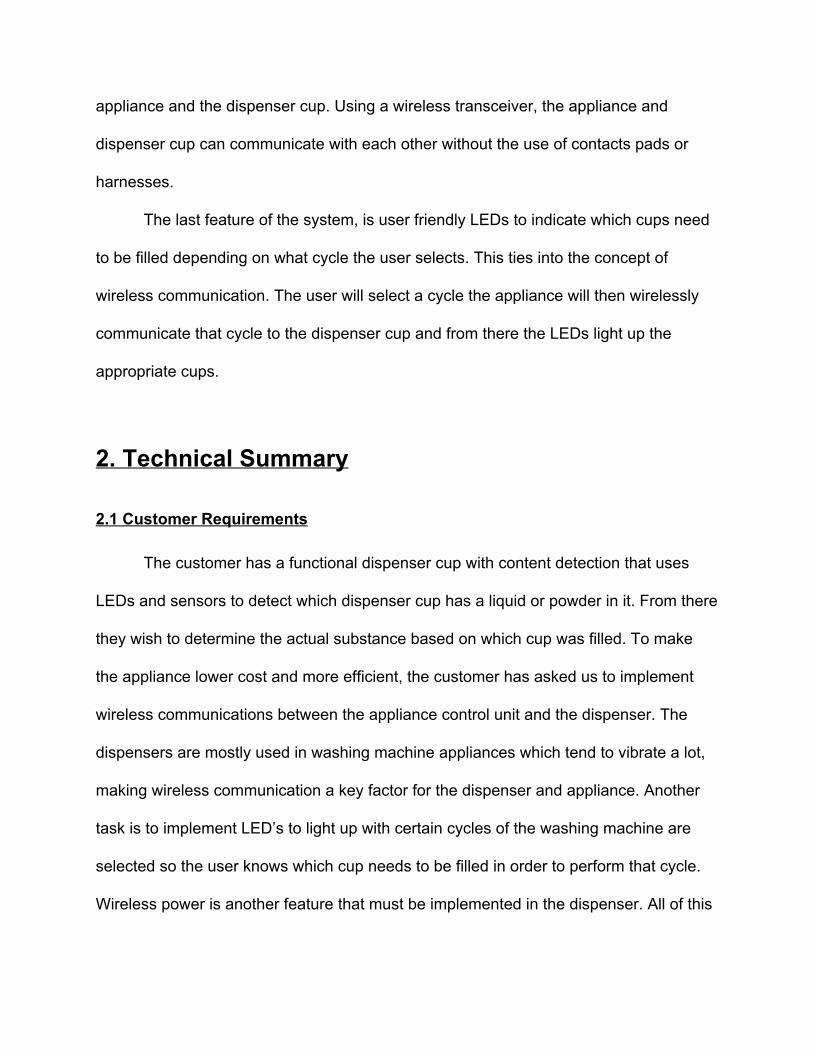
The next method will accomplished the task by using a solar cell, this solar cell
would not be the main supply or the system. It would be used to charge a battery that
would act as the voltage supplier for the rest of the circuit. Then the main voltage in the
supply would be stepped down to get the voltages that are necessary in the circuits

shown on (figure 231), these are the 3.3V to power the microcontroller and the voltage
divider and 5V to power the LED used in the sensor and 9V for the bank of LEDs that
would let the user know what cups to fill.
Figure 231
2.4 Sensors
The overall goal of our sensor system is to detect the contents that are placed
inside the cups. We plan on using a photoresistor and an LED to accomplish this. On
one side of the cup there will be an area for the LED to shine and the other side will
have an area for the photoresistor to be exposed to the light of the LED. Once the
photoresistor is exposed to the light the resistance changes. In darkness, the resistance
is really high and vice versa when exposed to bright light. With contents in the cup we
can measure the voltage across the resistor (figure 241) at that time, then use a
microcontroller to detect this voltage and tell the dispenser cup that there are contents
in it. This value will be different depending on the material thats is the cup.
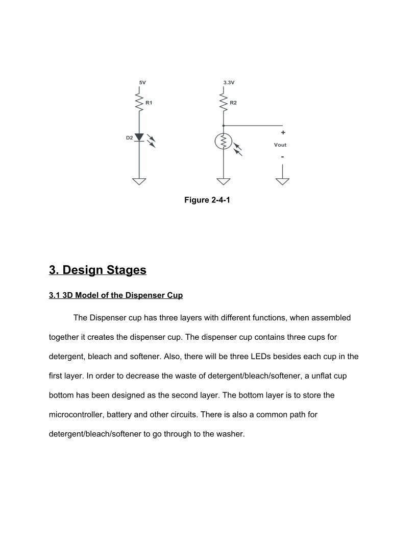
Figure 241
3. Design Stages 3.1 3D Model of the Dispenser Cup
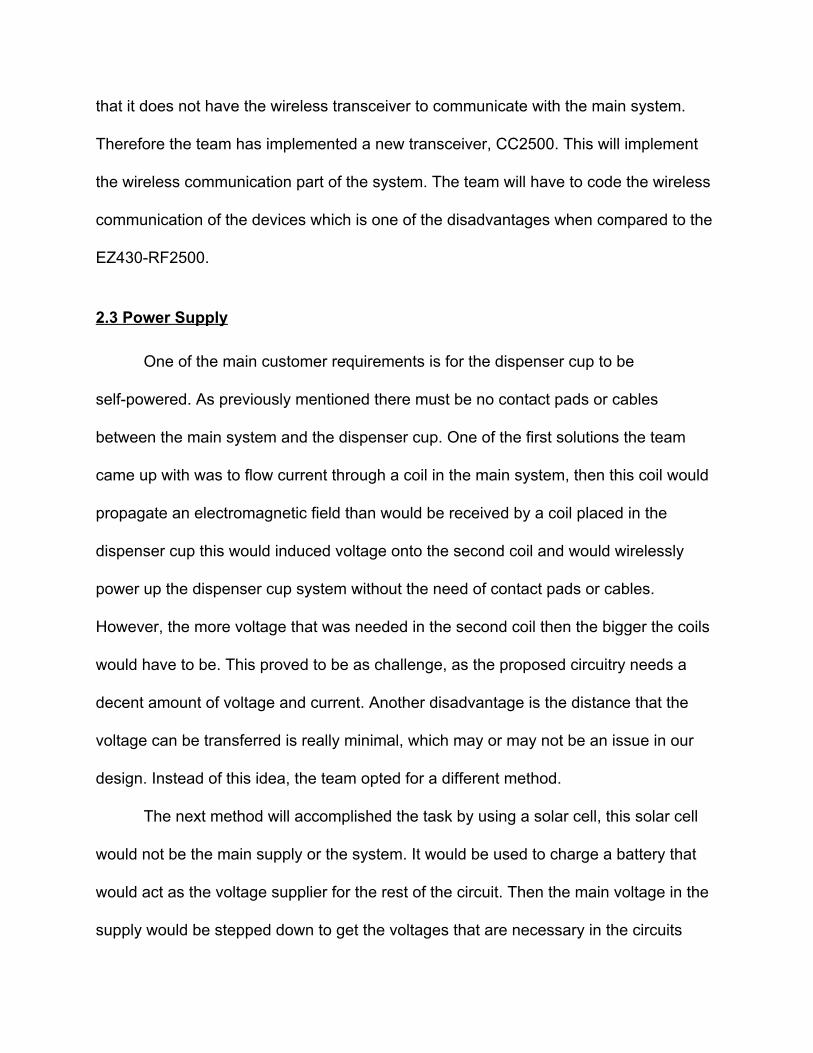
The Dispenser cup has three layers with different functions, when assembled
together it creates the dispenser cup. The dispenser cup contains three cups for
detergent, bleach and softener. Also, there will be three LEDs besides each cup in the
first layer. In order to decrease the waste of detergent/bleach/softener, a unflat cup
bottom has been designed as the second layer. The bottom layer is to store the
microcontroller, battery and other circuits. There is also a common path for
detergent/bleach/softener to go through to the washer.

Figure 3.11 First Layer

Figure 3.12 Second Layer Top
Figure 3.13 Second Layer Bottom
Figure 3.14 Bottom Layer Top
Figure 3.15 Bottom Layer Back

Figure 3.16 Assembled Dispenser Cup Top
Figure 3.17 Assembled Dispenser Cup Right

3.2 Active Bandpass Filter
An active bandpass filter is to be implemented with the sensors. The sensors in
our dispenser cup are used to detect when contents are pour into the cups. Are sensors
will be sensitive to light due to the photoresistor in the sensor design. This means that
ambient light from the environment around the dispenser cup will continuously be affect
the value of the photoresistors. To solve this problem we are going to integrate three
different bandpass filters (figure 321), one for each cup. This should make our sensors
less sensitive to ambient and overall make them more reliable.
The reason we need three different bandpass filter is due to the fact the each
liquid (detergent, bleach and fabric softener) will refract the light of the bright red led
differently, which yield a different wavelength/frequency for each liquid. After calculating
how each liquid changes the light we can start designing the filters. All a bandpass filter
is a high pass filter and a low pass filter in series. You first design the high pass filter to
take care of the low end of your frequency range. After choosing a low end frequency
(f1) and a value of C1 use equations 321, 322 & 323 to solve for all other unknown
values.
1 /( 1 f1)R = 1 √2 * π *C * Eq. 321 2 /(2 1 f1)R = 1 √2 * π *C * Eq. 322 1 2C = C Eq. 323
The next step is to design the low pass filter by picking the high end of the frequency range (f2), pick C1, and use equations 324 & 325.
2 1C = C * 2 Eq. 324 1 2 /(2 1 2)R = R = 1 √2 * π *C * f Eq. 325
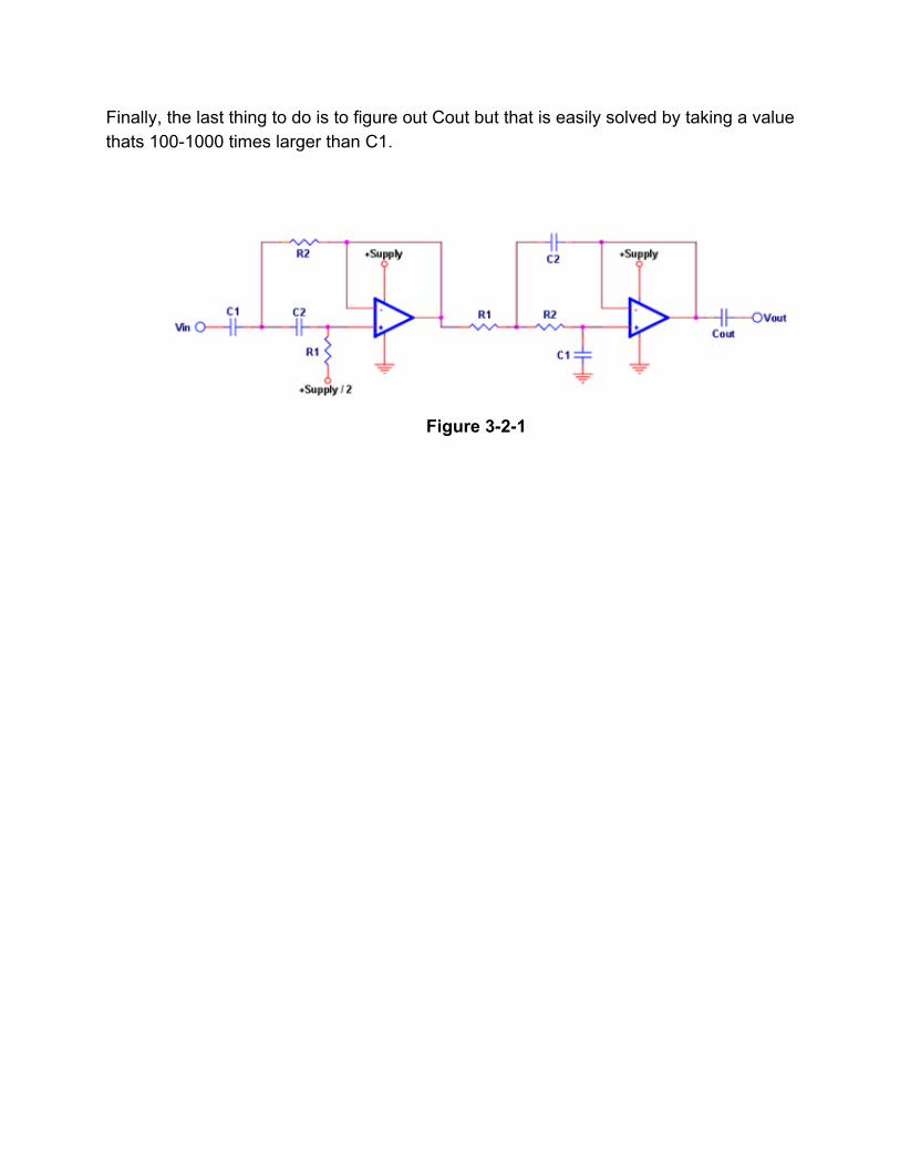
Finally, the last thing to do is to figure out Cout but that is easily solved by taking a value thats 1001000 times larger than C1.
Figure 321

4. Fast Diagram The following function analysis system technique (FAST) shows the relationships
between selecting a washing cycle to actually starting the cycle. Each box represent an
action that should have happened and each box before and after it are the actions
before and after.

5. Project Management 5.1 Technical Responsibilities
Name Responsibility 1 Responsibility 2 Responsibility 3
Selection of Parts and Ordering
Research Prototyping & Refinement
Daniel Sun Photoresistors Design Approaches Building/Testing Prototype
Connor Grossman RGB LEDS Active Bandpass Filter
Building/Testing Prototype
Daniel Gomez Microcontroller Power Supply/ Voltage Divider
Programming Microcontroller
Hong Yi Shen Rechargeable Battery
Background Material
Programming Microcontroller
Gao Xin Solar Cell Detergent/Softner/Bleach
Building/Testing Prototype
5.2 NonTechnical Responsibilities
Name Responsibility
Daniel Sun Project Manager
Connor Grossman Documentation Preparation
Daniel Gomez Lab Coordinator
Hong Yi Shen Presentation Manager
Gao Xin Project Webmaster

5.3 Gantt Chart
6. Budget
Parts Cost
20 piece of 50100k ohm photoresistors $4.22
9V Battery $9.65
Solar Cell $6.95
RGB LEDS $9.95
Microcontroller Varies
Detergent/Bleach/Softener $40~

3D Model printing Varies
Total Varies
7. Conclusion/Recommendation
The recommendation that has been provided is to use the EZ430RF2500
microcontroller through the testing stages along with our design. If cost need to be further reduced, Whirlpool will need to consider using the MSP430G2553 along with the CC2500 Transceivers.
8. References 9. Appendix