Embed Size (px)
Citation preview
THIS MANUAL MUST ACCOMPANY THE EQUIPMENT AT ALL TIMES.
To find the latest revision of this publication, visit our website at:
www.mqpower.com
®
WHISPERWATT™ SERIES
MODEL DCA25SSIU4F60Hz GENERATOR
(ISUZU 4LE2T DIESEL ENGINE)
PARTS LIST NO. M1871300104B
Revision #0 (05/14/15)
OPERATION AND PARTS MANUAL
PAGE 2 — DCA25SSIU4F 60 HZ GENERATOR • OPERATION AND PARTS MANUAL — REV. #0 (05/14/15)
PROPOSITION 65 WARNING
Diesel engine exhaust and some of
DCA25SSIU4F 60 HZ GENERATOR• OPERATION MANUAL — REV. #0 (05/14/15) — PAGE 3
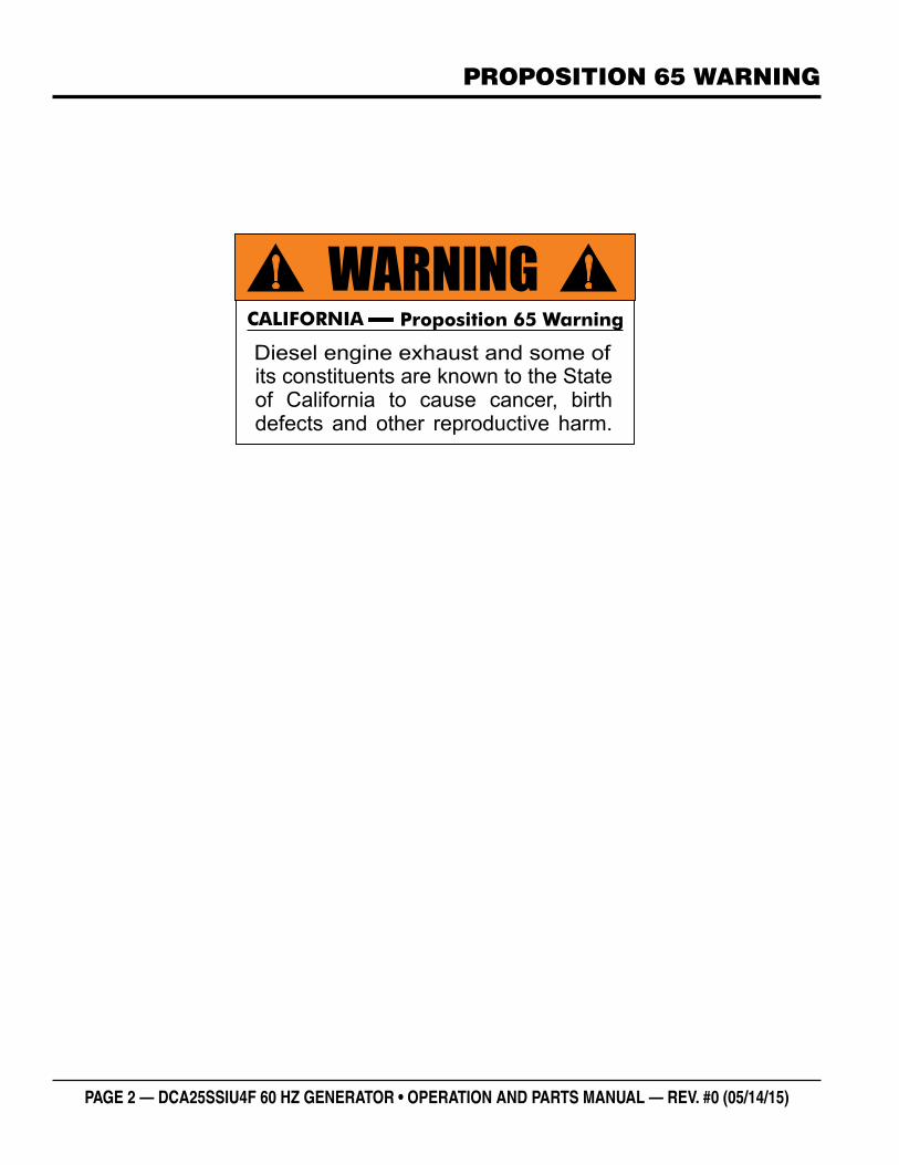
REPORTING SAFETY DEFECTS
If you believe that your vehicle has a defect that could cause a crash or could cause injury or death, you should immediately inform the National Highway Traffi c Safety Administration (NHTSA) in addition to notifying Multiquip Inc. at 1-800-421-1244.
If NHTSA receives similar complaints, it may open an investigation, and if it fi nds that a safety defect exists in a group of vehicles, it may order a recall and remedy campaign. However, NHTSA cannot become involved in individual problems between you, your dealer, or Multiquip Inc.
To contact NHTSA, you may either call the Vehicle Safety Hotline toll-free at 1-888-327-4236 (TTY: 1-800-424-9153), go to http://www.safercar.gov; or write to:
AdministratorNHTSA400 Seventh Street, SW.,Washington, DC 20590
You can also obtain information about motor vehicle safety from http://www.safercar.gov.
PAGE 4 — DCA25SSIU4F 60 HZ GENERATOR • OPERATION AND PARTS MANUAL — REV. #0 (05/14/15)
TABLE OF CONTENTS
DCA25SSIU4F 60 Hz GeneratorProposition 65 Warning ........................................... 2Reporting Safety Defects ......................................... 3Table Of Contents .................................................... 4Safety Information .............................................. 6-11Specifications ........................................................ 12Dimensions ............................................................ 13Installation ........................................................ 14-15General Information ............................................... 16Major Components ................................................ 17Engine/Generator Control Panel....................... 18-19Output Terminal Panel Familiarization .............. 20-22Load Application .................................................... 23Generator Outputs ............................................ 24-25Gauge Reading ..................................................... 25Output Terminal Panel Connections ................. 26-27Inspection/Setup ............................................... 28-31Generator Start-Up Procedure (Manual) .......... 32-33Generator Start-Up Procedure (Auto Mode) .......... 34Generator Shut-Down Procedures ........................ 35Maintenance ..................................................... 36-40Trailer Maintenance .......................................... 41-43Trailer Guidelines .............................................. 44-58Troubleshooting Diagnostic Lamp ........................ 60Troubleshooting Generator .................................. 61Troubleshooting Engine ................................... 62-63Generator Wiring Diagram ..................................... 64Engine Wiring Diagram .......................................... 65Controller Wiring Wiring Diagram .......................... 66Battery Charger Wiring Diagram ........................... 68Jacket Water Heater Wiring Diagram ..................... 69Explanation Of Code In Remarks Column............. 70Suggested Spare Parts ......................................... 71
Component Drawings Generator Assembly ......................................... 72-73Control Box 1 Assembly ................................... 74-77Control Box 2 Assembly ................................... 78-81Engine And Radiator Assembly ........................ 82-85Output Terminal Assembly ................................ 86-87Battery Assembly.............................................. 88-89Muffler Assembly .............................................. 90-91Fuel Tank Assembly .......................................... 92-93Enclosure Assembly ......................................... 94-97Rubber Seals Assembly ................................... 98-99Battery Charger Assembly (Option).............. 100-101Jacket Water Heater Assembly (Option) ....... 102-103Nameplate And Decals Assembly ................ 104-105
Terms And Conditions Of Sale — Parts .............. 106
NOTICE
Specifications and part numbers are subject to change without notice.
DCA25SSIU4F 60 HZ GENERATOR• OPERATION MANUAL — REV. #0 (05/14/15) — PAGE 5
NOTES
PAGE 6 — DCA25SSIU4F 60 HZ GENERATOR • OPERATION AND PARTS MANUAL — REV. #0 (05/14/15)
SAFETY INFORMATION
Do not operate or service the equipment before reading the entire manual. Safety precautions should be followed at all times when operating this equipment. Failure to read and understand the safety messages and operating instructions could result in injury to yourself and others.
SAFETY MESSAGES
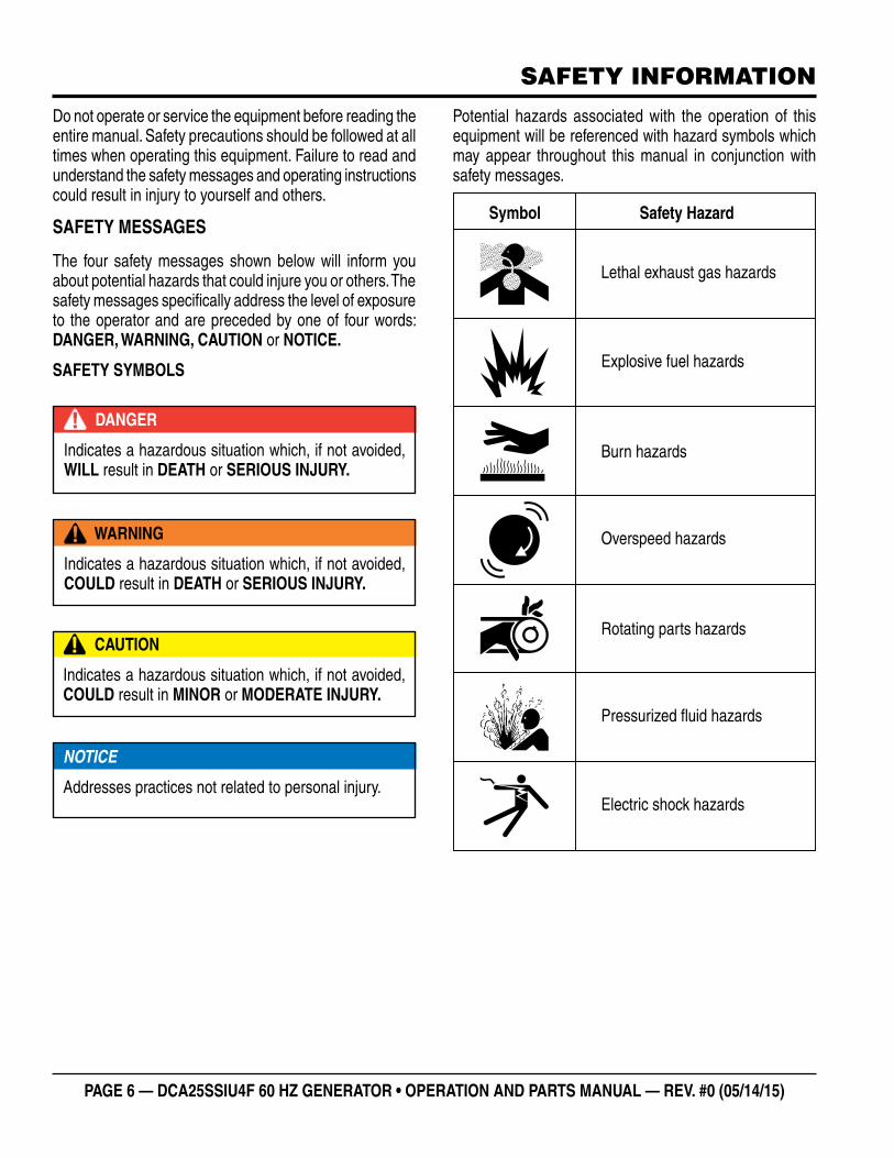
The four safety messages shown below will inform you about potential hazards that could injure you or others. The safety messages specifi cally address the level of exposure to the operator and are preceded by one of four words: DANGER, WARNING, CAUTION or NOTICE.
SAFETY SYMBOLS
DANGER
Indicates a hazardous situation which, if not avoided, WILL result in DEATH or SERIOUS INJURY.
WARNING
Indicates a hazardous situation which, if not avoided, COULD result in DEATH or SERIOUS INJURY.
CAUTION
Indicates a hazardous situation which, if not avoided, COULD result in MINOR or MODERATE INJURY.
NOTICE
Addresses practices not related to personal injury.
Potential hazards associated with the operation of this equipment will be referenced with hazard symbols which may appear throughout this manual in conjunction with safety messages.
DCA25SSIU4F 60 HZ GENERATOR• OPERATION MANUAL — REV. #0 (05/14/15) — PAGE 7
SAFETY INFORMATION
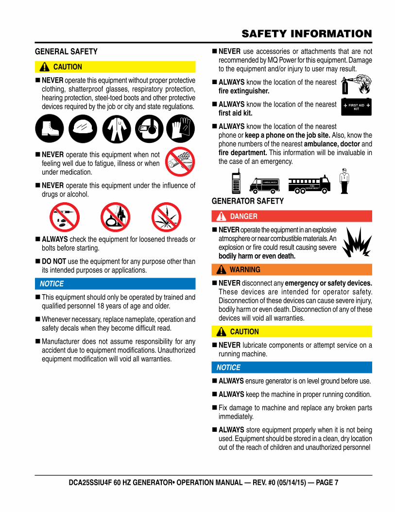
GENERAL SAFETY
CAUTION
�NEVER operate this equipment without proper protective clothing, shatterproof glasses, respiratory protection, hearing protection, steel-toed boots and other protective devices required by the job or city and state regulations.
�NEVER operate this equipment when not feeling well due to fatigue, illness or when under medication.
�NEVER operate this equipment under the infl uence of drugs or alcohol.
�ALWAYS check the equipment for loosened threads or bolts before starting.
�DO NOT use the equipment for any purpose other than its intended purposes or applications.
NOTICE
� This equipment should only be operated by trained and qualifi ed personnel 18 years of age and older.
�Whenever necessary, replace nameplate, operation and safety decals when they become diffi cult read.
�Manufacturer does not assume responsibility for any accident due to equipment modifi cations. Unauthorized equipment modifi cation will void all warranties.
�NEVER use accessories or attachments that are not recommended by MQ Power for this equipment. Damage to the equipment and/or injury to user may result.
�ALWAYS know the location of the nearest fi re extinguisher.
�ALWAYS know the location of the nearest fi rst aid kit.
�ALWAYS know the location of the nearest phone or keep a phone on the job site. Also, know the phone numbers of the nearest ambulance, doctor and fi re department. This information will be invaluable in the case of an emergency.
GENERATOR SAFETY
DANGER
�NEVER operate the equipment in an explosive atmosphere or near combustible materials. An explosion or fi re could result causing severe bodily harm or even death.
WARNING
�NEVER disconnect any emergency or safety devices. These devices are intended for operator safety. Disconnection of these devices can cause severe injury, bodily harm or even death. Disconnection of any of these devices will void all warranties.
CAUTION
�NEVER lubricate components or attempt service on a running machine.
NOTICE
�ALWAYS ensure generator is on level ground before use.
�ALWAYS keep the machine in proper running condition.
� Fix damage to machine and replace any broken parts immediately.
�ALWAYS store equipment properly when it is not being used. Equipment should be stored in a clean, dry location out of the reach of children and unauthorized personnel
PAGE 8 — DCA25SSIU4F 60 HZ GENERATOR • OPERATION AND PARTS MANUAL — REV. #0 (05/14/15)
SAFETY INFORMATION
ENGINE SAFETY
DANGER
� The engine fuel exhaust gases contain poisonous carbon monoxide. This gas is colorless and odorless, and can cause death if inhaled.
� The engine of this equipment requires an adequate free fl ow of cooling air. NEVER operate this equipment in any enclosed or narrow area where free fl ow of the air is restricted. If the air fl ow is restricted it will cause injury to people and property and serious damage to the equipment or engine.
WARNING
�DO NOT place hands or fingers inside engine compartment when engine is running.
�NEVER operate the engine with heat shields or guards removed.
�Keep fi ngers, hands hair and clothing away from all moving parts to prevent injury.
�DO NOT remove the radiator cap while the engine is hot. High pressure boiling water will gush out of the radiator and severely scald any persons in the general area of the generator.
�DO NOT remove the coolant drain plug while the engine is hot. Hot coolant will gush out of the coolant tank and severely scald any persons in the general area of the generator.
�DO NOT remove the engine oil drain plug while the engine is hot. Hot oil will gush out of the oil tank and severely scald any persons in the general area of the generator.
CAUTION
�NEVER touch the hot exhaust manifold, muffl er or cylinder. Allow these parts to cool before servicing equipment.
NOTICE
�NEVER run engine without an air fi lter or with a dirty air fi lter. Severe engine damage may occur. Service air fi lter frequently to prevent engine malfunction.
�NEVER tamper with the factory settings of the engine or engine governor. Damage to the engine or equipment can result if operating in speed ranges above the maximum allowable.
�Wet stacking is a common problem with diesel engines which are operated for extended periods with light or no load applied. When a diesel engine operates without suffi cient load (less than 40% of the rated output), it will not operate at its optimum temperature. This will allow unburned fuel to accumulate in the exhaust system, which can foul the fuel injectors, engine valves and exhaust system, including turbochargers, and reduce the operating performance.
In order for a diesel engine to operate at peak effi ciency, it must be able to provide fuel and air in the proper ratio and at a high enough engine temperature for the engine to completely burn all of the fuel.
Wet stacking does not usually cause any permanent damage and can be alleviated if additional load is applied to relieve the condition. It can reduce the system performance and increase maintenance. Applying an increasing load over a period of time until the excess fuel is burned off and the system capacity is reached usually can repair the condition. This can take several hours to burn off the accumulated unburned fuel.
�State Health Safety Codes and Public Resources Codes specify that in certain locations, spark arresters must be used on internal combustion engines that use hydrocarbon fuels. A spark arrester is a device designed to prevent accidental discharge of sparks or fl ames from the engine exhaust. Spark arresters are qualifi ed and rated by the United States Forest Service for this purpose. In order to comply with local laws regarding spark arresters, consult the engine distributor or the local Health and Safety Administrator.
DCA25SSIU4F 60 HZ GENERATOR• OPERATION MANUAL — REV. #0 (05/14/15) — PAGE 9
SAFETY INFORMATION
FUEL SAFETY
DANGER
�DO NOT start the engine near spilled fuel or combustible fl uids. Diesel fuel is extremely fl ammable and its vapors can cause an explosion if ignited.
�ALWAYS refuel in a well-ventilated area, away from sparks and open fl ames.
�ALWAYS use extreme caution when working with fl ammable liquids.
�DO NOT fi ll the fuel tank while the engine is running or hot.
�DO NOT overfi ll tank, since spilled fuel could ignite if it comes into contact with hot engine parts or sparks from the ignition system.
�Store fuel in appropriate containers, in well-ventilated areas and away from sparks and fl ames.
�NEVER use fuel as a cleaning agent.
�DO NOT smoke around or near the equipment. Fire or explosion could result from fuel vapors or if fuel is spilled on a hot engine.
TOWING SAFETY
CAUTION
�Check with your local county or state safety towing regulations, in addition to meeting Department of Transportation (DOT) Safety Towing Regulations, before towing your generator.
�Refer to MQ Power trailer manual for additional safety information.
� In order to reduce the possibility of an accident while transporting the generator on public roads, ALWAYS make sure the trailer that supports the generator and the towing vehicle are mechanically sound and in good operating condition.
� ALWAYS shutdown engine before transporting
�Make sure the hitch and coupling of the towing vehicle are rated equal to, or greater than the trailer “gross vehicle weight rating.”
�ALWAYS inspect the hitch and coupling for wear. NEVER tow a trailer with defective hitches, couplings, chains, etc.
�Check the tire air pressure on both towing vehicle and trailer. Trailer tires should be infl ated to 50 psi cold. Also check the tire tread wear on both vehicles.
�ALWAYS make sure the trailer is equipped with a safety chain.
�ALWAYS properly attach trailer’s safety chains to towing vehicle.
�ALWAYS make sure the vehicle and trailer directional, backup, brake and trailer lights are connected and working properly.
�DOT Requirements include the following:
• Connect and test electric brake operation.
• Secure portable power cables in cable tray with tie wraps.
� The maximum speed for highway towing is 55 MPH unless posted otherwise. Recommended off-road towing is not to exceed 15 MPH or less depending on type of terrain.
�Avoid sudden stops and starts. This can cause skidding, or jack-knifi ng. Smooth, gradual starts and stops will improve towing.
�Avoid sharp turns to prevent rolling.
� Trailer should be adjusted to a level position at all times when towing.
�Raise and lock trailer wheel stand in up position when towing.
�Place chock blocks underneath wheel to prevent rolling while parked.
�Place support blocks underneath the trailer’s bumper to prevent tipping while parked.
�Use the trailer’s swivel jack to adjust the trailer height to a level position while parked.
PAGE 10 — DCA25SSIU4F 60 HZ GENERATOR • OPERATION AND PARTS MANUAL — REV. #0 (05/14/15)
SAFETY INFORMATION
ELECTRICAL SAFETY
DANGER
�DO NOT touch output terminals during operation. Contact with output terminals during operation can cause electrocution, electrical shock or burn.
� The electrical voltage required to operate the generator can cause severe injury or even death through physical contact with live circuits. Turn generator and all circuit breakers OFF before performing maintenance on the generator or making contact with output terminals.
�NEVER insert any objects into the output receptacles during operation. This is extremely dangerous. The possibility exists of electrical shock, electrocution or death.
�Backfeed to a utility system can cause electrocution and/or property damage. NEVER connect the generator to a building’s electrical system without a transfer switch or other approved device. All installations should be performed by a licensed electrician in accordance with all applicable laws and electrical codes. Failure to do so could result in electrical shock or burn, causing serious injury or even death.
Power Cord/Cable Safety
DANGER
�NEVER let power cords or cables lay in water.
�NEVER stand in water while AC power from the generator is being transferred to a load.
�NEVER use damaged or worn cables or cords when connecting equipment to generator. Inspect for cuts in the insulation.
�NEVER grab or touch a live power cord or cable with wet hands. The possibility exists of electrical shock, electrocution or death.
�Make sure power cables are securely connected to the generator’s output receptacles. Incorrect connections may cause electrical shock and damage to the generator.
NOTICE
�ALWAYS make certain that proper power or extension cord has been selected for the job. See Cable Selection Chart in this manual.
Grounding Safety
DANGER
�ALWAYS make sure that electrical circuits are properly grounded to a suitable earth ground (ground rod) per the National Electrical Code (NEC) and local codes before operating generator. Severe injury or death by electrocution can result from operating an ungrounded generator.
�NEVER use gas piping as an electrical ground.
BATTERY SAFETY
DANGER
�DO NOT drop the battery. There is a possibility that the battery will explode.
�DO NOT expose the battery to open fl ames, sparks, cigarettes, etc. The battery contains combustible gases and liquids. If these gases and liquids come into contact with a fl ame or spark, an explosion could occur.
WARNING
�ALWAYS wear safety glasses when handling the battery to avoid eye irritation. The battery contains acids that can cause injury to the eyes and skin.
�Use well-insulated gloves when picking up the battery.
�ALWAYS keep the battery charged. If the battery is not charged, combustible gas will build up.
�ALWAYS recharge the battery in a well-ventilated environment to avoid the risk of a dangerous concentration of combustible gasses.
DCA25SSIU4F 60 HZ GENERATOR• OPERATION MANUAL — REV. #0 (05/14/15) — PAGE 11
SAFETY INFORMATION
� If the battery liquid (dilute sulfuric acid) comes into contact with clothing or skin, rinse skin or clothing immediately with plenty of water.
� If the battery liquid (dilute sulfuric acid) comes into contact with eyes, rinse eyes immediately with plenty of water and contact the nearest doctor or hospital to seek medical attention.
CAUTION
�ALWAYS disconnect the NEGATIVE battery terminal before performing service on the generator.
�ALWAYS keep battery cables in good working condition. Repair or replace all worn cables.
ENVIRONMENTAL SAFETY/DECOMMISSIONING
NOTICE
Decommissioning is a controlled process used to safely retire a piece of equipment that is no longer serviceable. If the equipment poses an unacceptable and unrepairable safety risk due to wear or damage or is no longer cost effective to maintain (beyond life-cycle reliability) and is to be decommissioned (demolition and dismantlement),be sure to follow rules below.
�DO NOT pour waste or oil directly onto the ground, down a drain or into any water source.
�Contact your country's Department of Public Works or recycling agency in your area and arrange for proper disposal of any electrical components, waste or oil associated with this equipment.
�When the life cycle of this equipment is over, remove battery and bring to appropriate facility for lead reclamation. Use safety precautions when handling batteries that contain sulfuric acid.
�When the life cycle of this equipment is over, it is recommended that the trowel frame and all other metal parts be sent to a recycling center.
Metal recycling involves the collection of metal from discarded products and its transformation into raw materials to use in manufacturing a new product.
Recyclers and manufacturers alike promote the process of recycling metal. Using a metal recycling center promotes energy cost savings.
EMISSIONS INFORMATION
NOTICE
The diesel engine used in this equipment has been designed to reduce harmful levels of carbon monoxide (CO), hydrocarbons (HC) and nitrogen oxides (NOx) contained in diesel exhaust emissions.
This engine has been certifi ed to meet US EPA Evaporative emissions requirements in the installed confi guration.
Attempting to modify or make adjustments to the engine emission system by unauthorized personnel without proper training could damage the equipment or create an unsafe condition.
Additionally, modifying the fuel system may adversely affect evaporative emissions, resulting in fi nes or other penalties.
Emission Control Label
The emission control label is an integral part of the emission system and is strictly controlled by regulations.
The label must remain with the engine for its entire life.
If a replacement emission label is needed, please contact your authorized engine distributor.
PAGE 12 — DCA25SSIU4F 60 HZ GENERATOR • OPERATION AND PARTS MANUAL — REV. #0 (05/14/15)
SPECIFICATIONS
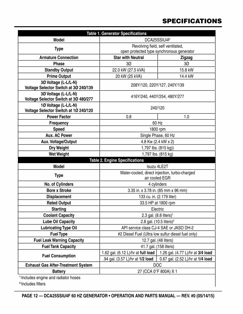
Table 1. Generator SpecificationsModel DCA25SSIU4F
Type Revolving field, self ventilated, open protected type synchronous generator
Armature Connection Star with Neutral ZigzagPhase 3Ø 3Ø
Standby Output 22.0 kW (27.5 kVA) 15.8 kWPrime Output 20 kW (25 kVA) 14.4 kW
3Ø Voltage (L-L/L-N) Voltage Selector Switch at 3Ø 240/139 208Y/120, 220Y/127, 240Y/139
3Ø Voltage (L-L/L-N) Voltage Selector Switch at 3Ø 480/277 416Y/240, 440Y/254, 480Y/277
1Ø Voltage (L-L/L-N) Voltage Selector Switch at 1Ø 240/120 240/120
Power Factor 0.8 1.0Frequency 60 Hz
Speed 1800 rpmAux. AC Power Single Phase, 60 Hz
Aux. Voltage/Output 4.8 Kw (2.4 kW x 2) Dry Weight 1,797 lbs. (815 kg))Wet Weight 1,797 lbs. (815 kg)
Table 2. Engine SpecificationsModel Isuzu 4LE2T
Type Water-cooled, direct injection, turbo-charged air cooled EGR
No. of Cylinders 4 cylindersBore x Stroke 3.35 in. x 3.78 in. (85 mm x 96 mm)Displacement 133 cu. in. (2.179 liter)Rated Output 33.5 HP at 1800 rpm
Starting Electric Coolant Capacity 2.3 gal. (8.8 liters)1
Lube Oil Capacity 2.8 gal. (10.5 liters)2 Lubricating Type Oil API service class CJ-4 SAE or JASO DH-2
Fuel Type #2 Diesel Fuel (Ultra low sulfur diesel fuel only)Fuel Leak Warning Capacity 12.7 gal. (48 liters)
Fuel Tank Capacity 41.7 gal. (158 liters)
Fuel Consumption1.62 gal. (6.12 L)/hr at full load 1.26 gal. (4.77 L)/hr at 3/4 load.94 gal. (3.57 L)/hr at 1/2 load 0.67 gal. (2.52 L)/hr at 1/4 load
Exhaust Gas After-Treatment System DOCBattery 27 (CCA 0°F 800A) X 1
1 Includes engine and radiator hoses2 Includes filters
DCA25SSIU4F 60 HZ GENERATOR• OPERATION MANUAL — REV. #0 (05/14/15) — PAGE 13
DIMENSIONS
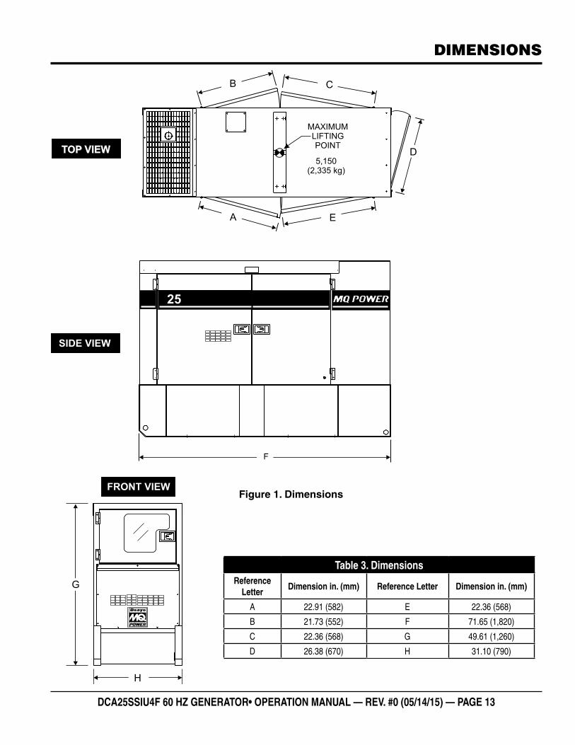
25
5,150(2,335 kg)
Table 3. DimensionsReference
LetterDimension in. (mm) Reference Letter Dimension in. (mm)
A 22.91 (582) E 22.36 (568)
B 21.73 (552) F 71.65 (1,820)
C 22.36 (568) G 49.61 (1,260)
D 26.38 (670) H 31.10 (790)
Figure 1. Dimensions
PAGE 14 — DCA25SSIU4F 60 HZ GENERATOR • OPERATION AND PARTS MANUAL — REV. #0 (05/14/15)
INSTALLATION
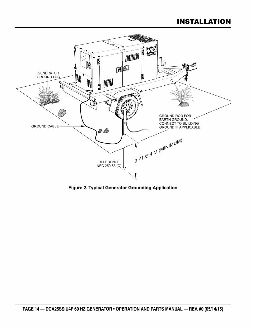
GENERATORGROUND LUG
GROUND CABLE
REFERENCENEC 250-83 (C)
GROUND ROD FOR EARTH GROUND.CONNECT TO BUILDINGGROUND IF APPLICABLE
8 FT./2.4 M (MINIMUM)
Figure 2. Typical Generator Grounding Application
DCA25SSIU4F 60 HZ GENERATOR• OPERATION MANUAL — REV. #0 (05/14/15) — PAGE 15
INSTALLATION
OUTDOOR INSTALLATION
Install the generator in a area that is free of debris, bystanders, and overhead obstructions. Make sure the generator is on secure level ground so that it cannot slide or shift around. Also install the generator in a manner so that the exhaust will not be discharged in the direction of nearby homes.
The installation site must be relatively free from moisture and dust. All electrical equipment should be protected from excessive moisture. Failure to do will result in deterioration of the insulation and will result in short circuits and grounding.
Foreign materials such as dust, sand, lint and abrasive materials have a tendency to cause excessive wear to engine and alternator parts.
INDOOR INSTALLATION
Exhaust gases from diesel engines are extremely poisonous. Whenever an engine is installed indoors the exhaust fumes must be vented to the outside. The engine should be installed at least two feet from any outside wall. Using an exhaust pipe which is too long or too small can cause excessive back pressure which will cause the engine to heat excessively and possibly burn the valves.
MOUNTING
The generator must be mounted on a solid foundation (such as concrete) and set firmly on the foundation to isolate vibration of the generator when it is running. The generator must set at least 6 inches above the floor or grade level (in accordance to NFPA 110, Chapter 5-4.1). DO NOT remove the metal skids on the bottom of the generator. They are to resist damage to the bottom of the generator and to maintain alignment.
CAUTION
Pay close attention to ventilation when operating the generator inside tunnels and caves. The engine exhaust contains noxious elements. Engine exhaust must be routed to a ventilated area.
GENERATOR GROUNDING
To guard against electrical shock and possible damage to the equipment, it is important to provide a good EARTH ground (Figure 2).
Article 250 (Grounding) of the National Electrical Code (NEC) provides guide lines for proper grounding and specifies that the cable ground shall be connected to the grounding system of the building as close to the point of cable entry as practical.
NEC articles 250-64(b) and 250-66 set the following grounding requirements:
1. Use one of the following wire types to connect the generator to earth ground.
a. Copper - 8 AWG (5.3 mm2)
b. Aluminum - 6 AWG (8.4 mm2)
2. When grounding the generator (Figure 2) connect the ground cable between the lock washer and the nut on the generator and tighten the nut fully. Connect the other end of the ground cable to earth ground.
3. NEC article 250-52(c) specifies that the earth ground rod should be buried a minimum of 8 ft. into the ground.
NOTICE
When connecting the generator to any buildings electrical system ALWAYS consult with a licensed electrician.
NOTICE
This generator has a permanent bonding conductor between the generator stator windings and the frame.
PAGE 16 — DCA25SSIU4F 60 HZ GENERATOR • OPERATION AND PARTS MANUAL — REV. #0 (05/14/15)
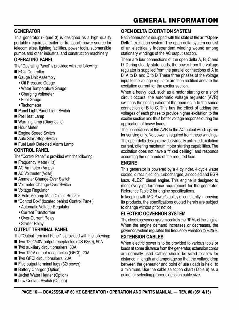
GENERATORThis generator (Figure 3) is designed as a high quality portable (requires a trailer for transport) power source for telecom sites, lighting facilities, power tools, submersible pumps and other industrial and construction machinery.OPERATING PANELThe “Operating Panel” is provided with the following:
�ECU Controller �Gauge Unit Assembly• Oil Pressure Gauge• Water Temperature Gauge• Charging Voltmeter• Fuel Gauge• Tachometer
�Panel Light/Panel Light Switch �Pre Heat Lamp �Warning lamp (Diagnostic) �Hour Meter �Engine Speed Switch �Auto Start/Stop Switch � Fuel Leak Detected Alarm Lamp
CONTROL PANELThe “Control Panel” is provided with the following:
� Frequency Meter (Hz) �AC Ammeter (Amps) �AC Voltmeter (Volts) �Ammeter Change-Over Switch �Voltmeter Change-Over Switch �Voltage Regulator � 3-Pole, 60 amp Main Circuit Breaker � “Control Box” (located behind Control Panel)• Automatic Voltage Regulator• Current Transformer• Over-Current Relay• Starter Relay
OUTPUT TERMINAL PANELThe “Output Terminal Panel” is provided with the following:
� Two 120/240V output receptacles (CS-6369), 50A � Two auxiliary circuit breakers, 50A � Two 120V output receptacles (GFCI), 20A � Two GFCI circuit breakers, 20A � Five output terminal lugs (3Ø power) �Battery Charger (Option) � Jacket Water Heater (Option) � Low Coolant Switch (Option)
OPEN DELTA EXCITATION SYSTEMEach generator is equipped with the state of the art “Open-Delta” excitation system. The open delta system consist of an electrically independent winding wound among stationary windings of the AC output section.There are four connections of the open delta A, B, C and D. During steady state loads, the power from the voltage regulator is supplied from the parallel connections of A to B, A to D, and C to D. These three phases of the voltage input to the voltage regulator are then rectified and are the excitation current for the exciter section. When a heavy load, such as a motor starting or a short circuit occurs, the automatic voltage regulator (AVR) switches the configuration of the open delta to the series connection of B to C. This has the effect of adding the voltages of each phase to provide higher excitation to the exciter section and thus better voltage response during the application of heavy loads. The connections of the AVR to the AC output windings are for sensing only. No power is required from these windings.The open-delta design provides virtually unlimited excitation current, offering maximum motor starting capabilities. The excitation does not have a “fixed ceiling” and responds according the demands of the required load.ENGINEThis generator is powered by a 4 cylinder, 4-cycle water cooled, direct injection, turbocharged, air cooled and EGR Isuzu 4LE2T diesel engine. This engine is designed to meet every performance requirement for the generator. Reference Table 2 for engine specifications. In keeping with MQ Power’s policy of constantly improving its products, the specifications quoted herein are subject to change without prior notice.ELECTRIC GOVERNOR SYSTEMThe electric governor system controls the RPMs of the engine. When the engine demand increases or decreases, the governor system regulates the frequency variation to ±.25%. EXTENSION CABLESWhen electric power is to be provided to various tools or loads at some distance from the generator, extension cords are normally used. Cables should be sized to allow for distance in length and amperage so that the voltage drop between the generator and point of use (load) is held to a minimum. Use the cable selection chart (Table 6) as a guide for selecting proper extension cable size.
GENERAL INFORMATION
DCA25SSIU4F 60 HZ GENERATOR• OPERATION MANUAL — REV. #0 (05/14/15) — PAGE 17
MAJOR COMPONENTS
Low Oil Pressre
High temp.
Over Crank
Over Speed
Engine Started
ECU Intergrated Gauge Control
R
25
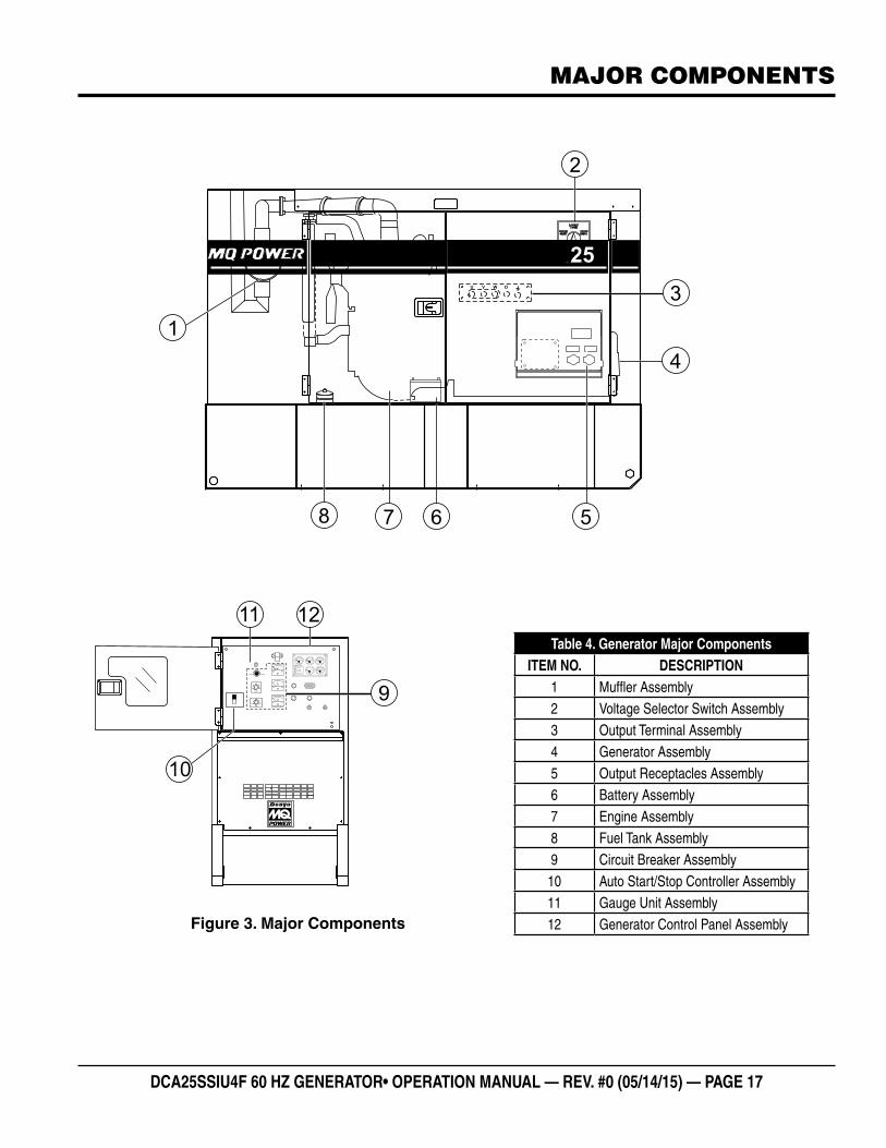
Table 4. Generator Major ComponentsITEM NO. DESCRIPTION
1 Muffler Assembly2 Voltage Selector Switch Assembly3 Output Terminal Assembly4 Generator Assembly5 Output Receptacles Assembly6 Battery Assembly7 Engine Assembly8 Fuel Tank Assembly9 Circuit Breaker Assembly
10 Auto Start/Stop Controller Assembly11 Gauge Unit Assembly12 Generator Control Panel AssemblyFigure 3. Major Components
PAGE 18 — DCA25SSIU4F 60 HZ GENERATOR • OPERATION AND PARTS MANUAL — REV. #0 (05/14/15)
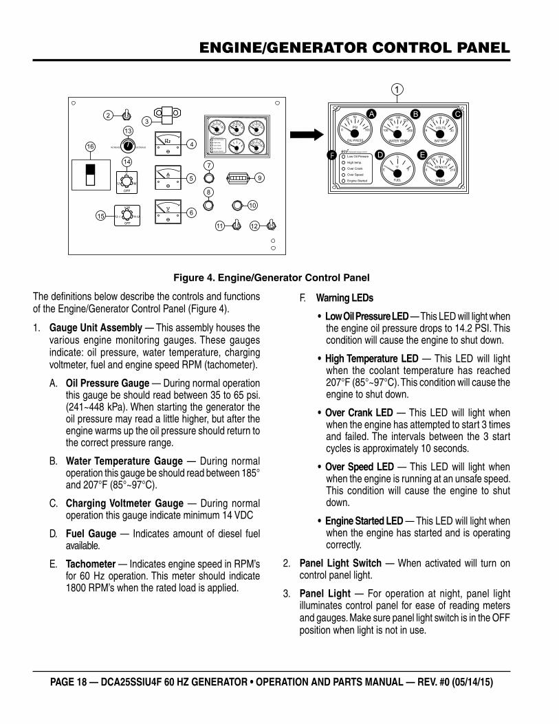
The definitions below describe the controls and functions of the Engine/Generator Control Panel (Figure 4).
1. Gauge Unit Assembly — This assembly houses the various engine monitoring gauges. These gauges indicate: oil pressure, water temperature, charging voltmeter, fuel and engine speed RPM (tachometer).
A. Oil Pressure Gauge — During normal operation this gauge be should read between 35 to 65 psi. (241~448 kPa). When starting the generator the oil pressure may read a little higher, but after the engine warms up the oil pressure should return to the correct pressure range.
B. Water Temperature Gauge — During normal operation this gauge be should read between 185° and 207°F (85°~97°C).
C. Charging Voltmeter Gauge — During normal operation this gauge indicate minimum 14 VDC
D. Fuel Gauge — Indicates amount of diesel fuel available.
E. Tachometer — Indicates engine speed in RPM’s for 60 Hz operation. This meter should indicate 1800 RPM’s when the rated load is applied.
Figure 4. Engine/Generator Control Panel
Low Oil Pressre
High temp.
Over Crank
Over Speed
Engine Started
ECU Intergrated Gauge Control
R
Low Oil Pressre
High temp.
Over Crank
Over Speed
Engine Started
ECU Intergrated Gauge Control
R
23
4
5
6
9
7
8
10
11 12
16
15
14
13
F
F. Warning LEDs
• Low Oil Pressure LED — This LED will light when the engine oil pressure drops to 14.2 PSI. This condition will cause the engine to shut down.
• High Temperature LED — This LED will light when the coolant temperature has reached 207°F (85°~97°C). This condition will cause the engine to shut down.
• Over Crank LED — This LED will light when when the engine has attempted to start 3 times and failed. The intervals between the 3 start cycles is approximately 10 seconds.
• Over Speed LED — This LED will light when when the engine is running at an unsafe speed. This condition will cause the engine to shut down.
• Engine Started LED — This LED will light when when the engine has started and is operating correctly.
2. Panel Light Switch — When activated will turn on control panel light.
3. Panel Light — For operation at night, panel light illuminates control panel for ease of reading meters and gauges. Make sure panel light switch is in the OFF position when light is not in use.
ENGINE/GENERATOR CONTROL PANEL
DCA25SSIU4F 60 HZ GENERATOR• OPERATION MANUAL — REV. #0 (05/14/15) — PAGE 19
ENGINE/GENERATOR CONTROL PANEL
4. Frequency Meter — Indicates the output frequency in hertz (Hz). Normally 60 Hz
5. AC Ammeter — Indicates the amount of current the load is drawing from the generator per leg selected by the ammeter phase-selector switch.
6. AC Voltmeter — Indicates the output voltage present at the U,V, and W Output Terminal Lugs.
7. Fuel Leak Detected Alarm Lamp — This lamp when ON indicates that fluids in the containment area have reach a high level.
8. Warning Lamp — This lamp turns ON when an engine fault/failure has occured, Reference Troubleshooting Diagnostic Lamp section in this manual for fault code details.
9. Hour Meter — Indicates the operational hours of the generator.
10. Pre-Heat Lamp — When the Auto Start/Stop Switch is placed in the manual position, this lamp will illuminate to indicate preheating of the engine glow plugs. When the lamp turns off, this indicates that the preheat cycle is complete and the engine can be started.
11. Auto Start-Stop Switch — This switch selects either manual or automatic operation . Center position is OFF (reset).
12. Engine Speed Switch — This switch controls the speed of the engine low or high.
13. Voltage Regulator Control — Allows ±15% manual adjustment of the generator’s output voltage.
14. Ammeter Change-Over Switch — This switch allows the AC ammeter to indicate the current flowing to the load connected to any phase of the output terminals, or to be switched off. This switch does not effect the generator output in any fashion, it is for current reading only.
15. Voltmeter Change-Over Switch — This switch allows the AC voltmeter to indicate phase to phase voltage between any two phases of the output terminals or to be switched off.
16. Main Circuit Breaker — This three-pole, 60 amp main breaker is provided to protect the U,V, and W Output Terminal Lugs from overload.
PAGE 20 — DCA25SSIU4F 60 HZ GENERATOR • OPERATION AND PARTS MANUAL — REV. #0 (05/14/15)
OUTPUT TERMINAL PANEL FAMILIARIZATION
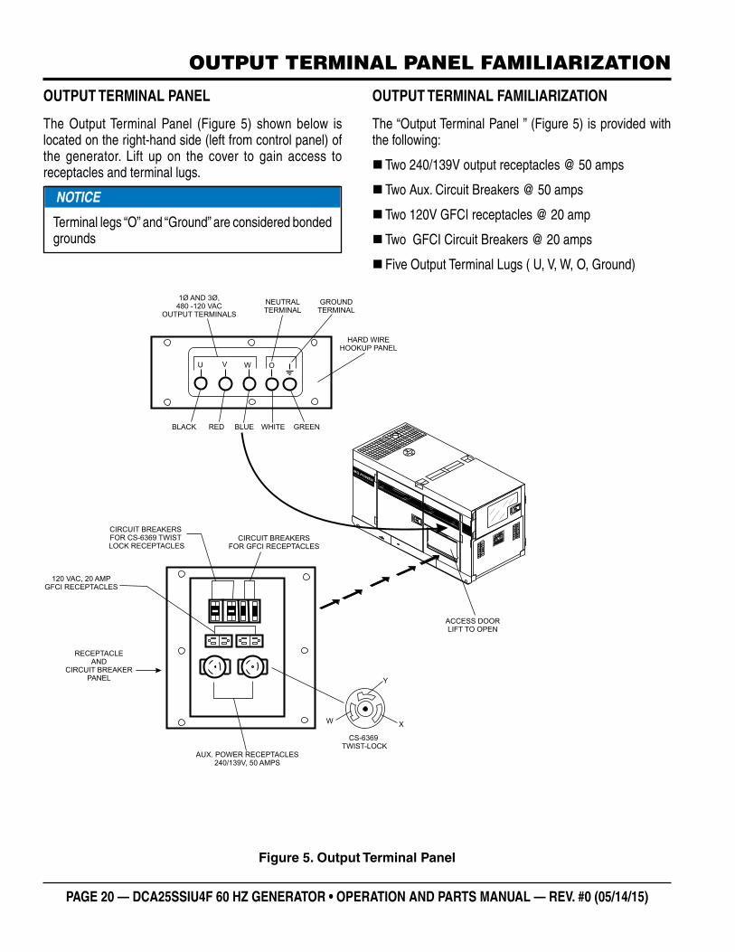
OUTPUT TERMINAL PANEL
The Output Terminal Panel (Figure 5) shown below is located on the right-hand side (left from control panel) of the generator. Lift up on the cover to gain access to receptacles and terminal lugs.
NOTICE
Terminal legs “O” and “Ground” are considered bonded grounds
OUTPUT TERMINAL FAMILIARIZATION
The “Output Terminal Panel ” (Figure 5) is provided with the following:
� Two 240/139V output receptacles @ 50 amps
� Two Aux. Circuit Breakers @ 50 amps
� Two 120V GFCI receptacles @ 20 amp
� Two GFCI Circuit Breakers @ 20 amps
� Five Output Terminal Lugs ( U, V, W, O, Ground)
AUX. POWER RECEPTACLES240/139V, 50 AMPS
120 VAC, 20 AMPGFCI RECEPTACLES
Y
XW
CS-6369TWIST-LOCK
CIRCUIT BREAKERSFOR GFCI RECEPTACLES
RECEPTACLEAND
CIRCUIT BREAKERPANEL
MQ
POW
ER
ACCESS DOORLIFT TO OPEN
HARD WIREHOOKUP PANEL
OU V W
BLACK RED BLUE WHITE GREEN
1Ø AND 3Ø,480 -120 VAC
OUTPUT TERMINALS
NEUTRALTERMINAL
GROUNDTERMINAL
CIRCUIT BREAKERSFOR CS-6369 TWISTLOCK RECEPTACLES
Figure 5. Output Terminal Panel
DCA25SSIU4F 60 HZ GENERATOR• OPERATION MANUAL — REV. #0 (05/14/15) — PAGE 21
OUTPUT TERMINAL PANEL FAMILIARIZATION
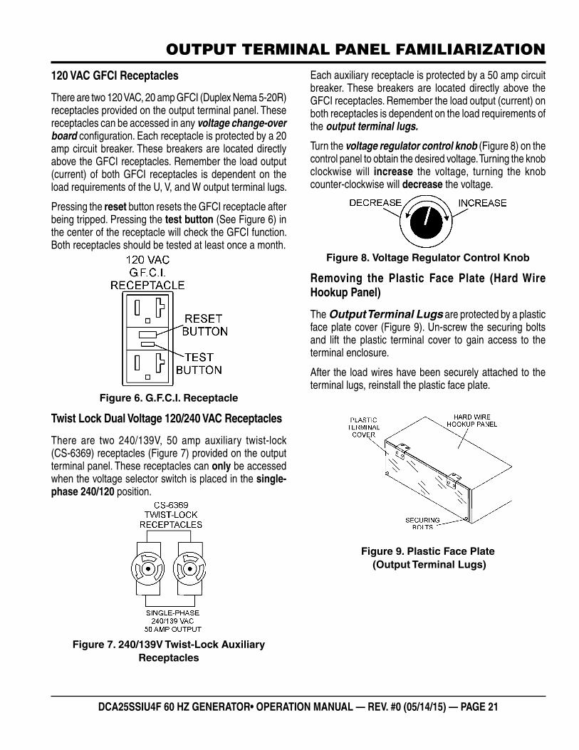
120 VAC GFCI Receptacles
There are two 120 VAC, 20 amp GFCI (Duplex Nema 5-20R) receptacles provided on the output terminal panel. These receptacles can be accessed in any voltage change-over board configuration. Each receptacle is protected by a 20 amp circuit breaker. These breakers are located directly above the GFCI receptacles. Remember the load output (current) of both GFCI receptacles is dependent on the load requirements of the U, V, and W output terminal lugs.
Pressing the reset button resets the GFCI receptacle after being tripped. Pressing the test button (See Figure 6) in the center of the receptacle will check the GFCI function. Both receptacles should be tested at least once a month.
Figure 6. G.F.C.I. Receptacle
Twist Lock Dual Voltage 120/240 VAC Receptacles
There are two 240/139V, 50 amp auxiliary twist-lock (CS-6369) receptacles (Figure 7) provided on the output terminal panel. These receptacles can only be accessed when the voltage selector switch is placed in the single-phase 240/120 position.
Figure 7. 240/139V Twist-Lock Auxiliary Receptacles
Each auxiliary receptacle is protected by a 50 amp circuit breaker. These breakers are located directly above the GFCI receptacles. Remember the load output (current) on both receptacles is dependent on the load requirements of the output terminal lugs.
Turn the voltage regulator control knob (Figure 8) on the control panel to obtain the desired voltage. Turning the knob clockwise will increase the voltage, turning the knob counter-clockwise will decrease the voltage.
Figure 8. Voltage Regulator Control Knob
Removing the Plastic Face Plate (Hard Wire Hookup Panel)
The Output Terminal Lugs are protected by a plastic face plate cover (Figure 9). Un-screw the securing bolts and lift the plastic terminal cover to gain access to the terminal enclosure.
After the load wires have been securely attached to the terminal lugs, reinstall the plastic face plate.
Figure 9. Plastic Face Plate (Output Terminal Lugs)
PAGE 22 — DCA25SSIU4F 60 HZ GENERATOR • OPERATION AND PARTS MANUAL — REV. #0 (05/14/15)
OUTPUT TERMINAL PANEL FAMILIARIZATION
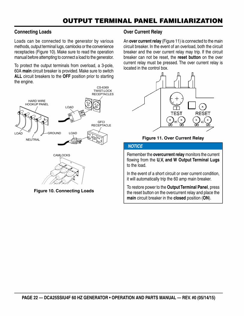
Connecting Loads
Loads can be connected to the generator by various methods, output terminal lugs, camlocks or the convenience receptacles (Figure 10). Make sure to read the operation manual before attempting to connect a load to the generator.
To protect the output terminals from overload, a 3-pole, 60A main circuit breaker is provided. Make sure to switch ALL circuit breakers to the OFF position prior to starting the engine.
Figure 10. Connecting Loads
U
V
W
LOAD
O
NEUTRAL
GROUND
HARD WIREHOOKUP PANEL
LOAD
GFCIRECEPTACLE
LOAD
CS-6369TWIST-LOCK
RECEPTACLES
CAMLOCKS
Over Current Relay
An over current relay (Figure 11) is connected to the main circuit breaker. In the event of an overload, both the circuit breaker and the over current relay may trip. If the circuit breaker can not be reset, the reset button on the over current relay must be pressed. The over current relay is located in the control box.
Figure 11. Over Current Relay
NOTICE
Remember the overcurrent relay monitors the current flowing from the U,V, and W Output Terminal Lugs to the load.
In the event of a short circuit or over current condition, it will automatically trip the 60 amp main breaker.
To restore power to the Output Terminal Panel, press the reset button on the overcurrent relay and place the main circuit breaker in the closed position (ON).
DCA25SSIU4F 60 HZ GENERATOR• OPERATION MANUAL — REV. #0 (05/14/15) — PAGE 23
LOAD APPLICATION
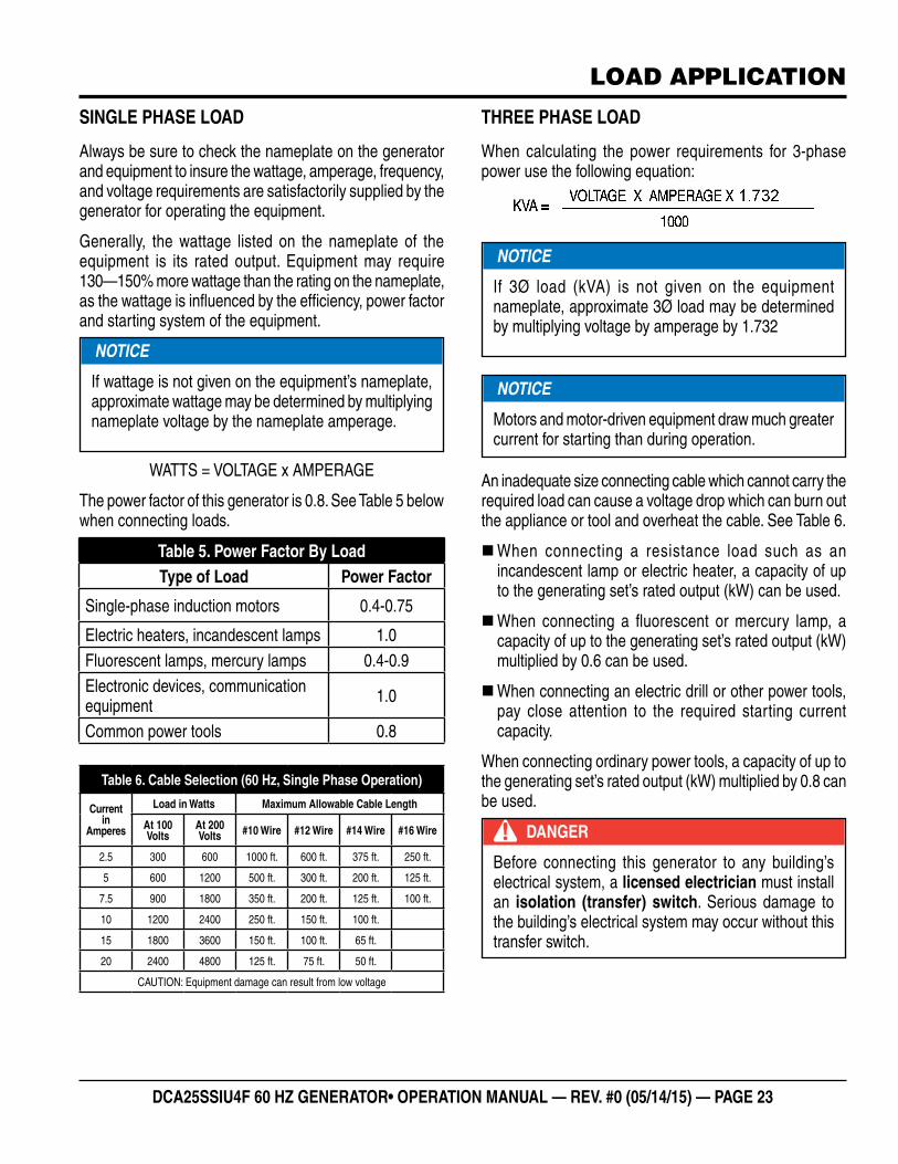
SINGLE PHASE LOAD
Always be sure to check the nameplate on the generator and equipment to insure the wattage, amperage, frequency, and voltage requirements are satisfactorily supplied by the generator for operating the equipment.
Generally, the wattage listed on the nameplate of the equipment is its rated output. Equipment may require 130—150% more wattage than the rating on the nameplate, as the wattage is influenced by the efficiency, power factor and starting system of the equipment.
WATTS = VOLTAGE x AMPERAGE
The power factor of this generator is 0.8. See Table 5 below when connecting loads.
Table 6. Cable Selection (60 Hz, Single Phase Operation)
Current in
Amperes
Load in Watts Maximum Allowable Cable Length
At 100 Volts
At 200 Volts #10 Wire #12 Wire #14 Wire #16 Wire
2.5 300 600 1000 ft. 600 ft. 375 ft. 250 ft.
5 600 1200 500 ft. 300 ft. 200 ft. 125 ft.
7.5 900 1800 350 ft. 200 ft. 125 ft. 100 ft.
10 1200 2400 250 ft. 150 ft. 100 ft.
15 1800 3600 150 ft. 100 ft. 65 ft.
20 2400 4800 125 ft. 75 ft. 50 ft.
CAUTION: Equipment damage can result from low voltage
NOTICE
If wattage is not given on the equipment’s nameplate, approximate wattage may be determined by multiplying nameplate voltage by the nameplate amperage.
Table 5. Power Factor By LoadType of Load Power Factor
Single-phase induction motors 0.4-0.75
Electric heaters, incandescent lamps 1.0Fluorescent lamps, mercury lamps 0.4-0.9Electronic devices, communication equipment 1.0
Common power tools 0.8
THREE PHASE LOAD
When calculating the power requirements for 3-phase power use the following equation:
An inadequate size connecting cable which cannot carry the required load can cause a voltage drop which can burn out the appliance or tool and overheat the cable. See Table 6.
�When connecting a resistance load such as an incandescent lamp or electric heater, a capacity of up to the generating set’s rated output (kW) can be used.
�When connecting a fluorescent or mercury lamp, a capacity of up to the generating set’s rated output (kW) multiplied by 0.6 can be used.
�When connecting an electric drill or other power tools, pay close attention to the required starting current capacity.
When connecting ordinary power tools, a capacity of up to the generating set’s rated output (kW) multiplied by 0.8 can be used.
NOTICE
If 3Ø load (kVA) is not given on the equipment nameplate, approximate 3Ø load may be determined by multiplying voltage by amperage by 1.732
NOTICE
Motors and motor-driven equipment draw much greater current for starting than during operation.
DANGER
Before connecting this generator to any building’s electrical system, a licensed electrician must install an isolation (transfer) switch. Serious damage to the building’s electrical system may occur without this transfer switch.
PAGE 24 — DCA25SSIU4F 60 HZ GENERATOR • OPERATION AND PARTS MANUAL — REV. #0 (05/14/15)
GENERATOR OUTPUTS
GENERATOR OUTPUT VOLTAGES
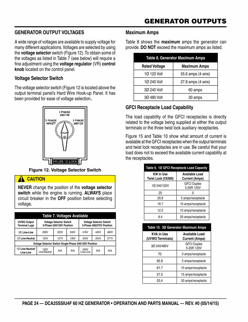
A wide range of voltages are available to supply voltage for many different applications. Voltages are selected by using the voltage selector switch (Figure 12). To obtain some of the voltages as listed in Table 7 (see below) will require a fine adjustment using the voltage regulator (VR) control knob located on the control panel.
Voltage Selector Switch
The voltage selector switch (Figure 12 is located above the output terminal panel’s Hard Wire Hook-up Panel. It has been provided for ease of voltage selection..
Figure 12. Voltage Selector Switch
CAUTION
NEVER change the position of the voltage selector switch while the engine is running. ALWAYS place circuit breaker in the OFF position before selecting voltage.
Table 7. Voltages AvailableUVWO Output Terminal Lugs
Voltage Selector Switch3-Phase 240/139V Position
Voltage Selector Switch3-Phase 480/270V Position
3Ø Line-Line 208V 220V 240V 416V 440V 480V
1Ø Line-Neutral 120V 127V 139V 240V 254V 277V
Voltage Selector Switch Single-Phase 240/120V Position
1Ø Line-Neutral/Line-Line
120V Line-Neutral N/A N/A 240V
Line-Line N/A N/A
Maximum Amps
Table 8 shows the maximum amps the generator can provide. DO NOT exceed the maximum amps as listed.
GFCI Receptacle Load Capability
The load capability of the GFCI receptacles is directly related to the voltage being supplied at either the output terminals or the three twist lock auxiliary receptacles.
Figure 15 and Table 10 show what amount of current is available at the GFCI receptacles when the output terminals and twist lock receptacles are in use. Be careful that your load does not to exceed the available current capability at the receptacles.
Table 8. Generator Maximum Amps
Rated Voltage Maximum Amps
1Ø 120 Volt 55.6 amps (4 wire)
1Ø 240 Volt 27.8 amps (4 wire)
3Ø 240 Volt 60 amps
3Ø 480 Volt 30 amps
Table 9. 1Ø GFCI Receptacle Load Capacity
KW in Use Twist Lock (C6369)
Available Load Current (Amps)
1Ø 240/120V GFCI Duplex 5-20R 120V
25 020.8 5 amps/receptacle
16.7 10 amps/receptacle
12.5 15 amps/receptacle
8.4 20 amps/receptacle
Table 10. 3Ø Generator Maximum Amps
KVA in Use (UVWO Terminals)
Available Load Current (Amps)
3Ø 240/480V GFCI Duplex 5-20R 120V
70 0 amps/receptacle
65.8 5 amps/receptacle
61.7 10 amps/receptacle
57.5 15 amps/receptacle
53.4 20 amps/receptacle
DCA25SSIU4F 60 HZ GENERATOR• OPERATION MANUAL — REV. #0 (05/14/15) — PAGE 25
GENERATOR OUTPUTS/GAUGE READING
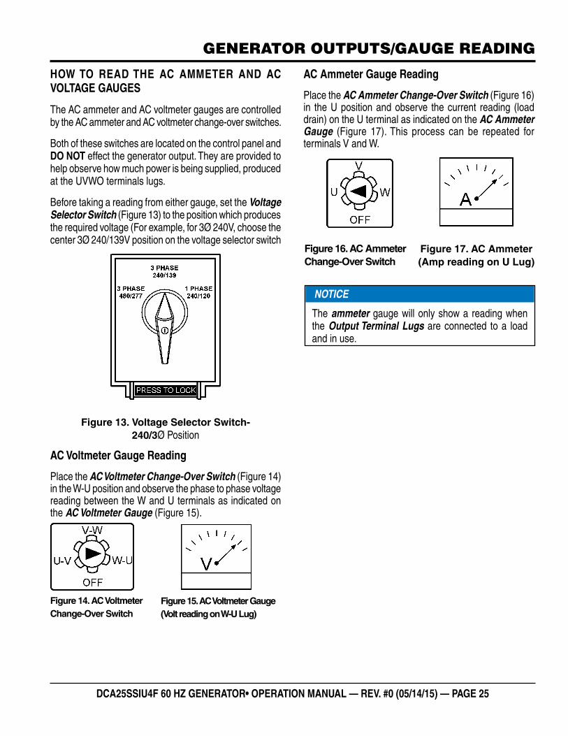
HOW TO READ THE AC AMMETER AND AC VOLTAGE GAUGES
The AC ammeter and AC voltmeter gauges are controlled by the AC ammeter and AC voltmeter change-over switches.
Both of these switches are located on the control panel and DO NOT effect the generator output. They are provided to help observe how much power is being supplied, produced at the UVWO terminals lugs.
Before taking a reading from either gauge, set the Voltage Selector Switch (Figure 13) to the position which produces the required voltage (For example, for 3Ø 240V, choose the center 3Ø 240/139V position on the voltage selector switch
Figure 13. Voltage Selector Switch- 240/3Ø Position
AC Voltmeter Gauge Reading
Place the AC Voltmeter Change-Over Switch (Figure 14) in the W-U position and observe the phase to phase voltage reading between the W and U terminals as indicated on the AC Voltmeter Gauge (Figure 15).
Figure 14. AC Voltmeter Change-Over Switch
Figure 15. AC Voltmeter Gauge (Volt reading on W-U Lug)
AC Ammeter Gauge Reading
Place the AC Ammeter Change-Over Switch (Figure 16) in the U position and observe the current reading (load drain) on the U terminal as indicated on the AC Ammeter Gauge (Figure 17). This process can be repeated for terminals V and W.
Figure 16. AC Ammeter Change-Over Switch
Figure 17. AC Ammeter (Amp reading on U Lug)
NOTICE
The ammeter gauge will only show a reading when the Output Terminal Lugs are connected to a load and in use.
PAGE 26 — DCA25SSIU4F 60 HZ GENERATOR • OPERATION AND PARTS MANUAL — REV. #0 (05/14/15)
OUTPUT TERMINAL PANEL CONNECTIONS
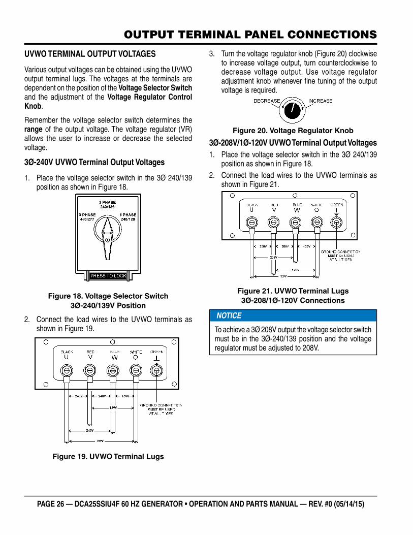
UVWO TERMINAL OUTPUT VOLTAGES
Various output voltages can be obtained using the UVWO output terminal lugs. The voltages at the terminals are dependent on the position of the Voltage Selector Switch and the adjustment of the Voltage Regulator Control Knob.
Remember the voltage selector switch determines the range of the output voltage. The voltage regulator (VR) allows the user to increase or decrease the selected voltage.
3Ø-240V UVWO Terminal Output Voltages
1. Place the voltage selector switch in the 3Ø 240/139 position as shown in Figure 18.
Figure 18. Voltage Selector Switch 3Ø-240/139V Position
2. Connect the load wires to the UVWO terminals as shown in Figure 19.
Figure 19. UVWO Terminal Lugs
3. Turn the voltage regulator knob (Figure 20) clockwise to increase voltage output, turn counterclockwise to decrease voltage output. Use voltage regulator adjustment knob whenever fine tuning of the output voltage is required.
Figure 20. Voltage Regulator Knob
3Ø-208V/1Ø-120V UVWO Terminal Output Voltages1. Place the voltage selector switch in the 3Ø 240/139
position as shown in Figure 18.2. Connect the load wires to the UVWO terminals as
shown in Figure 21.
Figure 21. UVWO Terminal Lugs 3Ø-208/1Ø-120V Connections
NOTICE
To achieve a 3Ø 208V output the voltage selector switch must be in the 3Ø-240/139 position and the voltage regulator must be adjusted to 208V.
DCA25SSIU4F 60 HZ GENERATOR• OPERATION MANUAL — REV. #0 (05/14/15) — PAGE 27
OUTPUT TERMINAL PANEL CONNECTIONS
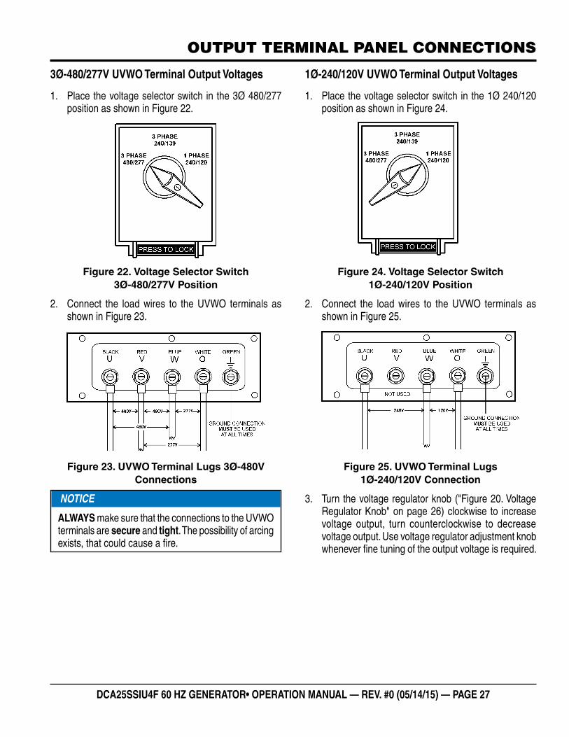
3Ø-480/277V UVWO Terminal Output Voltages
1. Place the voltage selector switch in the 3Ø 480/277 position as shown in Figure 22.
Figure 22. Voltage Selector Switch 3Ø-480/277V Position
2. Connect the load wires to the UVWO terminals as shown in Figure 23.
Figure 23. UVWO Terminal Lugs 3Ø-480V Connections
NOTICE
ALWAYS make sure that the connections to the UVWO terminals are secure and tight. The possibility of arcing exists, that could cause a fire.
1Ø-240/120V UVWO Terminal Output Voltages
1. Place the voltage selector switch in the 1Ø 240/120 position as shown in Figure 24.
Figure 24. Voltage Selector Switch 1Ø-240/120V Position
2. Connect the load wires to the UVWO terminals as shown in Figure 25.
Figure 25. UVWO Terminal Lugs 1Ø-240/120V Connection
3. Turn the voltage regulator knob ("Figure 20. Voltage Regulator Knob" on page 26) clockwise to increase voltage output, turn counterclockwise to decrease voltage output. Use voltage regulator adjustment knob whenever fine tuning of the output voltage is required.
PAGE 28 — DCA25SSIU4F 60 HZ GENERATOR • OPERATION AND PARTS MANUAL — REV. #0 (05/14/15)
INSPECTION/SETUP
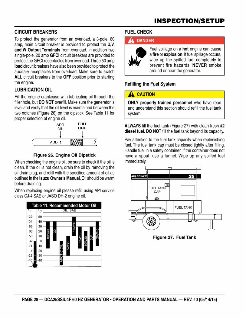
CIRCUIT BREAKERSTo protect the generator from an overload, a 3-pole, 60 amp, main circuit breaker is provided to protect the U,V, and W Output Terminals from overload. In addition two single-pole, 20 amp GFCI circuit breakers are provided to protect the GFCI receptacles from overload. Three 50 amp load circuit breakers have also been provided to protect the auxiliary receptacles from overload. Make sure to switch ALL circuit breakers to the OFF position prior to starting the engine.
LUBRICATION OILFill the engine crankcase with lubricating oil through the filler hole, but DO NOT overfill. Make sure the generator is level and verify that the oil level is maintained between the two notches (Figure 26) on the dipstick. See Table 11 for proper selection of engine oil.
Figure 26. Engine Oil Dipstick
When checking the engine oil, be sure to check if the oil is clean. If the oil is not clean, drain the oil by removing the oil drain plug, and refill with the specified amount of oil as outlined in the Isuzu Owner’s Manual. Oil should be warm before draining.When replacing engine oil please refill using API service class CJ-4 SAE or JASO DH-2 engine oil.
Table 11. Recommended Motor Oil
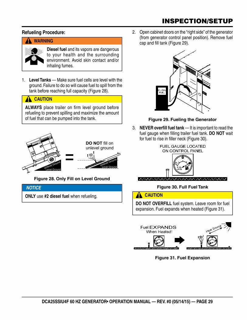
FUEL CHECK
Refilling the Fuel System
ALWAYS fill the fuel tank (Figure 27) with clean fresh #2 diesel fuel. DO NOT fill the fuel tank beyond its capacity.
Pay attention to the fuel tank capacity when replenishing fuel. The fuel tank cap must be closed tightly after filling. Handle fuel in a safety container. If the container does not have a spout, use a funnel. Wipe up any spilled fuel immediately.
Figure 27. Fuel Tank
DANGER
Fuel spillage on a hot engine can cause a fire or explosion. If fuel spillage occurs, wipe up the spilled fuel completely to prevent fire hazards. NEVER smoke around or near the generator.
CAUTION
ONLY properly trained personnel who have read and understand this section should refill the fuel tank system.
FUEL TANK
25
FUEL TANKCAP
DCA25SSIU4F 60 HZ GENERATOR• OPERATION MANUAL — REV. #0 (05/14/15) — PAGE 29
INSPECTION/SETUP
Refueling Procedure:
1. Level Tanks — Make sure fuel cells are level with the ground. Failure to do so will cause fuel to spill from the tank before reaching full capacity (Figure 28).
Figure 28. Only Fill on Level Ground
WARNING
Diesel fuel and its vapors are dangerous to your health and the surrounding environment. Avoid skin contact and/or inhaling fumes.
CAUTION
ALWAYS place trailer on firm level ground before refueling to prevent spilling and maximize the amount of fuel that can be pumped into the tank.
Level GroundUnlevel Ground =
Level GroundUnlevel Ground
DO NOT fill onunlevel ground
!!
70
25
NOTICE
ONLY use #2 diesel fuel when refueling.
2. Open cabinet doors on the “right side” of the generator (from generator control panel position). Remove fuel cap and fill tank (Figure 29).
Figure 29. Fueling the Generator
3. NEVER overfill fuel tank — It is important to read the fuel gauge when filling trailer fuel tank. DO NOT wait for fuel to rise in filler neck (Figure 30).
Figure 30. Full Fuel Tank
Figure 31. Fuel Expansion
CAUTION
DO NOT OVERFILL fuel system. Leave room for fuel expansion. Fuel expands when heated (Figure 31).
PAGE 30 — DCA25SSIU4F 60 HZ GENERATOR • OPERATION AND PARTS MANUAL — REV. #0 (05/14/15)
COOLANT (ANTIFREEZE/SUMMER COOLANT/WATER)
Isuzu recommends antifreeze/summer coolant for use in their engines, which can be purchased in concentrate (and mixed with 50% demineralized water) or pre-diluted. See the Isuzu Engine Owner’s Manual for further details.
Day-to-day addition of coolant is done from the recovery tank. When adding coolant to the radiator, DO NOT remove the radiator cap until the unit has completely cooled. See Table 12 for engine, radiator, and recovery tank coolant capacities. Make sure the coolant level in the recovery tank is always between the “H” and the “L” markings.
Operation in Freezing Weather
When operating in freezing weather, be certain the proper amount of antifreeze (Table 13) has been added.
WARNING
If adding coolant/antifreeze mix to the radiator, DO NOT remove the radiator cap until the unit has completely cooled. The possibility of hot! coolant exists which can cause severe burns.
Table 12. Coolant CapacityEngine and Radiator 2.3 gal (8.8 liters)
Reserve Tank N/A
Table 13. Anti-Freeze Operating Temperatures
Vol % Anti-Freeze
Freezing Point
°C °F
50 -37 -34
NOTICE
When the antifreeze is mixed with water, the antifreeze mixing ratio must be less than 50%.
Cleaning the Radiator
The engine may overheat if the radiator fins become overloaded with dust or debris. Periodically clean the radiator fins with compressed air. Cleaning inside the machine is dangerous, so clean only with the engine turned off and the negative battery terminal disconnected.
AIR CLEANER
Periodic cleaning/replacement is necessary. Inspect air cleaner in accordance with the Isuzu Engine Owner’s Manual.
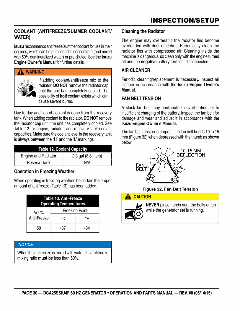
FAN BELT TENSION
A slack fan belt may contribute to overheating, or to insufficient charging of the battery. Inspect the fan belt for damage and wear and adjust it in accordance with the Isuzu Engine Owner’s Manual.
The fan belt tension is proper if the fan belt bends 10 to 15 mm (Figure 32) when depressed with the thumb as shown below.
Figure 32. Fan Belt Tension
CAUTION
NEVER place hands near the belts or fan while the generator set is running.
INSPECTION/SETUP
DCA25SSIU4F 60 HZ GENERATOR• OPERATION MANUAL — REV. #0 (05/14/15) — PAGE 31
BATTERY
This unit is of negative ground DO NOT connect in reverse. Always maintain battery fluid level between the specified marks. Battery life will be shortened, if the fluid level are not properly maintained. Add only distilled water when replenishment is necessary.
DO NOT over fill. Check to see whether the battery cables are loose. Poor contact may result in poor starting or malfunctions. Always keep the terminals firmly tightened. Coating the terminals with an approved battery terminal treatment compound. Replace battery with only recommended type battery. The battery type used in this generator is BCI Group 27.
The battery is sufficiently charged if the specific gravity of the battery fluid is 1.28 (at 68° F). If the specific gravity should fall to 1.245 or lower, it indicates that the battery is dead and needs to be recharged or replaced.
Before charging the battery with an external electric source, be sure to disconnect the battery cables.
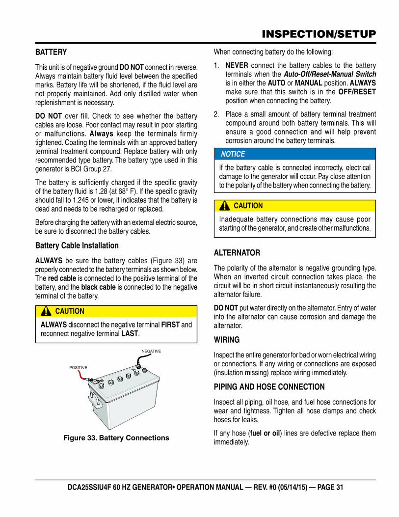
Battery Cable Installation
ALWAYS be sure the battery cables (Figure 33) are properly connected to the battery terminals as shown below. The red cable is connected to the positive terminal of the battery, and the black cable is connected to the negative terminal of the battery.
Figure 33. Battery Connections
CAUTION
ALWAYS disconnect the negative terminal FIRST and reconnect negative terminal LAST.
POSITIVE
NEGATIVE
When connecting battery do the following:
1. NEVER connect the battery cables to the battery terminals when the Auto-Off/Reset-Manual Switch is in either the AUTO or MANUAL position. ALWAYS make sure that this switch is in the OFF/RESET position when connecting the battery.
2. Place a small amount of battery terminal treatment compound around both battery terminals. This will ensure a good connection and will help prevent corrosion around the battery terminals.
ALTERNATOR
The polarity of the alternator is negative grounding type. When an inverted circuit connection takes place, the circuit will be in short circuit instantaneously resulting the alternator failure.
DO NOT put water directly on the alternator. Entry of water into the alternator can cause corrosion and damage the alternator.
WIRING
Inspect the entire generator for bad or worn electrical wiring or connections. If any wiring or connections are exposed (insulation missing) replace wiring immediately.
PIPING AND HOSE CONNECTION
Inspect all piping, oil hose, and fuel hose connections for wear and tightness. Tighten all hose clamps and check hoses for leaks.
If any hose (fuel or oil) lines are defective replace them immediately.
CAUTION
Inadequate battery connections may cause poor starting of the generator, and create other malfunctions.
NOTICE
If the battery cable is connected incorrectly, electrical damage to the generator will occur. Pay close attention to the polarity of the battery when connecting the battery.
INSPECTION/SETUP
PAGE 32 — DCA25SSIU4F 60 HZ GENERATOR • OPERATION AND PARTS MANUAL — REV. #0 (05/14/15)
GENERATOR START-UP PROCEDURE (MANUAL)
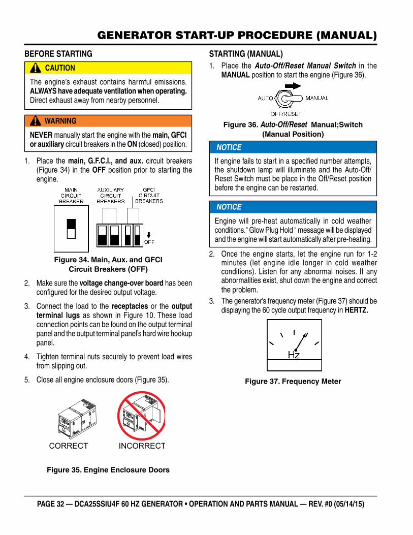
BEFORE STARTING
1. Place the main, G.F.C.I., and aux. circuit breakers (Figure 34) in the OFF position prior to starting the engine.
Figure 34. Main, Aux. and GFCI Circuit Breakers (OFF)
2. Make sure the voltage change-over board has been configured for the desired output voltage.
3. Connect the load to the receptacles or the output terminal lugs as shown in Figure 10. These load connection points can be found on the output terminal panel and the output terminal panel’s hard wire hookup panel.
4. Tighten terminal nuts securely to prevent load wires from slipping out.
5. Close all engine enclosure doors (Figure 35).
Figure 35. Engine Enclosure Doors
CAUTION
The engine’s exhaust contains harmful emissions. ALWAYS have adequate ventilation when operating. Direct exhaust away from nearby personnel.
WARNING
NEVER manually start the engine with the main, GFCI or auxiliary circuit breakers in the ON (closed) position.
INCORRECTCORRECT
STARTING (MANUAL)1. Place the Auto-Off/Reset Manual Switch in the
MANUAL position to start the engine (Figure 36).
Figure 36. Auto-Off/Reset Manual;Switch (Manual Position)
2. Once the engine starts, let the engine run for 1-2 minutes (let engine idle longer in cold weather conditions). Listen for any abnormal noises. If any abnormalities exist, shut down the engine and correct the problem.
3. The generator’s frequency meter (Figure 37) should be displaying the 60 cycle output frequency in HERTZ.
Figure 37. Frequency Meter
NOTICE
If engine fails to start in a specified number attempts, the shutdown lamp will illuminate and the Auto-Off/Reset Switch must be place in the Off/Reset position before the engine can be restarted.
NOTICE
Engine will pre-heat automatically in cold weather conditions." Glow Plug Hold " message will be displayed and the engine will start automatically after pre-heating.
DCA25SSIU4F 60 HZ GENERATOR• OPERATION MANUAL — REV. #0 (05/14/15) — PAGE 33
GENERATOR START-UP PROCEDURE (MANUAL)
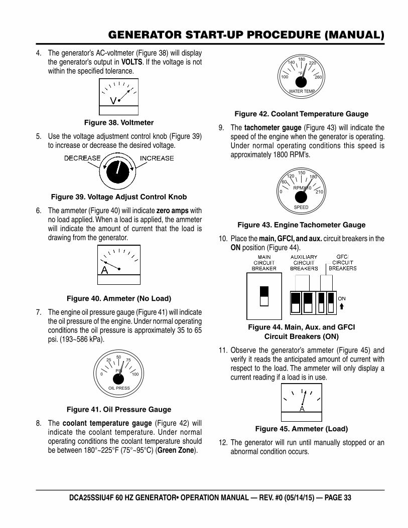
4. The generator’s AC-voltmeter (Figure 38) will display the generator’s output in VOLTS. If the voltage is not within the specified tolerance.
Figure 38. Voltmeter
5. Use the voltage adjustment control knob (Figure 39) to increase or decrease the desired voltage.
Figure 39. Voltage Adjust Control Knob
6. The ammeter (Figure 40) will indicate zero amps with no load applied. When a load is applied, the ammeter will indicate the amount of current that the load is drawing from the generator.
Figure 40. Ammeter (No Load)
7. The engine oil pressure gauge (Figure 41) will indicate the oil pressure of the engine. Under normal operating conditions the oil pressure is approximately 35 to 65 psi. (193~586 kPa).
Figure 41. Oil Pressure Gauge
8. The coolant temperature gauge (Figure 42) will indicate the coolant temperature. Under normal operating conditions the coolant temperature should be between 180°~225°F (75°~95°C) (Green Zone).
PSI
OIL PRESS
0
2550
75
100
Figure 42. Coolant Temperature Gauge
9. The tachometer gauge (Figure 43) will indicate the speed of the engine when the generator is operating. Under normal operating conditions this speed is approximately 1800 RPM’s.
Figure 43. Engine Tachometer Gauge
10. Place the main, GFCI, and aux. circuit breakers in the ON position (Figure 44).
Figure 44. Main, Aux. and GFCI Circuit Breakers (ON)
11. Observe the generator’s ammeter (Figure 45) and verify it reads the anticipated amount of current with respect to the load. The ammeter will only display a current reading if a load is in use.
Figure 45. Ammeter (Load)
12. The generator will run until manually stopped or an abnormal condition occurs.
°F
WATER TEMP
100
140180
220
260
RPMX10
SPEED
0
120150
180
210
60
PAGE 34 — DCA25SSIU4F 60 HZ GENERATOR • OPERATION AND PARTS MANUAL — REV. #0 (05/14/15)
GENERATOR START-UP PROCEDURE (AUTO MODE)
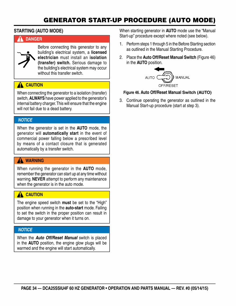
STARTING (AUTO MODE)
DANGER
Before connecting this generator to any building’s electrical system, a licensed electrician must install an isolation (transfer) switch. Serious damage to the building’s electrical system may occur without this transfer switch.
CAUTION
When connecting the generator to a isolation (transfer) switch, ALWAYS have power applied to the generator’s internal battery charger. This will ensure that the engine will not fail due to a dead battery.
WARNING
When running the generator in the AUTO mode, remember the generator can start up at any time without warning. NEVER attempt to perform any maintenance when the generator is in the auto mode.
CAUTION
The engine speed switch must be set to the “High” position when running in the auto-start mode. Failing to set the switch in the proper position can result in damage to your generator when it turns on.
NOTICE
When the generator is set in the AUTO mode, the generator will automatically start in the event of commercial power falling below a prescribed level by means of a contact closure that is generated automatically by a transfer switch.
NOTICE
When the Auto Off/Reset Manual switch is placed in the AUTO position, the engine glow plugs will be warmed and the engine will start automatically.
When starting generator in AUTO mode use the “Manual Start-up” procedure except where noted (see below).
1. Perform steps 1 through 5 in the Before Starting section as outlined in the Manual Starting Procedure.
2. Place the Auto Off/Reset Manual Switch (Figure 46) in the AUTO position.
Figure 46. Auto Off/Reset Manual Switch (AUTO)
3. Continue operating the generator as outlined in the Manual Start-up procedure (start at step 3).
DCA25SSIU4F 60 HZ GENERATOR• OPERATION MANUAL — REV. #0 (05/14/15) — PAGE 35
GENERATOR SHUT-DOWN PROCEDURES
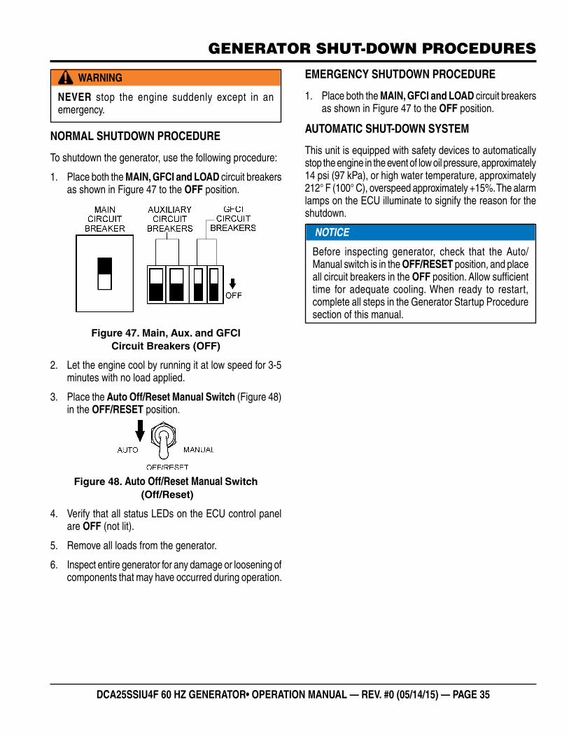
NORMAL SHUTDOWN PROCEDURE
To shutdown the generator, use the following procedure:
1. Place both the MAIN, GFCI and LOAD circuit breakers as shown in Figure 47 to the OFF position.
Figure 47. Main, Aux. and GFCI Circuit Breakers (OFF)
2. Let the engine cool by running it at low speed for 3-5 minutes with no load applied.
3. Place the Auto Off/Reset Manual Switch (Figure 48) in the OFF/RESET position.
Figure 48. Auto Off/Reset Manual Switch (Off/Reset)
4. Verify that all status LEDs on the ECU control panel are OFF (not lit).
5. Remove all loads from the generator.
6. Inspect entire generator for any damage or loosening of components that may have occurred during operation.
WARNING
NEVER stop the engine suddenly except in an emergency.
EMERGENCY SHUTDOWN PROCEDURE
1. Place both the MAIN, GFCI and LOAD circuit breakers as shown in Figure 47 to the OFF position.
AUTOMATIC SHUT-DOWN SYSTEM
This unit is equipped with safety devices to automatically stop the engine in the event of low oil pressure, approximately 14 psi (97 kPa), or high water temperature, approximately 212° F (100° C), overspeed approximately +15%. The alarm lamps on the ECU illuminate to signify the reason for the shutdown.
NOTICE
Before inspecting generator, check that the Auto/Manual switch is in the OFF/RESET position, and place all circuit breakers in the OFF position. Allow sufficient time for adequate cooling. When ready to restart, complete all steps in the Generator Startup Procedure section of this manual.
PAGE 36 — DCA25SSIU4F 60 HZ GENERATOR • OPERATION AND PARTS MANUAL — REV. #0 (05/14/15)
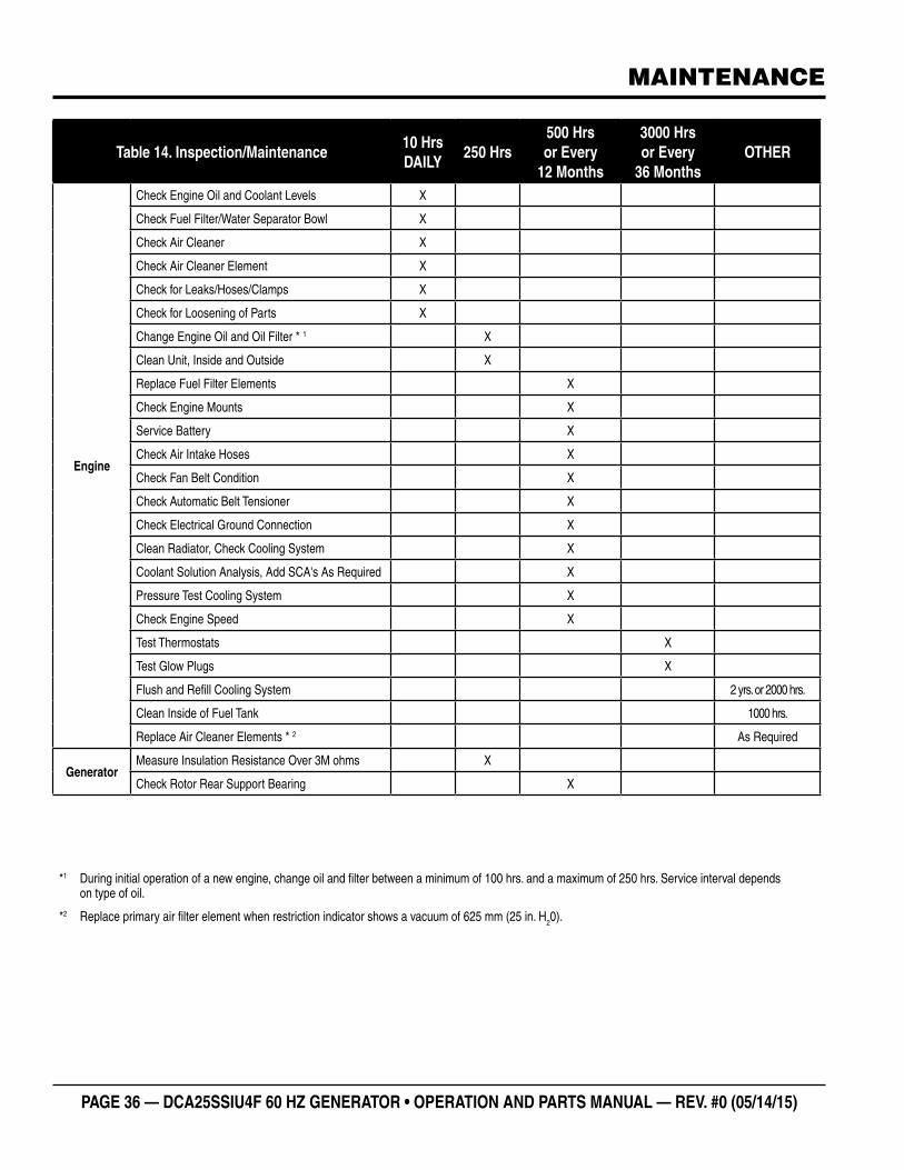
Table 14. Inspection/Maintenance10 Hrs DAILY
250 Hrs500 Hrs or Every
12 Months
3000 Hrs or Every
36 MonthsOTHER
Engine
Check Engine Oil and Coolant Levels X
Check Fuel Filter/Water Separator Bowl X
Check Air Cleaner X
Check Air Cleaner Element X
Check for Leaks/Hoses/Clamps X
Check for Loosening of Parts X
Change Engine Oil and Oil Filter * 1 X
Clean Unit, Inside and Outside X
Replace Fuel Filter Elements X
Check Engine Mounts X
Service Battery X
Check Air Intake Hoses X
Check Fan Belt Condition X
Check Automatic Belt Tensioner X
Check Electrical Ground Connection X
Clean Radiator, Check Cooling System X
Coolant Solution Analysis, Add SCA's As Required X
Pressure Test Cooling System X
Check Engine Speed X
Test Thermostats X
Test Glow Plugs X
Flush and Refill Cooling System 2 yrs. or 2000 hrs.
Clean Inside of Fuel Tank 1000 hrs.
Replace Air Cleaner Elements * 2 As Required
GeneratorMeasure Insulation Resistance Over 3M ohms X
Check Rotor Rear Support Bearing X
*1 During initial operation of a new engine, change oil and filter between a minimum of 100 hrs. and a maximum of 250 hrs. Service interval depends on type of oil.
*2 Replace primary air filter element when restriction indicator shows a vacuum of 625 mm (25 in. H20).
MAINTENANCE
DCA25SSIU4F 60 HZ GENERATOR• OPERATION MANUAL — REV. #0 (05/14/15) — PAGE 37
MAINTENANCE
GENERAL INSPECTIONPrior to each use, the generator should be cleaned and inspected for deficiencies. Check for loose, missing or damaged nuts, bolts or other fasteners. Also check for fuel, oil, and coolant leaks. Use Table 14 as a general maintenance guideline Engine Side (Refer to the Engine Instruction Manual).
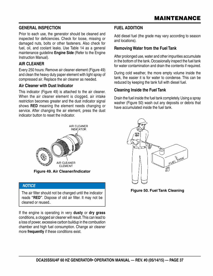
AIR CLEANEREvery 250 hours: Remove air cleaner element (Figure 49) and clean the heavy duty paper element with light spray of compressed air. Replace the air cleaner as needed.
Air Cleaner with Dust IndicatorThis indicator (Figure 49) is attached to the air cleaner. When the air cleaner element is clogged, air intake restriction becomes greater and the dust indicator signal shows RED meaning the element needs changing or service. After changing the air element, press the dust indicator button to reset the indicator.
Figure 49. Air Cleaner/Indicator
If the engine is operating in very dusty or dry grass conditions, a clogged air cleaner will result. This can lead to a loss of power, excessive carbon buildup in the combustion chamber and high fuel consumption. Change air cleaner more frequently if these conditions exist.
NOTICE
The air filter should not be changed until the indicator reads “RED”. Dispose of old air filter. It may not be cleaned or reused..
FUEL ADDITION
Add diesel fuel (the grade may vary according to season and locations).
Removing Water from the Fuel Tank
After prolonged use, water and other impurities accumulate in the bottom of the tank. Occasionally inspect the fuel tank for water contamination and drain the contents if required.
During cold weather, the more empty volume inside the tank, the easier it is for water to condense. This can be reduced by keeping the tank full with diesel fuel.
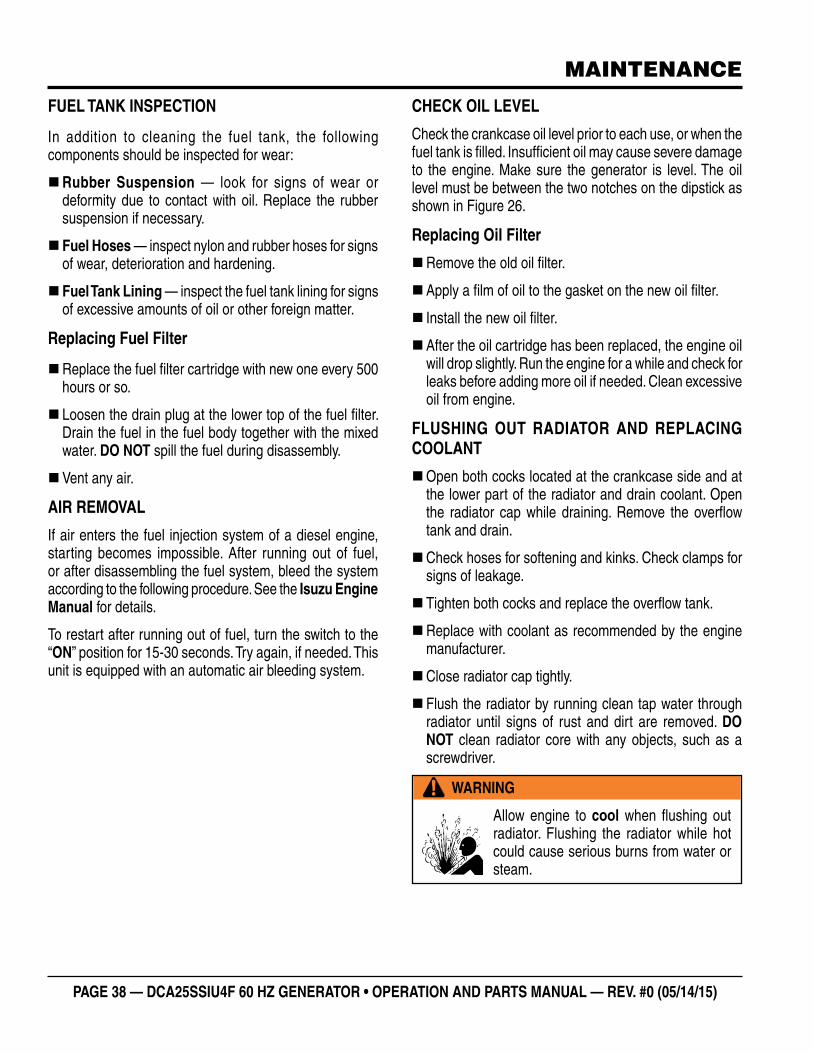
Cleaning Inside the Fuel Tank
Drain the fuel inside the fuel tank completely. Using a spray washer (Figure 50) wash out any deposits or debris that have accumulated inside the fuel tank.
Figure 50. Fuel Tank Cleaning
PAGE 38 — DCA25SSIU4F 60 HZ GENERATOR • OPERATION AND PARTS MANUAL — REV. #0 (05/14/15)
FUEL TANK INSPECTION
In addition to cleaning the fuel tank, the following components should be inspected for wear:
�Rubber Suspension — look for signs of wear or deformity due to contact with oil. Replace the rubber suspension if necessary.
� Fuel Hoses — inspect nylon and rubber hoses for signs of wear, deterioration and hardening.
� Fuel Tank Lining — inspect the fuel tank lining for signs of excessive amounts of oil or other foreign matter.
Replacing Fuel Filter
�Replace the fuel filter cartridge with new one every 500 hours or so.
� Loosen the drain plug at the lower top of the fuel filter. Drain the fuel in the fuel body together with the mixed water. DO NOT spill the fuel during disassembly.
�Vent any air.
AIR REMOVAL
If air enters the fuel injection system of a diesel engine, starting becomes impossible. After running out of fuel, or after disassembling the fuel system, bleed the system according to the following procedure. See the Isuzu Engine Manual for details.
To restart after running out of fuel, turn the switch to the “ON” position for 15-30 seconds. Try again, if needed. This unit is equipped with an automatic air bleeding system.
CHECK OIL LEVEL
Check the crankcase oil level prior to each use, or when the fuel tank is filled. Insufficient oil may cause severe damage to the engine. Make sure the generator is level. The oil level must be between the two notches on the dipstick as shown in Figure 26.
Replacing Oil Filter
�Remove the old oil filter.
�Apply a film of oil to the gasket on the new oil filter.
� Install the new oil filter.
�After the oil cartridge has been replaced, the engine oil will drop slightly. Run the engine for a while and check for leaks before adding more oil if needed. Clean excessive oil from engine.
FLUSHING OUT RADIATOR AND REPLACING COOLANT
�Open both cocks located at the crankcase side and at the lower part of the radiator and drain coolant. Open the radiator cap while draining. Remove the overflow tank and drain.
�Check hoses for softening and kinks. Check clamps for signs of leakage.
� Tighten both cocks and replace the overflow tank.
�Replace with coolant as recommended by the engine manufacturer.
�Close radiator cap tightly.
� Flush the radiator by running clean tap water through radiator until signs of rust and dirt are removed. DO NOT clean radiator core with any objects, such as a screwdriver.
WARNING
Allow engine to cool when flushing out radiator. Flushing the radiator while hot could cause serious burns from water or steam.
MAINTENANCE
DCA25SSIU4F 60 HZ GENERATOR• OPERATION MANUAL — REV. #0 (05/14/15) — PAGE 39
MAINTENANCE
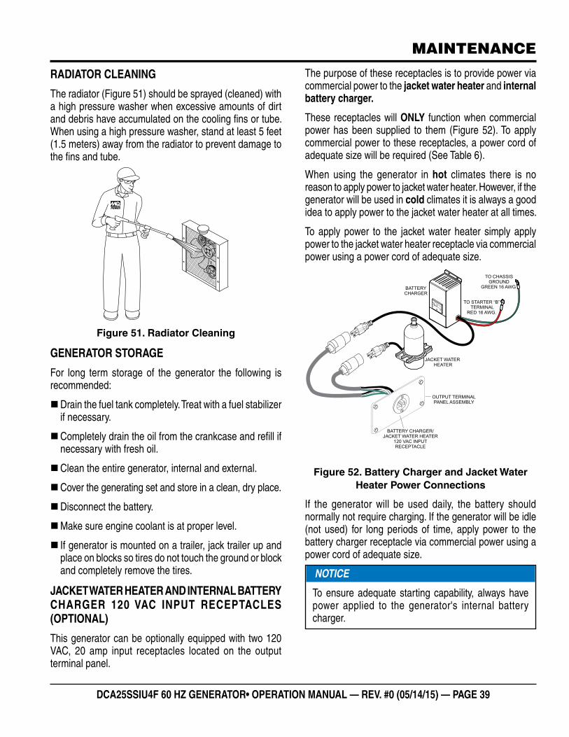
RADIATOR CLEANING
The radiator (Figure 51) should be sprayed (cleaned) with a high pressure washer when excessive amounts of dirt and debris have accumulated on the cooling fins or tube. When using a high pressure washer, stand at least 5 feet (1.5 meters) away from the radiator to prevent damage to the fins and tube.
Figure 51. Radiator Cleaning
GENERATOR STORAGE
For long term storage of the generator the following is recommended:
�Drain the fuel tank completely. Treat with a fuel stabilizer if necessary.
�Completely drain the oil from the crankcase and refill if necessary with fresh oil.
�Clean the entire generator, internal and external.
�Cover the generating set and store in a clean, dry place.
�Disconnect the battery.
�Make sure engine coolant is at proper level.
� If generator is mounted on a trailer, jack trailer up and place on blocks so tires do not touch the ground or block and completely remove the tires.
JACKET WATER HEATER AND INTERNAL BATTERY CHARGER 120 VAC INPUT RECEPTACLES (OPTIONAL)
This generator can be optionally equipped with two 120 VAC, 20 amp input receptacles located on the output terminal panel.
The purpose of these receptacles is to provide power via commercial power to the jacket water heater and internal battery charger.
These receptacles will ONLY function when commercial power has been supplied to them (Figure 52). To apply commercial power to these receptacles, a power cord of adequate size will be required (See Table 6).
When using the generator in hot climates there is no reason to apply power to jacket water heater. However, if the generator will be used in cold climates it is always a good idea to apply power to the jacket water heater at all times.
To apply power to the jacket water heater simply apply power to the jacket water heater receptacle via commercial power using a power cord of adequate size.
Figure 52. Battery Charger and Jacket Water Heater Power Connections
If the generator will be used daily, the battery should normally not require charging. If the generator will be idle (not used) for long periods of time, apply power to the battery charger receptacle via commercial power using a power cord of adequate size.
BATTERYCHARGER
BATTERY CHARGER/JACKET WATER HEATER
120 VAC INPUTRECEPTACLE
OUTPUT TERMINALPANEL ASSEMBLY
JACKET WATERHEATER
TO STARTER “B”TERMINAL
RED 16 AWG.
TO CHASSISGROUND
GREEN 16 AWG.
NOTICE
To ensure adequate starting capability, always have power applied to the generator's internal battery charger.
PAGE 40 — DCA25SSIU4F 60 HZ GENERATOR • OPERATION AND PARTS MANUAL — REV. #0 (05/14/15)
MAINTENANCE
EMISSION CONTROL
The emission control system employed with the Isuzu 4LE2T diesel engine consist of a Diesel Oxidation Catalyst (DOC).
This device oxidizes large amounts of harmful nitrogen oxides (NOx) and particulate matter (PM) which are emitted by diesel engines. These exhaust emissions pose serious environmental and health risks. No maintenance or service is required for the DOC device used on this generator.
Diesel Oxidation Catalyst (DOC)
The DOC does not filter particles it oxidizes them. This catalyst (honeycomb like structure) uses a chemical process to break down pollutants in the exhaust stream into less harmful components. In general this catalyst collects/burns accumulated particulates. The DOC contains palladium and platinum which serve as a catalysts to oxidize hydrocarbons and carbon monoxide.
DCA25SSIU4F 60 HZ GENERATOR• OPERATION MANUAL — REV. #0 (05/14/15) — PAGE 41
TRAILER MAINTENANCE
The following trailer maintenance guidelines are intended to assist the operator in preventive maintenance.
TRAILER BRAKES
Properly functioning brake shoes and drums are essential to ensure safety. The brakes should be inspected the first 200 miles of operation. This will allow the brake shoes and drums to seat properly. After the first 200 mile interval, inspect the brakes every 3,000 miles. If driving over rough terrain, inspect the brakes more frequently.
HYDRAULIC BRAKES
If your trailer has hydraulic brakes, they function the same way the surge brakes do on your tow vehicle. The hydraulic braking system must be inspected at least as often as the brakes on the tow vehicle, but no less than once per year. This inspection includes an assessment of the condition and proper operation of the wheel cylinders, brake shoes, brake drums and hubs.
MANUALLY ADJUSTING THE BRAKES
Most axles are fitted with a brake mechanism that will adjust the brakes during a hard stop. However, some braking systems are not automatically adjusted by hard stopping. These brakes require manual adjustment. The following steps apply to adjust most manually adjustable brakes.
1. Jack up the trailer and secure it on adequate capacity jackstands.
2. Be sure the wheel and brake drum rotate freely.
3. Remove the adjusting-hole cover from the adjusting slot on the bottom of the brake backing plate.
4. With a screwdriver or standard adjusting tool, rotate the starwheel of the adjuster assembly to expand the brake shoes. Adjust the brake shoes out until the pressure of the linings against the drum makes the wheel very difficult to turn. Note: Your trailer maybe equipped with drop spindle axles. See axle manual for your axle type. You will need a modified adjusting tool for adjusting the brakes in these axles. With drop spindle axles, a modified adjusting tool with about an 80 degree angle should be used.
5. Rotate the starwheel in the opposite direction until the wheel turns freely with a slight drag.
6. Replace the adjusting-hole cover.
7. Repeat the above procedure on all brakes.
8. Lower the trailer to the ground.
Check the fluid level in the master cylinder reservoir at least every three months. If you tow your trailer an average of 1,000 miles per month in a hot and dry environment, you must check the brake fluid level once a month. The brake fluid reservoir is located on the tongue of the trailer. Always fill with clean, uncontaminated DOT 4 brake fluid.
Figure 53 below displays the major hydraulic brake components that will require inspection and maintenance. Please inspect these components as required using steps 1 through 6 as referenced in the “Manually Adjusting The Brakes” section on this page. See Table 1 for Hydraulic Brake Troubleshooting.
Figure 53. Hydraulic Brake Components
HYDRAULIC BRAKE ACTUATOR
The hydraulic brake actuator (Figure 54) is the mechanism that activates the trailer’s brake system. This actuator changes fluid power into mechanical power. Therefore, the fluid level must be checked frequently to assure that the brakes function properly.
Figure 54. Hydraulic Brake Actuator
HYDRAULIC
BRAKE FLUID
RESERVOIR
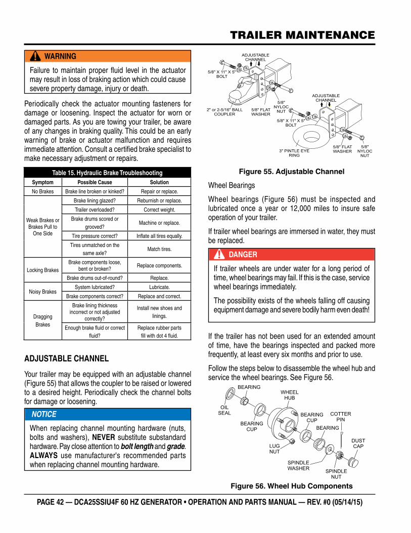
PAGE 42 — DCA25SSIU4F 60 HZ GENERATOR • OPERATION AND PARTS MANUAL — REV. #0 (05/14/15)
TRAILER MAINTENANCE
Periodically check the actuator mounting fasteners for damage or loosening. Inspect the actuator for worn or damaged parts. As you are towing your trailer, be aware of any changes in braking quality. This could be an early warning of brake or actuator malfunction and requires immediate attention. Consult a certified brake specialist to make necessary adjustment or repairs.
ADJUSTABLE CHANNEL
Your trailer may be equipped with an adjustable channel (Figure 55) that allows the coupler to be raised or lowered to a desired height. Periodically check the channel bolts for damage or loosening.
WARNING
Failure to maintain proper fluid level in the actuator may result in loss of braking action which could cause severe property damage, injury or death.
Table 15. Hydraulic Brake TroubleshootingSymptom Possible Cause Solution
No Brakes Brake line broken or kinked? Repair or replace.
Weak Brakes or Brakes Pull to
One Side
Brake lining glazed? Reburnish or replace.
Trailer overloaded? Correct weight.
Brake drums scored or grooved?
Machine or replace.
Tire pressure correct? Inflate all tires equally.
Tires unmatched on the same axle?
Match tires.
Locking BrakesBrake components loose,
bent or broken? Replace components.
Brake drums out-of-round? Replace.
Noisy BrakesSystem lubricated? Lubricate.
Brake components correct? Replace and correct.
Dragging Brakes
Brake lining thickness incorrect or not adjusted
correctly?
Install new shoes and linings.
Enough brake fluid or correct fluid?
Replace rubber parts fill with dot 4 fluid.
NOTICE
When replacing channel mounting hardware (nuts, bolts and washers), NEVER substitute substandard hardware. Pay close attention to bolt length and grade. ALWAYS use manufacturer's recommended parts when replacing channel mounting hardware.
Figure 55. Adjustable Channel
Wheel Bearings
Wheel bearings (Figure 56) must be inspected and lubricated once a year or 12,000 miles to insure safe operation of your trailer.
If trailer wheel bearings are immersed in water, they must be replaced.
If the trailer has not been used for an extended amount of time, have the bearings inspected and packed more frequently, at least every six months and prior to use.
Follow the steps below to disassemble the wheel hub and service the wheel bearings. See Figure 56.
Figure 56. Wheel Hub Components
2" or 2-5/16" BALLCOUPLER
ADJUSTABLECHANNEL
5/8" FLATWASHER
5/8" X 11" X 5"BOLT
5/8"NYLOC
NUT
ADJUSTABLECHANNEL
5/8" FLATWASHER
5/8"NYLOC
NUT
5/8" X 11" X 5"BOLT
3" PINTLE EYERING
DANGER
If trailer wheels are under water for a long period of time, wheel bearings may fail. If this is the case, service wheel bearings immediately.
The possibility exists of the wheels falling off causing equipment damage and severe bodily harm even death!
WHEELHUB
BEARINGCUP
BEARINGCUP
BEARING
BEARING
OILSEAL
SPINDLENUT
SPINDLEWASHER
COTTERPIN
DUSTCAPLUG
NUT
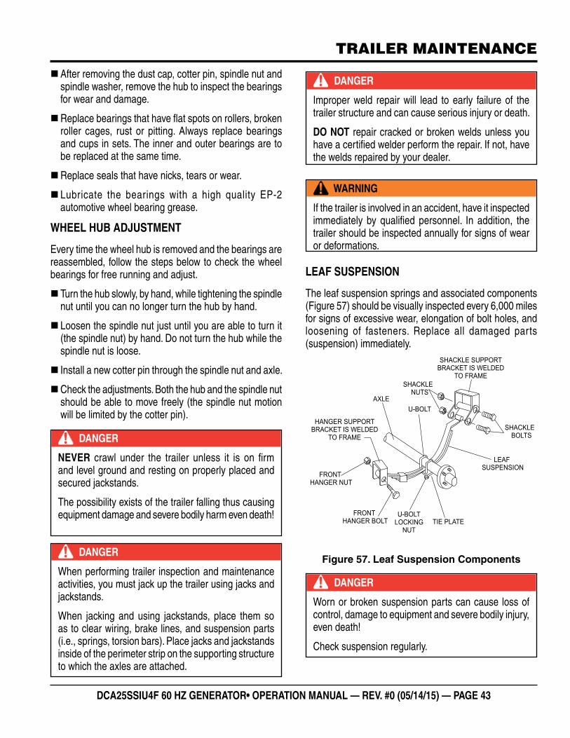
DCA25SSIU4F 60 HZ GENERATOR• OPERATION MANUAL — REV. #0 (05/14/15) — PAGE 43
TRAILER MAINTENANCE
�After removing the dust cap, cotter pin, spindle nut and spindle washer, remove the hub to inspect the bearings for wear and damage.
�Replace bearings that have flat spots on rollers, broken roller cages, rust or pitting. Always replace bearings and cups in sets. The inner and outer bearings are to be replaced at the same time.
�Replace seals that have nicks, tears or wear.
� Lubricate the bearings with a high quality EP-2 automotive wheel bearing grease.
WHEEL HUB ADJUSTMENT
Every time the wheel hub is removed and the bearings are reassembled, follow the steps below to check the wheel bearings for free running and adjust.
� Turn the hub slowly, by hand, while tightening the spindle nut until you can no longer turn the hub by hand.
� Loosen the spindle nut just until you are able to turn it (the spindle nut) by hand. Do not turn the hub while the spindle nut is loose.
� Install a new cotter pin through the spindle nut and axle.
�Check the adjustments. Both the hub and the spindle nut should be able to move freely (the spindle nut motion will be limited by the cotter pin).
DANGER
NEVER crawl under the trailer unless it is on firm and level ground and resting on properly placed and secured jackstands.
The possibility exists of the trailer falling thus causing equipment damage and severe bodily harm even death!
DANGER
When performing trailer inspection and maintenance activities, you must jack up the trailer using jacks and jackstands.
When jacking and using jackstands, place them so as to clear wiring, brake lines, and suspension parts (i.e., springs, torsion bars). Place jacks and jackstands inside of the perimeter strip on the supporting structure to which the axles are attached.
LEAF SUSPENSION
The leaf suspension springs and associated components (Figure 57) should be visually inspected every 6,000 miles for signs of excessive wear, elongation of bolt holes, and loosening of fasteners. Replace all damaged parts (suspension) immediately.
Figure 57. Leaf Suspension Components
DANGER
Improper weld repair will lead to early failure of the trailer structure and can cause serious injury or death.
DO NOT repair cracked or broken welds unless you have a certified welder perform the repair. If not, have the welds repaired by your dealer.
WARNING
If the trailer is involved in an accident, have it inspected immediately by qualified personnel. In addition, the trailer should be inspected annually for signs of wear or deformations.
U-BOLT
LEAFSUSPENSION
TIE PLATE
AXLE
U-BOLTLOCKING
NUT
SHACKLEBOLTS
FRONTHANGER BOLT
FRONTHANGER NUT
SHACKLENUTS
SHACKLE SUPPORTBRACKET IS WELDED
TO FRAME
HANGER SUPPORTBRACKET IS WELDED
TO FRAME
DANGER
Worn or broken suspension parts can cause loss of control, damage to equipment and severe bodily injury, even death!
Check suspension regularly.
PAGE 44 — DCA25SSIU4F 60 HZ GENERATOR • OPERATION AND PARTS MANUAL — REV. #0 (05/14/15)
TRAILER GUIDELINES
The following guidelines are intended to assist the operator in the operation and handling of a trailer.
Safety precautions should be followed at all times when operating a trailer. Failure to read, understand and follow the safety guidelines could result in injury to yourself and others. Loss of control of the trailer or tow vehicle can result in death or serious injury.
COMMON CAUSES FOR LOSS OF TRAILER
�Driving too fast for the conditions (maximum speed when towing a trailer is 55 mph).
�Overloading the trailer or loading the trailer unevenly.
� Trailer improperly coupled to the hitch.
�No braking on trailer.
�Not maintaining proper tire pressure.
�Not keeping lug nuts tight.
�Not properly maintaining the trailer structure.
�Ensure machine is towed level to tow vehicle.
TRAILER TOWING GUIDELINES
�Recheck the load tiedowns to make sure the load will not shift during towing.
�Before towing, check coupling, safety chain, safety brake, tires, wheels and lights.
�Check the lug nuts or bolts for tightness.
�Check coupler tightness after towing 50 miles.
�Use your mirrors to verify that you have room to change lanes or pull into traffi c.
�Use your turn signals well in advance. Allow plenty of stopping space for your trailer and tow vehicle.
�Allow plenty of stopping space for your trailer and tow vehicle.
�DO NOT drive so fast that the trailer begins to sway due to speed.
�Allow plenty of room for passing. A rule of thumb is that the passing distance with a trailer is 4 times the passing distance without the trailer.
�Shift your automatic transmission into a lower gear for city driving.
�ALWAYS use lower gears for climbing and descending grades.
�DO NOT ride the brakes while descending grades, they may get so hot that they stop working. Then you will potentially have a runaway tow vehicle and trailer.
� To conserve fuel, don’t use full throttle to climb a hill. Instead, build speed on the approach.
�Slow down for bumps in the road. Take your foot off the brake when crossing the bump.
�DO NOT brake while in a curve unless absolutely necessary. Instead, slow down before you enter the curve and power through the curve. This way, the towing vehicle remains in charge.
�DO NOT apply the brakes to correct extreme trailer swaying. Continued pulling of the trailer, and even slight acceleration, will provide a stabilizing force.
�Anticipate the trailer “swaying.” Swaying is the trailer reaction to the air pressure wave caused by passing trucks and buses. Continued pulling of the trailer provides a stabilizing force to correct swaying. DO NOT apply the brakes to correct trailer swaying.
�Use lower gear when driving down steep or long grades. Use the engine and transmission as a brake. Do not ride the brakes, as they can overheat and become ineffective.
�Be aware of your trailer height, especially when approaching roofed areas and around trees.
�Make regular stops, about once each hour. Confi rm that:
• Coupler is secure to the hitch and is locked.
• Electrical connectors are secure.
• There is appropriate slack in the safety chains.
• There is appropriate slack in the breakaway switch pullpin cable.
• Tires are not visibly low on pressure.
DCA25SSIU4F 60 HZ GENERATOR• OPERATION MANUAL — REV. #0 (05/14/15) — PAGE 45
TRAILER GUIDELINES
DRIVING CONDITIONS
When towing a trailer, you will have decreased acceleration, increased stopping distance, and increased turning radius (which means you must make wider turns to keep from hitting curbs, vehicles, and anything else that is on the inside corner). In addition, you will need a longer distance to pass, due to slower acceleration and increased length.
�Be alert for slippery conditions. You are more likely to be affected by slippery road surfaces when driving a tow vehicle with a trailer, than driving a tow vehicle without a trailer.
�Check rearview mirrors frequently to observe the trailer and traffi c.
�NEVER drive faster than what is safe.
COUPLING TO THE TOW VEHICLE
Follow all of the safety precautions and instructions in this manual to ensure safety of persons, equipment, and satisfactory life of the trailer. Always use an adequate tow vehicle and hitch. If the vehicle or hitch is not properly selected and matched to the Gross Vehicle Weight Rating (GVWR) of your trailer, you can cause an accident that could lead to death or serious injury.
If you already have a tow vehicle, know your vehicle tow rating and make certain the trailer’s rated capacity is less than or equal to the tow vehicle’s rated towing capacity. If you already have (or plan to buy) a trailer, make certain that the tow rating of the tow vehicle is equal to or greater than that of the trailer.
The trailer VIN tag contains the critical safetyinformation
WARNING
Driving too fast for severe road conditions can result in loss of control and cause death or serious injury.
Decrease your speed as road, weather, and lighting conditions deteriorate.
Always check for local trailer tow speed limits in your area.
WARNING
Do not transport people on the trailer. The transport of people puts their lives at risk and may be illegal.
for the use of your trailer. Again, be sure your hitch and tow vehicle are rated for the Gross Vehicle Weight Rating of your trailer.
WARNING
Proper selection and condition of the coupler and hitch are essential to safely towing your trailer. A loss of coupling may result in death or serious injury.
• Be sure the hitch load rating is equal to or greater than the load rating of the coupler.
• Be sure the hitch size matches the coupler size.• Observe the hitch for wear, corrosion and cracks
before coupling. Replace worn, corroded or cracked hitch components before coupling the trailer to the tow vehicle.
• Be sure the hitch components are tight before coupling the trailer to the tow vehicle.
WARNING
An improperly coupled trailer can result in death or serious injury.
DO NOT move the trailer until:• The coupler is secured and locked to hitch.• The safety chains are secured to the tow vehicle.• The trailer jack(s) are fully retracted.
DO NOT tow the trailer on the road until:• Tires and wheels are checked.• The trailer brakes are checked.• The breakaway switch is connected to the tow
vehicle.• The load is secured to the trailer.• The trailer lights are connected and checked.
WARNING
Use of a hitch with a load rating less than the load rating of the trailer can result in loss of control and may lead to death or serious injury.
Use of a tow vehicle with a towing capacity less than the load rating of the trailer can result in loss of control, and may lead to death or serious injury.
Be sure your hitch and tow vehicle are rated for the Gross Vehicle Weight Rating of your trailer.

PAGE 46 — DCA25SSIU4F 60 HZ GENERATOR • OPERATION AND PARTS MANUAL — REV. #0 (05/14/15)
TRAILER GUIDELINES
INOPERABLE BRAKES, LIGHTS OR MIRRORS
Be sure that the brakes and all of the lights on your trailer are functioning properly before towing your trailer. Check the trailer taillights by turning on your tow vehicle headlights. Check the trailer brake lights by having someone step on the tow vehicle brake pedal while you look at trailer lights. Do the same thing to check the turn signal lights. See Trailer Wiring Diagram section in this manual.
Standard mirrors usually do not provide adequate visibility for viewing traffi c to the sides and rear of a towed trailer. You must provide mirrors that allow you to safely observe approaching traffi c.
TRAILER TOWING TIPS
Driving a vehicle with a trailer in tow is vastly different from driving the same vehicle without a trailer in tow. Acceleration, maneuverability and braking are all diminished with a trailer in tow.
It takes longer to get up to speed, you need more room to turn and pass, and more distance to stop when towing a trailer. You will need to spend time adjusting to the different feel and maneuverability of the tow vehicle with a loaded trailer.
Because of the signifi cant differences in all aspects of maneuverability when towing a trailer, the hazards and risks of injury are also much greater than when driving without a trailer. You are responsible for keeping your vehicle and trailer in control, and for all the damage that is caused if you lose control of your vehicle and trailer.
As you did when learning to drive an automobile, fi nd an open area with little or no traffi c for your fi rst practice trailering. Of course, before you start towing the trailer, you must follow all of the instructions for inspection, testing, loading and coupling. Also, before you start towing, adjust the mirrors so you can see the trailer as well as the area to the rear of it.
WARNING
Improper electrical connection between the tow vehicle and the trailer will result in inoperable lights and can lead to collision.
Before each tow, check that the tail lights, brake lights and turn signals work.
Drive slowly at fi rst, 5 mph or so, and turn the wheel to get the feel of how the tow vehicle and trailer combination responds. Next, make some right and left hand turns. Watch in your side mirrors to see how the trailer follows the tow vehicle. Turning with a trailer attached requires more room.
Stop the rig a few times from speeds no greater than 10 mph. If your trailer is equipped with brakes, try using different combinations of trailer brake and tow vehicle brake. Note the effect that the trailer brakes have when they are the only brakes used. When properly adjusted, the trailer brakes will come on just before the tow vehicle brakes.
It will take practice to learn how to back up a tow vehicle with a trailer attached. Take it slow. Before backing up, get out of the tow vehicle and look behind the trailer to make sure that there are no obstacles.
Some drivers place their hands at the bottom of the steering wheel, and while the tow vehicle is in reverse, “think” of the hands as being on the top of the wheel. When the hands move to the right (counterclockwise, as you would do to turn the tow vehicle to the left when moving forward), the rear of the trailer moves to the right. Conversely, rotating the steering wheel clockwise with your hands at the bottom of the wheel will move the rear of the trailer to the left while backing up.
If you are towing a bumper hitch rig, be careful not to allow the trailer to turn too much because it will hit the rear of the tow vehicle. To straighten the rig, either pull forward or turn the steering wheel in the opposite direction.
TRAILER VIN TAG
Figure A below is a sample of the Vehicle Identifi cation Number (VIN) Tag which is typically located on the left front of the trailer. See Figure B for location.
Figure A. Vehicle VIN Tag
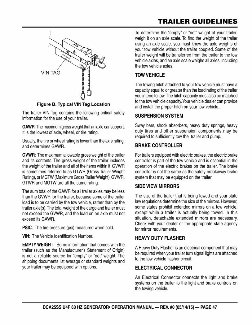
DCA25SSIU4F 60 HZ GENERATOR• OPERATION MANUAL — REV. #0 (05/14/15) — PAGE 47
TRAILER GUIDELINES
Figure B. Typical VIN Tag Location
The trailer VIN Tag contains the following critical safety information for the use of your trailer.
GAWR: The maximum gross weight that an axle cansupport. It is the lowest of axle, wheel, or tire rating.
Usually, the tire or wheel rating is lower than the axle rating, and determines GAWR.
GVWR: The maximum allowable gross weight of the trailer and its contents. The gross weight of the trailer includes the weight of the trailer and all of the items within it. GVWR is sometimes referred to as GTWR (Gross Trailer Weight Rating), or MGTW (Maximum Gross Trailer Weight). GVWR, GTWR and MGTW are all the same rating.
The sum total of the GAWR for all trailer axles may be less than the GVWR for the trailer, because some of the trailer load is to be carried by the tow vehicle, rather than by the trailer axle(s). The total weight of the cargo and trailer must not exceed the GVWR, and the load on an axle must not exceed its GAWR.
PSIC: The tire pressure (psi) measured when cold.
VIN: The Vehicle Identifi cation Number.
EMPTY WEIGHT: Some information that comes with the trailer (such as the Manufacturer’s Statement of Origin) is not a reliable source for “empty” or “net” weight. The shipping documents list average or standard weights and your trailer may be equipped with options.
VIN TAG
VINTAG
To determine the “empty” or “net” weight of your trailer, weigh it on an axle scale. To fi nd the weight of the trailer using an axle scale, you must know the axle weights of your tow vehicle without the trailer coupled. Some of the trailer weight will be transferred from the trailer to the tow vehicle axles, and an axle scale weighs all axles, including the tow vehicle axles.
TOW VEHICLE
The towing hitch attached to your tow vehicle must have a capacity equal to or greater than the load rating of the trailer you intend to tow. The hitch capacity must also be matched to the tow vehicle capacity. Your vehicle dealer can provide and install the proper hitch on your tow vehicle.
SUSPENSION SYSTEM
Sway bars, shock absorbers, heavy duty springs, heavy duty tires and other suspension components may be required to suffi ciently tow the trailer and pump.
BRAKE CONTROLLER
For trailers equipped with electric brakes, the electric brake controller is part of the tow vehicle and is essential in the operation of the electric brakes on the trailer. The brake controller is not the same as the safety breakaway brake system that may be equipped on the trailer.
SIDE VIEW MIRRORS
The size of the trailer that is being towed and your state law regulations determine the size of the mirrors. However, some states prohibit extended mirrors on a tow vehicle, except while a trailer is actually being towed. In this situation, detachable extended mirrors are necessary. Check with your dealer or the appropriate state agency for mirror requirements.
HEAVY DUTY FLASHER
A Heavy Duty Flasher is an electrical component that may be required when your trailer turn signal lights are attached to the tow vehicle fl asher circuit.
ELECTRICAL CONNECTOR
An Electrical Connector connects the light and brake systems on the trailer to the light and brake controls on the towing vehicle.
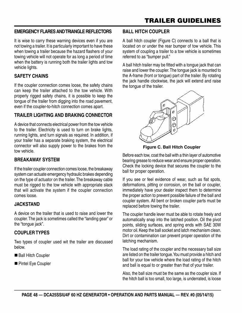
PAGE 48 — DCA25SSIU4F 60 HZ GENERATOR • OPERATION AND PARTS MANUAL — REV. #0 (05/14/15)
TRAILER GUIDELINES
EMERGENCY FLARES AND TRIANGLE REFLECTORS
It is wise to carry these warning devices even if you are not towing a trailer. It is particularly important to have these when towing a trailer because the hazard fl ashers of your towing vehicle will not operate for as long a period of time when the battery is running both the trailer lights and tow vehicle lights.
SAFETY CHAINS
If the coupler connection comes loose, the safety chains can keep the trailer attached to the tow vehicle. With properly rigged safety chains, it is possible to keep the tongue of the trailer from digging into the road pavement, even if the coupler-to-hitch connection comes apart.
TRAILER LIGHTING AND BRAKING CONNECTOR
A device that connects electrical power from the tow vehicle to the trailer. Electricity is used to turn on brake lights, running lights, and turn signals as required. In addition, if your trailer has a separate braking system, the electrical connector will also supply power to the brakes from the tow vehicle.
BREAKAWAY SYSTEM
If the trailer coupler connection comes loose, the breakaway system can actuate emergency hydraulic brakes depending on the type of actuator on the trailer. The breakaway cable must be rigged to the tow vehicle with appropriate slack that will activate the system if the coupler connection comes loose.
JACKSTAND
A device on the trailer that is used to raise and lower the coupler. The jack is sometimes called the “landing gear” or the “tongue jack”.
COUPLER TYPES
Two types of coupler used wit the trailer are discussed below.
�Ball Hitch Coupler
�Pintel Eye Coupler
BALL HITCH COUPLER
A ball hitch coupler (Figure C) connects to a ball that is located on or under the rear bumper of tow vehicle. This system of coupling a trailer to a tow vehicle is sometimes referred to as “bumper pull.”
A ball hitch trailer may be fi tted with a tongue jack that can raise and lower the coupler. The tongue jack is mounted to the A-frame (front or tongue) part of the trailer. By rotating the jack handle clockwise, the jack will extend and raise the tongue of the trailer.
Figure C. Ball Hitch Coupler
Before each tow, coat the ball with a thin layer of automotive bearing grease to reduce wear and ensure proper operation. Check the locking device that secures the coupler to the ball for proper operation.
If you see or feel evidence of wear, such as fl at spots, deformations, pitting or corrosion, on the ball or coupler, immediately have your dealer inspect them to determine the proper action to prevent possible failure of the ball and coupler system. All bent or broken coupler parts must be replaced before towing the trailer.
The coupler handle lever must be able to rotate freely and automatically snap into the latched position. Oil the pivot points, sliding surfaces, and spring ends with SAE 30W motor oil. Keep the ball socket and latch mechanism clean. Dirt or contamination can prevent proper operation of the latching mechanism.
The load rating of the coupler and the necessary ball size are listed on the trailer tongue. You must provide a hitch and ball for your tow vehicle where the load rating of the hitch and ball is equal to or greater than that of your trailer.
Also, the ball size must be the same as the coupler size. If the hitch ball is too small, too large, is underrated, is loose
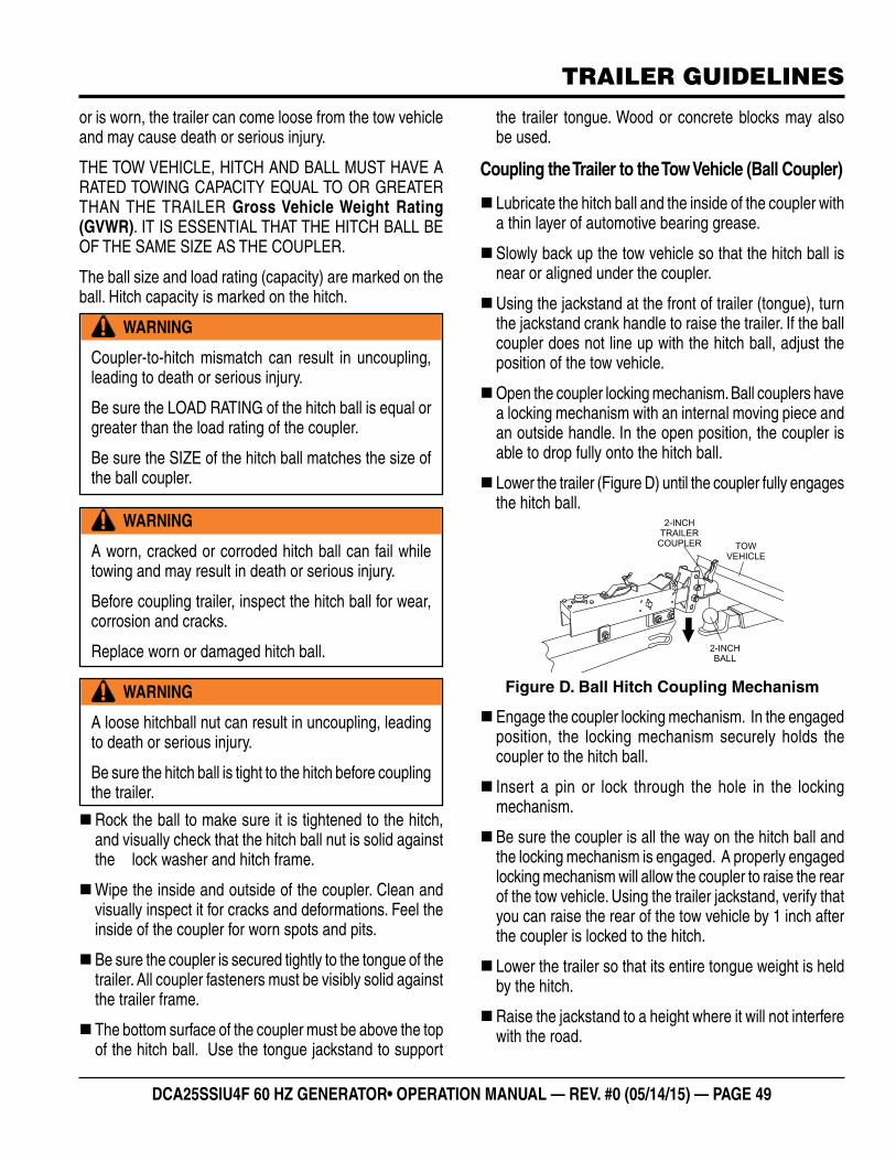
DCA25SSIU4F 60 HZ GENERATOR• OPERATION MANUAL — REV. #0 (05/14/15) — PAGE 49
TRAILER GUIDELINES
or is worn, the trailer can come loose from the tow vehicle and may cause death or serious injury.
THE TOW VEHICLE, HITCH AND BALL MUST HAVE A RATED TOWING CAPACITY EQUAL TO OR GREATER THAN THE TRAILER Gross Vehicle Weight Rating (GVWR). IT IS ESSENTIAL THAT THE HITCH BALL BE OF THE SAME SIZE AS THE COUPLER.
The ball size and load rating (capacity) are marked on the ball. Hitch capacity is marked on the hitch.
�Rock the ball to make sure it is tightened to the hitch, and visually check that the hitch ball nut is solid against the lock washer and hitch frame.
�Wipe the inside and outside of the coupler. Clean and visually inspect it for cracks and deformations. Feel the inside of the coupler for worn spots and pits.
�Be sure the coupler is secured tightly to the tongue of the trailer. All coupler fasteners must be visibly solid against the trailer frame.
� The bottom surface of the coupler must be above the top of the hitch ball. Use the tongue jackstand to support
WARNING
Coupler-to-hitch mismatch can result in uncoupling, leading to death or serious injury.
Be sure the LOAD RATING of the hitch ball is equal or greater than the load rating of the coupler.
Be sure the SIZE of the hitch ball matches the size of the ball coupler.
WARNING
A worn, cracked or corroded hitch ball can fail while towing and may result in death or serious injury.
Before coupling trailer, inspect the hitch ball for wear, corrosion and cracks.
Replace worn or damaged hitch ball.
WARNING
A loose hitchball nut can result in uncoupling, leading to death or serious injury.
Be sure the hitch ball is tight to the hitch before coupling the trailer.
the trailer tongue. Wood or concrete blocks may also be used.
Coupling the Trailer to the Tow Vehicle (Ball Coupler)
� Lubricate the hitch ball and the inside of the coupler with a thin layer of automotive bearing grease.
�Slowly back up the tow vehicle so that the hitch ball is near or aligned under the coupler.
�Using the jackstand at the front of trailer (tongue), turn the jackstand crank handle to raise the trailer. If the ball coupler does not line up with the hitch ball, adjust the position of the tow vehicle.
�Open the coupler locking mechanism. Ball couplers have a locking mechanism with an internal moving piece and an outside handle. In the open position, the coupler is able to drop fully onto the hitch ball.
� Lower the trailer (Figure D) until the coupler fully engages the hitch ball.
Figure D. Ball Hitch Coupling Mechanism
�Engage the coupler locking mechanism. In the engaged position, the locking mechanism securely holds the coupler to the hitch ball.
� Insert a pin or lock through the hole in the locking mechanism.
�Be sure the coupler is all the way on the hitch ball and the locking mechanism is engaged. A properly engaged locking mechanism will allow the coupler to raise the rear of the tow vehicle. Using the trailer jackstand, verify that you can raise the rear of the tow vehicle by 1 inch after the coupler is locked to the hitch.
� Lower the trailer so that its entire tongue weight is held by the hitch.
�Raise the jackstand to a height where it will not interfere with the road.
2-INCHTRAILER
COUPLER
2-INCHBALL
TOWVEHICLE
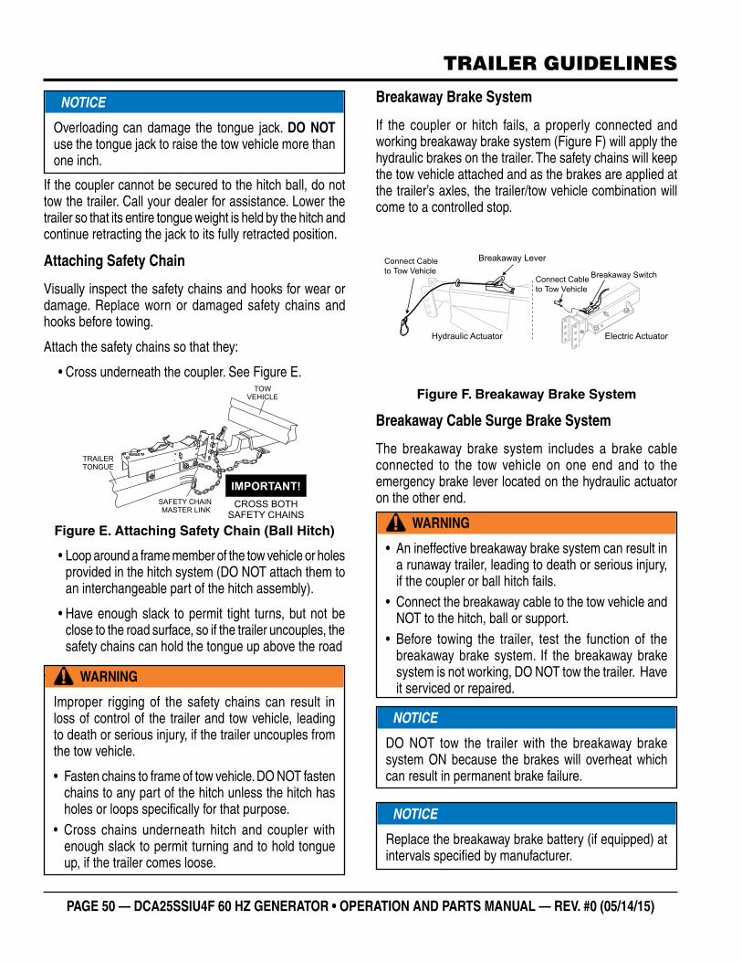
PAGE 50 — DCA25SSIU4F 60 HZ GENERATOR • OPERATION AND PARTS MANUAL — REV. #0 (05/14/15)
TRAILER GUIDELINES
If the coupler cannot be secured to the hitch ball, do not tow the trailer. Call your dealer for assistance. Lower the trailer so that its entire tongue weight is held by the hitch and continue retracting the jack to its fully retracted position.
Attaching Safety Chain
Visually inspect the safety chains and hooks for wear or damage. Replace worn or damaged safety chains and hooks before towing.
Attach the safety chains so that they:
• Cross underneath the coupler. See Figure E.
Figure E. Attaching Safety Chain (Ball Hitch)
• Loop around a frame member of the tow vehicle or holes provided in the hitch system (DO NOT attach them to an interchangeable part of the hitch assembly).
• Have enough slack to permit tight turns, but not be close to the road surface, so if the trailer uncouples, the safety chains can hold the tongue up above the road
.
NOTICE
Overloading can damage the tongue jack. DO NOT use the tongue jack to raise the tow vehicle more than one inch.
CROSS BOTH
SAFETY CHAINS
IMPORTANT!
TRAILER
TONGUE
SAFETY CHAIN
MASTER LINK
TOW
VEHICLE
WARNING
Improper rigging of the safety chains can result in loss of control of the trailer and tow vehicle, leading to death or serious injury, if the trailer uncouples from the tow vehicle.
• Fasten chains to frame of tow vehicle. DO NOT fasten chains to any part of the hitch unless the hitch has holes or loops specifi cally for that purpose.
• Cross chains underneath hitch and coupler with enough slack to permit turning and to hold tongue up, if the trailer comes loose.
Breakaway Brake System
If the coupler or hitch fails, a properly connected and working breakaway brake system (Figure F) will apply the hydraulic brakes on the trailer. The safety chains will keep the tow vehicle attached and as the brakes are applied at the trailer’s axles, the trailer/tow vehicle combination will come to a controlled stop.
Figure F. Breakaway Brake System
Breakaway Cable Surge Brake System
The breakaway brake system includes a brake cable connected to the tow vehicle on one end and to the emergency brake lever located on the hydraulic actuator on the other end.
Breakaway Lever
Connect Cable
to Tow Vehicle
Breakaway Switch
Connect Cable
to Tow Vehicle
Hydraulic Actuator Electric Actuator
WARNING
• An ineffective breakaway brake system can result in a runaway trailer, leading to death or serious injury, if the coupler or ball hitch fails.
• Connect the breakaway cable to the tow vehicle and NOT to the hitch, ball or support.
• Before towing the trailer, test the function of the breakaway brake system. If the breakaway brake system is not working, DO NOT tow the trailer. Have it serviced or repaired.
NOTICE
DO NOT tow the trailer with the breakaway brake system ON because the brakes will overheat which can result in permanent brake failure.
NOTICE
Replace the breakaway brake battery (if equipped) at intervals specifi ed by manufacturer.
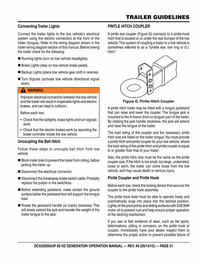
DCA25SSIU4F 60 HZ GENERATOR• OPERATION MANUAL — REV. #0 (05/14/15) — PAGE 51
TRAILER GUIDELINES
Connecting Trailer Lights
Connect the trailer lights to the tow vehicle’s electrical system using the electric connectors at the front of the trailer (tongue). Refer to the wiring diagram shown in the trailer wiring diagram section of this manual. Before towing the trailer check for the following:
�Running lights (turn on tow vehicle headlights).
�Brake Lights (step on tow vehicle brake pedal).
�Backup Lights (place tow vehicle gear shift in reverse).
� Turn Signals (activate tow vehicle directional signal lever).
Uncoupling the Ball Hitch
Follow these steps to uncouple ball hitch from tow vehicle:
�Block trailer tires to prevent the trailer from rolling, before jacking the trailer up.
�Disconnect the electrical connector.
�Disconnect the breakaway brake switch cable. Promptly replace the pullpin in the switchbox.
�Before extending jackstand, make certain the ground surface below the jackstand foot will support the tongue load.
�Rotate the jackstand handle (or crank) clockwise. This will slowly extend the jack and transfer the weight of the trailer tongue to the jack.
WARNING
Improper electrical connection between the tow vehicle and the trailer will result in inoperable lights and electric brakes, and can lead to collision.
Before each tow:
• Check that the taillights, brake lights and turn signals work.
• Check that the electric brakes work by operating the brake controller inside the tow vehicle.
PINTLE HITCH COUPLER
A pintle eye coupler (Figure G) connects to a pintle-hook hitch that is located on or under the rear bumper of the tow vehicle. This system of coupling a trailer to a tow vehicle is sometimes referred to as a “lunette eye, tow ring or G.I. hitch.”
Figure G. Pintle Hitch Coupler
A pintle hitch trailer may be fi tted with a tongue jackstand that can raise and lower the coupler. The tongue jack is mounted to the A-frame (front or tongue) part of the trailer. By rotating the jack handle clockwise, the jack will extend and raise the tongue of the trailer.
The load rating of the coupler and the necessary pintle hitch size are listed on the trailer tongue. You must provide a pintle hitch and pintle coupler for your tow vehicle, where the load rating of the pintle hitch and pintle coupler is equal to or greater than that of your trailer.
Also, the pintle hitch size must be the same as the pintle coupler size. If the hitch is too small, too large, underrated, loose or worn, the trailer can come loose from the tow vehicle, and may cause death or serious injury.
Pintle Coupler and Pintle Hook
Before each tow, check the locking device that secures the coupler to the pintle hook assembly.
The pintle hook lever must be able to operate freely and automatically snap into place into the latched position. Lightly oil the pivot points and sliding surfaces with SAE30W motor oil to prevent rust and help ensure proper operation of the latching mechanism.
If you see or feel evidence of wear, such as fl at spots, deformations, pitting or corrosion, on the pintle hook or coupler, immediately have your dealer inspect them to determine the proper action to prevent possible failure of
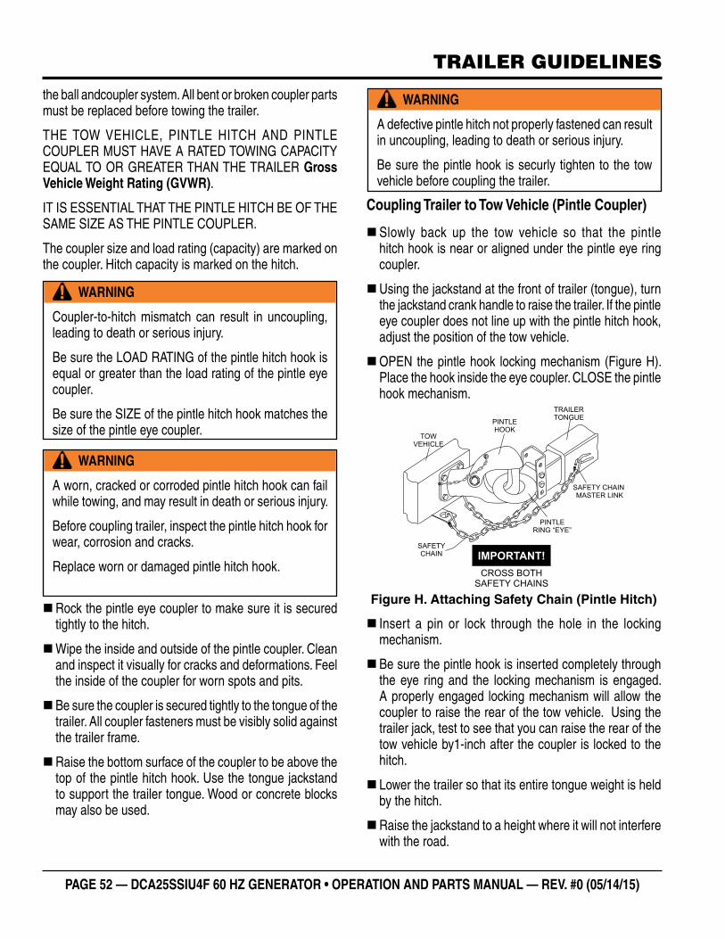
PAGE 52 — DCA25SSIU4F 60 HZ GENERATOR • OPERATION AND PARTS MANUAL — REV. #0 (05/14/15)
TRAILER GUIDELINES
the ball andcoupler system. All bent or broken coupler parts must be replaced before towing the trailer.
THE TOW VEHICLE, PINTLE HITCH AND PINTLE COUPLER MUST HAVE A RATED TOWING CAPACITY EQUAL TO OR GREATER THAN THE TRAILER Gross Vehicle Weight Rating (GVWR).
IT IS ESSENTIAL THAT THE PINTLE HITCH BE OF THE SAME SIZE AS THE PINTLE COUPLER.
The coupler size and load rating (capacity) are marked on the coupler. Hitch capacity is marked on the hitch.
�Rock the pintle eye coupler to make sure it is secured tightly to the hitch.
�Wipe the inside and outside of the pintle coupler. Clean and inspect it visually for cracks and deformations. Feel the inside of the coupler for worn spots and pits.
�Be sure the coupler is secured tightly to the tongue of the trailer. All coupler fasteners must be visibly solid against the trailer frame.
�Raise the bottom surface of the coupler to be above the top of the pintle hitch hook. Use the tongue jackstand to support the trailer tongue. Wood or concrete blocks may also be used.
WARNING
Coupler-to-hitch mismatch can result in uncoupling, leading to death or serious injury.
Be sure the LOAD RATING of the pintle hitch hook is equal or greater than the load rating of the pintle eye coupler.
Be sure the SIZE of the pintle hitch hook matches the size of the pintle eye coupler.
WARNING
A worn, cracked or corroded pintle hitch hook can fail while towing, and may result in death or serious injury.
Before coupling trailer, inspect the pintle hitch hook for wear, corrosion and cracks.
Replace worn or damaged pintle hitch hook.
Coupling Trailer to Tow Vehicle (Pintle Coupler)
�Slowly back up the tow vehicle so that the pintle hitch hook is near or aligned under the pintle eye ring coupler.
�Using the jackstand at the front of trailer (tongue), turn the jackstand crank handle to raise the trailer. If the pintle eye coupler does not line up with the pintle hitch hook, adjust the position of the tow vehicle.
�OPEN the pintle hook locking mechanism (Figure H). Place the hook inside the eye coupler. CLOSE the pintle hook mechanism.
Figure H. Attaching Safety Chain (Pintle Hitch)
� Insert a pin or lock through the hole in the locking mechanism.
�Be sure the pintle hook is inserted completely through the eye ring and the locking mechanism is engaged. A properly engaged locking mechanism will allow the coupler to raise the rear of the tow vehicle. Using the trailer jack, test to see that you can raise the rear of the tow vehicle by1-inch after the coupler is locked to the hitch.
� Lower the trailer so that its entire tongue weight is held by the hitch.
�Raise the jackstand to a height where it will not interfere with the road.
WARNING
A defective pintle hitch not properly fastened can result in uncoupling, leading to death or serious injury.
Be sure the pintle hook is securly tighten to the tow vehicle before coupling the trailer.
TRAILER
TONGUE
SAFETY CHAIN
MASTER LINK
TOW
VEHICLE
CROSS BOTH
SAFETY CHAINS
IMPORTANT!
PINTLE
HOOK
PINTLE
RING “EYE”
SAFETY
CHAIN
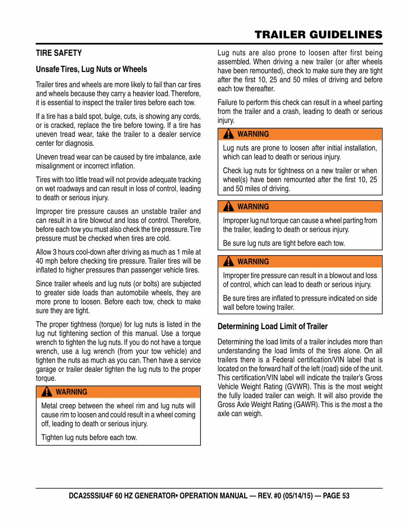
DCA25SSIU4F 60 HZ GENERATOR• OPERATION MANUAL — REV. #0 (05/14/15) — PAGE 53
TRAILER GUIDELINES
TIRE SAFETY
Unsafe Tires, Lug Nuts or Wheels
Trailer tires and wheels are more likely to fail than car tires and wheels because they carry a heavier load. Therefore, it is essential to inspect the trailer tires before each tow.
If a tire has a bald spot, bulge, cuts, is showing any cords, or is cracked, replace the tire before towing. If a tire has uneven tread wear, take the trailer to a dealer service center for diagnosis.
Uneven tread wear can be caused by tire imbalance, axle misalignment or incorrect infl ation.
Tires with too little tread will not provide adequate tracking on wet roadways and can result in loss of control, leading to death or serious injury.
Improper tire pressure causes an unstable trailer and can result in a tire blowout and loss of control. Therefore, before each tow you must also check the tire pressure. Tire pressure must be checked when tires are cold.
Allow 3 hours cool-down after driving as much as 1 mile at 40 mph before checking tire pressure. Trailer tires will be infl ated to higher pressures than passenger vehicle tires.
Since trailer wheels and lug nuts (or bolts) are subjected to greater side loads than automobile wheels, they are more prone to loosen. Before each tow, check to make sure they are tight.
The proper tightness (torque) for lug nuts is listed in the lug nut tightening section of this manual. Use a torque wrench to tighten the lug nuts. If you do not have a torque wrench, use a lug wrench (from your tow vehicle) and tighten the nuts as much as you can. Then have a service garage or trailer dealer tighten the lug nuts to the proper torque.
WARNING
Metal creep between the wheel rim and lug nuts will cause rim to loosen and could result in a wheel coming off, leading to death or serious injury.
Tighten lug nuts before each tow.
Lug nuts are also prone to loosen after first being assembled. When driving a new trailer (or after wheels have been remounted), check to make sure they are tight after the fi rst 10, 25 and 50 miles of driving and before each tow thereafter.
Failure to perform this check can result in a wheel parting from the trailer and a crash, leading to death or serious injury.
Determining Load Limit of Trailer
Determining the load limits of a trailer includes more than understanding the load limits of the tires alone. On all trailers there is a Federal certifi cation/VIN label that is located on the forward half of the left (road) side of the unit. This certifi cation/VIN label will indicate the trailer’s Gross Vehicle Weight Rating (GVWR). This is the most weight the fully loaded trailer can weigh. It will also provide the Gross Axle Weight Rating (GAWR). This is the most a the axle can weigh.
WARNING
Lug nuts are prone to loosen after initial installation, which can lead to death or serious injury.
Check lug nuts for tightness on a new trailer or when wheel(s) have been remounted after the fi rst 10, 25 and 50 miles of driving.
WARNING
Improper lug nut torque can cause a wheel parting from the trailer, leading to death or serious injury.
Be sure lug nuts are tight before each tow.
WARNING
Improper tire pressure can result in a blowout and loss of control, which can lead to death or serious injury.
Be sure tires are infl ated to pressure indicated on side wall before towing trailer.
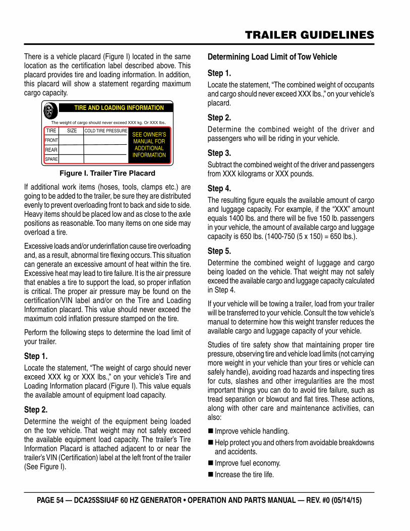
PAGE 54 — DCA25SSIU4F 60 HZ GENERATOR • OPERATION AND PARTS MANUAL — REV. #0 (05/14/15)
TRAILER GUIDELINES
There is a vehicle placard (Figure I) located in the same location as the certifi cation label described above. This placard provides tire and loading information. In addition, this placard will show a statement regarding maximum cargo capacity.
Figure I. Trailer Tire Placard
If additional work items (hoses, tools, clamps etc.) are going to be added to the trailer, be sure they are distributed evenly to prevent overloading front to back and side to side. Heavy items should be placed low and as close to the axle positions as reasonable. Too many items on one side may overload a tire.
Excessive loads and/or underinfl ation cause tire overloading and, as a result, abnormal tire fl exing occurs. This situation can generate an excessive amount of heat within the tire. Excessive heat may lead to tire failure. It is the air pressure that enables a tire to support the load, so proper infl ation is critical. The proper air pressure may be found on the certifi cation/VIN label and/or on the Tire and Loading Information placard. This value should never exceed the maximum cold infl ation pressure stamped on the tire.
Perform the following steps to determine the load limit of your trailer.
Step 1.Locate the statement, “The weight of cargo should never exceed XXX kg or XXX lbs.,” on your vehicle’s Tire and Loading Information placard (Figure I). This value equals the available amount of equipment load capacity.
Step 2.Determine the weight of the equipment being loaded on the tow vehicle. That weight may not safely exceed the available equipment load capacity. The trailer’s Tire Information Placard is attached adjacent to or near the trailer’s VIN (Certifi cation) label at the left front of the trailer (See Figure I).
The weight of cargo should never exceed XXX kg. Or XXX lbs.
TIRE
FRONT
REAR
SPARE
SIZE COLD TIRE PRESSURE
TIRE AND LOADING INFORMATION
SEE OWNER’SMANUAL FORADDITIONAL
INFORMATION
Determining Load Limit of Tow Vehicle
Step 1.Locate the statement, “The combined weight of occupants and cargo should never exceed XXX lbs.,” on your vehicle’s placard.
Step 2.Determine the combined weight of the driver and passengers who will be riding in your vehicle.
Step 3.Subtract the combined weight of the driver and passengers from XXX kilograms or XXX pounds.
Step 4.The resulting fi gure equals the available amount of cargo and luggage capacity. For example, if the “XXX” amount equals 1400 lbs. and there will be fi ve 150 lb. passengers in your vehicle, the amount of available cargo and luggage capacity is 650 lbs. (1400-750 (5 x 150) = 650 lbs.).
Step 5.Determine the combined weight of luggage and cargo being loaded on the vehicle. That weight may not safely exceed the available cargo and luggage capacity calculated in Step 4.
If your vehicle will be towing a trailer, load from your trailer will be transferred to your vehicle. Consult the tow vehicle’s manual to determine how this weight transfer reduces the available cargo and luggage capacity of your vehicle.
Studies of tire safety show that maintaining proper tire pressure, observing tire and vehicle load limits (not carrying more weight in your vehicle than your tires or vehicle can safely handle), avoiding road hazards and inspecting tires for cuts, slashes and other irregularities are the most important things you can do to avoid tire failure, such as tread separation or blowout and fl at tires. These actions, along with other care and maintenance activities, can also:
� Improve vehicle handling. �Help protect you and others from avoidable breakdowns and accidents. � Improve fuel economy. � Increase the tire life.
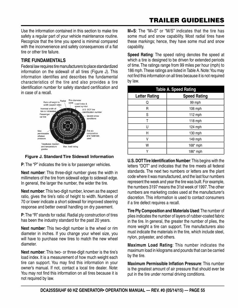
DCA25SSIU4F 60 HZ GENERATOR• OPERATION MANUAL — REV. #0 (05/14/15) — PAGE 55
TRAILER GUIDELINES
Use the information contained in this section to make tire safety a regular part of your vehicle maintenance routine. Recognize that the time you spend is minimal compared with the inconvenience and safety consequences of a fl at tire or other tire failure.
TIRE FUNDAMENTALSFederal law requires tire manufacturers to place standardized information on the sidewall of all tires (Figure J). This information identifies and describes the fundamental characteristics of the tire and also provides a tire identifi cation number for safety standard certifi cation and in case of a recall.
Figure J. Standard Tire Sidewall Information
P: The “P” indicates the tire is for passenger vehicles.
Next number: This three-digit number gives the width in millimeters of the tire from sidewall edge to sidewall edge. In general, the larger the number, the wider the tire.
Next number: This two-digit number, known as the aspect ratio, gives the tire’s ratio of height to width. Numbers of 70 or lower indicate a short sidewall for improved steering response and better overall handling on dry pavement.
P: The “R” stands for radial. Radial ply construction of tires has been the industry standard for the past 20 years.
Next number: This two-digit number is the wheel or rim diameter in inches. If you change your wheel size, you will have to purchase new tires to match the new wheel diameter.
Next number: This two- or three-digit number is the tire’s load index. It is a measurement of how much weight each tire can support. You may fi nd this information in your owner’s manual. If not, contact a local tire dealer. Note: You may not fi nd this information on all tires because it is not required by law.
M+S: The “M+S” or “M/S” indicates that the tire has some mud and snow capability. Most radial tires have these markings; hence, they have some mud and snow capability.
Speed Rating: The speed rating denotes the speed at which a tire is designed to be driven for extended periods of time. The ratings range from 99 miles per hour (mph) to 186 mph. These ratings are listed in Table A. Note: You may not fi nd this information on all tires because it is not required by law.
U.S. DOT Tire Identifi cation Number: This begins with the letters “DOT” and indicates that the tire meets all federal standards. The next two numbers or letters are the plant code where it was manufactured, and the last four numbers represent the week and year the tire was built. For example, the numbers 3197 means the 31st week of 1997. The other numbers are marketing codes used at the manufacturer’s discretion. This information is used to contact consumers if a tire defect requires a recall.
Tire Ply Composition and Materials Used: The number of plies indicates the number of layers of rubber-coated fabric in the tire. In general, the greater the number of plies, the more weight a tire can support. Tire manufacturers also must indicate the materials in the tire, which include steel, nylon, polyester, and others.
Maximum Load Rating: This number indicates the maximum load in kilograms and pounds that can be carried by the tire.
Maximum Permissible Infl ation Pressure: This number is the greatest amount of air pressure that should ever be put in the tire under normal driving conditions.
Table A. Speed RatingLetter Rating Speed Rating
Q 99 mph
R 106 mph
S 112 mph
T 118 mph
U 124 mph
H 130 mph
V 149 mph
W 168* mph
Y 186* mph
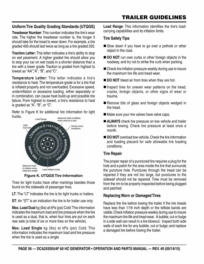
PAGE 56 — DCA25SSIU4F 60 HZ GENERATOR • OPERATION AND PARTS MANUAL — REV. #0 (05/14/15)
TRAILER GUIDELINES
Uniform Tire Quality Grading Standards (UTQGS)Treadwear Number: This number indicates the tire’s wear rate. The higher the treadwear number is, the longer it should take for the tread to wear down. For example, a tire graded 400 should last twice as long as a tire graded 200.
Traction Letter: This letter indicates a tire’s ability to stop on wet pavement. A higher graded tire should allow you to stop your car on wet roads in a shorter distance than a tire with a lower grade. Traction is graded from highest to lowest as “AA”,”A”, “B”, and “C”.
Temperature Letter: This letter indicates a tire’s resistance to heat. The temperature grade is for a tire that is infl ated properly and not overloaded. Excessive speed, underinfl ation or excessive loading, either separately or in combination, can cause heat build-up and possible tire failure. From highest to lowest, a tire’s resistance to heat is graded as “A”, “B”, or “C”.
Refer to Figure K for additional tire information for light trucks.
Figure K. UTQGS Tire Information
Tires for light trucks have other markings besides those found on the sidewalls of passenger tires.
LT: The “LT” indicates the tire is for light trucks or trailers.
ST: An “ST” is an indication the tire is for trailer use only.
Max. Load Dual kg (lbs) at kPa (psi) Cold: This information indicates the maximum load and tire pressure when the tire is used as a dual, that is, when four tires are put on each rear axle (a total of six or more tires on the vehicle).
Max. Load Single kg (lbs) at kPa (psi) Cold: This information indicates the maximum load and tire pressure when the tire is used as a single.
Load Range: This information identifi es the tire’s load-carrying capabilities and its infl ation limits.
Tire Safety Tips
�Slow down if you have to go over a pothole or other object in the road.
�DO NOT run over curbs or other foreign objects in the roadway, and try not to strike the curb when parking.
�Check tire infl ation pressure weekly during use to insure the maximum tire life and tread wear.
�DO NOT bleed air from tires when they are hot.
� Inspect tires for uneven wear patterns on the tread, cracks, foreign objects, or other signs of wear or trauma.
�Remove bits of glass and foreign objects wedged in the tread.
�Make sure your tire valves have valve caps.
�ALWAYS check tire pressure on tow vehicle and trailer before towing. Check tire pressure at least once a month.
�DO NOT overload tow vehicle. Check the tire information and loading placard for safe allowable tire loading conditions.
Tire Repair
The proper repair of a punctured tire requires a plug for the hole and a patch for the area inside the tire that surrounds the puncture hole. Punctures through the tread can be repaired if they are not too large, but punctures to the sidewall should not be repaired. Tires must be removed from the rim to be properly inspected before being plugged and patched.
Replacing Worn or Damaged Tires
Replace the tire before towing the trailer if the tire treads have less than 1/16 inch depth or the telltale bands are visible. Check infl ation pressure weekly during use to insure the maximum tire life and tread wear. A bubble, cut or bulge in a side wall can result in a tire blowout. Inspect both side walls of each tire for any bubble, cut or bulge; and replace a damaged tire before towing the trailer.
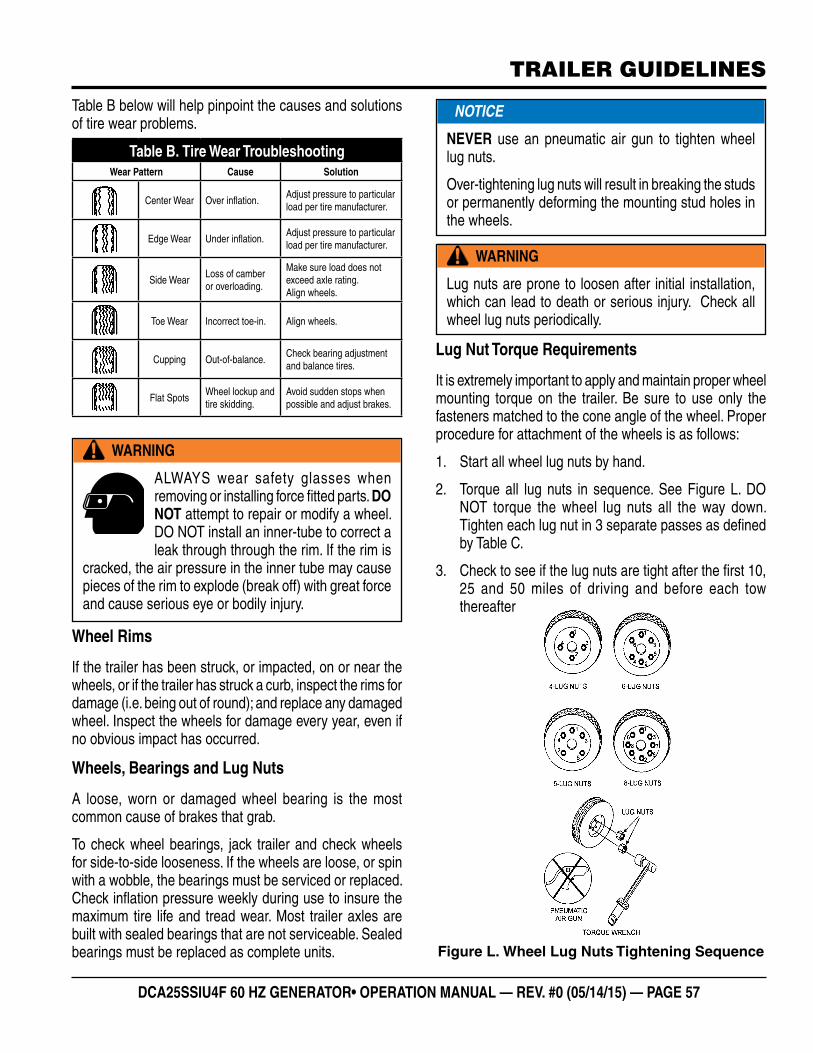
DCA25SSIU4F 60 HZ GENERATOR• OPERATION MANUAL — REV. #0 (05/14/15) — PAGE 57
TRAILER GUIDELINES
Table B below will help pinpoint the causes and solutions of tire wear problems.
Wheel Rims
If the trailer has been struck, or impacted, on or near the wheels, or if the trailer has struck a curb, inspect the rims for damage (i.e. being out of round); and replace any damaged wheel. Inspect the wheels for damage every year, even if no obvious impact has occurred.
Wheels, Bearings and Lug Nuts
A loose, worn or damaged wheel bearing is the most common cause of brakes that grab.
To check wheel bearings, jack trailer and check wheels for side-to-side looseness. If the wheels are loose, or spin with a wobble, the bearings must be serviced or replaced. Check infl ation pressure weekly during use to insure the maximum tire life and tread wear. Most trailer axles are built with sealed bearings that are not serviceable. Sealed bearings must be replaced as complete units.
Table B. Tire Wear TroubleshootingWear Pattern Cause Solution
Center Wear Over infl ation.Adjust pressure to particular load per tire manufacturer.
Edge Wear Under infl ation.Adjust pressure to particular load per tire manufacturer.
Side WearLoss of camberor overloading.
Make sure load does not exceed axle rating. Align wheels.
Toe Wear Incorrect toe-in. Align wheels.
Cupping Out-of-balance.Check bearing adjustment and balance tires.
Flat SpotsWheel lockup andtire skidding.
Avoid sudden stops when possible and adjust brakes.
WARNING
ALWAYS wear safety glasses when removing or installing force fi tted parts. DO NOT attempt to repair or modify a wheel. DO NOT install an inner-tube to correct a leak through through the rim. If the rim is
cracked, the air pressure in the inner tube may cause pieces of the rim to explode (break off) with great force and cause serious eye or bodily injury.
Lug Nut Torque Requirements
It is extremely important to apply and maintain proper wheel mounting torque on the trailer. Be sure to use only the fasteners matched to the cone angle of the wheel. Proper procedure for attachment of the wheels is as follows:
1. Start all wheel lug nuts by hand.
2. Torque all lug nuts in sequence. See Figure L. DO NOT torque the wheel lug nuts all the way down. Tighten each lug nut in 3 separate passes as defi ned by Table C.
3. Check to see if the lug nuts are tight after the fi rst 10, 25 and 50 miles of driving and before each tow thereafter
Figure L. Wheel Lug Nuts Tightening Sequence
WARNING
Lug nuts are prone to loosen after initial installation, which can lead to death or serious injury. Check all wheel lug nuts periodically.
NOTICE
NEVER use an pneumatic air gun to tighten wheel lug nuts.
Over-tightening lug nuts will result in breaking the studs or permanently deforming the mounting stud holes in the wheels.
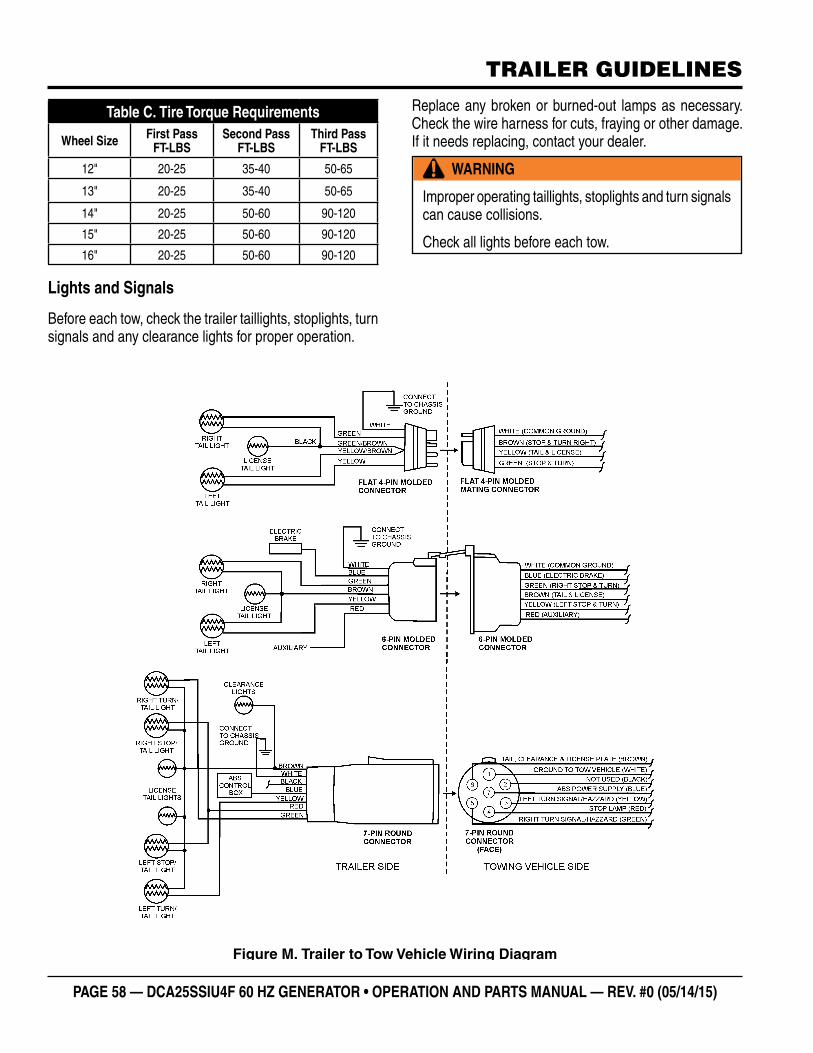
PAGE 58 — DCA25SSIU4F 60 HZ GENERATOR • OPERATION AND PARTS MANUAL — REV. #0 (05/14/15)
TRAILER GUIDELINES
Lights and Signals
Before each tow, check the trailer taillights, stoplights, turn signals and any clearance lights for proper operation.
Table C. Tire Torque Requirements
Wheel Size First PassFT-LBS
Second PassFT-LBS
Third PassFT-LBS
12" 20-25 35-40 50-65
13" 20-25 35-40 50-65
14" 20-25 50-60 90-120
15" 20-25 50-60 90-120
16" 20-25 50-60 90-120
Replace any broken or burned-out lamps as necessary. Check the wire harness for cuts, fraying or other damage. If it needs replacing, contact your dealer.
WARNING
Improper operating taillights, stoplights and turn signals can cause collisions.
Check all lights before each tow.
Figure M. Trailer to Tow Vehicle Wiring Diagram

DCA25SSIU4F 60 HZ GENERATOR• OPERATION MANUAL — REV. #0 (05/14/15) — PAGE 59
NOTES
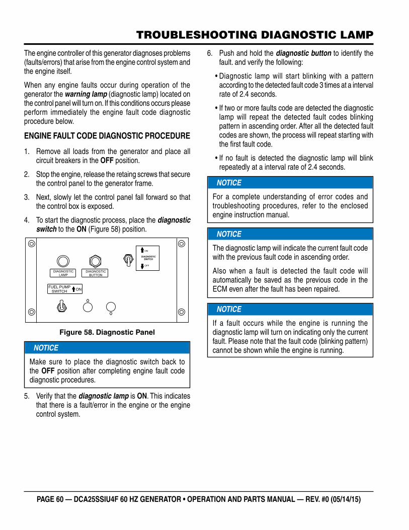
PAGE 60 — DCA25SSIU4F 60 HZ GENERATOR • OPERATION AND PARTS MANUAL — REV. #0 (05/14/15)
TROUBLESHOOTING DIAGNOSTIC LAMP
The engine controller of this generator diagnoses problems (faults/errors) that arise from the engine control system and the engine itself.
When any engine faults occur during operation of the generator the warning lamp (diagnostic lamp) located on the control panel will turn on. If this conditions occurs please perform immediately the engine fault code diagnostic procedure below.
ENGINE FAULT CODE DIAGNOSTIC PROCEDURE
1. Remove all loads from the generator and place all circuit breakers in the OFF position.
2. Stop the engine, release the retaing screws that secure the control panel to the generator frame.
3. Next, slowly let the control panel fall forward so that the control box is exposed.
4. To start the diagnostic process, place the diagnostic switch to the ON (Figure 58) position.
Figure 58. Diagnostic Panel
5. Verify that the diagnostic lamp is ON. This indicates that there is a fault/error in the engine or the engine control system.
DIAGNOSTICLAMP
DIAGNOSTICBUTTON
DIAGNOSTIC
SWITCH
ON
OFF
FUEL PUMPSWITCH
ON
NOTICE
Make sure to place the diagnostic switch back to the OFF position after completing engine fault code diagnostic procedures.
6. Push and hold the diagnostic button to identify the fault. and verify the following:
• Diagnostic lamp will start blinking with a pattern according to the detected fault code 3 times at a interval rate of 2.4 seconds.
• If two or more faults code are detected the diagnostic lamp will repeat the detected fault codes blinking pattern in ascending order. After all the detected fault codes are shown, the process will repeat starting with the first fault code.
• If no fault is detected the diagnostic lamp will blink repeatedly at a interval rate of 2.4 seconds.
NOTICE
For a complete understanding of error codes and troubleshooting procedures, refer to the enclosed engine instruction manual.
NOTICE
The diagnostic lamp will indicate the current fault code with the previous fault code in ascending order.
Also when a fault is detected the fault code will automatically be saved as the previous code in the ECM even after the fault has been repaired.
NOTICE
If a fault occurs while the engine is running the diagnostic lamp will turn on indicating only the current fault. Please note that the fault code (blinking pattern) cannot be shown while the engine is running.
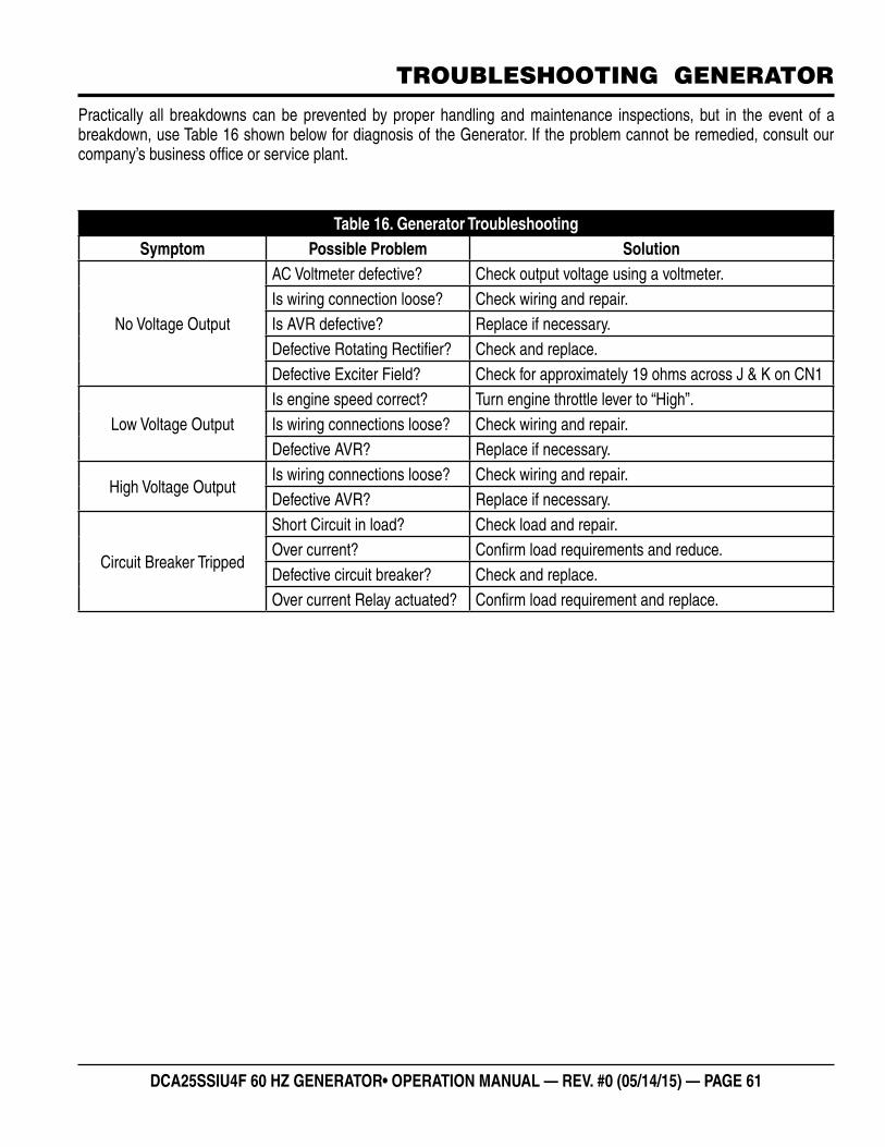
DCA25SSIU4F 60 HZ GENERATOR• OPERATION MANUAL — REV. #0 (05/14/15) — PAGE 61
Table 16. Generator TroubleshootingSymptom Possible Problem Solution
No Voltage Output
AC Voltmeter defective? Check output voltage using a voltmeter.Is wiring connection loose? Check wiring and repair.Is AVR defective? Replace if necessary.Defective Rotating Rectifier? Check and replace.Defective Exciter Field? Check for approximately 19 ohms across J & K on CN1
Low Voltage OutputIs engine speed correct? Turn engine throttle lever to “High”.Is wiring connections loose? Check wiring and repair.Defective AVR? Replace if necessary.
High Voltage OutputIs wiring connections loose? Check wiring and repair.Defective AVR? Replace if necessary.
Circuit Breaker Tripped
Short Circuit in load? Check load and repair.Over current? Confirm load requirements and reduce.Defective circuit breaker? Check and replace.Over current Relay actuated? Confirm load requirement and replace.
Practically all breakdowns can be prevented by proper handling and maintenance inspections, but in the event of a breakdown, use Table 16 shown below for diagnosis of the Generator. If the problem cannot be remedied, consult our company’s business office or service plant.
TROUBLESHOOTING GENERATOR
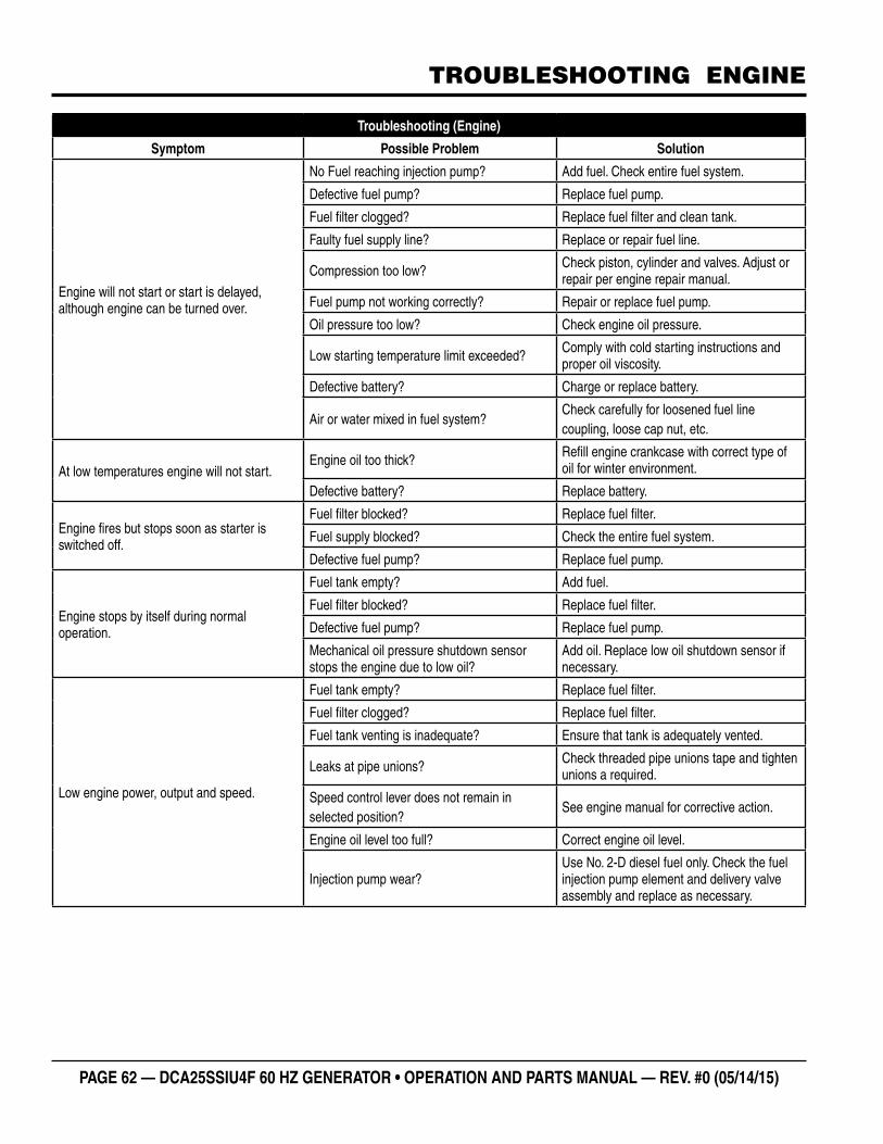
PAGE 62 — DCA25SSIU4F 60 HZ GENERATOR • OPERATION AND PARTS MANUAL — REV. #0 (05/14/15)
TROUBLESHOOTING ENGINE
Troubleshooting (Engine)
Symptom Possible Problem Solution
Engine will not start or start is delayed, although engine can be turned over.
No Fuel reaching injection pump? Add fuel. Check entire fuel system.
Defective fuel pump? Replace fuel pump.
Fuel fi lter clogged? Replace fuel fi lter and clean tank.
Faulty fuel supply line? Replace or repair fuel line.
Compression too low? Check piston, cylinder and valves. Adjust or repair per engine repair manual.
Fuel pump not working correctly? Repair or replace fuel pump.
Oil pressure too low? Check engine oil pressure.
Low starting temperature limit exceeded? Comply with cold starting instructions and proper oil viscosity.
Defective battery? Charge or replace battery.
Air or water mixed in fuel system?Check carefully for loosened fuel line coupling, loose cap nut, etc.
At low temperatures engine will not start.Engine oil too thick? Refi ll engine crankcase with correct type of
oil for winter environment.
Defective battery? Replace battery.
Engine fi res but stops soon as starter is switched off.
Fuel fi lter blocked? Replace fuel fi lter.
Fuel supply blocked? Check the entire fuel system.
Defective fuel pump? Replace fuel pump.
Engine stops by itself during normal operation.
Fuel tank empty? Add fuel.
Fuel fi lter blocked? Replace fuel fi lter.
Defective fuel pump? Replace fuel pump.
Mechanical oil pressure shutdown sensor stops the engine due to low oil?
Add oil. Replace low oil shutdown sensor if necessary.
Low engine power, output and speed.
Fuel tank empty? Replace fuel fi lter.
Fuel fi lter clogged? Replace fuel fi lter.
Fuel tank venting is inadequate? Ensure that tank is adequately vented.
Leaks at pipe unions? Check threaded pipe unions tape and tighten unions a required.
Speed control lever does not remain in selected position?
See engine manual for corrective action.
Engine oil level too full? Correct engine oil level.
Injection pump wear?Use No. 2-D diesel fuel only. Check the fuel injection pump element and delivery valve assembly and replace as necessary.
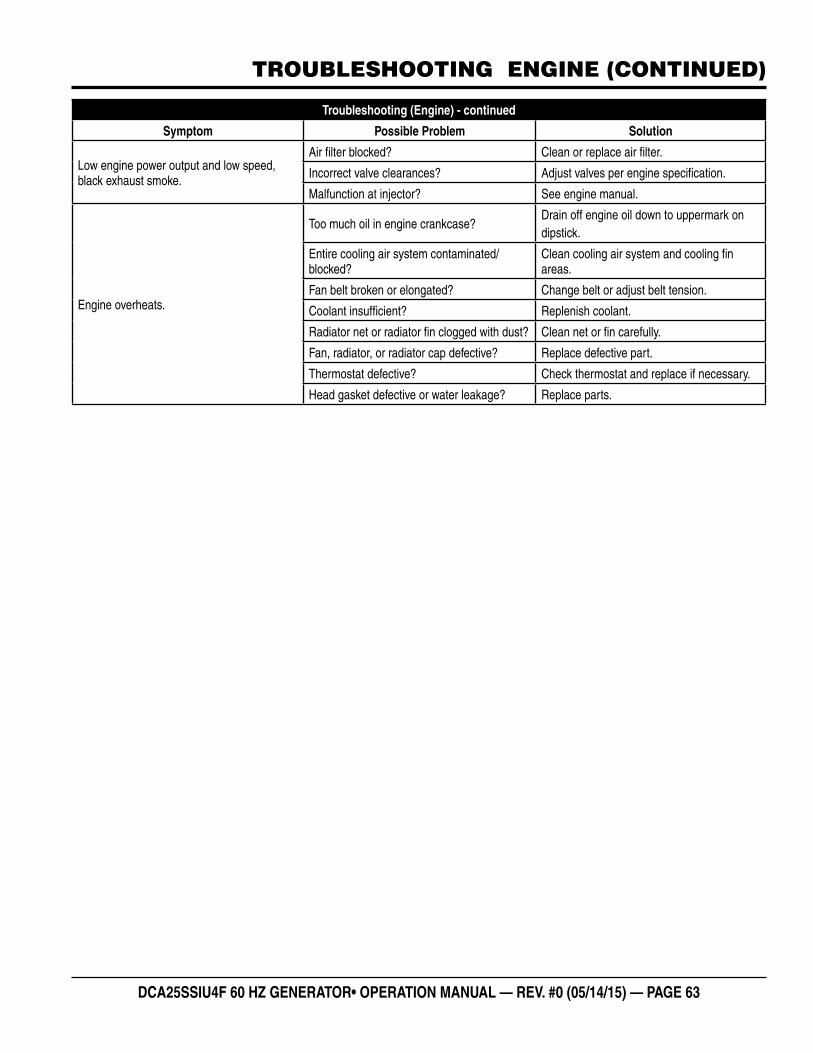
DCA25SSIU4F 60 HZ GENERATOR• OPERATION MANUAL — REV. #0 (05/14/15) — PAGE 63
Troubleshooting (Engine) - continued
Symptom Possible Problem Solution
Low engine power output and low speed, black exhaust smoke.
Air fi lter blocked? Clean or replace air fi lter.
Incorrect valve clearances? Adjust valves per engine specifi cation.
Malfunction at injector? See engine manual.
Engine overheats.
Too much oil in engine crankcase?Drain off engine oil down to uppermark on dipstick.
Entire cooling air system contaminated/blocked?
Clean cooling air system and cooling fi n areas.
Fan belt broken or elongated? Change belt or adjust belt tension.
Coolant insuffi cient? Replenish coolant.
Radiator net or radiator fi n clogged with dust? Clean net or fi n carefully.
Fan, radiator, or radiator cap defective? Replace defective part.
Thermostat defective? Check thermostat and replace if necessary.
Head gasket defective or water leakage? Replace parts.
TROUBLESHOOTING ENGINE (CONTINUED)
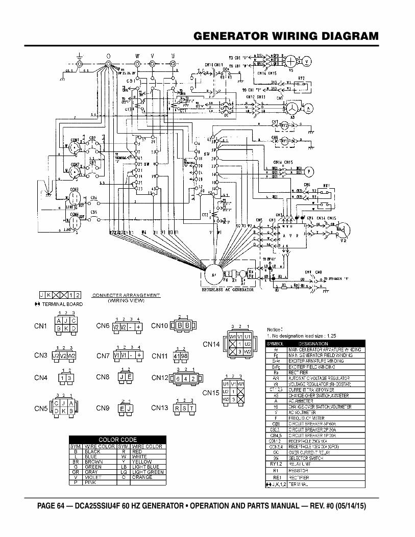
PAGE 64 — DCA25SSIU4F 60 HZ GENERATOR • OPERATION AND PARTS MANUAL — REV. #0 (05/14/15)
GENERATOR WIRING DIAGRAM
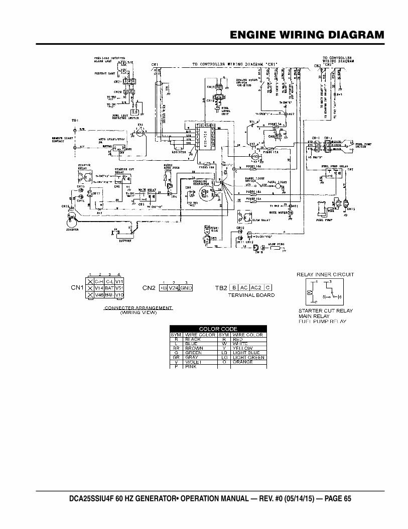
DCA25SSIU4F 60 HZ GENERATOR• OPERATION MANUAL — REV. #0 (05/14/15) — PAGE 65
ENGINE WIRING DIAGRAM
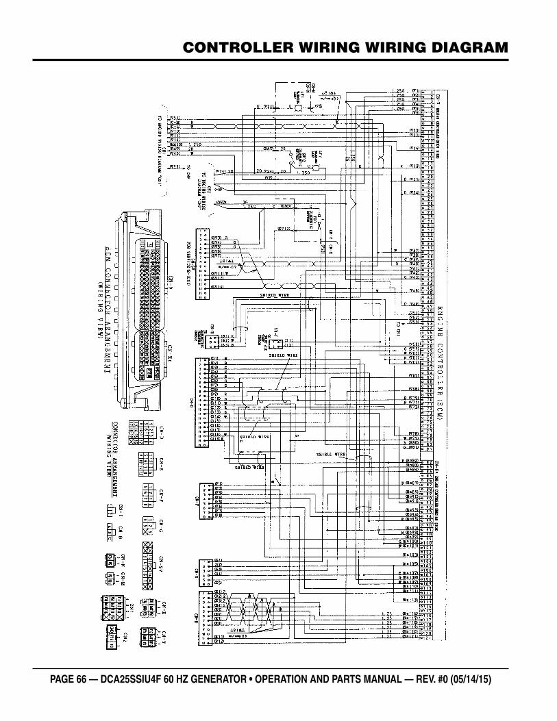
PAGE 66 — DCA25SSIU4F 60 HZ GENERATOR • OPERATION AND PARTS MANUAL — REV. #0 (05/14/15)
CONTROLLER WIRING WIRING DIAGRAM
DCA25SSIU4F 60 HZ GENERATOR• OPERATION MANUAL — REV. #0 (05/14/15) — PAGE 67
NOTES
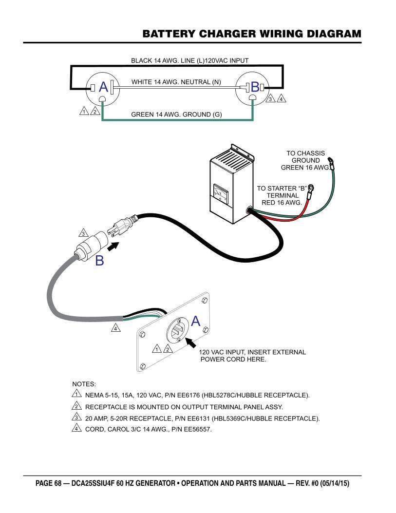
PAGE 68 — DCA25SSIU4F 60 HZ GENERATOR • OPERATION AND PARTS MANUAL — REV. #0 (05/14/15)
BATTERY CHARGER WIRING DIAGRAM
TO STARTER “B”TERMINAL
RED 16 AWG.
TO CHASSISGROUND
GREEN 16 AWG.
NEMA 5-15, 15A, 120 VAC, P/N EE6176 (HBL5278C/HUBBLE RECEPTACLE).
NOTES:
1
2 RECEPTACLE IS MOUNTED ON OUTPUT TERMINAL PANEL ASSY.
20 AMP, 5-20R RECEPTACLE, P/N EE6131 (HBL5369C/HUBBLE RECEPTACLE).3
4 CORD, CAROL 3/C 14 AWG., P/N EE56557.
120 VAC INPUT, INSERT EXTERNALPOWER CORD HERE.
3
1 2
4
BLACK 14 AWG. LINE (L)120VAC INPUT
WHITE 14 AWG. NEUTRAL (N)
GREEN 14 AWG. GROUND (G)1 2
3 4
A
B
A B
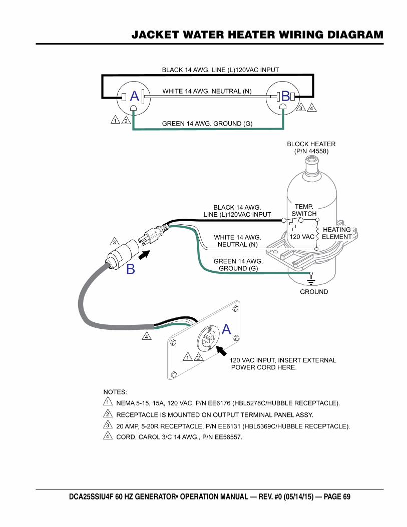
DCA25SSIU4F 60 HZ GENERATOR• OPERATION MANUAL — REV. #0 (05/14/15) — PAGE 69
JACKET WATER HEATER WIRING DIAGRAM
NEMA 5-15, 15A, 120 VAC, P/N EE6176 (HBL5278C/HUBBLE RECEPTACLE).
BLACK 14 AWG.LINE (L)120VAC INPUT
WHITE 14 AWG.NEUTRAL (N)
GREEN 14 AWG.GROUND (G)
NOTES:
1
2 RECEPTACLE IS MOUNTED ON OUTPUT TERMINAL PANEL ASSY.
20 AMP, 5-20R RECEPTACLE, P/N EE6131 (HBL5369C/HUBBLE RECEPTACLE).3
GROUND
120 VAC
4 CORD, CAROL 3/C 14 AWG., P/N EE56557.
BLOCK HEATER(P/N 44558)
120 VAC INPUT, INSERT EXTERNALPOWER CORD HERE.
3
1 2
4
HEATINGELEMENT
TEMP.SWITCH
BLACK 14 AWG. LINE (L)120VAC INPUT
WHITE 14 AWG. NEUTRAL (N)
GREEN 14 AWG. GROUND (G)1 2
3 4
A
B
A B
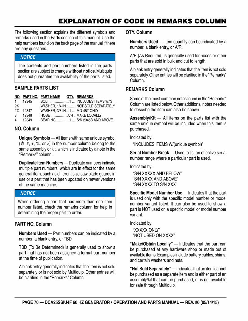
PAGE 70 — DCA25SSIU4F 60 HZ GENERATOR • OPERATION AND PARTS MANUAL — REV. #0 (05/14/15)
EXPLANATION OF CODE IN REMARKS COLUMN
The following section explains the different symbols and remarks used in the Parts section of this manual. Use the help numbers found on the back page of the manual if there are any questions.
SAMPLE PARTS LIST
NO. PART NO. PART NAME QTY. REMARKS1 12345 BOLT .....................1 .....INCLUDES ITEMS W/%2% WASHER, 1/4 IN. ..........NOT SOLD SEPARATELY2% 12347 WASHER, 3/8 IN. ..1 .....MQ-45T ONLY3 12348 HOSE ..................A/R ...MAKE LOCALLY4 12349 BEARING ..............1 .....S/N 2345B AND ABOVE
NO. Column
Unique Symbols — All items with same unique symbol (@, #, +, %, or >) in the number column belong to the same assembly or kit, which is indicated by a note in the “Remarks” column.
Duplicate Item Numbers — Duplicate numbers indicate multiple part numbers, which are in effect for the same general item, such as different size saw blade guards in use or a part that has been updated on newer versions of the same machine.
PART NO. Column
Numbers Used — Part numbers can be indicated by a number, a blank entry, or TBD.
TBD (To Be Determined) is generally used to show a part that has not been assigned a formal part number at the time of publication.
A blank entry generally indicates that the item is not sold separately or is not sold by Multiquip. Other entries will be clarifi ed in the “Remarks” Column.
NOTICE
The contents and part numbers listed in the parts section are subject to change without notice. Multiquip does not guarantee the availability of the parts listed.
NOTICE
When ordering a part that has more than one item number listed, check the remarks column for help in determining the proper part to order.
QTY. Column
Numbers Used — Item quantity can be indicated by a number, a blank entry, or A/R.
A/R (As Required) is generally used for hoses or other parts that are sold in bulk and cut to length.
A blank entry generally indicates that the item is not sold separately. Other entries will be clarifi ed in the “Remarks” Column.
REMARKS Column
Some of the most common notes found in the “Remarks” Column are listed below. Other additional notes needed to describe the item can also be shown.
Assembly/Kit — All items on the parts list with the same unique symbol will be included when this item is purchased.
Indicated by:“INCLUDES ITEMS W/(unique symbol)”
Serial Number Break — Used to list an effective serial number range where a particular part is used.
Indicated by: “S/N XXXXX AND BELOW”“S/N XXXX AND ABOVE”“S/N XXXX TO S/N XXX”
Specifi c Model Number Use — Indicates that the part is used only with the specifi c model number or model number variant listed. It can also be used to show a part is NOT used on a specifi c model or model number variant.
Indicated by:“XXXXX ONLY”“NOT USED ON XXXX”
“Make/Obtain Locally” — Indicates that the part can be purchased at any hardware shop or made out of available items. Examples include battery cables, shims, and certain washers and nuts.
“Not Sold Separately” — Indicates that an item cannot be purchased as a separate item and is either part of an assembly/kit that can be purchased, or is not available for sale through Multiquip.
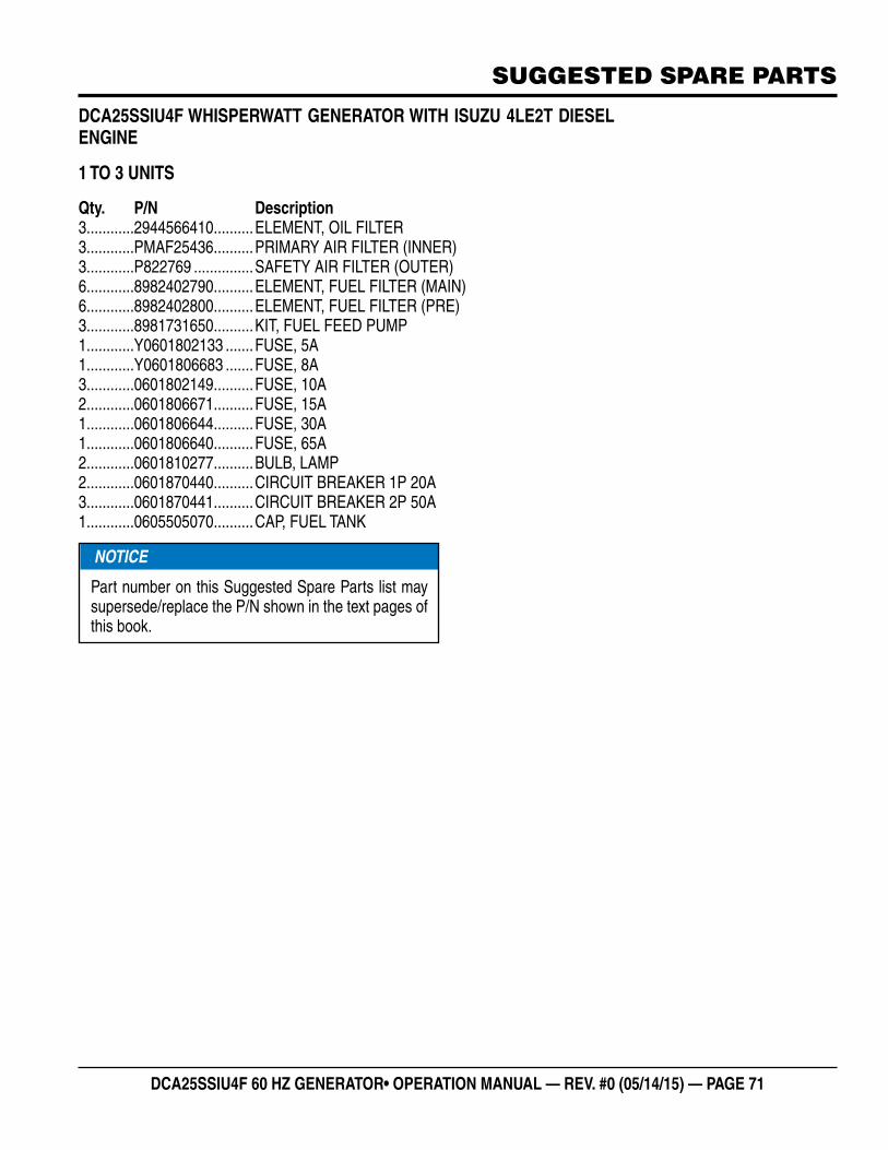
DCA25SSIU4F 60 HZ GENERATOR• OPERATION MANUAL — REV. #0 (05/14/15) — PAGE 71
SUGGESTED SPARE PARTS
DCA25SSIU4F WHISPERWATT GENERATOR WITH ISUZU 4LE2T DIESEL ENGINE
1 TO 3 UNITS
Qty. P/N Description3............2944566410 ..........ELEMENT, OIL FILTER3............PMAF25436 ..........PRIMARY AIR FILTER (INNER)3............P822769 ...............SAFETY AIR FILTER (OUTER)6............8982402790 ..........ELEMENT, FUEL FILTER (MAIN)6............8982402800 ..........ELEMENT, FUEL FILTER (PRE)3............8981731650 ..........KIT, FUEL FEED PUMP1............Y0601802133 .......FUSE, 5A1............Y0601806683 .......FUSE, 8A3............0601802149 ..........FUSE, 10A2............0601806671 ..........FUSE, 15A1............0601806644 ..........FUSE, 30A1............0601806640 ..........FUSE, 65A2............0601810277 ..........BULB, LAMP2............0601870440 ..........CIRCUIT BREAKER 1P 20A3............0601870441 ..........CIRCUIT BREAKER 2P 50A1............0605505070 ..........CAP, FUEL TANK
NOTICE
Part number on this Suggested Spare Parts list may supersede/replace the P/N shown in the text pages of this book.
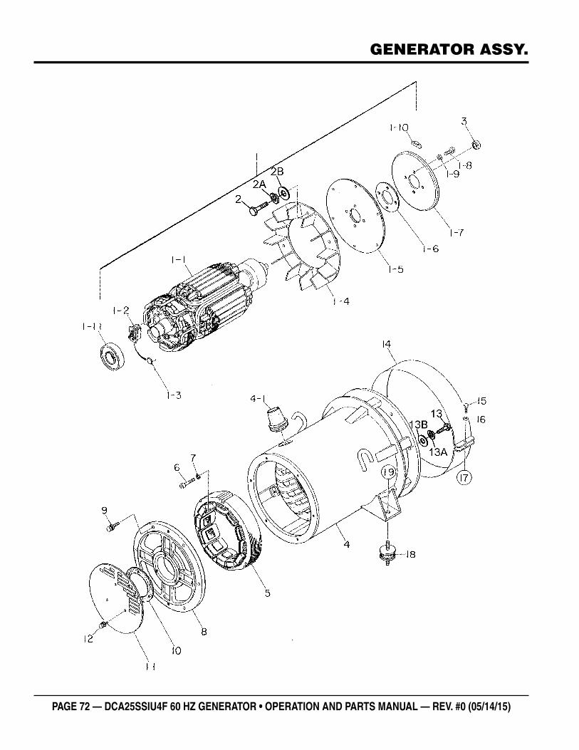
PAGE 72 — DCA25SSIU4F 60 HZ GENERATOR • OPERATION AND PARTS MANUAL — REV. #0 (05/14/15)
GENERATOR ASSY.
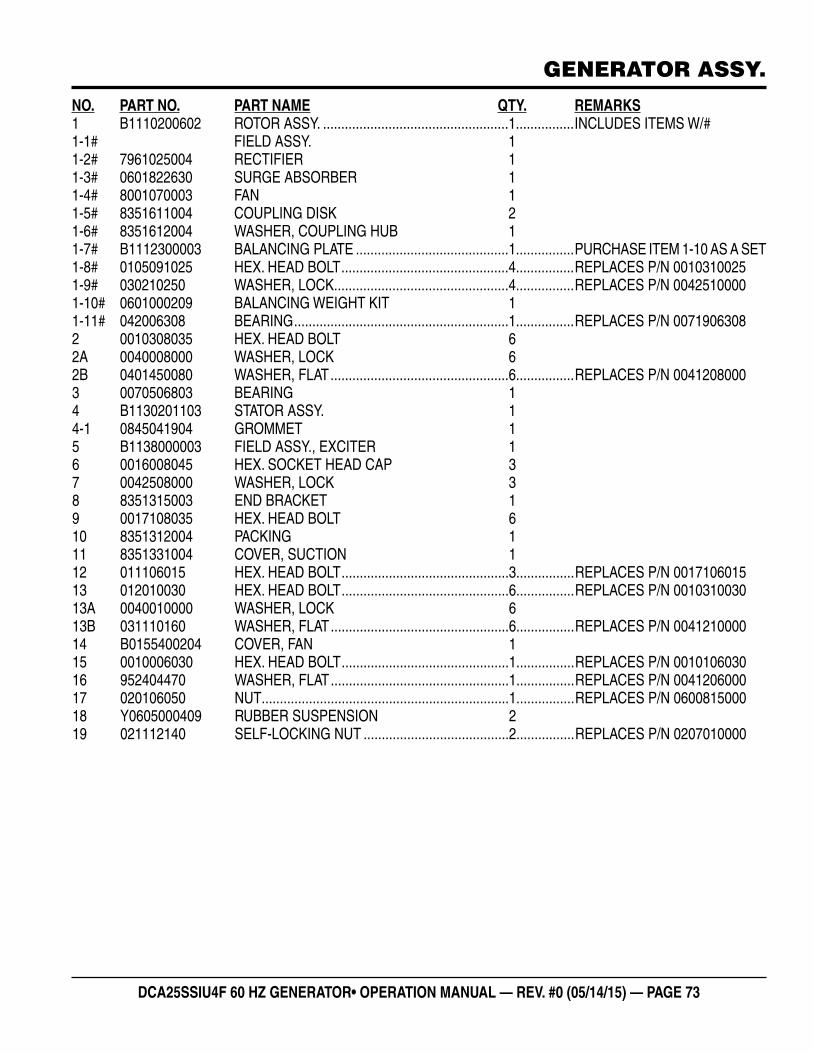
DCA25SSIU4F 60 HZ GENERATOR• OPERATION MANUAL — REV. #0 (05/14/15) — PAGE 73
GENERATOR ASSY.
NO. PART NO. PART NAME QTY. REMARKS1 B1110200602 ROTOR ASSY. ...................................................1................INCLUDES ITEMS W/#1-1# FIELD ASSY. 11-2# 7961025004 RECTIFIER 11-3# 0601822630 SURGE ABSORBER 11-4# 8001070003 FAN 11-5# 8351611004 COUPLING DISK 21-6# 8351612004 WASHER, COUPLING HUB 11-7# B1112300003 BALANCING PLATE ..........................................1................PURCHASE ITEM 1-10 AS A SET1-8# 0105091025 HEX. HEAD BOLT ..............................................4................REPLACES P/N 00103100251-9# 030210250 WASHER, LOCK................................................4................REPLACES P/N 00425100001-10# 0601000209 BALANCING WEIGHT KIT 11-11# 042006308 BEARING ...........................................................1................REPLACES P/N 00719063082 0010308035 HEX. HEAD BOLT 62A 0040008000 WASHER, LOCK 62B 0401450080 WASHER, FLAT .................................................6................REPLACES P/N 00412080003 0070506803 BEARING 14 B1130201103 STATOR ASSY. 14-1 0845041904 GROMMET 15 B1138000003 FIELD ASSY., EXCITER 16 0016008045 HEX. SOCKET HEAD CAP 37 0042508000 WASHER, LOCK 38 8351315003 END BRACKET 19 0017108035 HEX. HEAD BOLT 610 8351312004 PACKING 111 8351331004 COVER, SUCTION 112 011106015 HEX. HEAD BOLT ..............................................3................REPLACES P/N 001710601513 012010030 HEX. HEAD BOLT ..............................................6................REPLACES P/N 001031003013A 0040010000 WASHER, LOCK 613B 031110160 WASHER, FLAT .................................................6................REPLACES P/N 004121000014 B0155400204 COVER, FAN 115 0010006030 HEX. HEAD BOLT ..............................................1................REPLACES P/N 001010603016 952404470 WASHER, FLAT .................................................1................REPLACES P/N 004120600017 020106050 NUT ....................................................................1................REPLACES P/N 060081500018 Y0605000409 RUBBER SUSPENSION 219 021112140 SELF-LOCKING NUT ........................................2................REPLACES P/N 0207010000
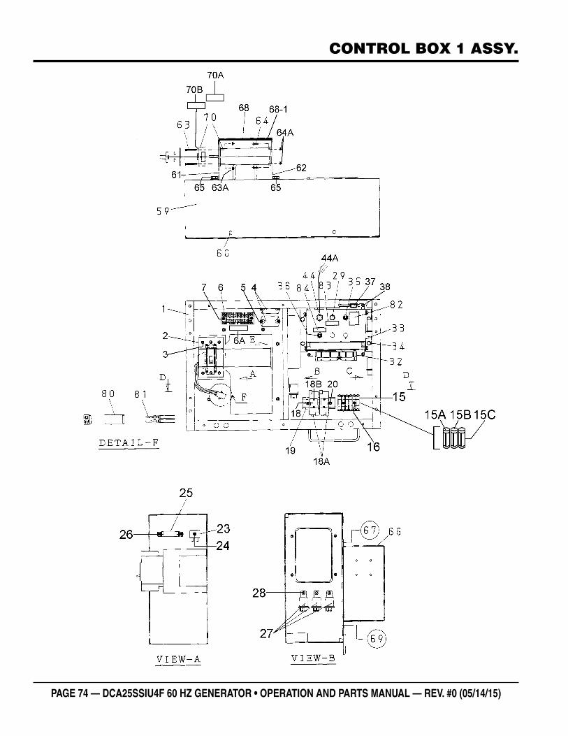
PAGE 74 — DCA25SSIU4F 60 HZ GENERATOR • OPERATION AND PARTS MANUAL — REV. #0 (05/14/15)
CONTROL BOX 1 ASSY.
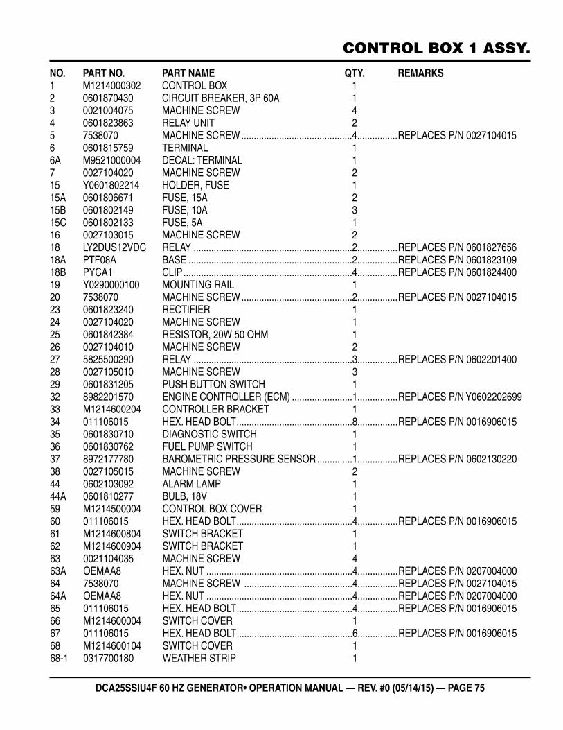
DCA25SSIU4F 60 HZ GENERATOR• OPERATION MANUAL — REV. #0 (05/14/15) — PAGE 75
CONTROL BOX 1 ASSY.
NO. PART NO. PART NAME QTY. REMARKS1 M1214000302 CONTROL BOX 12 0601870430 CIRCUIT BREAKER, 3P 60A 13 0021004075 MACHINE SCREW 44 0601823863 RELAY UNIT 25 7538070 MACHINE SCREW ............................................4................REPLACES P/N 00271040156 0601815759 TERMINAL 16A M9521000004 DECAL: TERMINAL 17 0027104020 MACHINE SCREW 215 Y0601802214 HOLDER, FUSE 115A 0601806671 FUSE, 15A 215B 0601802149 FUSE, 10A 315C 0601802133 FUSE, 5A 116 0027103015 MACHINE SCREW 218 LY2DUS12VDC RELAY ...............................................................2................REPLACES P/N 060182765618A PTF08A BASE .................................................................2................REPLACES P/N 060182310918B PYCA1 CLIP ...................................................................4................REPLACES P/N 060182440019 Y0290000100 MOUNTING RAIL 120 7538070 MACHINE SCREW ............................................2................REPLACES P/N 002710401523 0601823240 RECTIFIER 124 0027104020 MACHINE SCREW 125 0601842384 RESISTOR, 20W 50 OHM 126 0027104010 MACHINE SCREW 227 5825500290 RELAY ...............................................................3................REPLACES P/N 060220140028 0027105010 MACHINE SCREW 329 0601831205 PUSH BUTTON SWITCH 132 8982201570 ENGINE CONTROLLER (ECM) ........................1................REPLACES P/N Y060220269933 M1214600204 CONTROLLER BRACKET 134 011106015 HEX. HEAD BOLT ..............................................8................REPLACES P/N 001690601535 0601830710 DIAGNOSTIC SWITCH 136 0601830762 FUEL PUMP SWITCH 137 8972177780 BAROMETRIC PRESSURE SENSOR ..............1................REPLACES P/N 060213022038 0027105015 MACHINE SCREW 244 0602103092 ALARM LAMP 144A 0601810277 BULB, 18V 159 M1214500004 CONTROL BOX COVER 160 011106015 HEX. HEAD BOLT ..............................................4................REPLACES P/N 001690601561 M1214600804 SWITCH BRACKET 162 M1214600904 SWITCH BRACKET 163 0021104035 MACHINE SCREW 463A OEMAA8 HEX. NUT ..........................................................4................REPLACES P/N 020700400064 7538070 MACHINE SCREW ...........................................4................REPLACES P/N 002710401564A OEMAA8 HEX. NUT ..........................................................4................REPLACES P/N 020700400065 011106015 HEX. HEAD BOLT ..............................................4................REPLACES P/N 001690601566 M1214600004 SWITCH COVER 167 011106015 HEX. HEAD BOLT ..............................................6................REPLACES P/N 001690601568 M1214600104 SWITCH COVER 168-1 0317700180 WEATHER STRIP 1
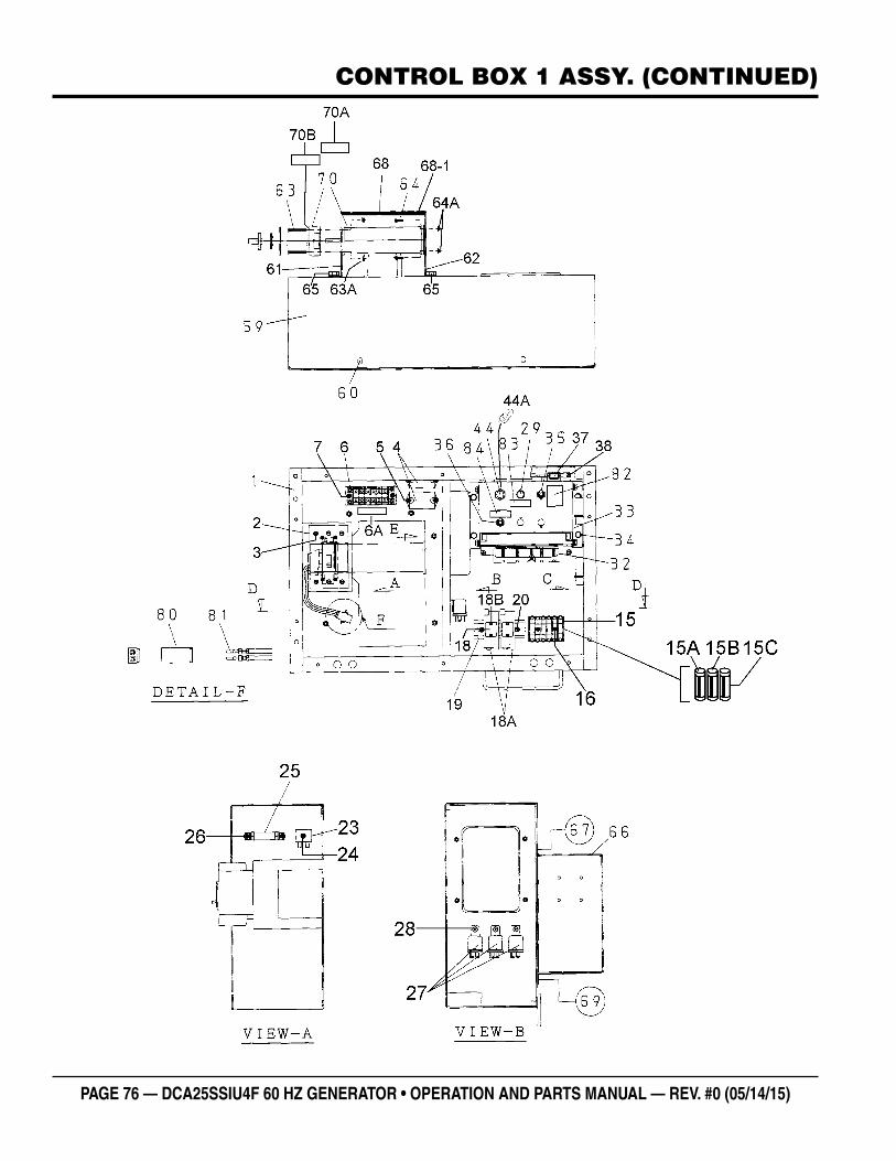
PAGE 76 — DCA25SSIU4F 60 HZ GENERATOR • OPERATION AND PARTS MANUAL — REV. #0 (05/14/15)
CONTROL BOX 1 ASSY. (CONTINUED)
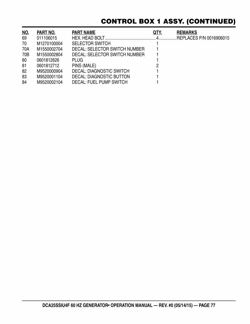
DCA25SSIU4F 60 HZ GENERATOR• OPERATION MANUAL — REV. #0 (05/14/15) — PAGE 77
CONTROL BOX 1 ASSY. (CONTINUED)
NO. PART NO. PART NAME QTY. REMARKS69 011106015 HEX. HEAD BOLT ..............................................4................REPLACES P/N 001690601570 M1270100004 SELECTOR SWITCH 170A M1550002704 DECAL: SELECTOR SWITCH NUMBER 170B M1550002804 DECAL: SELECTOR SWITCH NUMBER 180 0601812626 PLUG 181 0601812712 PINS (MALE) 282 M9520000904 DECAL: DIAGNOSTIC SWITCH 183 M9520001104 DECAL: DIAGNOSTIC BUTTON 184 M9520002104 DECAL: FUEL PUMP SWITCH 1
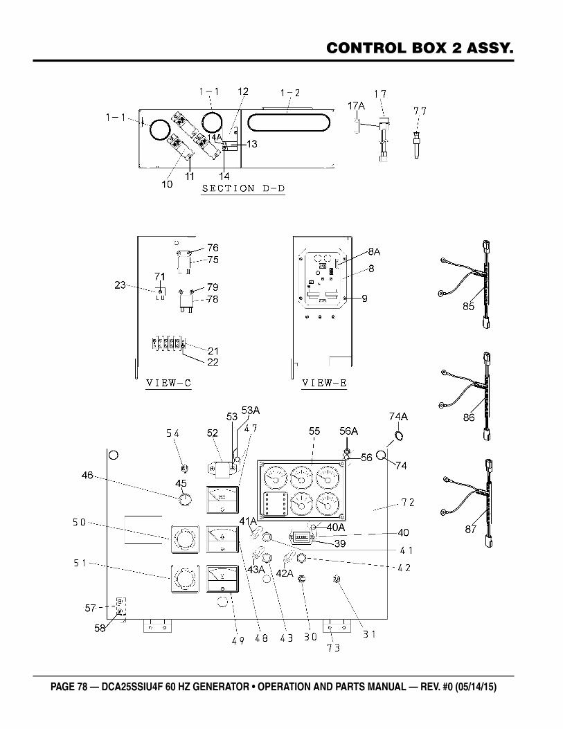
PAGE 78 — DCA25SSIU4F 60 HZ GENERATOR • OPERATION AND PARTS MANUAL — REV. #0 (05/14/15)
CONTROL BOX 2 ASSY.
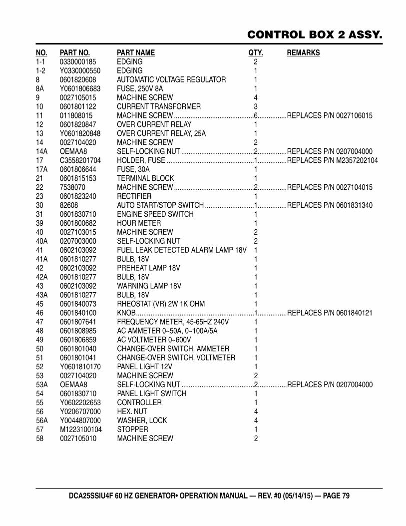
DCA25SSIU4F 60 HZ GENERATOR• OPERATION MANUAL — REV. #0 (05/14/15) — PAGE 79
CONTROL BOX 2 ASSY.
NO. PART NO. PART NAME QTY. REMARKS1-1 0330000185 EDGING 21-2 Y0330000550 EDGING 18 0601820608 AUTOMATIC VOLTAGE REGULATOR 18A Y0601806683 FUSE, 250V 8A 19 0027105015 MACHINE SCREW 410 0601801122 CURRENT TRANSFORMER 311 011808015 MACHINE SCREW ............................................6................REPLACES P/N 002710601512 0601820847 OVER CURRENT RELAY 113 Y0601820848 OVER CURRENT RELAY, 25A 114 0027104020 MACHINE SCREW 214A OEMAA8 SELF-LOCKING NUT ........................................2................REPLACES P/N 020700400017 C3558201704 HOLDER, FUSE ................................................1................REPLACES P/N M235720210417A 0601806644 FUSE, 30A 121 0601815153 TERMINAL BLOCK 122 7538070 MACHINE SCREW ............................................2................REPLACES P/N 002710401523 0601823240 RECTIFIER 130 82608 AUTO START/STOP SWITCH ...........................1................REPLACES P/N 060183134031 0601830710 ENGINE SPEED SWITCH 139 0601800682 HOUR METER 140 0027103015 MACHINE SCREW 240A 0207003000 SELF-LOCKING NUT 241 0602103092 FUEL LEAK DETECTED ALARM LAMP 18V 141A 0601810277 BULB, 18V 142 0602103092 PREHEAT LAMP 18V 142A 0601810277 BULB, 18V 143 0602103092 WARNING LAMP 18V 143A 0601810277 BULB, 18V 145 0601840073 RHEOSTAT (VR) 2W 1K OHM 146 0601840100 KNOB .................................................................1................REPLACES P/N 060184012147 0601807641 FREQUENCY METER, 45-65HZ 240V 148 0601808985 AC AMMETER 0~50A, 0~100A/5A 149 0601806859 AC VOLTMETER 0~600V 150 0601801040 CHANGE-OVER SWITCH, AMMETER 151 0601801041 CHANGE-OVER SWITCH, VOLTMETER 152 Y0601810170 PANEL LIGHT 12V 153 0027104020 MACHINE SCREW 253A OEMAA8 SELF-LOCKING NUT ........................................2................REPLACES P/N 020700400054 0601830710 PANEL LIGHT SWITCH 155 Y0602202653 CONTROLLER 156 Y0206707000 HEX. NUT 456A Y0044807000 WASHER, LOCK 457 M1223100104 STOPPER 158 0027105010 MACHINE SCREW 2
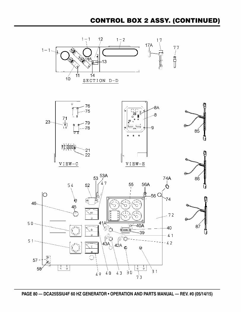
PAGE 80 — DCA25SSIU4F 60 HZ GENERATOR • OPERATION AND PARTS MANUAL — REV. #0 (05/14/15)
CONTROL BOX 2 ASSY. (CONTINUED)
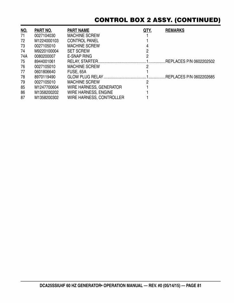
DCA25SSIU4F 60 HZ GENERATOR• OPERATION MANUAL — REV. #0 (05/14/15) — PAGE 81
NO. PART NO. PART NAME QTY. REMARKS71 0027104030 MACHINE SCREW 172 M1224000103 CONTROL PANEL 173 0027105010 MACHINE SCREW 474 M9220100004 SET SCREW 274A 0080200007 E-SNAP RING 275 8944001061 RELAY, STARTER ..............................................1................REPLACES P/N 060220250276 0027105010 MACHINE SCREW 277 0601806640 FUSE, 65A 178 8970119490 GLOW PLUG RELAY .........................................1................REPLACES P/N 060220268579 0027105010 MACHINE SCREW 285 M1247700604 WIRE HARNESS, GENERATOR 186 M1358200202 WIRE HARNESS, ENGINE 187 M1358200302 WIRE HARNESS, CONTROLLER 1
CONTROL BOX 2 ASSY. (CONTINUED)
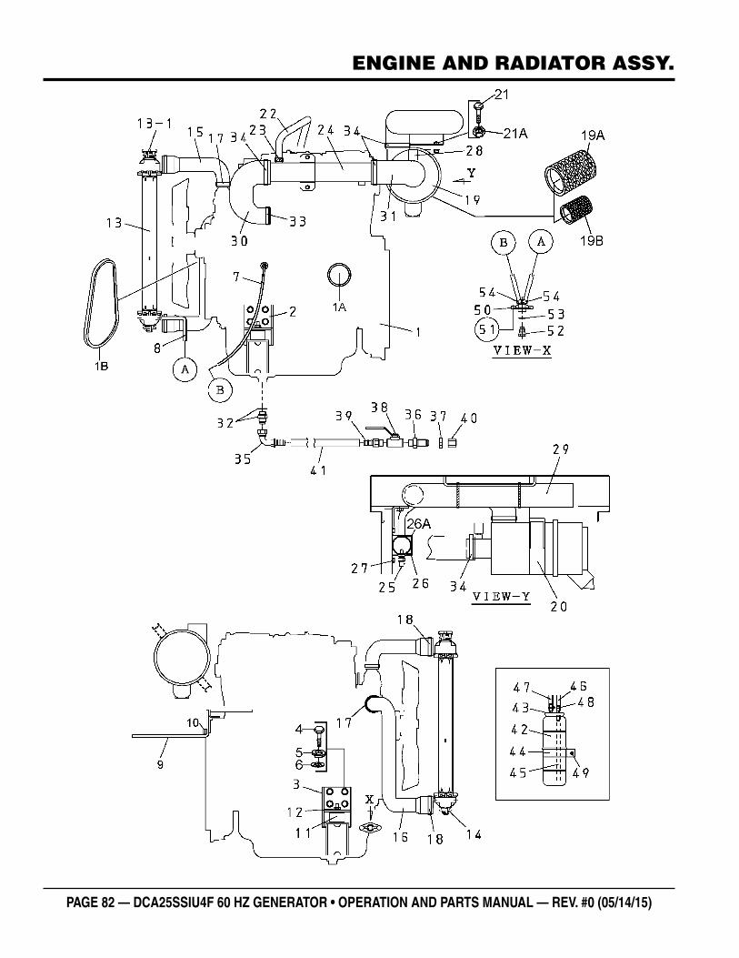
PAGE 82 — DCA25SSIU4F 60 HZ GENERATOR • OPERATION AND PARTS MANUAL — REV. #0 (05/14/15)
ENGINE AND RADIATOR ASSY.
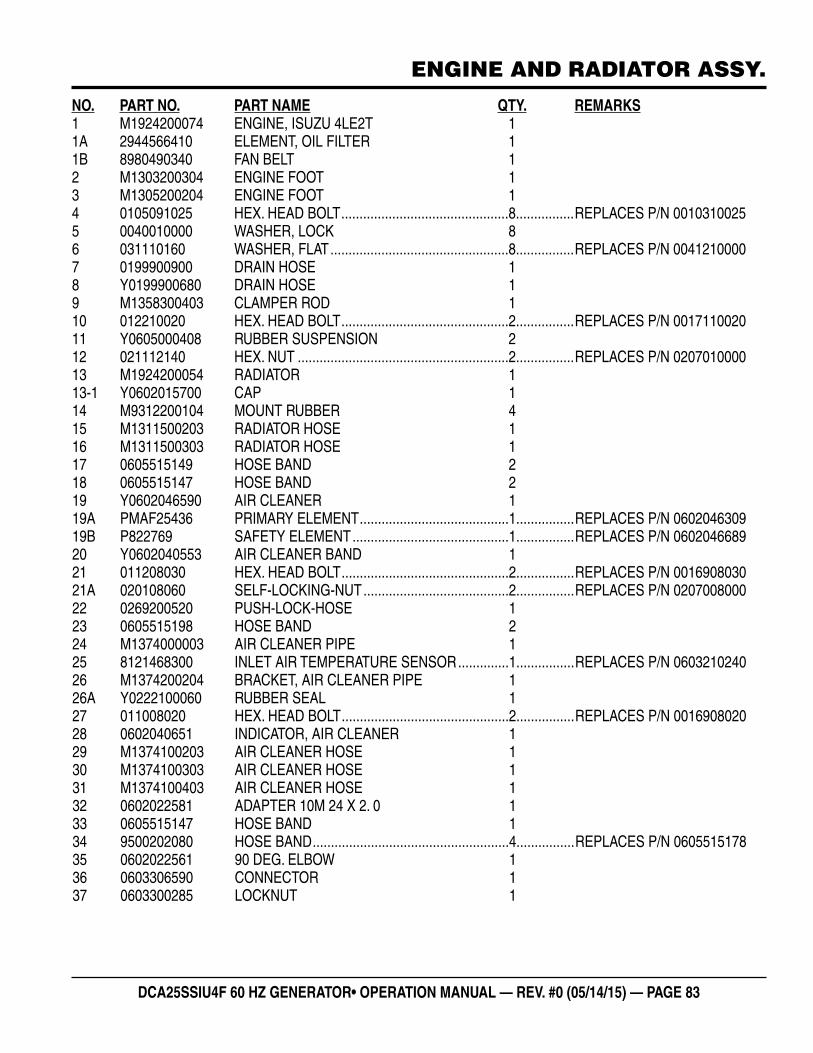
DCA25SSIU4F 60 HZ GENERATOR• OPERATION MANUAL — REV. #0 (05/14/15) — PAGE 83
ENGINE AND RADIATOR ASSY.
NO. PART NO. PART NAME QTY. REMARKS1 M1924200074 ENGINE, ISUZU 4LE2T 11A 2944566410 ELEMENT, OIL FILTER 11B 8980490340 FAN BELT 12 M1303200304 ENGINE FOOT 13 M1305200204 ENGINE FOOT 14 0105091025 HEX. HEAD BOLT ..............................................8................REPLACES P/N 00103100255 0040010000 WASHER, LOCK 86 031110160 WASHER, FLAT .................................................8................REPLACES P/N 00412100007 0199900900 DRAIN HOSE 18 Y0199900680 DRAIN HOSE 19 M1358300403 CLAMPER ROD 110 012210020 HEX. HEAD BOLT ..............................................2................REPLACES P/N 001711002011 Y0605000408 RUBBER SUSPENSION 212 021112140 HEX. NUT ..........................................................2................REPLACES P/N 020701000013 M1924200054 RADIATOR 113-1 Y0602015700 CAP 114 M9312200104 MOUNT RUBBER 415 M1311500203 RADIATOR HOSE 116 M1311500303 RADIATOR HOSE 117 0605515149 HOSE BAND 218 0605515147 HOSE BAND 219 Y0602046590 AIR CLEANER 119A PMAF25436 PRIMARY ELEMENT .........................................1................REPLACES P/N 060204630919B P822769 SAFETY ELEMENT ...........................................1................REPLACES P/N 060204668920 Y0602040553 AIR CLEANER BAND 121 011208030 HEX. HEAD BOLT ..............................................2................REPLACES P/N 001690803021A 020108060 SELF-LOCKING-NUT ........................................2................REPLACES P/N 020700800022 0269200520 PUSH-LOCK-HOSE 123 0605515198 HOSE BAND 224 M1374000003 AIR CLEANER PIPE 125 8121468300 INLET AIR TEMPERATURE SENSOR ..............1................REPLACES P/N 060321024026 M1374200204 BRACKET, AIR CLEANER PIPE 126A Y0222100060 RUBBER SEAL 127 011008020 HEX. HEAD BOLT ..............................................2................REPLACES P/N 001690802028 0602040651 INDICATOR, AIR CLEANER 129 M1374100203 AIR CLEANER HOSE 130 M1374100303 AIR CLEANER HOSE 131 M1374100403 AIR CLEANER HOSE 132 0602022581 ADAPTER 10M 24 X 2. 0 133 0605515147 HOSE BAND 134 9500202080 HOSE BAND ......................................................4................REPLACES P/N 060551517835 0602022561 90 DEG. ELBOW 136 0603306590 CONNECTOR 137 0603300285 LOCKNUT 1
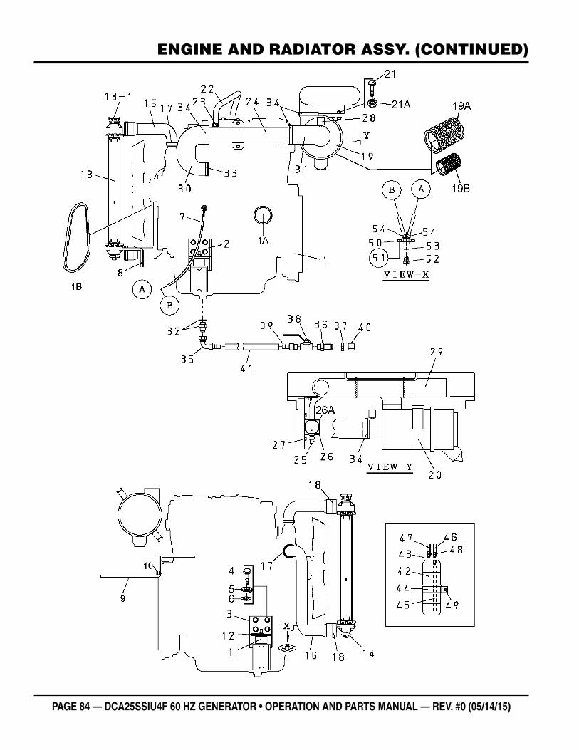
PAGE 84 — DCA25SSIU4F 60 HZ GENERATOR • OPERATION AND PARTS MANUAL — REV. #0 (05/14/15)
ENGINE AND RADIATOR ASSY. (CONTINUED)
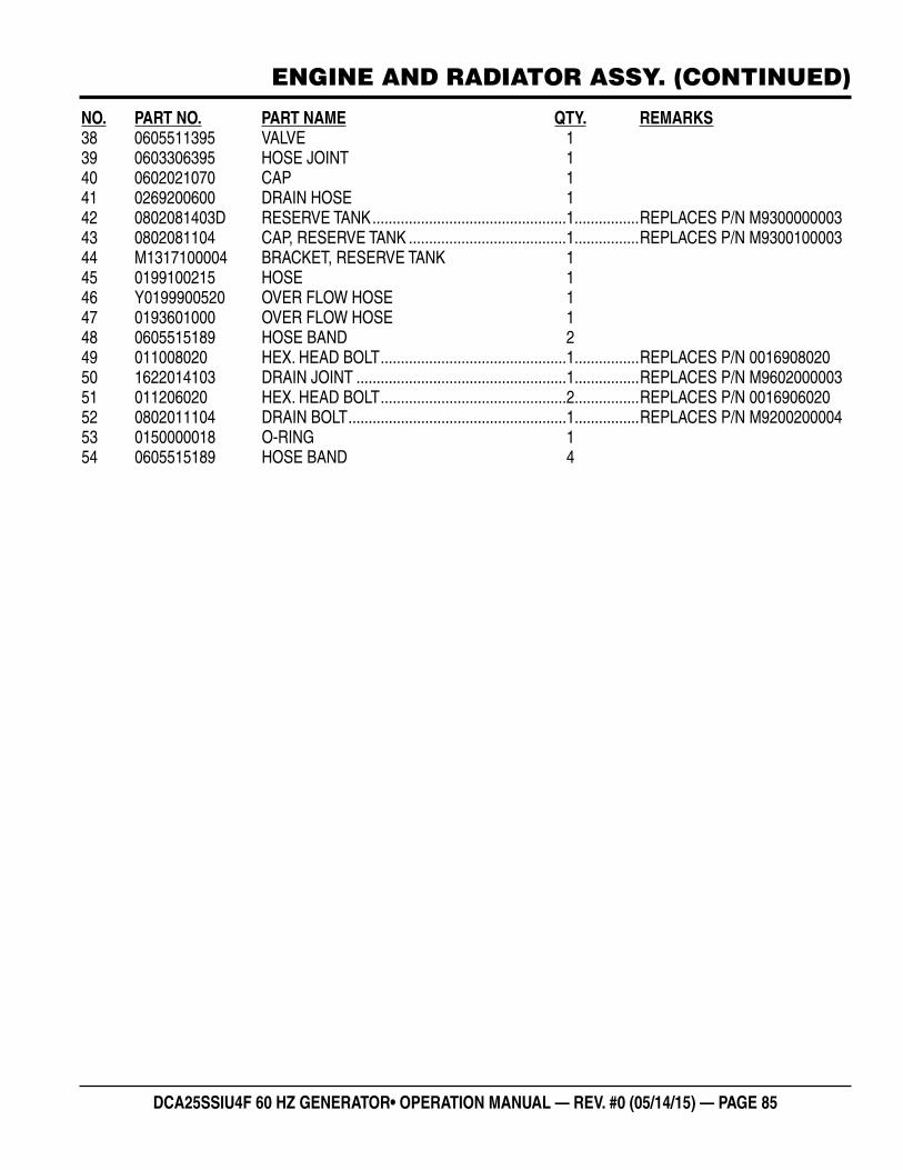
DCA25SSIU4F 60 HZ GENERATOR• OPERATION MANUAL — REV. #0 (05/14/15) — PAGE 85
ENGINE AND RADIATOR ASSY. (CONTINUED)
NO. PART NO. PART NAME QTY. REMARKS38 0605511395 VALVE 139 0603306395 HOSE JOINT 140 0602021070 CAP 141 0269200600 DRAIN HOSE 142 0802081403D RESERVE TANK ................................................1................REPLACES P/N M930000000343 0802081104 CAP, RESERVE TANK .......................................1................REPLACES P/N M930010000344 M1317100004 BRACKET, RESERVE TANK 145 0199100215 HOSE 146 Y0199900520 OVER FLOW HOSE 147 0193601000 OVER FLOW HOSE 148 0605515189 HOSE BAND 249 011008020 HEX. HEAD BOLT ..............................................1................REPLACES P/N 001690802050 1622014103 DRAIN JOINT ....................................................1................REPLACES P/N M960200000351 011206020 HEX. HEAD BOLT ..............................................2................REPLACES P/N 001690602052 0802011104 DRAIN BOLT ......................................................1................REPLACES P/N M920020000453 0150000018 O-RING 154 0605515189 HOSE BAND 4
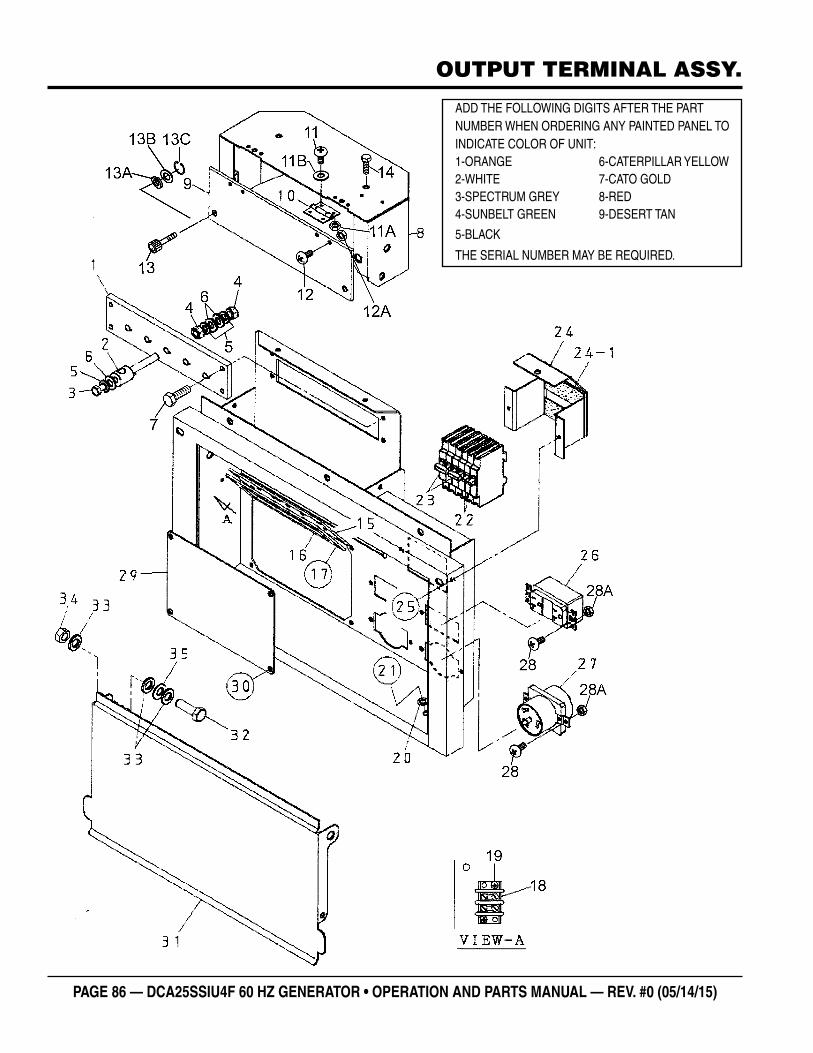
PAGE 86 — DCA25SSIU4F 60 HZ GENERATOR • OPERATION AND PARTS MANUAL — REV. #0 (05/14/15)
OUTPUT TERMINAL ASSY.
ADD THE FOLLOWING DIGITS AFTER THE PART NUMBER WHEN ORDERING ANY PAINTED PANEL TO INDICATE COLOR OF UNIT:1-ORANGE 6-CATERPILLAR YELLOW2-WHITE 7-CATO GOLD3-SPECTRUM GREY 8-RED4-SUNBELT GREEN 9-DESERT TAN
5-BLACK
THE SERIAL NUMBER MAY BE REQUIRED.
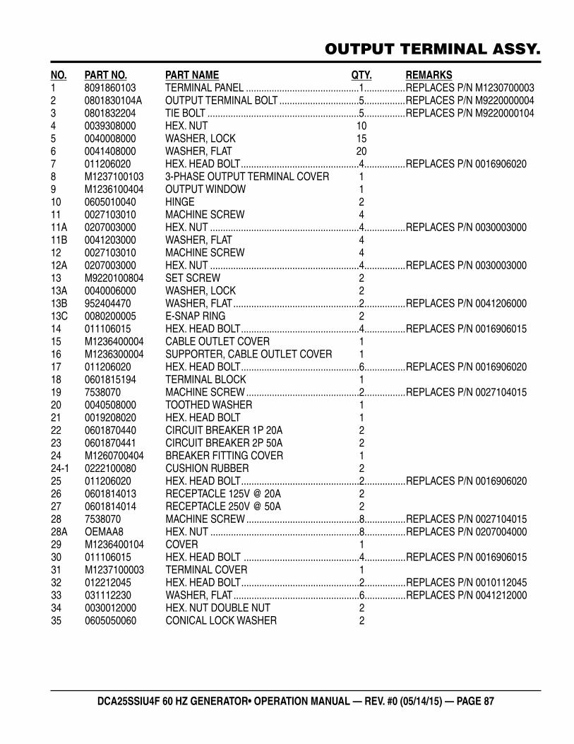
DCA25SSIU4F 60 HZ GENERATOR• OPERATION MANUAL — REV. #0 (05/14/15) — PAGE 87
OUTPUT TERMINAL ASSY.
NO. PART NO. PART NAME QTY. REMARKS1 8091860103 TERMINAL PANEL ............................................1................REPLACES P/N M12307000032 0801830104A OUTPUT TERMINAL BOLT ...............................5................REPLACES P/N M92200000043 0801832204 TIE BOLT ...........................................................5................REPLACES P/N M92200001044 0039308000 HEX. NUT 105 0040008000 WASHER, LOCK 156 0041408000 WASHER, FLAT 207 011206020 HEX. HEAD BOLT ..............................................4................REPLACES P/N 00169060208 M1237100103 3-PHASE OUTPUT TERMINAL COVER 19 M1236100404 OUTPUT WINDOW 110 0605010040 HINGE 211 0027103010 MACHINE SCREW 411A 0207003000 HEX. NUT ..........................................................4................REPLACES P/N 003000300011B 0041203000 WASHER, FLAT 412 0027103010 MACHINE SCREW 412A 0207003000 HEX. NUT ..........................................................4................REPLACES P/N 003000300013 M9220100804 SET SCREW 213A 0040006000 WASHER, LOCK 213B 952404470 WASHER, FLAT .................................................2................REPLACES P/N 004120600013C 0080200005 E-SNAP RING 214 011106015 HEX. HEAD BOLT ..............................................4................REPLACES P/N 001690601515 M1236400004 CABLE OUTLET COVER 116 M1236300004 SUPPORTER, CABLE OUTLET COVER 117 011206020 HEX. HEAD BOLT ..............................................6................REPLACES P/N 001690602018 0601815194 TERMINAL BLOCK 119 7538070 MACHINE SCREW ............................................2................REPLACES P/N 002710401520 0040508000 TOOTHED WASHER 121 0019208020 HEX. HEAD BOLT 122 0601870440 CIRCUIT BREAKER 1P 20A 223 0601870441 CIRCUIT BREAKER 2P 50A 224 M1260700404 BREAKER FITTING COVER 124-1 0222100080 CUSHION RUBBER 225 011206020 HEX. HEAD BOLT ..............................................2................REPLACES P/N 001690602026 0601814013 RECEPTACLE 125V @ 20A 227 0601814014 RECEPTACLE 250V @ 50A 228 7538070 MACHINE SCREW ............................................8................REPLACES P/N 002710401528A OEMAA8 HEX. NUT ..........................................................8................REPLACES P/N 020700400029 M1236400104 COVER 130 011106015 HEX. HEAD BOLT .............................................4................REPLACES P/N 001690601531 M1237100003 TERMINAL COVER 132 012212045 HEX. HEAD BOLT ..............................................2................REPLACES P/N 001011204533 031112230 WASHER, FLAT .................................................6................REPLACES P/N 004121200034 0030012000 HEX. NUT DOUBLE NUT 235 0605050060 CONICAL LOCK WASHER 2
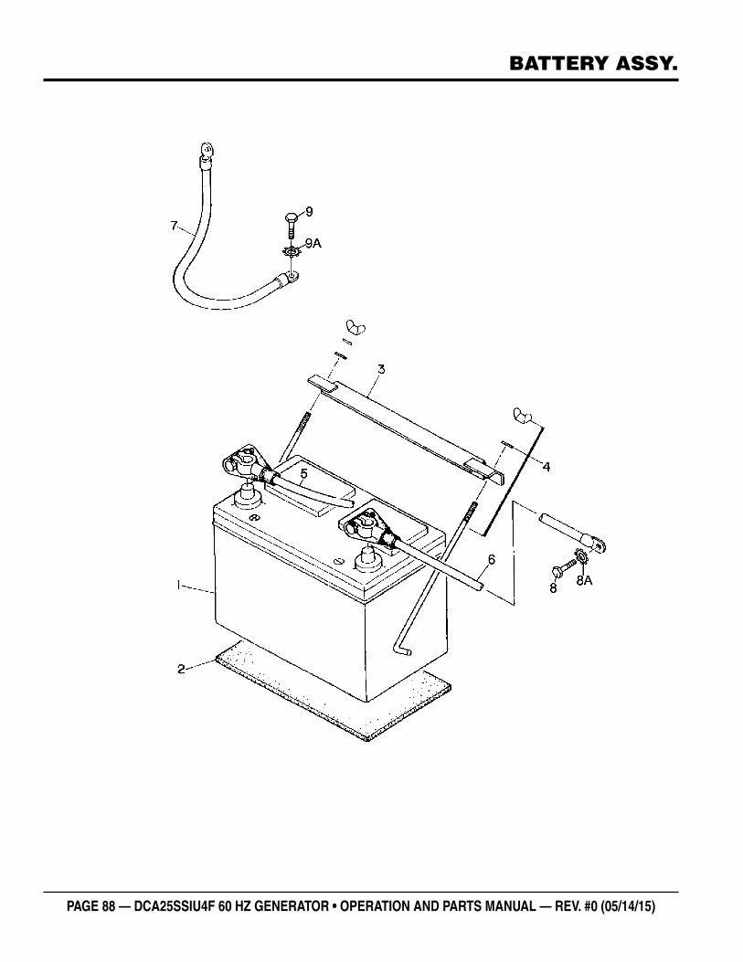
PAGE 88 — DCA25SSIU4F 60 HZ GENERATOR • OPERATION AND PARTS MANUAL — REV. #0 (05/14/15)
BATTERY ASSY.
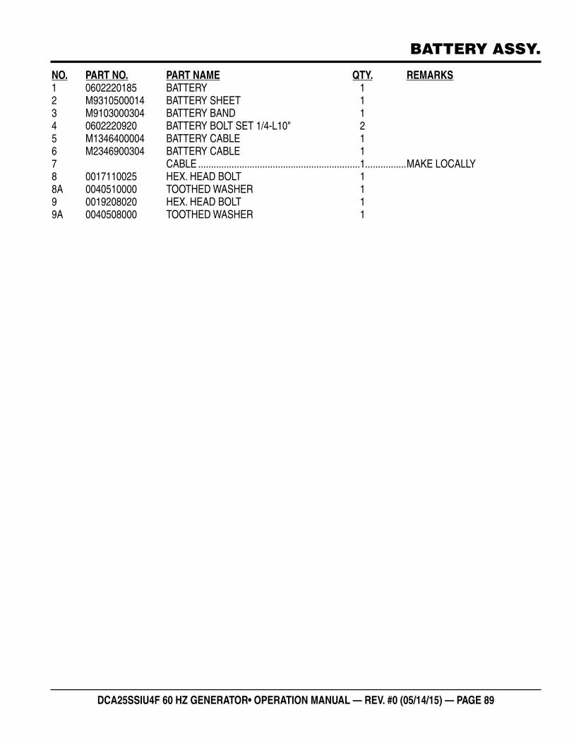
DCA25SSIU4F 60 HZ GENERATOR• OPERATION MANUAL — REV. #0 (05/14/15) — PAGE 89
BATTERY ASSY.
NO. PART NO. PART NAME QTY. REMARKS1 0602220185 BATTERY 12 M9310500014 BATTERY SHEET 13 M9103000304 BATTERY BAND 14 0602220920 BATTERY BOLT SET 1/4-L10" 25 M1346400004 BATTERY CABLE 16 M2346900304 BATTERY CABLE 17 CABLE ...............................................................1................MAKE LOCALLY8 0017110025 HEX. HEAD BOLT 18A 0040510000 TOOTHED WASHER 19 0019208020 HEX. HEAD BOLT 19A 0040508000 TOOTHED WASHER 1
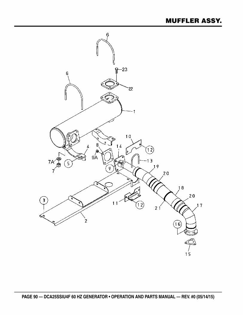
PAGE 90 — DCA25SSIU4F 60 HZ GENERATOR • OPERATION AND PARTS MANUAL — REV. #0 (05/14/15)
MUFFLER ASSY.
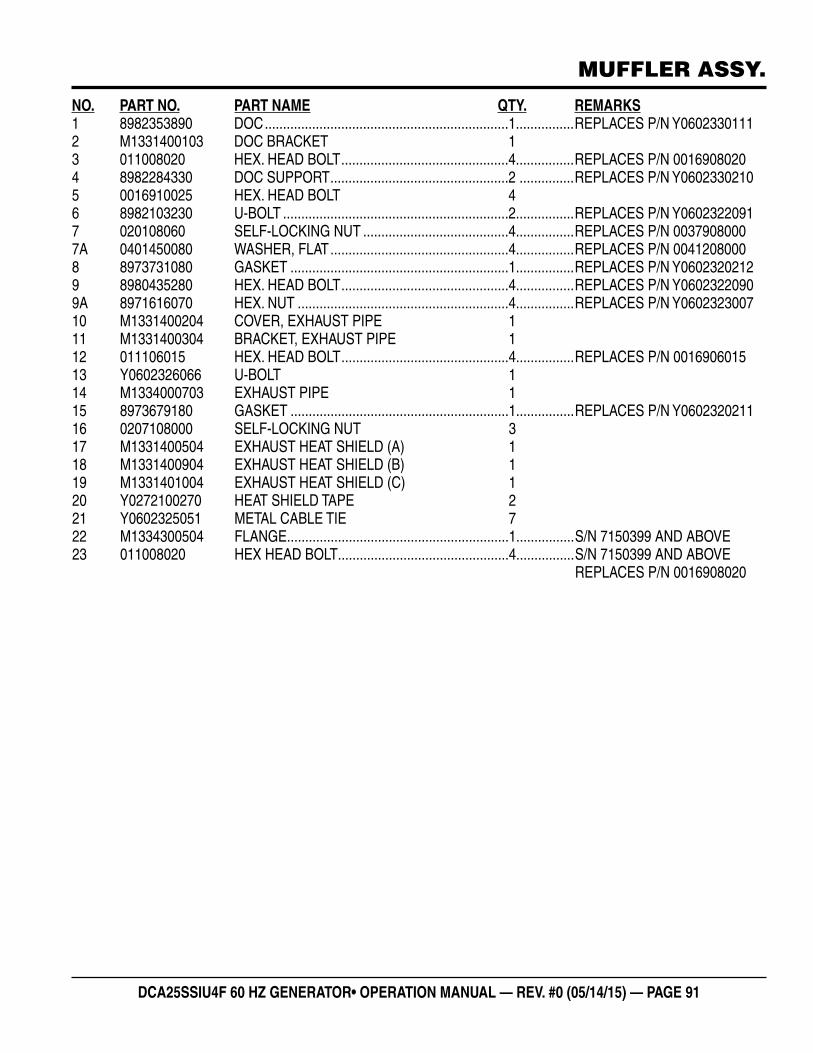
DCA25SSIU4F 60 HZ GENERATOR• OPERATION MANUAL — REV. #0 (05/14/15) — PAGE 91
MUFFLER ASSY.
NO. PART NO. PART NAME QTY. REMARKS1 8982353890 DOC ...................................................................1................REPLACES P/N Y06023301112 M1331400103 DOC BRACKET 13 011008020 HEX. HEAD BOLT ..............................................4................REPLACES P/N 00169080204 8982284330 DOC SUPPORT .................................................2 ...............REPLACES P/N Y06023302105 0016910025 HEX. HEAD BOLT 46 8982103230 U-BOLT ..............................................................2................REPLACES P/N Y06023220917 020108060 SELF-LOCKING NUT ........................................4................REPLACES P/N 00379080007A 0401450080 WASHER, FLAT .................................................4................REPLACES P/N 00412080008 8973731080 GASKET ............................................................1................REPLACES P/N Y06023202129 8980435280 HEX. HEAD BOLT ..............................................4................REPLACES P/N Y06023220909A 8971616070 HEX. NUT ..........................................................4................REPLACES P/N Y060232300710 M1331400204 COVER, EXHAUST PIPE 111 M1331400304 BRACKET, EXHAUST PIPE 112 011106015 HEX. HEAD BOLT ..............................................4................REPLACES P/N 001690601513 Y0602326066 U-BOLT 114 M1334000703 EXHAUST PIPE 115 8973679180 GASKET ............................................................1................REPLACES P/N Y060232021116 0207108000 SELF-LOCKING NUT 317 M1331400504 EXHAUST HEAT SHIELD (A) 118 M1331400904 EXHAUST HEAT SHIELD (B) 119 M1331401004 EXHAUST HEAT SHIELD (C) 120 Y0272100270 HEAT SHIELD TAPE 221 Y0602325051 METAL CABLE TIE 722 M1334300504 FLANGE .............................................................1................S/N 7150399 AND ABOVE23 011008020 HEX HEAD BOLT ...............................................4................S/N 7150399 AND ABOVE REPLACES P/N 0016908020
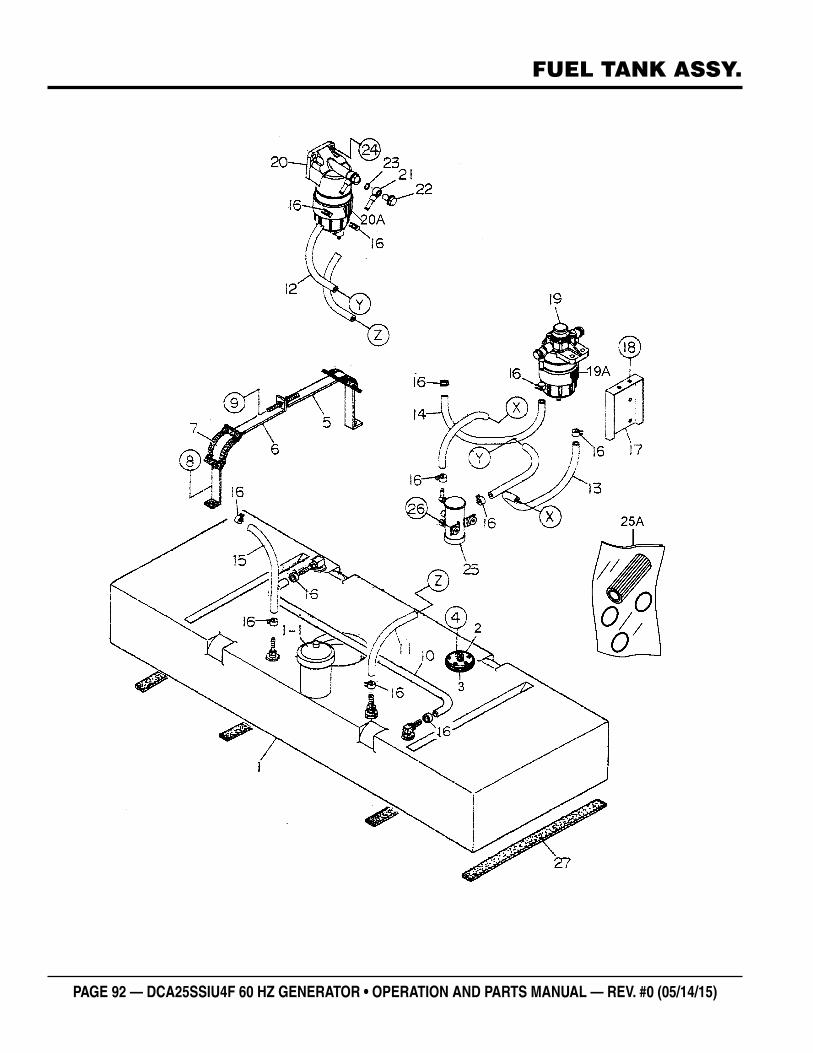
PAGE 92 — DCA25SSIU4F 60 HZ GENERATOR • OPERATION AND PARTS MANUAL — REV. #0 (05/14/15)
FUEL TANK ASSY.
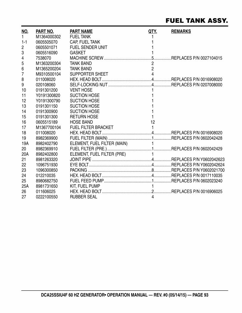
DCA25SSIU4F 60 HZ GENERATOR• OPERATION MANUAL — REV. #0 (05/14/15) — PAGE 93
FUEL TANK ASSY.
NO. PART NO. PART NAME QTY. REMARKS1 M1364000302 FUEL TANK 11-1 0605505070 CAP, FUEL TANK 12 0605501071 FUEL SENDER UNIT 13 0605516090 GASKET 14 7538070 MACHINE SCREW ............................................5................REPLACES P/N 00271040155 M1363200304 TANK BAND 26 M1365200204 TANK BAND 27 M9310500104 SUPPORTER SHEET 48 011008020 HEX. HEAD BOLT ..............................................4................REPLACES P/N 00169080209 020108060 SELF-LOCKING NUT ........................................4................REPLACES P/N 020700800010 0191301200 VENT HOSE 111 Y0191300820 SUCTION HOSE 112 Y0191300790 SUCTION HOSE 113 0191301150 SUCTION HOSE 114 0191300900 SUCTION HOSE 115 0191301300 RETURN HOSE 116 0605515189 HOSE BAND 1217 M1367700104 FUEL FILTER BRACKET 118 011008020 HEX. HEAD BOLT ..............................................4................REPLACES P/N 001690802019 8982369900 FUEL FILTER (MAIN) ........................................1................REPLACES P/N 060204242819A 8982402790 ELEMENT, FUEL FILTER (MAIN) 120 8982369910 FUEL FILTER (PRE.) .........................................1................REPLACES P/N 060204242920A 8982402800 ELEMENT, FUEL FILTER (PRE) 121 8981263320 JOINT PIPE .......................................................4................REPLACES P/N Y060204262322 1096751930 EYE BOLT ..........................................................4................REPLACES P/N Y060204262423 1096300850 PACKING ...........................................................8................REPLACES P/N Y060202170024 012210035 HEX. HEAD BOLT ..............................................4................REPLACES P/N 001711003525 8980682750 FUEL FEED PUMP ............................................1................REPLACES P/N 060202324025A 8981731650 KIT, FUEL PUMP 126 011606025 HEX. HEAD BOLT ..............................................2................REPLACES P/N 001690602527 0222100550 RUBBER SEAL 4
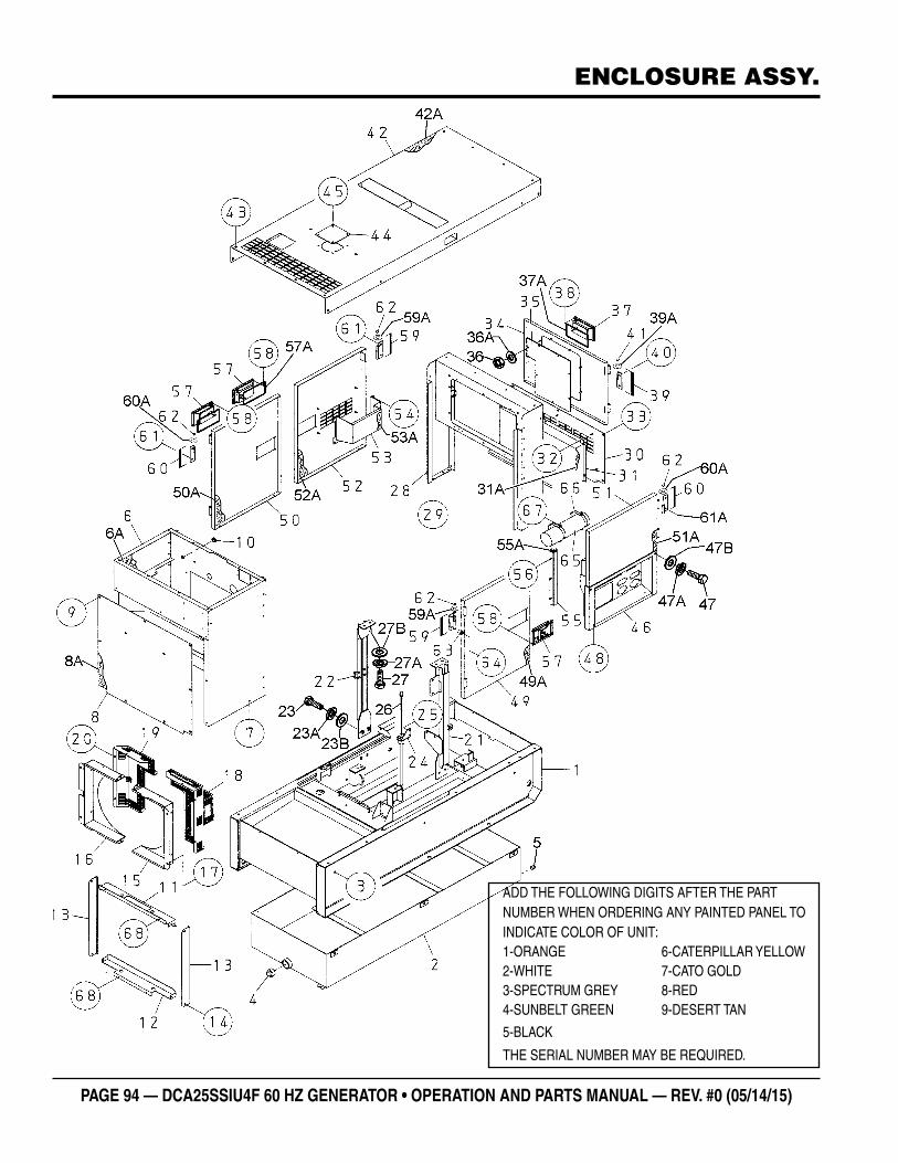
PAGE 94 — DCA25SSIU4F 60 HZ GENERATOR • OPERATION AND PARTS MANUAL — REV. #0 (05/14/15)
ENCLOSURE ASSY.
ADD THE FOLLOWING DIGITS AFTER THE PART NUMBER WHEN ORDERING ANY PAINTED PANEL TO INDICATE COLOR OF UNIT:1-ORANGE 6-CATERPILLAR YELLOW2-WHITE 7-CATO GOLD3-SPECTRUM GREY 8-RED4-SUNBELT GREEN 9-DESERT TAN
5-BLACK
THE SERIAL NUMBER MAY BE REQUIRED.
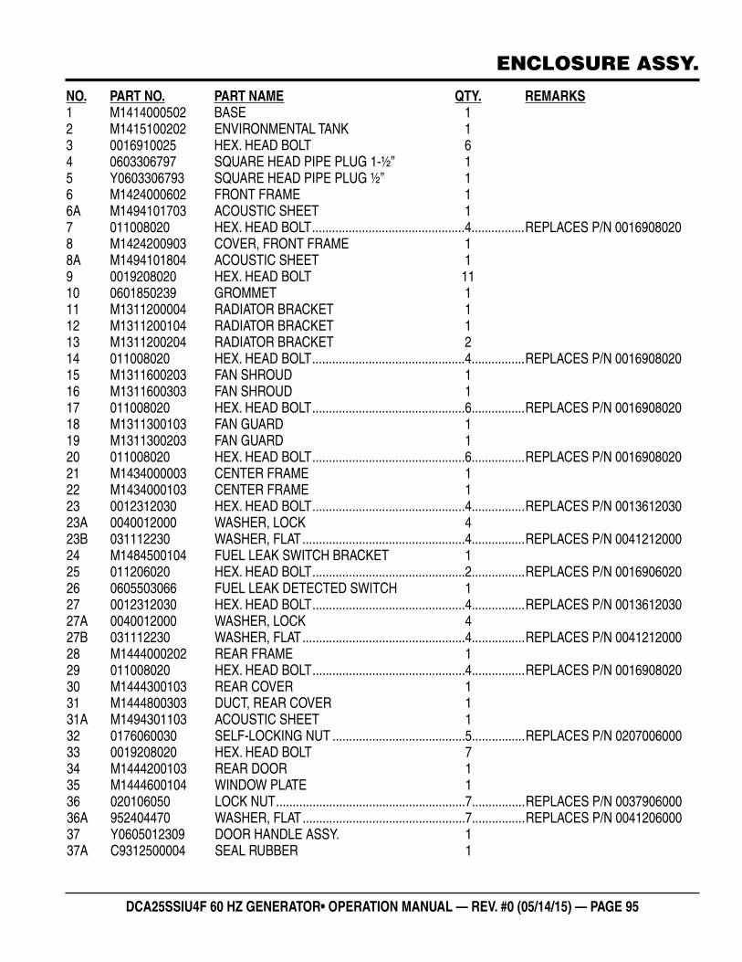
DCA25SSIU4F 60 HZ GENERATOR• OPERATION MANUAL — REV. #0 (05/14/15) — PAGE 95
ENCLOSURE ASSY.
NO. PART NO. PART NAME QTY. REMARKS1 M1414000502 BASE 12 M1415100202 ENVIRONMENTAL TANK 13 0016910025 HEX. HEAD BOLT 64 0603306797 SQUARE HEAD PIPE PLUG 1-½” 15 Y0603306793 SQUARE HEAD PIPE PLUG ½” 16 M1424000602 FRONT FRAME 16A M1494101703 ACOUSTIC SHEET 17 011008020 HEX. HEAD BOLT ..............................................4................REPLACES P/N 00169080208 M1424200903 COVER, FRONT FRAME 18A M1494101804 ACOUSTIC SHEET 19 0019208020 HEX. HEAD BOLT 1110 0601850239 GROMMET 111 M1311200004 RADIATOR BRACKET 112 M1311200104 RADIATOR BRACKET 113 M1311200204 RADIATOR BRACKET 214 011008020 HEX. HEAD BOLT ..............................................4................REPLACES P/N 001690802015 M1311600203 FAN SHROUD 116 M1311600303 FAN SHROUD 117 011008020 HEX. HEAD BOLT ..............................................6................REPLACES P/N 001690802018 M1311300103 FAN GUARD 119 M1311300203 FAN GUARD 120 011008020 HEX. HEAD BOLT ..............................................6................REPLACES P/N 001690802021 M1434000003 CENTER FRAME 122 M1434000103 CENTER FRAME 123 0012312030 HEX. HEAD BOLT ..............................................4................REPLACES P/N 001361203023A 0040012000 WASHER, LOCK 423B 031112230 WASHER, FLAT .................................................4................REPLACES P/N 004121200024 M1484500104 FUEL LEAK SWITCH BRACKET 125 011206020 HEX. HEAD BOLT ..............................................2................REPLACES P/N 001690602026 0605503066 FUEL LEAK DETECTED SWITCH 127 0012312030 HEX. HEAD BOLT ..............................................4................REPLACES P/N 001361203027A 0040012000 WASHER, LOCK 427B 031112230 WASHER, FLAT .................................................4................REPLACES P/N 004121200028 M1444000202 REAR FRAME 129 011008020 HEX. HEAD BOLT ..............................................4................REPLACES P/N 001690802030 M1444300103 REAR COVER 131 M1444800303 DUCT, REAR COVER 131A M1494301103 ACOUSTIC SHEET 132 0176060030 SELF-LOCKING NUT ........................................5................REPLACES P/N 020700600033 0019208020 HEX. HEAD BOLT 734 M1444200103 REAR DOOR 135 M1444600104 WINDOW PLATE 136 020106050 LOCK NUT .........................................................7................REPLACES P/N 003790600036A 952404470 WASHER, FLAT .................................................7................REPLACES P/N 004120600037 Y0605012309 DOOR HANDLE ASSY. 137A C9312500004 SEAL RUBBER 1
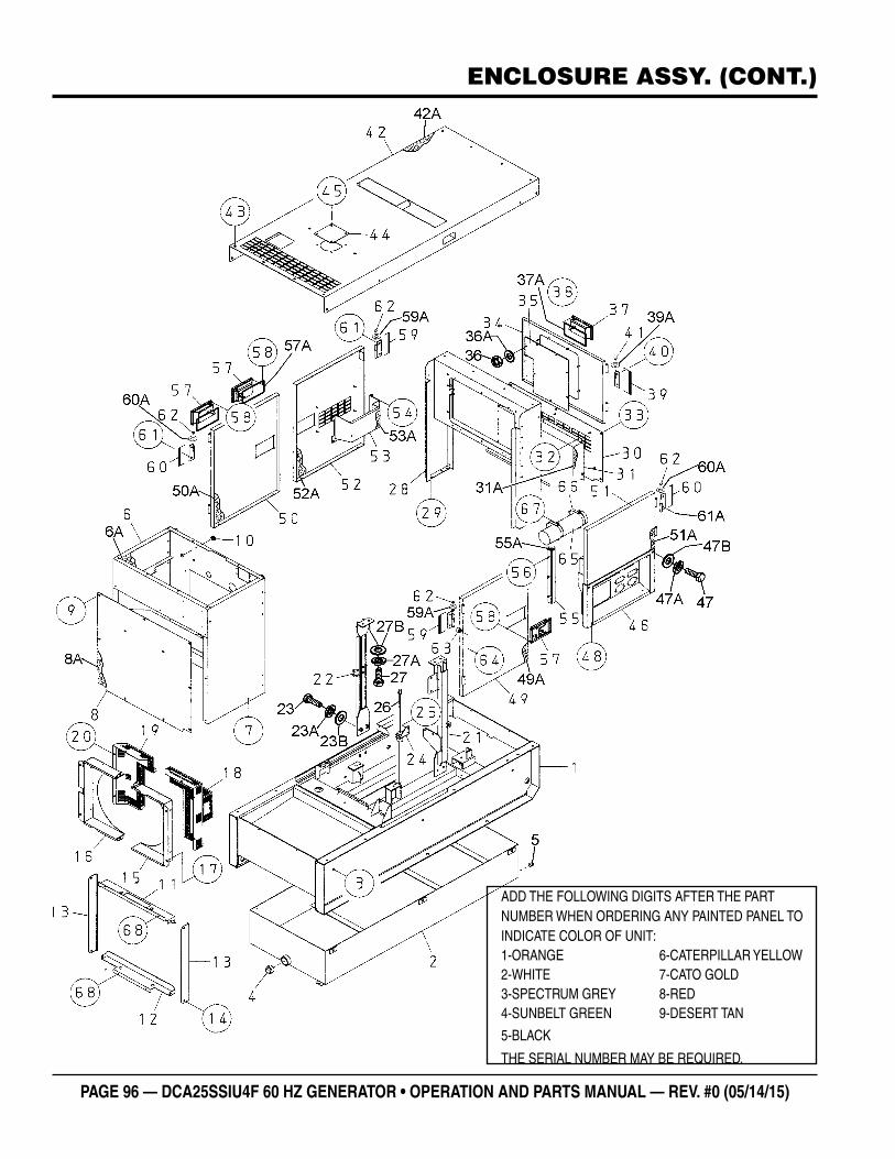
PAGE 96 — DCA25SSIU4F 60 HZ GENERATOR • OPERATION AND PARTS MANUAL — REV. #0 (05/14/15)
ENCLOSURE ASSY. (CONT.)
ADD THE FOLLOWING DIGITS AFTER THE PART NUMBER WHEN ORDERING ANY PAINTED PANEL TO INDICATE COLOR OF UNIT:1-ORANGE 6-CATERPILLAR YELLOW2-WHITE 7-CATO GOLD3-SPECTRUM GREY 8-RED4-SUNBELT GREEN 9-DESERT TAN
5-BLACK
THE SERIAL NUMBER MAY BE REQUIRED.
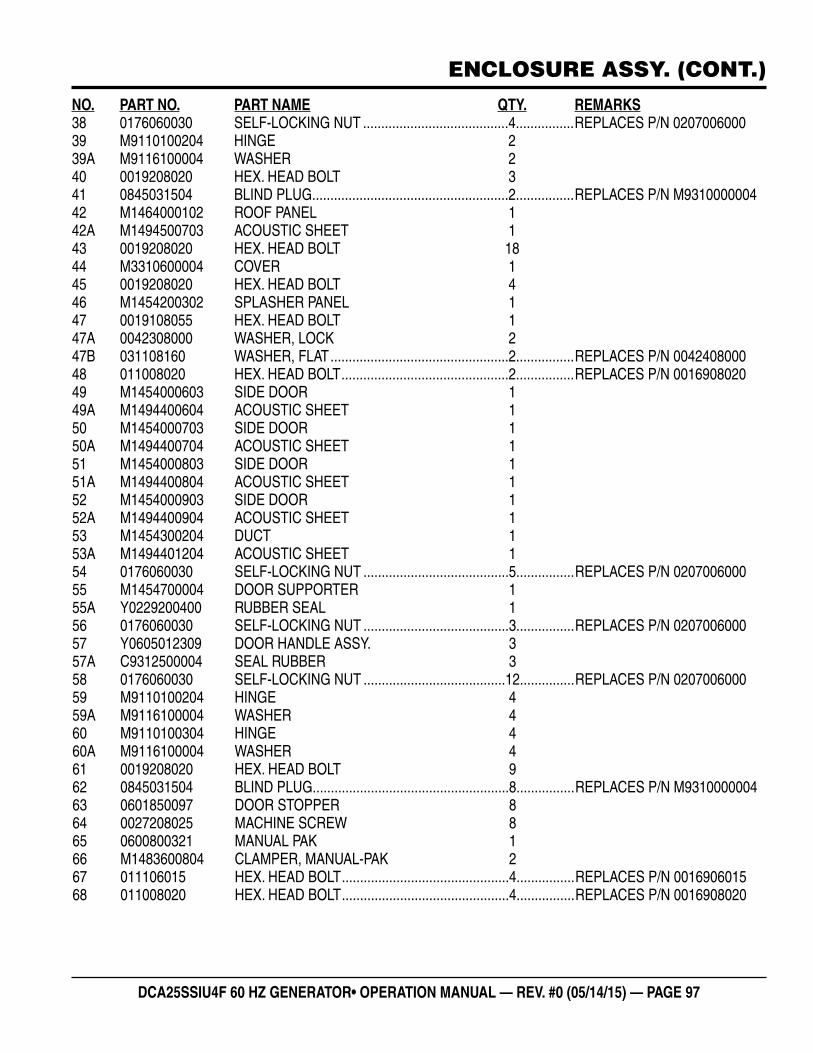
DCA25SSIU4F 60 HZ GENERATOR• OPERATION MANUAL — REV. #0 (05/14/15) — PAGE 97
ENCLOSURE ASSY. (CONT.)
NO. PART NO. PART NAME QTY. REMARKS38 0176060030 SELF-LOCKING NUT ........................................4................REPLACES P/N 020700600039 M9110100204 HINGE 239A M9116100004 WASHER 240 0019208020 HEX. HEAD BOLT 341 0845031504 BLIND PLUG ......................................................2................REPLACES P/N M931000000442 M1464000102 ROOF PANEL 142A M1494500703 ACOUSTIC SHEET 143 0019208020 HEX. HEAD BOLT 1844 M3310600004 COVER 145 0019208020 HEX. HEAD BOLT 446 M1454200302 SPLASHER PANEL 147 0019108055 HEX. HEAD BOLT 147A 0042308000 WASHER, LOCK 247B 031108160 WASHER, FLAT .................................................2................REPLACES P/N 004240800048 011008020 HEX. HEAD BOLT ..............................................2................REPLACES P/N 001690802049 M1454000603 SIDE DOOR 149A M1494400604 ACOUSTIC SHEET 150 M1454000703 SIDE DOOR 150A M1494400704 ACOUSTIC SHEET 151 M1454000803 SIDE DOOR 151A M1494400804 ACOUSTIC SHEET 152 M1454000903 SIDE DOOR 152A M1494400904 ACOUSTIC SHEET 153 M1454300204 DUCT 153A M1494401204 ACOUSTIC SHEET 154 0176060030 SELF-LOCKING NUT ........................................5................REPLACES P/N 020700600055 M1454700004 DOOR SUPPORTER 155A Y0229200400 RUBBER SEAL 156 0176060030 SELF-LOCKING NUT ........................................3................REPLACES P/N 020700600057 Y0605012309 DOOR HANDLE ASSY. 357A C9312500004 SEAL RUBBER 358 0176060030 SELF-LOCKING NUT .......................................12...............REPLACES P/N 020700600059 M9110100204 HINGE 459A M9116100004 WASHER 460 M9110100304 HINGE 460A M9116100004 WASHER 461 0019208020 HEX. HEAD BOLT 962 0845031504 BLIND PLUG ......................................................8................REPLACES P/N M931000000463 0601850097 DOOR STOPPER 864 0027208025 MACHINE SCREW 865 0600800321 MANUAL PAK 166 M1483600804 CLAMPER, MANUAL-PAK 267 011106015 HEX. HEAD BOLT ..............................................4................REPLACES P/N 001690601568 011008020 HEX. HEAD BOLT ..............................................4................REPLACES P/N 0016908020
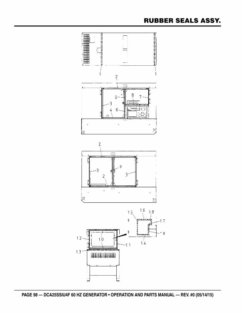
PAGE 98 — DCA25SSIU4F 60 HZ GENERATOR • OPERATION AND PARTS MANUAL — REV. #0 (05/14/15)
RUBBER SEALS ASSY.
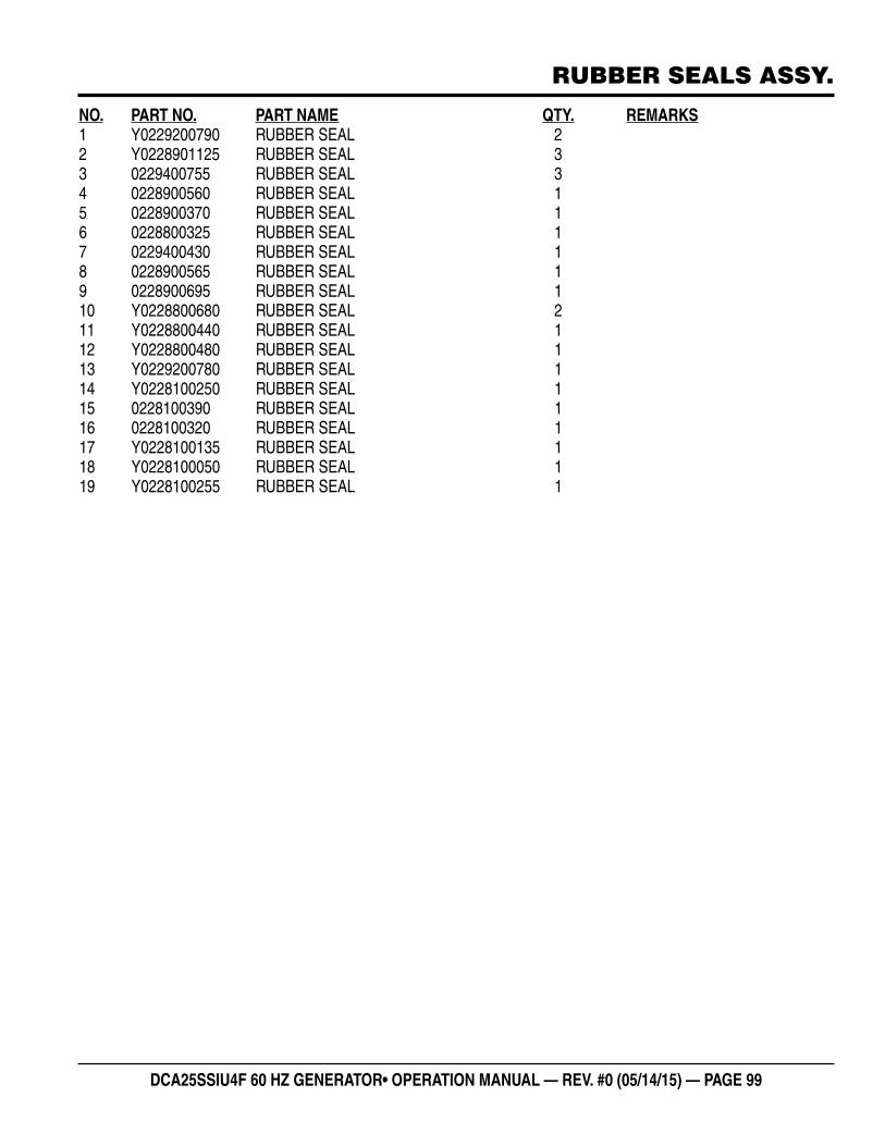
DCA25SSIU4F 60 HZ GENERATOR• OPERATION MANUAL — REV. #0 (05/14/15) — PAGE 99
RUBBER SEALS ASSY.
NO. PART NO. PART NAME QTY. REMARKS1 Y0229200790 RUBBER SEAL 22 Y0228901125 RUBBER SEAL 33 0229400755 RUBBER SEAL 34 0228900560 RUBBER SEAL 15 0228900370 RUBBER SEAL 16 0228800325 RUBBER SEAL 17 0229400430 RUBBER SEAL 18 0228900565 RUBBER SEAL 19 0228900695 RUBBER SEAL 110 Y0228800680 RUBBER SEAL 211 Y0228800440 RUBBER SEAL 112 Y0228800480 RUBBER SEAL 113 Y0229200780 RUBBER SEAL 114 Y0228100250 RUBBER SEAL 115 0228100390 RUBBER SEAL 116 0228100320 RUBBER SEAL 117 Y0228100135 RUBBER SEAL 118 Y0228100050 RUBBER SEAL 119 Y0228100255 RUBBER SEAL 1
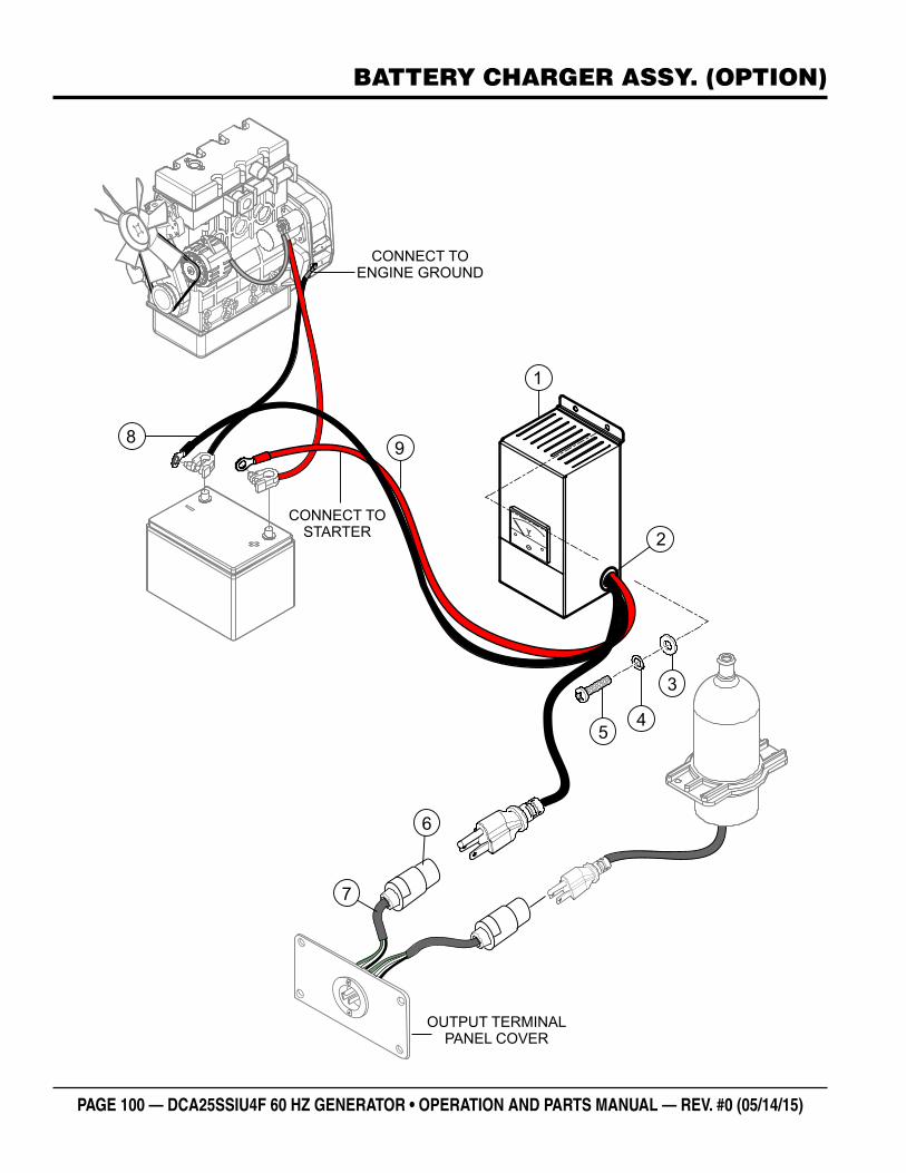
PAGE 100 — DCA25SSIU4F 60 HZ GENERATOR • OPERATION AND PARTS MANUAL — REV. #0 (05/14/15)
BATTERY CHARGER ASSY. (OPTION)
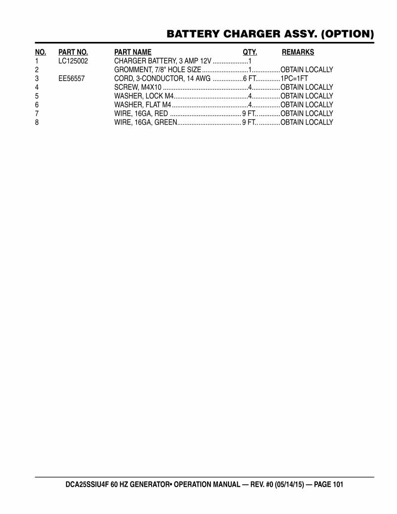
DCA25SSIU4F 60 HZ GENERATOR• OPERATION MANUAL — REV. #0 (05/14/15) — PAGE 101
BATTERY CHARGER ASSY. (OPTION)
NO. PART NO. PART NAME QTY. REMARKS1 LC125002 CHARGER BATTERY, 3 AMP 12V ....................12 GROMMENT, 7/8" HOLE SIZE ..........................1................OBTAIN LOCALLY3 EE56557 CORD, 3-CONDUCTOR, 14 AWG .................6 FT. .............1PC=1FT4 SCREW, M4X10 ................................................4................OBTAIN LOCALLY5 WASHER, LOCK M4..........................................4................OBTAIN LOCALLY6 WASHER, FLAT M4 ...........................................4................OBTAIN LOCALLY7 WIRE, 16GA, RED ........................................ 9 FT.. ............OBTAIN LOCALLY8 WIRE, 16GA, GREEN .................................... 9 FT.. ............OBTAIN LOCALLY
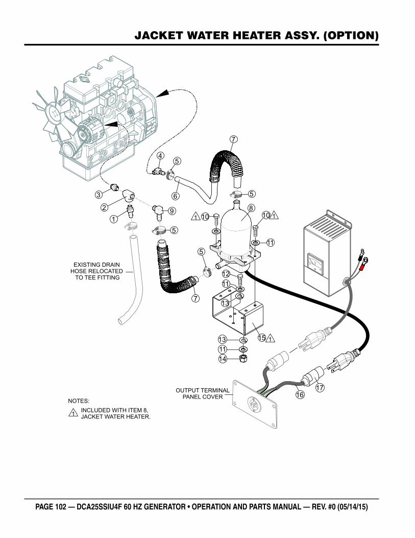
PAGE 102 — DCA25SSIU4F 60 HZ GENERATOR • OPERATION AND PARTS MANUAL — REV. #0 (05/14/15)
JACKET WATER HEATER ASSY. (OPTION)
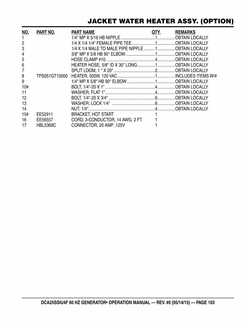
DCA25SSIU4F 60 HZ GENERATOR• OPERATION MANUAL — REV. #0 (05/14/15) — PAGE 103
JACKET WATER HEATER ASSY. (OPTION)
NO. PART NO. PART NAME QTY. REMARKS1 1/4" MP X 5/16 HB NIPPLE ...............................1................OBTAIN LOCALLY2 1/4 X 1/4 1/4" FEMALE PIPE TEE .....................1................OBTAIN LOCALLY3 1/4 X 1/4 MALE TO MALE PIPE NIPPLE ..........1................OBTAIN LOCALLY4 3/8" MP X 5/8 HB 90° ELBOW ...........................1................OBTAIN LOCALLY5 HOSE CLAMP #10 ............................................4................OBTAIN LOCALLY6 HEATER HOSE, 5/8" ID X 30" LONG ................1................OBTAIN LOCALLY7 SPLIT LOOM, 1 " X 20" .....................................2................OBTAIN LOCALLY8 TPS051GT10000 HEATER, 500W, 120 VAC ..................................1................INCLUDES ITEMS W/#9 1/4" MP X 5/8" HB 90° ELBOW .........................1................OBTAIN LOCALLY10# BOLT, 1/4"-20 X 1" .............................................4................OBTAIN LOCALLY11 WASHER, FLAT 1" .............................................4................OBTAIN LOCALLY12 BOLT, 1/4"-20 X 3/4" ..........................................6................OBTAIN LOCALLY13 WASHER, LOCK 1/4" .......................................6................OBTAIN LOCALLY14 NUT, 1/4" ............................................................4................OBTAIN LOCALLY15# EE52911 BRACKET, HOT START 116 EE56557 CORD, 3-CONDUCTOR, 14 AWG, 2 FT. 117 HBL5369C CONNECTOR, 20 AMP ,125V 1
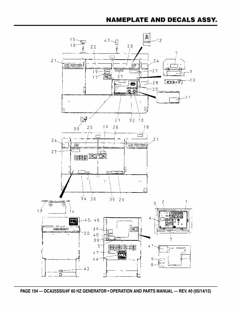
PAGE 104 — DCA25SSIU4F 60 HZ GENERATOR • OPERATION AND PARTS MANUAL — REV. #0 (05/14/15)
NAMEPLATE AND DECALS ASSY.
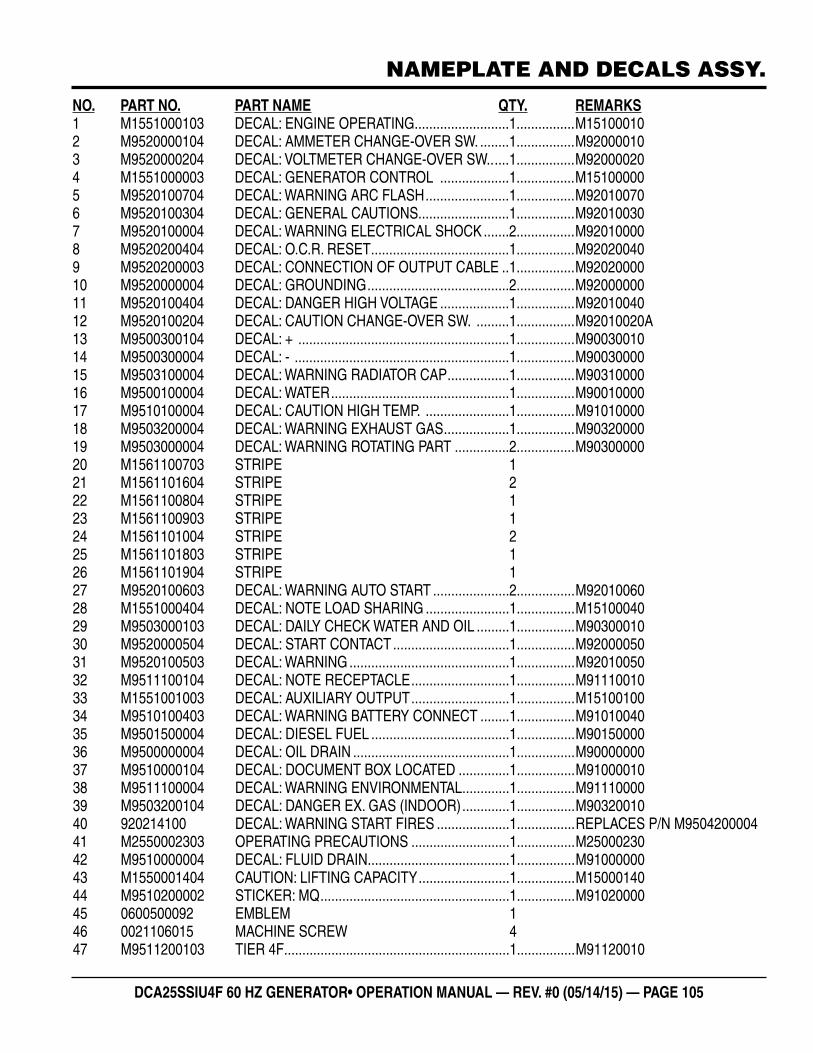
DCA25SSIU4F 60 HZ GENERATOR• OPERATION MANUAL — REV. #0 (05/14/15) — PAGE 105
NAMEPLATE AND DECALS ASSY.
NO. PART NO. PART NAME QTY. REMARKS1 M1551000103 DECAL: ENGINE OPERATING ..........................1................M151000102 M9520000104 DECAL: AMMETER CHANGE-OVER SW. ........1................M920000103 M9520000204 DECAL: VOLTMETER CHANGE-OVER SW.. ....1................M920000204 M1551000003 DECAL: GENERATOR CONTROL ...................1................M151000005 M9520100704 DECAL: WARNING ARC FLASH .......................1................M920100706 M9520100304 DECAL: GENERAL CAUTIONS.........................1................M920100307 M9520100004 DECAL: WARNING ELECTRICAL SHOCK .......2................M920100008 M9520200404 DECAL: O.C.R. RESET ......................................1................M920200409 M9520200003 DECAL: CONNECTION OF OUTPUT CABLE ..1................M9202000010 M9520000004 DECAL: GROUNDING .......................................2................M9200000011 M9520100404 DECAL: DANGER HIGH VOLTAGE ...................1................M9201004012 M9520100204 DECAL: CAUTION CHANGE-OVER SW. .........1................M92010020A13 M9500300104 DECAL: + ..........................................................1................M9003001014 M9500300004 DECAL: - ...........................................................1................M9003000015 M9503100004 DECAL: WARNING RADIATOR CAP .................1................M9031000016 M9500100004 DECAL: WATER .................................................1................M9001000017 M9510100004 DECAL: CAUTION HIGH TEMP. .......................1................M9101000018 M9503200004 DECAL: WARNING EXHAUST GAS ..................1................M9032000019 M9503000004 DECAL: WARNING ROTATING PART ...............2................M9030000020 M1561100703 STRIPE 121 M1561101604 STRIPE 222 M1561100804 STRIPE 123 M1561100903 STRIPE 124 M1561101004 STRIPE 225 M1561101803 STRIPE 126 M1561101904 STRIPE 127 M9520100603 DECAL: WARNING AUTO START .....................2................M9201006028 M1551000404 DECAL: NOTE LOAD SHARING .......................1................M1510004029 M9503000103 DECAL: DAILY CHECK WATER AND OIL .........1................M9030001030 M9520000504 DECAL: START CONTACT ................................1................M9200005031 M9520100503 DECAL: WARNING ............................................1................M9201005032 M9511100104 DECAL: NOTE RECEPTACLE ...........................1................M9111001033 M1551001003 DECAL: AUXILIARY OUTPUT ...........................1................M1510010034 M9510100403 DECAL: WARNING BATTERY CONNECT ........1................M9101004035 M9501500004 DECAL: DIESEL FUEL ......................................1................M9015000036 M9500000004 DECAL: OIL DRAIN ...........................................1................M9000000037 M9510000104 DECAL: DOCUMENT BOX LOCATED ..............1................M9100001038 M9511100004 DECAL: WARNING ENVIRONMENTAL .............1................M9111000039 M9503200104 DECAL: DANGER EX. GAS (INDOOR) .............1................M9032001040 920214100 DECAL: WARNING START FIRES ....................1................REPLACES P/N M950420000441 M2550002303 OPERATING PRECAUTIONS ...........................1................M2500023042 M9510000004 DECAL: FLUID DRAIN.......................................1................M9100000043 M1550001404 CAUTION: LIFTING CAPACITY .........................1................M1500014044 M9510200002 STICKER: MQ ....................................................1................M9102000045 0600500092 EMBLEM 146 0021106015 MACHINE SCREW 447 M9511200103 TIER 4F ..............................................................1................M91120010
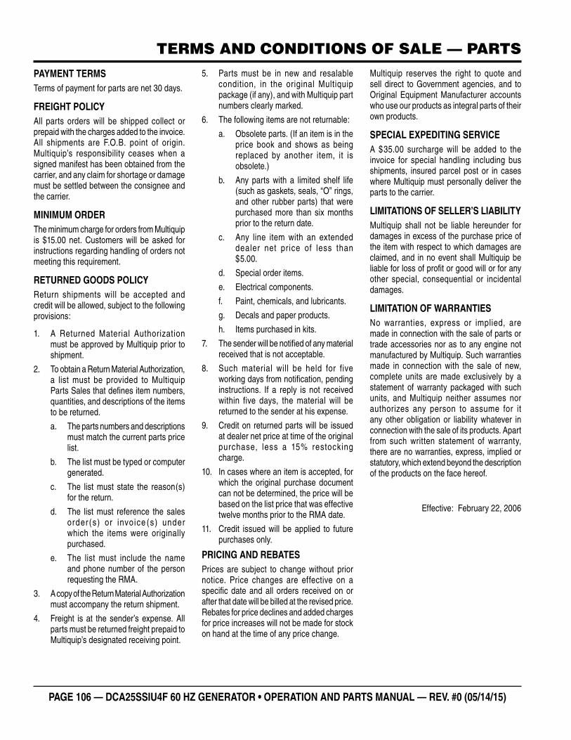
PAGE 106 — DCA25SSIU4F 60 HZ GENERATOR • OPERATION AND PARTS MANUAL — REV. #0 (05/14/15)
TERMS AND CONDITIONS OF SALE — PARTSPAYMENT TERMSTerms of payment for parts are net 30 days.
FREIGHT POLICYAll parts orders will be shipped collect or prepaid with the charges added to the invoice. All shipments are F.O.B. point of origin. Multiquip’s responsibility ceases when a signed manifest has been obtained from the carrier, and any claim for shortage or damage must be settled between the consignee and the carrier.
MINIMUM ORDERThe minimum charge for orders from Multiquip is $15.00 net. Customers will be asked for instructions regarding handling of orders not meeting this requirement.
RETURNED GOODS POLICYReturn shipments will be accepted and credit will be allowed, subject to the following provisions:
1. A Returned Material Authorization must be approved by Multiquip prior to shipment.
2. To obtain a Return Material Authorization, a list must be provided to Multiquip Parts Sales that defi nes item numbers, quantities, and descriptions of the items to be returned.
a. The parts numbers and descriptions must match the current parts price list.
b. The list must be typed or computer generated.
c. The list must state the reason(s) for the return.
d. The list must reference the sales order (s) or invoice (s) under which the items were originally purchased.
e. The list must include the name and phone number of the person requesting the RMA.
3. A copy of the Return Material Authorization must accompany the return shipment.
4. Freight is at the sender’s expense. All parts must be returned freight prepaid to Multiquip’s designated receiving point.
5. Parts must be in new and resalable condition, in the original Multiquip package (if any), and with Multiquip part numbers clearly marked.
6. The following items are not returnable:
a. Obsolete parts. (If an item is in the price book and shows as being replaced by another item, it is obsolete.)
b. Any parts with a limited shelf life (such as gaskets, seals, “O” rings, and other rubber parts) that were purchased more than six months prior to the return date.
c. Any line item with an extended dealer net price of less than $5.00.
d. Special order items.
e. Electrical components.
f. Paint, chemicals, and lubricants.
g. Decals and paper products.
h. Items purchased in kits.
7. The sender will be notifi ed of any material received that is not acceptable.
8. Such material will be held for five working days from notifi cation, pending instructions. If a reply is not received within five days, the material will be returned to the sender at his expense.
9. Credit on returned parts will be issued at dealer net price at time of the original purchase, less a 15% restocking charge.
10. In cases where an item is accepted, for which the original purchase document can not be determined, the price will be based on the list price that was effective twelve months prior to the RMA date.
11. Credit issued will be applied to future purchases only.
PRICING AND REBATESPrices are subject to change without prior notice. Price changes are effective on a specifi c date and all orders received on or after that date will be billed at the revised price. Rebates for price declines and added charges for price increases will not be made for stock on hand at the time of any price change.
Multiquip reserves the right to quote and sell direct to Government agencies, and to Original Equipment Manufacturer accounts who use our products as integral parts of their own products.
SPECIAL EXPEDITING SERVICEA $35.00 surcharge will be added to the invoice for special handling including bus shipments, insured parcel post or in cases where Multiquip must personally deliver the parts to the carrier.
LIMITATIONS OF SELLER’S LIABILITYMultiquip shall not be liable hereunder for damages in excess of the purchase price of the item with respect to which damages are claimed, and in no event shall Multiquip be liable for loss of profi t or good will or for any other special, consequential or incidental damages.
LIMITATION OF WARRANTIESNo warranties, express or implied, are made in connection with the sale of parts or trade accessories nor as to any engine not manufactured by Multiquip. Such warranties made in connection with the sale of new, complete units are made exclusively by a statement of warranty packaged with such units, and Multiquip neither assumes nor authorizes any person to assume for it any other obligation or liability whatever in connection with the sale of its products. Apart from such written statement of warranty, there are no warranties, express, implied or statutory, which extend beyond the description of the products on the face hereof.
Effective: February 22, 2006

DCA25SSIU4F 60 HZ GENERATOR• OPERATION MANUAL — REV. #0 (05/14/15) — PAGE 107
NOTES
OPERATION AND PARTS MANUAL
Your Local Dealer is:
HERE’S HOW TO GET HELPPLEASE HAVE THE MODEL AND SERIAL
NUMBER ON-HAND WHEN CALLING
United StateSMultiquip Corporate Office MQ Parts Department
18910 Wilmington Ave.Carson, CA 90746 Contact: [email protected]
Tel. (800) 421-1244Fax (310) 537-3927
800-427-1244310-537-3700
Fax: 800-672-7877Fax: 310-637-3284
Service Department Warranty Department
800-421-1244310-537-3700
Fax: 310-537-4259 800-421-1244310-537-3700
Fax: 310-943-2249
Technical Assistance
800-478-1244 Fax: 310-943-2238
Canada United Kingdom
Multiquip Multiquip (UK) Limited Head Office
4110 Industriel Boul.Laval, Quebec, Canada H7L 6V3Contact: [email protected]
Tel: (450) 625-2244 Tel: (877) 963-4411Fax: (450) 625-8664
Unit 2, Northpoint Industrial Estate, Globe Lane,Dukinfield, Cheshire SK16 4UJContact: [email protected]
Tel: 0161 339 2223 Fax: 0161 339 3226
© COPYRIGHT 2015, MULTIQUIP INC.
Multiquip Inc , the MQ logo and the MQ Power logo are registered trademarks of Multiquip Inc. and may not be used, reproduced, or altered without written permission. All other trademarks are the property of their respective owners and used with permission.
This manual MUST accompany the equipment at all times. This manual is considered a permanent part of the equipment and should remain with the unit if resold.
The information and specifi cations included in this publication were in effect at the time of approval for printing. Illustrations, descriptions, references and technical data contained in this manual are for guidance only and may not be considered as binding. Multiquip Inc. reserves the right to discontinue or change specifi cations, design or the information published in this publication at any time without notice and without incurring any obligations.
Manufactured for Multiquip Inc.
byDENYO CO., LTD, JAPAN