Embed Size (px)
Citation preview

PRODUCT DATA SHEET
PhlatLight® White LED Illumination Products
SST-90 Series
www.luminus.com © 2010 Luminus Devices, Inc. - All Rights ReservedLast Updated 2-9-10 PDS_001342 Rev 04
Features
• Extremely high optical output: Over 2,250 lumens from a single chip (white)
• Extremely high efficiency: Over 100 lumens per watt at 3.15A
• High thermal conductivity package - junction to case thermal resistance of only 0.64 °C/W
• Large, monolithic chip with uniform emitting area of 9 mm2
• Lumen maintenance of greater than 70% after 60,000 hours
• Environmentally friendly: RoHS compliant
• Variable drive currents: less than 1 A through 9 A to full reli-ability specifications.
• High reliability
• Electrically isolated thermal path
Applications
• Replacement Lamps
• Architectural Lighting
• Retail Lighting
• Residential Lighting
• Consumer Portable
• Spot Lighting
• High Bay Lighting
• Wide Area Lighting
• Street Lighting
PhlatLight® LEDs enable a new class of illumination applications.
Table of Contents
Technology Overview............................................ 2
Test Specifications............................................... 2
PhlatLight Bin Codes............................................. 3
Product Shipping and Labeling Information.................. 7
Optical and Electrical Characteristics ........................ 8
Spectral Characteristics........................................10
Radiation Patterns ..............................................11
Thermal Resistance.............................................12
Mechanical Dimensions - Emitter.............................13
Mechanical Dimensions - Star .................................14
Soldering Profile ................................................15
Ordering Information ...........................................16

SST-90 - Product Datasheet
© 2010 Luminus Devices, Inc. - All Rights ReservedPage 2
Technology Overview
PhlatLight LEDs benefit from a suite of innovations in the fields of chip technology, packaging, and thermal management. These break-throughs allow illumination designers to achieve efficient light engine designs and deliver high brightness solutions.
PhlatLight Technology
The name PhlatLight is derived from Photonic Lattice. Photoniclattice technology creates true surface emission from the source,which enables large area LED chips with uniform brightness overthe entire LED chip surface. The optical power and brightnessproduced by these large monolithic chips enable solutions whichreplace arc and halogen lamps where arrays of traditional highpower LEDs cannot.
Packaging Technology
Thermal management is critical in high power LED applications.With a thermal resistance from junction to case of 0.64°C/W,PhlatLight SST-90 devices have the lowest thermal resistance ofany LED on the market. This allows the LED to be driven at highercurrent densities while maintaining a low junction temperature,thereby resulting in brighter and longer lifetimes. The package iseasy to use, and ready to be mounted in the lighting system.
Reliability
Designed from the ground up, PhlatLight LEDs are one of the mostreliable light sources in the world today. PhlatLight LEDs havepassed a rigorous suite of environmental and mechanical stresstests, including mechanical shock, vibration, temperature cyclingand humidity, and have been fully qualified for use in extremehigh power and high current applications. With very low failurerates and median lifetimes that are well above 60,000 hours,PhlatLight LEDs are ready for the most demanding applications.
Environmental Benefits
PhlatLight LEDs help reduce power consumption and the amountof hazardous waste entering the environment. All PhlatLightproducts manufactured by Luminus are RoHS compliant and freeof hazardous materials, including lead and mercury.
Understanding PhlatLight Test Specifications
Every PhlatLight LED device is fully tested to ensure that it meets the high quality standards of Luminus’ products.
Multiple Operating Points (3.2 A, 9.0 A)
The tables on the following pages provide typical optical andelectrical characteristics. Since the LEDs can be operated over awide range of drive conditions (currents from less than 1.0 A to9.0 A, and duty cycle from <1% to 100%) multiple drive conditionsare listed.
PhlatLight SST-90 devices are production tested at 3.2 A. The val-ues shown at 9.0 A are for additional reference at other possibledrive conditions.

SST-90 - Product Datasheet
© 2010 Luminus Devices, Inc. - All Rights ReservedPage 3
PhlatLight White Binning Structure
PhlatLight SST-90 White LEDs are tested for luminous flux and chromaticity at a drive current of 3.15A and placed into one of the fol-lowing luminous flux (FF) and chromaticity (WW) bins:
For ordering information, please refer to page 16 or PDS-001393: PhlatLight Binning and Labeling.
Flux Bins (TJ = 25 ºC)
Color Flux Bin (FF) Minimum Flux (lm)@ 3.15 A
Maximum Flux (lm)@ 3.15 A
W65S6500K, Standard CRI (typ. 70)
WL 700 850
WM 850 1,000
WN 1,000 1,200
W57S5700K, Standard CRI (typ. 70)
WL 700 850
WM 850 1,000
WN 1,000 1,200
W45S4500K, Standard CRI, (typ. 70)
WL 700 850
WM 850 1,000
WN 1,000 1,200
W40M4000K, Moderate CRI, (typ. 83)
WJ 500 600
WK 600 700
WL 700 850
W30M3000K, Moderate CRI, (typ. 83)
WJ 500 600
WK 600 700
WL 700 850

SST-90 - Product Datasheet
© 2010 Luminus Devices, Inc. - All Rights ReservedPage 4
Luminus’ Standard Chromaticity Bins: 1931 CIE Curve
6500K
5700K
5000K
4500K
4000K
3500K
3000K
2700K
0.470
0.445
0.420
0.395
0.370
0.345
0.320
0.295
0.2700.275 0.300
CIEx
0.325 0.350 0.375 0.400 0.425 0.450 0.475 0.500
CIEy
BB Locus
DE
EF
EH
EK
EN
EQ
ES
EU
EW
W4Y4
Y3W3
U4V4
V3U3
S4
S3
T4
T3
DT
DVDYQ4
R4
Q3
R3
DR
N4
P4
N3P3
DP
K4
M4
K3M3
DM
H4
J4
H3
J3
DJF4
G4
G3
F3
DF
DG
Chromaticity Bins
SST-90 - Product Datasheet
© 2010 Luminus Devices, Inc. - All Rights ReservedPage 5
6500K Chromaticity Bins
Bin Code (WW) CIEx CIEy
DG
0.307 0.3110.322 0.3260.323 0.3160.309 0.302
F3*
0.305 0.3210.313 0.3290.315 0.3190.307 0.311
F4*
0.303 0.3300.312 0.3390.313 0.3290.305 0.321
G3*
0.313 0.3290.321 0.3370.322 0.3260.315 0.319
G4*
0.312 0.3390.321 0.3480.321 0.3370.313 0.329
EF
0.302 0.3350.320 0.3540.321 0.3480.303 0.330
DE
0.283 0.3040.303 0.3300.307 0.3110.289 0.293
DF
0.289 0.2930.307 0.3110.309 0.3020.293 0.285
5700K Chromaticity Bins
Bin Code (WW) CIEx CIEy
DJ
0.322 0.3240.337 0.3370.336 0.3260.323 0.314
H3*
0.321 0.3350.329 0.3420.329 0.3310.322 0.324
H4*
0.321 0.3460.329 0.3540.329 0.3420.321 0.335
J3*
0.329 0.3420.337 0.3490.337 0.3370.330 0.331
J4*
0.329 0.3540.338 0.3620.337 0.3490.329 0.342
EH
0.320 0.3520.338 0.3680.338 0.3620.321 0.346
5000K Chromaticity Bins
Bin Code (WW) CIEx CIEy
EK
0.338 0.3680.356 0.3840.355 0.3760.338 0.362
K3*
0.337 0.3490.345 0.3550.345 0.3430.337 0.337
K4*
0.338 0.3620.347 0.3690.345 0.3550.337 0.349
M3*
0.345 0.3550.353 0.3620.352 0.3490.344 0.343
M4*
0.346 0.3690.355 0.3760.353 0.3620.345 0.355
DM
0.337 0.3370.352 0.3490.350 0.3370.336 0.326
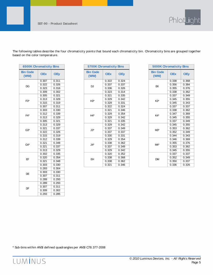
The following tables describe the four chromaticity points that bound each chromaticity bin. Chromaticity bins are grouped togetherbased on the color temperature.
* Sub-bins within ANSI defined quadrangles per ANSI C78.377-2008

SST-90 - Product Datasheet
© 2010 Luminus Devices, Inc. - All Rights ReservedPage 6
4500k Chromaticity Bins
Bin Code (WW) CIEx CIEy
EN
0.356 0.3840.376 0.3960.374 0.3870.355 0.374
N3*
0.353 0.3600.361 0.3660.359 0.3520.351 0.347
N4*
0.355 0.3740.364 0.3810.361 0.3660.353 0.360
P3*
0.361 0.3660.370 0.3730.367 0.3580.359 0.352
P4*
0.364 0.3810.374 0.3870.370 0.3730.361 0.366
DP
0.351 0.3470.367 0.3580.364 0.3460.350 0.335
3000K Chromaticity Bins
Bin Code (WW) CIEx CIEy
EU
0.435 0.4270.462 0.4370.456 0.4260.430 0.417
U3*
0.422 0.3990.434 0.4030.426 0.3850.415 0.381
U4*
0.430 0.4170.443 0.4210.434 0.4030.422 0.399
V3*
0.434 0.4030.447 0.4080.437 0.3890.426 0.385
V4*
0.443 0.4210.456 0.4260.447 0.4080.434 0.403
DV
0.415 0.3810.437 0.3890.431 0.3770.409 0.369
4000K Chromaticity Bins
Bin Code (WW) CIEx CIEy
EQ
0.376 0.3960.404 0.4140.401 0.4040.374 0.387
Q3*
0.370 0.3730.382 0.3800.378 0.3650.367 0.358
Q4*
0.374 0.3870.387 0.3960.382 0.3800.370 0.373
R3*
0.382 0.3800.395 0.3880.390 0.3720.378 0.365
R4*
0.387 0.3960.401 0.4040.395 0.3880.382 0.380
DR
0.367 0.3580.390 0.3720.386 0.3590.364 0.346
2700K Chromaticity Bins
Bin Code (WW) CIEx CIEy
EW
0.462 0.4370.488 0.4440.481 0.4320.456 0.426
W3*
0.447 0.4080.458 0.4100.448 0.3920.437 0.389
W4*
0.456 0.4260.469 0.4290.458 0.4100.447 0.408
Y3*
0.458 0.4100.470 0.4130.459 0.3940.448 0.392
Y4*
0.469 0.4290.481 0.4320.470 0.4130.458 0.410
DY
0.437 0.3890.459 0.3940.452 0.3820.431 0.377
3500K Chromaticity Bins
Bin Code (WW) CIEx CIEy
ES
0.403 0.4110.435 0.4270.430 0.4170.400 0.402
S3*
0.394 0.3850.407 0.3920.402 0.3750.389 0.369
S4*
0.400 0.4020.415 0.4090.407 0.3920.394 0.385
T3*
0.407 0.3920.422 0.3990.415 0.3810.402 0.375
T4*
0.415 0.4090.430 0.4170.422 0.3990.407 0.392
DT
0.389 0.3690.415 0.3810.409 0.3690.385 0.357
* Sub-bins within ANSI defined quadrangles per ANSI C78.377-2008
SST-90 - Product Datasheet
© 2010 Luminus Devices, Inc. - All Rights ReservedPage 7
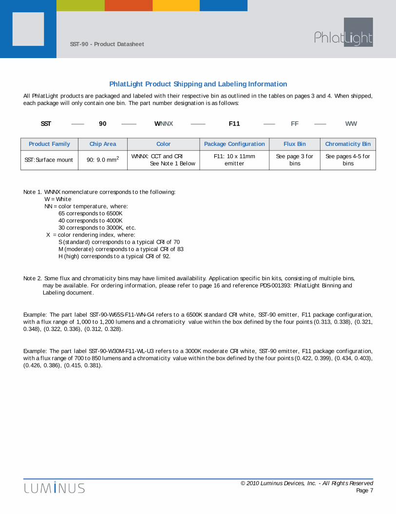
PhlatLight Product Shipping and Labeling Information
All PhlatLight products are packaged and labeled with their respective bin as outlined in the tables on pages 3 and 4. When shipped,each package will only contain one bin. The part number designation is as follows:
Note 1. WNNX nomenclature corresponds to the following: W = White NN = color temperature, where: 65 corresponds to 6500K 40 corresponds to 4000K 30 corresponds to 3000K, etc. X = color rendering index, where: S (standard) corresponds to a typical CRI of 70 M (moderate) corresponds to a typical CRI of 83 H (high) corresponds to a typical CRI of 92.
Note 2. Some flux and chromaticity bins may have limited availability. Application specific bin kits, consisting of multiple bins, may be available. For ordering information, please refer to page 16 and reference PDS-001393: PhlatLight Binning and Labeling document.
Example: The part label SST-90-W65S-F11-WN-G4 refers to a 6500K standard CRI white, SST-90 emitter, F11 package configuration,with a flux range of 1,000 to 1,200 lumens and a chromaticity value within the box defined by the four points (0.313, 0.338), (0.321,0.348), (0.322, 0.336), (0.312, 0.328).
Example: The part label SST-90-W30M-F11-WL-U3 refers to a 3000K moderate CRI white, SST-90 emitter, F11 package configuration,with a flux range of 700 to 850 lumens and a chromaticity value within the box defined by the four points (0.422, 0.399), (0.434, 0.403),(0.426, 0.386), (0.415, 0.381).
SST 90 WNNX F11 FF WW
Product Family Chip Area Color Package Configuration Flux Bin Chromaticity Bin
SST:Surface mount 90: 9.0 mm2 WNNX: CCT and CRI See Note 1 Below
F11: 10 x 11mm emitter
See page 3 for bins
See pages 4-5 for bins

SST-90 - Product Datasheet
© 2010 Luminus Devices, Inc. - All Rights ReservedPage 8
Optical and Electrical Characteristics (TJ = 25 ºC)
White
Drive Condition1 3.15 A 9.0 A
Parameter Symbol Typical Values at Test Current
Values at Indicated Currents2 Unit
Current Density j 0.35 1.0 A/mm2
Forward Voltage
VF, min 2.50
VF, typ 3.25 3.87 V
VF, max 3.90
Common CharacteristicsSymbol Values Unit
Viewing Angle 2θ1/2 100 degrees
Emitting Area 9.0 mm2
Emitting Area Dimensions 3 x 3 mmxmm
Forward Voltage Temperature Coefficient3 -2.45 mV/ºC
Absolute Maximum RatingsSymbol Values Unit
Maximum Current4 9 A
Maximum Reverse Current Not Allowed A
Maximum Junction Temperature5 Tj-max 150 ºC
Storage Temperature Range -40/+100 ºC
Note 1: Listed drive conditions are typical for common applications. PhlatLight SST-90-W devices can be driven at currents ranging from <1A to 9A and at duty cycles ranging from <1% to 100%. Drive current and duty cycle should be adjusted as necessary to maintain the junction temperature desired to meet application lifetime requirements.
Note 2: Unless otherwise noted, values listed are typical.Note 3: Forward voltage temperature coefficient at 3.15 A. Contact Luminus for value at other drive conditions.Note 4: Luminus PhlatLight SST-90-W LEDs are designed for operation to an absolute maximum forward drive current of 9 A. Product
lifetime data is specified at recommended forward drive currents. Sustained operation at absolute maximum currents will result in a reduction of device lifetime compared to recommended forward drive currents. Actual device lifetimes will also depend on junction temperature. Refer to the APN-001522: Reliability Application Note for SST-90-W for further information. In pulsed operation, rise time from 10-90% of forward current should be larger than 0.5 microseconds.
Note 5: Lifetime dependent on LED junction temperature . Thermal calculations based on input power and thermal management system should be performed to ensure Tj is maintained below Tjmax rating or life will be reduced. Refer to APN-001522 for further information.
Note 6: CIE measurement uncertainty for white devices is estimated to be +/- 0.01.Note 7: Special design considerations must be observed for operation under 1 A. Please contact Luminus for further information.Note 8: Caution must be taken not to stare at the light emitted from these LEDs. Under special circumstances, the high intensity could
damage the eye.

SST-90 - Product Datasheet
© 2010 Luminus Devices, Inc. - All Rights ReservedPage 9
Relative Luminous Flux vs. Forward Current (TJ = 25 ºC)1
Forward Current vs. Forward Voltage (TJ = 25 ºC)
Note1. Yellow squares indicate typical operating conditions
0%
50%
100%
150%
200%
250%
300%
0.0 1.0 2.0 3.0 4.0 5.0 6.0 7.0 8.0 9.0
Forward Current (A)
Rela
tive
Lum
inou
s Fl
ux (
%)
0.0
1.0
2.0
3.0
4.0
5.0
6.0
7.0
8.0
9.0
0.0 0.5 1.0 1.5 2.0 2.5 3.0 3.5 4.0 4.5
Forward Voltage (V)
Forw
ard
Cur
rent
(A
)

SST-90 - Product Datasheet
© 2010 Luminus Devices, Inc. - All Rights ReservedPage 10
Relative Output Flux vs. Junction Temperature (IF = 3.15 A)
Typical Relative Spectral Power (TJ = 25ºC)
0%
10%
20%
30%
40%
50%
60%
70%
80%
90%
100%
25 50 75 100 125 150
Junction Temperature (°C)
Rela
tive
Lum
inou
s Fl
ux (
%)
0%
10%
20%
30%
40%
50%
60%
70%
80%
90%
100%
400 450 500 550 600 650 700 750
Wavelength (nm)
Rela
tive
Spe
ctra
l Po
wer
Dis
trib
utio
n (%
)
6500K CCT4500K CCT3000K CCT

SST-90 - Product Datasheet
© 2010 Luminus Devices, Inc. - All Rights ReservedPage 11
Typical Polar Radiation Pattern
Typical Angular Radiation Pattern
30°
60° 300°
330°
-120% -100% -80% -60% -40% -20% 0% 20% 40% 60% 80% 100% 120%
0%
20%
40%
60%
80%
100%
120%
-90 -75 -60 -45 -30 -15 0 15 30 45 60 75 90
Angular Displacement (degrees)
Rela
tive
Inte
nsit
y (%
)

SST-90 - Product Datasheet
© 2010 Luminus Devices, Inc. - All Rights ReservedPage 12
Thermal Resistance
Typical Thermal Resistance
Rj-c1
Note 1: Thermal resistance values are based on FEA model results cor-related to measured Rθj-hs data.
0.64 ºC/W
Rj-b1 2.02 °C/W
Rj-hs2
Note 2: Thermal resistance is measured using a SAC305 solder, a Bergquist Al-clad MCPCB, and eGraf 1205 thermal interface material.
2.15 ºC/W
Ths definition = 3 mm from core-board

© 2010 Luminus Devices, Inc. - All Rights ReservedPage 13
SST-90 - Product Datasheet
For detailed drawing please refer to DWG-001359 document
Mechanical Dimensions - SST-90 Emitter

© 2010 Luminus Devices, Inc. - All Rights ReservedPage 14
SST-90 - Product Datasheet
Mechanical Dimensions - SST-90 Star
PhlatLight SST-90-W devices are available on a star board for prototyping purposes. Please see page 16 for ordering information.
Notes:1. Recommended mounting screw: M3 or #42. All dimensions in millimeters3. All anode pads on board are interconnected. All cathode pads on board are interconnected

SST-90 - Product Datasheet
© 2010 Luminus Devices, Inc. - All Rights ReservedPage 15
Reflow Soldering Characteristics
Solder profile guideline
Note: 1. Temperatures are taken and monitored at the component copper layerNote: 2. Optimum profile may differ due to oven type, circuit board or assembly layoutNote: 3. Recommended lead free, no-clean solder: AIM NC254-SAC305Note: 4. Refer to APN-001473: PhlatLight Soldering and Handling application note for additional solder profiles and details.
Solder Profile Stage Lead-free solder Lead-based solder
Profile Length, Ambient to Peak 2.75 - 3.5 minutes 2.75 - 3.5 minutes
Time Maintained Above: Temperature 217 ºC 183 ºC
Time Maintained Above: Time 30 - 60 seconds 30-60 seconds
Cooldown Rate ≤ 4º C/sec ≤ 4º C/sec
Cooldown Duration 45 ± 15 sec 45 ± 15 sec

SST-90 - Product Datasheet
© 2010 Luminus Devices, Inc. - All Rights ReservedPage 16
Ordering Information
Ordering Part Number1,2
Note 1: GL150 - denotes a bin kit comprising of all flux and chromaticity bins at the 6500K and 5700K color pointsGL350 - denotes a bin kit comprising of all flux and chromaticity bins at the 5000K and 4500K color pointsGJ550 - denotes a bin kit comprising of all flux and chromaticity bins at the 4000K and 3500K color pointsGJ750 - denotes a bin kit comprising of all flux and chromaticity bins at the 3000K and 2700K color pointsSee PDS-001393: PhlatLight Binning and Labeling document for more information.
Note 2: For ordering information on all available bin kits, please see PDS-001393: PhlatLight Binning and Labeling document.
Color Description
SST-90-WDLS-F11-GL1506500K White5700K White
White PhlatLight SST-90 surface mount device consisting of a domed 9mm2 LED mounted on a ceramic substrate.
SST-90-WCLS-F11-GL3505000K White4500K White
White PhlatLight SST-90 surface mount device consisting of a domed 9mm2 LED mounted on a ceramic substrate.
SST-90-WWTS-F11-GJ5504000K White3500K White
White PhlatLight SST-90 surface mount device consisting of a domed 9mm2 LED mounted on a ceramic substrate.
SST-90-WWRM-F11-GJ7503000K White2700K White
White PhlatLight SST-90 surface mount device consisting of a domed 9mm2 LED mounted on a ceramic substrate.
SSR-90-WDLS-R11-GL1506500K White5700K White
PhlatLight SSR-90 evaluation module consisting of a SST-90 surface mount device mounted on an aluminum star board.
SSR-90-WCLS-R11-GL3505000K White4500K White
PhlatLight SSR-90 evaluation module consisting of a SST-90 surface mount device mounted on an aluminum star board.
SSR-90-WWTS-R11-GJ5504000K White3500K White
PhlatLight SSR-90 evaluation module consisting of a SST-90 surface mount device mounted on an aluminum star board.
SSR-90-WWRM-R11-GJ7503000K White2700K White
PhlatLight SSR-90 evaluation module consisting of a SST-90 surface mount device mounted on an aluminum star board.

SST-90 - Product Datasheet
© 2010 Luminus Devices, Inc. - All Rights ReservedPage 17
www.luminus.com
The products, their specifications and other information appearing in this document are subject to change by Luminus Devices without notice. Luminus
Devices assumes no liability for errors that may appear in this document, and no liability otherwise arising from the application or use of the product
or information contained herein. None of the information provided herein should be considered to be a representation of the fitness or suitability of
the product for any particular application or as any other form of warranty. Luminus Devices’ product warranties are limited to only such warranties as
accompany a purchase contract or purchase order for such products. Nothing herein is to be construed as constituting an additional warranty. No infor-
mation contained in this publication may be considered as a waiver by Luminus Devices of any intellectual property rights that Luminus Devices may
have in such information. PhlatLight® is a registered trademark of Luminus Devices, Inc., all rights reserved.
This product is protected by U.S. Patents 6,831,302; 7,074,631; 7,083,993; 7,084,434; 7,098,589; 7,105,861; 7,138,666; 7,166,870; 7,166,871;
7,170,100; 7,196,354; 7,211,831; 7,262,550; 7,274,043; 7,301,271; 7,341,880; 7,344,903; 7,345,416; 7,348,603; 7,388,233; 7,391,059; Patents Pend-
ing in the U.S. and other countries.


![A Dimensions: [mm] B Recommended land pattern: [mm] · 2020. 8. 11. · 2014-03-11 2013-12-19 2013-12-04 2013-04-10 2013-03-06 2013-02-14 2012-12-10 DATE SSt SSt SSt SSt SSt SSt SSt](https://img.pdfslide.net/doc/110x75/6145e75a8f9ff812541fec6f/a-dimensions-mm-b-recommended-land-pattern-mm-2020-8-11-2014-03-11-2013-12-19.jpg)


![A Dimensions: [mm] B Recommended land pattern: [mm] D ... · 2005-12-16 DATE SSt SSt SSt SSt SSt SSt SSt BY SSt SSt SMu SMu SSt ... RDC Value 600 800 1000 0.20 High Cur rent ... 350](https://img.pdfslide.net/doc/110x75/5c61318009d3f21c6d8cb002/a-dimensions-mm-b-recommended-land-pattern-mm-d-2005-12-16-date-sst.jpg)