Embed Size (px)
Citation preview

CAR 2 CAR Communication Consortium
C2CCC_WP_2091_ Co-ChannelCoexistence_ MitigationMethods_V1.0 27/04/2021 Page 1 of 62
White paper on ITS-G5 and Sidelink LTE-V2X
Co-Channel Coexistence Mitigation Methods
About the C2C-CC
Enhancing road safety and traffic efficiency by means of Cooperative Intelligent Transport Systems and Services (C-ITS) is the dedicated goal of the CAR 2 CAR Communication Consortium. The industrial driven, non-commercial association was founded in 2002 by vehicle manufacturers affiliated with the idea of cooperative road traffic based on Vehicle-to-Vehicle Communications (V2V) and supported by Vehicle-to-Infrastructure Communications (V2I). The Consortium members represent worldwide major vehicle manufactures, equipment suppliers and research organisations.
Over the years, the CAR 2 CAR Communication Consortium has evolved to be one of the key players in preparing the initial deployment of C-ITS in Europe and the subsequent innovation phases. CAR 2 CAR members focus on wireless V2V communication applications based on ITS-G5 and concentrate all efforts on creating standards to ensure the interoperability of cooperative systems, spanning all vehicle classes across borders and brands. As a key contributor, the CAR 2 CAR Communication Consortium works in close cooperation with the European and international standardisation organisations such as ETSI and CEN.
Disclaimer
The present document has been developed within the CAR 2 CAR Communication Consortium and might be further elaborated within the CAR 2 CAR Communication Consortium. The CAR 2 CAR Communication Consortium and its members accept no liability for any use of this document and other documents from the CAR 2 CAR Communication Consortium for implementation. CAR 2 CAR Communication Consortium documents should be obtained directly from the CAR 2 CAR Communication Consortium. Copyright Notification: No part may be reproduced except as authorized by written permission. The copyright and the foregoing restriction extend to reproduction in all media. © 2021, CAR 2 CAR Communication Consortium.
CAR 2 CAR Communication Consortium
C2CCC_WP_2091_ Co-ChannelCoexistence_ MitigationMethods_V1.0 27/04/2021 Page 2 of 62
Document information
Number: 2091 Version: 1.0 Date: 27/04/2021
Title: ITS-G5 and Sidelink LTE-V2X Co-Channel Coexistence Mitigation Methods
Document Type:
White Paper
Release:
Release Status:
Published
Status: Final

CAR 2 CAR Communication Consortium
C2CCC_WP_2091_ Co-ChannelCoexistence_ MitigationMethods_V1.0 27/04/2021 Page 3 of 62
Changes since last version
Title: ITS-G5 and Sidelink LTE-V2X Co-Channel Coexistence Mitigation Methods
Date Changes Edited by Approved
27/4/2021 Initial release Release Management Steering Committee
Table 1: Changes since last version

CAR 2 CAR Communication Consortium
C2CCC_WP_2091_ Co-ChannelCoexistence_ MitigationMethods_V1.0 27/04/2021 Page 4 of 62
Content About the C2C-CC........................................................................................................................ 1 Disclaimer ...................................................................................................................................... 1
Document information .................................................................................................................. 2 Changes since last version ......................................................................................................... 3
Content ........................................................................................................................................... 4 List of figures ................................................................................................................................. 5
List of tables .................................................................................................................................. 7 Abbreviations ................................................................................................................................. 8
Executive summary ...................................................................................................................... 9
1 Introduction ........................................................................................................................... 12 1.1 Abstract.......................................................................................................................... 12
1.2 Survey of document ..................................................................................................... 14
2 The proposed mitigation methods .................................................................................... 15
2.1 Introduction ................................................................................................................... 15
2.2 Preliminary considerations on the coexistence methods ...................................... 15 2.2.1 Superframe and slots .................................................................................................................... 16 2.2.2 Static, semi-static, dynamic configuration of the superframe .................................................. 17 2.2.3 Definition of the time slot boundaries in the dynamic configuration ....................................... 18 2.2.4 The LTE “last symbol gap” issue ................................................................................................. 18
2.3 Mitigation methods ....................................................................................................... 19 2.3.1 Mitigation method A ....................................................................................................................... 19 2.3.2 Mitigation method B ....................................................................................................................... 21 2.3.3 Mitigation method C ....................................................................................................................... 22 2.3.4 Mitigation method D ....................................................................................................................... 23 2.3.5 Mitigation method E ....................................................................................................................... 24 2.3.6 Mitigation method F ....................................................................................................................... 24
2.4 Summary of the mitigation methods ......................................................................... 25 3 Simulator and Settings ....................................................................................................... 28
3.1 Introduction ................................................................................................................... 28
3.2 Summary of settings .................................................................................................... 28 3.3 Scenarios ...................................................................................................................... 29
3.4 Main settings and models ........................................................................................... 30 3.5 Assumptions related to the methods ........................................................................ 32
3.5.1 Assumptions related to method A ................................................................................................ 32 3.5.2 Assumptions related to method B ................................................................................................ 32 3.5.3 Assumptions related to method C................................................................................................ 33 3.5.4 Assumptions related to method F ................................................................................................ 33
3.6 Output metrics .............................................................................................................. 33 4 Results .................................................................................................................................. 35
4.1 Introduction ................................................................................................................... 35
4.2 Baseline Results .......................................................................................................... 35 4.3 Results with static configurations .............................................................................. 38
4.3.1 Results with static and semi-static methods .............................................................................. 38 4.3.2 Impact of synchronization ............................................................................................................. 41 4.3.3 Impact of erroneous technology proportion settings from the supervising entity ................. 42
4.4 Results with dynamic configurations ......................................................................... 43 4.4.1 Results assuming the basic versions with dynamic configuration .......................................... 43 4.4.2 On the relevance of the ITS-G5 header insertion to LTE-V2X in dynamic method C ......... 45
4.5 Comparison between static/semi-static and dynamic configurations .................. 46 4.5.1 Results with the best static/semi-static and dynamic mitigation methods ............................. 46 4.5.2 Results with legacy ITS-G5 .......................................................................................................... 49
5 Conclusion ............................................................................................................................ 50 Annex A – Details about the technology percentage evaluation ........................................ 53

CAR 2 CAR Communication Consortium
C2CCC_WP_2091_ Co-ChannelCoexistence_ MitigationMethods_V1.0 27/04/2021 Page 5 of 62
A.1 Introduction ....................................................................................................................... 53
A.2 Calculation of 𝑪𝑩𝑹𝑳𝑻𝑬 and 𝑪𝑩𝑹𝑳𝑻𝑬 + 𝑰𝑻𝑺𝑮𝟓 .......................................................... 53
A.3 Calculation of 𝑻𝒑𝒆𝒓 and LTE-V2X time slot duration ................................................. 53
A.4 Effectiveness of the technology percentage estimation ............................................ 54
Annex B – Details about the models implemented in LTEV2Vsim ..................................... 57 B.1 Decentralized congestion control .................................................................................. 57
B.2 Modeling the packet losses ............................................................................................ 57 B.3 Modeling short but strong interference in ITS-G5 ...................................................... 58
Annex C: Definition and applicability of backward compatibility ......................................... 60
Annex D – References ............................................................................................................... 61
List of figures Fig. 1-1: Illustration of access to medium by ITS-G5 ............................................................ 12
Fig. 1-2: Illustration of access to medium from a C-ITS-S for LTE-V2X ............................ 13
Fig. 1-3: Maximum range with PRR at 90% for ITS-G5 (left) and LTE-V2X (right) for different levels of density and percentage of ITS-G5 and LTE-V2X C-ITS-Ss. The range is normalized to the maximum value obtained with each technology, i.e., corresponding to the low density scenario with a single technology. ........................................................... 14
Fig. 2-1: Example of superframe structure ............................................................................. 16
Fig. 2-2: Static superframe configuration ................................................................................ 17
Fig. 2-3: Semi-static superframe configuration ...................................................................... 18 Fig. 2-4: Dynamic superframe configuration .......................................................................... 18
Fig. 2-5: Illustration of a superframe with three ITS-G5 and three LTE-V2X C-ITS-Ss transmitting under Method A ..................................................................................................... 20 Fig. 2-6: Example of channel rush problem occurrence under method A ......................... 20
Fig. 2-7: Example of the solution to the channel rush problem in enhanced method A .. 21 Fig. 2-8 Example illustration of a superframe with three ITS-G5 and three LTE-V2X C-ITS-Ss transmitting under method B ....................................................................................... 22
Fig. 2-9 Example illustration of a superframe with three ITS-G5 and three LTE-V2X C-ITS-Ss transmitting under method C ....................................................................................... 23
Fig. 2-10 Example illustration of a superframe with three ITS-G5 and three LTE-V2X C-ITS-Ss transmitting under method D ....................................................................................... 24 Fig. 2-11 Example illustration of a superframe with three ITS-G5 and three LTE-V2X C-ITS-Ss transmitting under method E ....................................................................................... 24
Fig. 2-12 Example illustration of a superframe with three ITS-G5 and three LTE-V2X C-ITS-Ss transmitting under method F........................................................................................ 25 Fig. 3-1: Average speed and average packets per vehicle per second vs. vehicle density ....................................................................................................................................................... 30
Fig. 3-2: Median CBR in all scenarios when either technology (alone) is used, assuming packets of 350 bytes .................................................................................................................. 30
Fig. 3-3: PER vs. SINR curves used in the simulations ....................................................... 32
Fig. 4-1: Baseline, low density. PRR vs. distance ................................................................. 36
Fig. 4-2: Baseline, medium density. PRR vs. distance ......................................................... 36 Fig. 4-3: Baseline, high density. PRR vs. distance ............................................................... 36 Fig. 4-4: Baseline, congested. PRR vs. distance .................................................................. 36
Fig. 4-5: Baseline, high density. Ccdf of DA ........................................................................... 37 Fig. 4-6: Baseline, high density. Ccdf of EED ........................................................................ 37
Fig. 4-7: Baseline, high density. Ccdf of IPG ......................................................................... 37 Fig. 4-8: Baseline, high density. WBSP .................................................................................. 38
Fig. 4-9: Static with ideal slots, medium density, 75% ITS-G5. PRR vs. distance ........... 39

CAR 2 CAR Communication Consortium
C2CCC_WP_2091_ Co-ChannelCoexistence_ MitigationMethods_V1.0 27/04/2021 Page 6 of 62
Fig. 4-10: Static with ideal slots, medium density, 50%-50%. PRR vs. distance ............. 40
Fig. 4-11: Static with ideal slots, medium density, 75% LTE-V2X. PRR vs. distance ..... 40 Fig. 4-12: Static with ideal slots, high density, 75% ITS-G5. PRR vs. distance ............... 40
Fig. 4-13: Static with ideal slots, high density, 50%-50%. PRR vs. distance .................... 40 Fig. 4-14: Static with ideal slots, high density, 75% LTE-V2X. PRR vs. distance ............ 41 Fig. 4-15: Static with ideal slots, medium density, 50%-50%, with ideal synchronization or with a uniformly distributed synchronization error of ITS-G5 C-ITS-Ss between -0.1 ms and +0.1 ms. PRR vs. distance ......................................................................................... 41
Fig. 4-16: Static with ideal slots, high density, 50%-50%, with ideal synchronization or with a uniformly distributed synchronization error of ITS-G5 C-ITS-Ss between -0.1 ms and +0.1 ms. PRR vs. distance ................................................................................................ 42 Fig. 4-17: (Semi-)static with ideal or imbalanced traffic, medium density, 50%-50%. PRR vs. distance .................................................................................................................................. 42
Fig. 4-18 (Semi-)static with ideal or imbalanced traffic, high density, 50%-50%. PRR vs. distance ........................................................................................................................................ 43 Fig. 4-19: Dynamic, medium density, 75% ITS-G5. PRR vs. distance .............................. 44
Fig. 4-20: Dynamic, medium density, 50%-50%. PRR vs. distance ................................... 44 Fig. 4-21: Dynamic, medium density, 75% LTE-V2X. PRR vs. distance ........................... 44
Fig. 4-22: Dynamic, high density, 75% ITS-G5. PRR vs. distance ..................................... 45
Fig. 4-23: Dynamic high density, 50%-50%. PRR vs. distance .......................................... 45 Fig. 4-24: Dynamic, high density, 75% LTE-V2X. PRR vs. distance ................................. 45
Fig. 4-25: Dynamic C with and without preamble insertion, medium density, 50%-50%. PRR vs. distance ........................................................................................................................ 46 Fig. 4-26 Dynamic C with and without preamble insertion, medium density, 50%-50%. PRR vs. distance ........................................................................................................................ 46
Fig. 4-27: Best semi-static with ideal slots and best dynamic, high density, 75% ITS-G5. PRR vs. distance ........................................................................................................................ 47 Fig. 4-28: Best semi-static with ideal slots and best dynamic, high density, 50%-50%. PRR vs. distance ........................................................................................................................ 47 Fig. 4-29: Best semi-static with ideal slots and best dynamic, high density, 75% LTE-V2X. PRR vs. distance .............................................................................................................. 47
Fig. 4-30: Best semi-static with ideal slots and best dynamic, high density, 50%-50%. Ccdf of DA.................................................................................................................................... 48
Fig. 4-31: Best semi-static with ideal slots and best dynamic, high density, 50%-50%. Ccdf of EED ................................................................................................................................. 48
Fig. 4-32: Best semi-static with ideal slots and best dynamic, high density, 50%-50%. Ccdf of IPG .................................................................................................................................. 48 Fig. 4-33: Best semi-static with ideal slots and best dynamic, high density, 50%-50%. WBSP ........................................................................................................................................... 48 Fig. 4-34: Basic and enhanced A with legacy ITS-G5, medium density, 50%-50%. PRR vs. distance .................................................................................................................................. 49
Fig. 4-35 Basic and enhanced A with legacy ITS-G5, high density, 50%-50%. PRR vs. distance ........................................................................................................................................ 49
Fig. A-1: 𝑪𝑩𝑹𝑳𝑻𝑬, 𝑪𝑩𝑹𝑳𝑻𝑬 + 𝑰𝑻𝑺𝑮𝟓, and 𝑻𝒑𝒆𝒓 with both variants (v1 for variant 1, v2 for variant 2) in the medium density scenario with 50%-50% technology distribution..... 55
Fig. A-2: 𝑻𝒑𝒆𝒓 with both variants (v1 for variant 1, v2 for variant 2) in the medium density scenario with 25% LTE-V2X / 75% ITS-G5 and 75% LTE-V2X / 25% ITS-G5 technology distributions ............................................................................................................. 55
Fig. A-3: Median 𝑻𝒑𝒆𝒓 with both variants (v1 for variant 1, v2 for variant 2), in all scenarios, with different technology proportions. Dashed horizontal lines remark the target values that 𝑻𝒑𝒆𝒓 is estimating ...................................................................................... 56

CAR 2 CAR Communication Consortium
C2CCC_WP_2091_ Co-ChannelCoexistence_ MitigationMethods_V1.0 27/04/2021 Page 7 of 62
Fig. B-1: SNR value to have PRR=0.1 varying the overlapping time between refence and interfering signal, for various values of the RIL .............................................................. 58
Fig. B-2: SNR value to have PRR=0.1 varying the overlapping time between refence and interfering signal, for various values of the RIL .............................................................. 59
List of tables Table 3-1: Main simulation settings .............................................................................................. 29 Table 5-1: Comparison of the main mitigation methods............................................................... 51

CAR 2 CAR Communication Consortium
C2CCC_WP_2091_ Co-ChannelCoexistence_ MitigationMethods_V1.0 27/04/2021 Page 8 of 62
Abbreviations
AIFS Arbitration Inter-Frame Space
C-ITS Cooperative ITS
C-ITS-S C-ITS station
CAM Cooperative Awareness Message
CBR Channel Busy Ratio
CCA Clear Channel Assessment
ccdf Complementary Cumulative Distribution Function
cdf Cumulative Distribution Function
CPM Collective Perception Message
CSMA/CA Carrier Sense Multiple Access with Collision Avoidance
CTS-To-Self Clear-To-Send-to-self
CW Contention Window
DA Data Age
DENM Decentralized Environmental Notification Message
EED End-to-End Delay
IPG Inter-packet gap
ITS Intelligent Transport Systems
LOS Line-Of-Sight
LTE Long Term Evolution
MCM Maneuver Coordination Message
NR New Radio
PER Packet Error Rate
PRR Packet Reception Ratio
QPSK Quadrature Phase Shift Keying
RSRP Reference Signal Received Power
RSU RoadSide Unit
SB-SPS Sensing-Based Semi-Persistent Scheduling
SC-FDMA Single-Carrier Frequency Division Multiple Access
SCI Sidelink Control Information
SINR Signal-to-noise and INterference Ratio
S-RSSI Sidelink Received Signal Strength Indicator
V2I Vehicle-to-Infrastructure
V2V Vehicle-to-Vehicle
V2X Vehicle-to-Everything
WBSP Wireless Blind Spot Probability

CAR 2 CAR Communication Consortium
C2CCC_WP_2091_ Co-ChannelCoexistence_ MitigationMethods_V1.0 27/04/2021 Page 9 of 62
Executive summary
In Europe, the spectrum 5.875-5.925 GHz is designated for safety-related intelligent transport
system (ITS) applications as outlined in ECC/DEC/(08)01 and Commission Implementing
Decision (EU) 2020/1426. The European regulatory framework for electronics communications
networks and services applies technology neutrality to spectrum designations (2002/21/EC). This
implies that a wireless technology cannot be discriminated or favored leading to that the 5.9 GHz
band designation only mandates safety-related services and no technologies. The incumbent
wireless communication technology ITS-G5 is already broadly deployed for safety services in the
5.9 GHz band. In 2019, 6000 km of roads were already equipped with roadside units (RSU)
facilitating safety using cellular connectivity as well as ITS-G51. Since March 2020, ITS-G5
supporting road traffic safety is a default feature of the VW Golf 8 and the VW ID models. By the
end of 2021 roughly 750 000 Golf 8 and IDs will have reached the European market2. Deployment
of so-called day one services for increasing safety flourish and facilitated through the deployment
of the mature wireless technology ITS-G5.
New wireless technologies with the intention to be deployed on, e.g., 5.9 GHz, need to undergo a
process that has been developed by ETSI and CEPT/ECC in concert3, and it is formalized through
a memorandum of understanding (MoU). The process results in compatibility studies between
newcomer and already deployed technologies inband as well as out-of-band to make sure that the
newcomer is not causing harmful interference to existing services. This process was successfully
executed when the designation of the 5.9 GHz band was performed and for introducing ITS-G5 to
the same. The outcome of the compatibility studies might recommend the newcomer to make
changes in the technology to avoid harmful interference. The drawback with this process is that it
has no legal foundation but rather is a code of conduct in the industry, thus, it can be ignored for
introducing new technologies to existing frequency bands.
There are new wireless technologies with the aim to be used in the 5.9 GHz band, a band already
deployed by ITS-G5 for safety-related ITS applications. The new technologies are based on 3GPP
standards and they are LTE-V2X (release 14) and 5G-NR V2X (release 16). Instead of using the
process described above, ETSI has been requested to perform studies on the possibilities to share
the 5.9 GHz band on equal terms between ITS-G5 and LTE-V2X. There are currently two technical
reports (TR) being drafted in ETSI; TR 103 667 focusing on sharing spectrum by dividing the
spectrum between technologies and TR 103 766 focusing on co-channel coexistence methods, i.e.,
both technologies use the same frequency channel in the same geographical area.
This white paper is scrutinizing in detail the proposed co-channel co-existence methods outlined
in TR 103 766 and they are further described in Chapter 2.3. The mechanisms are referred to as
Method A through Method F. This study has resulted in key observations, captured in Table 0-1.
Backward compatibility has been one of the performance criteria and it is used for evaluation of
ITS-G5 based systems. The definition of backward compatibility is provided in Annex C. Inter-
system interoperability (between ITS-G5 and LTE-V2X) has not been addressed. The main part
of the investigation is on inter-system coexistence issues.
1 Martin Böhm, C-ROADS, “Status of C-ITS infrastructure deployment across Europe,” presented at C2C-CC forum, online, November 3, 2020. 2 Source: IHS Markit, 24 Feb 2021 3 “European process of standardization and regulation for radiocommunications devices or systems”, see https://cept.org/ecc/ecc-and-etsi
CAR 2 CAR Communication Consortium
C2CCC_WP_2091_ Co-ChannelCoexistence_ MitigationMethods_V1.0 27/04/2021 Page 10 of 62
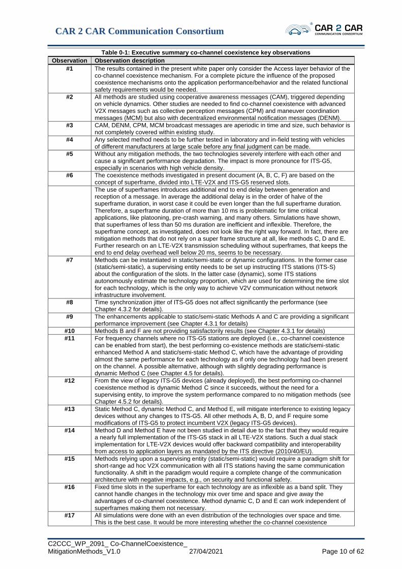
Table 0-1: Executive summary co-channel coexistence key observations
Observation Observation description
#1 The results contained in the present white paper only consider the Access layer behavior of the co-channel coexistence mechanism. For a complete picture the influence of the proposed coexistence mechanisms onto the application performance/behavior and the related functional safety requirements would be needed.
#2 All methods are studied using cooperative awareness messages (CAM), triggered depending on vehicle dynamics. Other studies are needed to find co-channel coexistence with advanced V2X messages such as collective perception messages (CPM) and maneuver coordination messages (MCM) but also with decentralized environmental notification messages (DENM).
#3 CAM, DENM, CPM, MCM broadcast messages are aperiodic in time and size, such behavior is not completely covered within existing study.
#4 Any selected method needs to be further tested in laboratory and in-field testing with vehicles of different manufacturers at large scale before any final judgment can be made.
#5 Without any mitigation methods, the two technologies severely interfere with each other and cause a significant performance degradation. The impact is more pronounce for ITS-G5, especially in scenarios with high vehicle density.
#6 The coexistence methods investigated in present document (A, B, C, F) are based on the concept of superframe, divided into LTE-V2X and ITS-G5 reserved slots.
The use of superframes introduces additional end to end delay between generation and reception of a message. In average the additional delay is in the order of halve of the superframe duration, in worst case it could be even longer than the full superframe duration. Therefore, a superframe duration of more than 10 ms is problematic for time critical applications, like platooning, pre-crash warning, and many others. Simulations have shown, that superframes of less than 50 ms duration are inefficient and inflexible. Therefore, the superframe concept, as investigated, does not look like the right way forward. In fact, there are mitigation methods that do not rely on a super frame structure at all, like methods C, D and E. Further research on an LTE-V2X transmission scheduling without superframes, that keeps the end to end delay overhead well below 20 ms, seems to be necessary.
#7 Methods can be instantiated in static/semi-static or dynamic configurations. In the former case (static/semi-static), a supervising entity needs to be set up instructing ITS stations (ITS-S) about the configuration of the slots. In the latter case (dynamic), some ITS stations autonomously estimate the technology proportion, which are used for determining the time slot for each technology, which is the only way to achieve V2V communication without network infrastructure involvement.
#8 Time synchronization jitter of ITS-G5 does not affect significantly the performance (see Chapter 4.3.2 for details).
#9 The enhancements applicable to static/semi-static Methods A and C are providing a significant performance improvement (see Chapter 4.3.1 for details)
#10 Methods B and F are not providing satisfactorily results (see Chapter 4.3.1 for details)
#11 For frequency channels where no ITS-G5 stations are deployed (i.e., co-channel coexistence can be enabled from start), the best performing co-existence methods are static/semi-static enhanced Method A and static/semi-static Method C, which have the advantage of providing almost the same performance for each technology as if only one technology had been present on the channel. A possible alternative, although with slightly degrading performance is dynamic Method C (see Chapter 4.5 for details).
#12 From the view of legacy ITS-G5 devices (already deployed), the best performing co-channel coexistence method is dynamic Method C since it succeeds, without the need for a supervising entity, to improve the system performance compared to no mitigation methods (see Chapter 4.5.2 for details).
#13 Static Method C, dynamic Method C, and Method E, will mitigate interference to existing legacy devices without any changes to ITS-G5. All other methods A, B, D, and F require some modifications of ITS-G5 to protect incumbent V2X (legacy ITS-G5 devices).
#14 Method D and Method E have not been studied in detail due to the fact that they would require a nearly full implementation of the ITS-G5 stack in all LTE-V2X stations. Such a dual stack implementation for LTE-V2X devices would offer backward compatibility and interoperability from access to application layers as mandated by the ITS directive (2010/40/EU).
#15 Methods relying upon a supervising entity (static/semi-static) would require a paradigm shift for short-range ad hoc V2X communication with all ITS stations having the same communication functionality. A shift in the paradigm would require a complete change of the communication architecture with negative impacts, e.g., on security and functional safety.
#16 Fixed time slots in the superframe for each technology are as inflexible as a band split. They cannot handle changes in the technology mix over time and space and give away the advantages of co-channel coexistence. Method dynamic C, D and E can work independent of superframes making them not necessary.
#17 All simulations were done with an even distribution of the technologies over space and time. This is the best case. It would be more interesting whether the co-channel coexistence

CAR 2 CAR Communication Consortium
C2CCC_WP_2091_ Co-ChannelCoexistence_ MitigationMethods_V1.0 27/04/2021 Page 11 of 62
methods are still working when the technologies are not evenly distributed, e.g., when two clusters of different technologies meet each other. It is expected that this is an issue for, e.g., semi-static superframe configurations.
#18 All mitigation Methods A-F allow backward compatibility of ITS-G5 with legacy ITS-G5 stations (already deployed).
#19 Based on the simulation results provided in this white paper and the considerations related to the Method D and Method E, only dynamic Method C can be considered as a viable potential solution for a co-channel coexistence mechanism in the future.
Providing an outlook for future technologies, it can be assumed that ITS-G5 based on IEEE
802.11bd will have the same coexistence behaviour as ITS-G5 based on IEEE 802.11p since they
both apply the same channel access mechanism (i.e., CSMA/CA) and the physical layers are
interoperable. 5G-NR V2X and LTE-V2X share also the same channel access mechanism based
on a synchronous network with semi-persistent scheduling (SPS) and reservations, however, they
differ on the physical layer (NR stands for new radio). Therefore, the overall problem statement
for co-channel coexistence of ITS-G5 based on IEEE 802.11bd and 5G NR V2X can be assumed
to be very similar to the co-channel coexistence of LTE-V2X and ITS-G5, most likely leading to
similar results. However, it has to be remarked that unlike IEEE 802.11p and IEEE 802.11bd
systems which can operate safely in the same channel, 5G-NR cannot be operated in the same
channel as LTE-V2X due to different radios and thus, additional investigation will be required to
guarantee a smooth sharing between 5G-NR, LTE-V2X and the different versions of ITS-G5 based
on IEEE 802.11p and IEEE 802.11bd.

CAR 2 CAR Communication Consortium
C2CCC_WP_2091_ Co-ChannelCoexistence_ MitigationMethods_V1.0 27/04/2021 Page 12 of 62
1 Introduction
1.1 Abstract
Today, two technologies are proposed as solutions for direct communications among vehicles and
roadside units, also called vehicle-to-everything (V2X) communications, in the 5.9 GHz bands. In
this document, these technologies are referred to as ITS-G5 [ETSI302663] and LTE-V2X
[ETSI303613].
ETSI has been tasked to perform studies on the possibilities to share the 5.9 GHz band on equal
terms between ITS-G5 and LTE-V2X. Two studies have been launched:
- TR 103 667 focusing on sharing spectrum;
- TR 103 766 focusing on co-channel coexistence methods, i.e., both technologies use the
same frequency channel in the same geographical area.
Scope of this document is to investigate the impact of reciprocal interference between ITS-G5 and
LTE-V2X cooperative-intelligent transport system-stations (C-ITS-Ss), when the two
technologies are concurrently used in the same channel, and the effectiveness of the mitigation
methods proposed in ETSI TR 103 766 [ETSI103766] to reduce the performance degradation (also
referred to as methods in the rest of the document for simplicity).
From ETSI perspective, if at least one coexistence method is providing sufficient indication that
co-channel coexistence can be realized, a next step may be to refine the best candidate method
by means of a subsequent TS or EN, which would in turn become an addendum on top of IEEE
and/or 3GPP specifications, applicable for deployment in Europe. Modifying the existing IEEE
or 3GPP specifications is probably not envisioned as such, although results of the co-channel co-
existence study may be taken into account for the drafting of future specifications at IEEE and/or
3GPP and/or ETSI.
ITS-G5 is a solution based on IEEE 802.11p at the physical and MAC layers. The channel access
mechanism is carrier sensing multiple access with collision avoidance (CSMA/CA). An ITS-G5
station transmits only when the channel is sensed as not used (idle) by other stations. If the channel
is known or sensed busy, the transmission is deferred to the end of the current transmission, plus
a backoff time with random duration, to avoid collisions at receivers. A transmission occupies the
entire channel. The sensing and backoff procedures are exemplified in Fig. 1-1, where one
reference station is assumed to initially find the channel busy and thus, defer its access to the
channel. More details of the channel access procedure can be found in ETSI EN 302 663
[ETSI302663].
Fig. 1-1: Illustration of access to medium by ITS-G5
time
freq
uen
cy
Other usersITS-G5 transmission
channel is
sensed busy
channel is
sensed idle

CAR 2 CAR Communication Consortium
C2CCC_WP_2091_ Co-ChannelCoexistence_ MitigationMethods_V1.0 27/04/2021 Page 13 of 62
Throughout this document, LTE-V2X denotes the sidelink LTE-V2X release 14 mode 4, which is
an LTE based technology introduced by 3GPP to allow vehicles and roadside units to communicate
directly without the need for the cellular infrastructure (i.e., base stations). Specifically, the term
sidelink specifies the direct PC5 communication and mode 4 implies that the resources to be used
are directly selected by each C-ITS-S in a fully distributed way. LTE-V2X is based at the lower
layers on single-carrier frequency division multiple access (SC-FDMA), which is a multi-carrier
access scheme assuming synchronization among the C-ITS-Ss and orthogonal resources in
principle. In LTE-V2X, the resources to be used are selected by each LTE-V2X station
independently, adopting a procedure known as sensing-based semi-persistent scheduling (SB-
SPS). Differently from ITS-G5, LTE-V2X is based on a synchronous network with usage of
reservations for messages sent at periodic time intervals. Thus, an LTE-V2X station with a packet
to transmit performs the resource selection based on an estimation of the future use by the other
stations, which in turn follows the information collected in the last 1 s. Such information includes
both measurements and received control messages. Once selected, the resource is used,
independently on what occurring in the channel. The allocation of the selected resource is
periodical, and it is performed for a certain time, which has a variable duration depending on a
specific algorithm and a number of parameters. In LTE-V2X, the transmissions might occupy only
a portion of the channel. The procedure is exemplified in Fig. 1-2, where one LTE-V2X stations
is assumed to select a resource, which occupies 3/5 of the channel. The same resource is used after
a given period, and then the allocation is modified.
Fig. 1-2: Illustration of access to medium from a C-ITS-S for LTE-V2X
When the two technologies are used in the same geographical region and in the same frequency
channel, a degradation in the performance of both technologies is expected due to the different
access mechanisms. This phenomenon is confirmed by the simulation results shown in Fig. 1-3,4
which provides the range, defined as the maximum distance to have a packet reception ratio (PRR)
higher than 90% varying the scenarios and technologies distribution. More specifically, per each
of the four considered scenarios, a given density of vehicles is assumed with variable percentage
of them equipped with either ITS-G5 or LTE-V2X. The two subfigures refer to the performance
of ITS-G5 C-ITS-Ss (left subfigure) and LTE-V2X C-ITS-Ss (right one). The various colors
correspond to the performance of the given technology for different percentage of C-ITS-Ss
equipped with that technology (the remaining C-ITS-Ss are equipped with the other one). The
range shown in the y-axis is normalized with respect to the maximum value for each technology,
i.e., the case in the low density scenario with 100% C-ITS-Ss equipped with that technology.5
4 Details on the simulation platform, scenarios, and metrics will be provided in the next Chapters. The results shown
in Fig. 1-3 are extrapolated from the curves shown in Chapter 4.2. 5 The normalization is performed in order to focus on the performance degradation in the presence of the co-channel
coexistence, rather than on a comparison of the two technologies.
time
freq
uen
cy
Other usersLTE-V2X transmission
Sensing Procedure (1s)
resources
allocated
allocation expired
possible new allocation

CAR 2 CAR Communication Consortium
C2CCC_WP_2091_ Co-ChannelCoexistence_ MitigationMethods_V1.0 27/04/2021 Page 14 of 62
Fig. 1-3: Maximum range with PRR at 90% for ITS-G5 (left) and LTE-V2X (right) for different levels of density and percentage of ITS-G5 and LTE-V2X C-ITS-Ss. The range is normalized to the maximum value obtained with each technology, i.e., corresponding to the low density scenario with a single technology.
As observable from Fig. 1-3, there is some degradation in both technologies when part of the C-
ITS-Ss uses the other one. As it might have been expected, given the sense-before-transmitting
mechanism of ITS-G5, the impact is heavier for ITS-G5 than for LTE-V2X. This consideration is
even more true looking at the denser scenarios, where the degradation of LTE-V2X is limited,
whereas the one of ITS-G5 is remarkable.
As witnessed by these example results, the degradation without specific countermeasures is
relevant. For this reason, a number of so-called co-channel coexistence methods are proposed in
ETSI TR 103 766 [ETSI103766], which all imply some modifications compared to current
specifications. The rest of the document will focus on the main advantages and drawbacks of each
method, along with its performance obtained through simulations in various scenarios.
The scope of this document is to provide an overview of the various co-channel co-existence
methods that are proposed and to show the performance that might derive from their adoption.
Note that the current document and the simulation environment are aimed at comparing the
performance degradation rather than the technologies to each other. Results are obtained given a
reasonable yet not necessarily best configuration for each of them. Details on the simulation
parameters are provided in Chapter 3.
1.2 Survey of document
The rest of the document is organized in three main Chapters. Chapter 2 describes the proposed
methods and the main implications from a standardization point of view. Chapter 3 details the
simulation environment and settings used for the evaluation of the methods. Finally, Chapter 4
reports numerical results with the aim to shed light on the impact expected by the implementation
of the various methods. The document is concluded with summary considerations in Chapter 5.

CAR 2 CAR Communication Consortium
C2CCC_WP_2091_ Co-ChannelCoexistence_ MitigationMethods_V1.0 27/04/2021 Page 15 of 62
2 The proposed mitigation methods
2.1 Introduction
In this Chapter, the mitigation methods that have been proposed in TR 103 766 [ETSI103766] are
recalled, which are named with capital letters from A to F, i.e., method A, method B, method C,
method D, method E, and method F. Some preliminary common concepts are discussed in Chapter
2.2, before entering in the detail of the various solutions in Chapter 2.3. A summary comparison,
before investigating their performance, is finally provided in Chapter 2.4.
2.2 Preliminary considerations on the coexistence methods
As already remarked, ITS-G5 is based on CSMA/CA. A C-ITS-S with a frame to transmit first
senses the channel and then proceeds only if it is sensed idle. A signal from an LTE-V2X C-ITS-
S, if received with a sufficiently high strength, can thus trigger the sensing procedure to detect the
channel as busy. It is to note that in ITS-G5 the channel is sensed busy when the received power
is above -85 dBm if the signal is recognized, whereas it needs to be above -65 dBm in the other
cases; this implies that the reception of an LTE-V2X signal implies the channel sensed as busy
only if it is above -65 dBm.
Differently, in LTE-V2X resources are reserved in advance, based on measurements performed in
a past time window of 1 s, and no sensing is performed when the transmission is about to start.
Thus, an LTE-V2X C-ITS-S cannot in general detect ITS-G5 signals and cannot differ the
transmissions to avoid collisions.
The reciprocal avoidance in the methods proposed in TR 103 766 [ETSI103766] is based on three
possible approaches:
• The first approach is to always send an ITS-G5 frame first, possibly used to reserve a
consequent time interval for LTE-V2X transmissions, as in methods D and E.
• The second approach is to somehow create separate time slots for the two technologies,
organized in what are called superframes, as in methods A, B, static C, and F. It can be
noted that, since ITS-G5 transmissions always occupy the entire channel bandwidth, a
separation in the frequency domain (sub channels) is not possible.
• The third approach is to add an ITS-G5 header in front of each LTE-V2X frame to reserve
the channel for the duration of the LTE-V2X frame, as in methods C and E.
The first approach (used by methods D and E), i.e., using ITS-G5 frames to announce the use of
the channel, requires the implementation of the full ITS-G5 stack also in LTE-V2X C-ITS-Ss. In
method D, a new type of ITS-G5 message is introduced to allow for LTE-V2X reservations, which
is not compatible with legacy ITS-G5 C-ITS-Ss. In method E an ITS-G5 header in front of each
LTE-V2X frame is added to mitigate interference to legacy ITS-G5 C-ITS-Ss. As a minor note,
the use of ITS-G5 messages does not exclude the use of superframes, which can be added to restrict
the use of the channel by either technology.
With the aim to focus on those methods that allow different C-ITS-Ss to only implement one of
the two technologies, this first approach is not considered for numerical results, and simulations
are performed only for the other approach (i.e., only for methods A, B, C, F).
The second approach, i.e., the one based on superframes, is further elaborated in the following
subchapter.

CAR 2 CAR Communication Consortium
C2CCC_WP_2091_ Co-ChannelCoexistence_ MitigationMethods_V1.0 27/04/2021 Page 16 of 62
2.2.1 Superframe and slots All the methods addressing the second approach (A, B, C, F), i.e., those that introduce a separation
of time into intervals used by either of the two technologies, are based on the concepts of
superframe and slots.
The superframe is a time interval of a given and constant duration, divided into two parts named
LTE-V2X time slot and ITS-G5 time slot. The superframe and time slots are exemplified in Fig. 2-
1. The LTE-V2X and ITS-G5 time slots can be of a given duration, indicated by a supervising
entity or dynamically determined by each C-ITS-S in a distributed way, depending on the specific
method and variant of the method. When the supervising entity is required, it can be needed either
for both technologies (normally in A) or for LTE-V2X only (normally in B, C, F).
In some cases, only LTE-V2X C-ITS-Ss need to be aware of the superframe and slots (normally
in B, C, F). In those cases, the ITS-G5 C-ITS-Ss somehow implicitly adhere to the structure as
better detailed in the further. In the other cases (normally in method A), both technologies must be
aware of the superframe structure and adhere to it; this directly implies the need for a certain level
of synchronization also in ITS-G5, which is not required otherwise.
Fig. 2-1: Example of superframe structure
2.2.1.1 Considerations on the implementation of superframes The organization of time into slots is of easy implementation for LTE-V2X, as long as the slot
duration is a multiple of 1 ms. LTE-V2X, in fact, is based on synchronous transmissions with an
allocation granularity in the time domain equal to the subframe, which lasts 1 ms. The LTE-V2X
standard already supports that LTE-V2X C-ITS-S can be configured to use only a portion of the
available subframes, which feature can be directly applied to prohibit the transmissions during the
ITS-G5 slot.
It is relevant to specify that restrictions have also been highlighted on the superframe and slots
duration. Specifically, given details of the options for time intervals in LTE-V2X mode 4, the
superframe needs to be of either 10, 25, or 50 ms (refer to TR 103 766 [ETSI103766] for further
details). In addition, ITS-G5 air-time transmissions can last up to slightly more than 4 ms and thus
5 ms is indicated as the minimum slot duration. For the numerical simulations carried in this study,
the same minimum duration is assumed also for LTE-V2X. This means that the following
configurations are possible:
• Superframe of 10 ms, with LTE-V2X slot and ITS-G5 slot fixed to 5 ms each.
• Superframe of 25 ms, with LTE-V2X slot and ITS-G5 slot of minimum 5 ms each.
• Superframe of 50 ms, with LTE-V2X slot and ITS-G5 slot of minimum 5 ms each.
time
freq
uen
cy
Technology A time slotTechnology B time slot
TATB
TSF Superframe

CAR 2 CAR Communication Consortium
C2CCC_WP_2091_ Co-ChannelCoexistence_ MitigationMethods_V1.0 27/04/2021 Page 17 of 62
2.2.2 Static, semi-static, dynamic configuration of the superframe When the superframe structure is foreseen, the proportion of LTE-V2X to ITS-G5 slot length
should be directly related to the proportion between C-ITS-Ss equipped with either technology. A
longer LTE-V2X slots should be adopted if the majority of C-ITS-Ss are equipped with LTE-V2X,
whereas a longer ITS-G5 slot should be used in the opposite case.
Noting that the proportion of vehicles equipped with the two technologies could vary in space and
time, the superframe structure can be configured in different ways:
• Static configuration: the slots are defined by regulators, once or very rarely, and provided
to all C-ITS-Ss offline from their initial operations; this solution is simple to implement
but requires agreements at the regulatory level and might be inefficient as unable to adapt
to the different conditions. An exemplification of the static configuration is provided in
Fig. 2-2.
• Semi-static configuration: the slots are defined by a supervising entity, which informs the
C-ITS-Ss on a regional basis with possible updates during time; this solution can better
cope with non-uniform and variable conditions but need a supervising entity and the
connection between the supervising entity and the C-ITS-Ss. An exemplification of the
semi-static configuration is provided in Fig. 2-3.
• Dynamic configuration: the slots are dynamically defined by the C-ITS-Ss based on some
local measurements; in this case, the current and local conditions are taken into account
and no supervising entity is required, although it might happen, in principle, that a different
allocation is used by different C-ITS-Ss in the same area. An exemplification of the
dynamic configuration is provided in Fig. 2-4.
The semi-static and dynamic configurations are expected to better adapt to the conditions of traffic
and technology penetration, which can vary during the day and regions.
As a drawback, the use of semi-static configuration requires a supervising entity that informs
(some of) the C-ITS-Ss of the structure to be used, which is an additional component to be defined
and optimized. Additionally, semi-static also implies that connectivity to an infrastructure is
necessary, at least for large part of the time, with specific messages defined for the communication
between the supervising entity and the C-ITS-Ss.
The dynamic configuration, on its own, requires additional and optimized mechanisms to correctly
estimate the technology proportions and might imply non-uniform conditions in some situations.
Fig. 2-2: Static superframe configuration
time
freq
uen
cy
TA
TB
Regulator-based
configuration
C-ITS-S 1
C-ITS-S 2

CAR 2 CAR Communication Consortium
C2CCC_WP_2091_ Co-ChannelCoexistence_ MitigationMethods_V1.0 27/04/2021 Page 18 of 62
Fig. 2-3: Semi-static superframe configuration
Fig. 2-4: Dynamic superframe configuration
2.2.3 Definition of the time slot boundaries in the dynamic configuration In the dynamic configuration, LTE-V2X C-ITS-Ss are requested to calculate the so-called
technology percentage 𝑇𝑝𝑒𝑟, which is a metric estimating the portion of LTE-V2X C-ITS-Ss over
all C-ITS-Ss (equipped with either LTE-V2X or ITS-G5). Based on such metric, they can
autonomously derive the LTE-V2X time slot duration. Different mechanisms are then introduced
by the various methods to allow ITS-G5 somehow infer the ITS-G5 time slot.
In particular, each LTE-V2X C-ITS-S senses the medium using a time window of a given duration
and performs the following calculation
𝑇𝑝𝑒𝑟 =𝐶𝐵𝑅𝐿𝑇𝐸
𝐶𝐵𝑅𝐿𝑇𝐸+𝐼𝑇𝑆𝐺5,
where 𝐶𝐵𝑅𝐿𝑇𝐸 is the channel busy ratio (CBR) that is estimated to be related to the LTE-V2X
transmissions only and 𝐶𝐵𝑅𝐿𝑇𝐸+𝐼𝑇𝑆𝐺5 is the CBR that is estimated to be related to both LTE-V2X
and ITS-G5 transmissions. The calculations of the two CBR parameters, detailed in TR 103 766
[ETSI103766], are recalled in annex A.
Once the 𝑇𝑝𝑒𝑟 is calculated, it is used to set the duration of the LTE-V2X time slot, according to
the equation reported in annex A. The principle is that the duration of the LTE-V2X time slot is
proportional to the portion of C-ITS-Ss that are estimated equipped with the LTE-V2X technology.
2.2.4 The LTE “last symbol gap” issue In LTE-V2X, each transmission lasts for one subframe in the time domain and one or more
subchannels in the frequency domain. Looking, in particular, at the time domain, the signal is not
transmitted in the 14th OFDM symbol of the 1ms subframe, which corresponds to approximately
71 µs. This gap is primarily used to allow the transceiver to change from transmitting to receiving
mode if needed.
Without any countermeasure, from the ITS-G5 perspective the silent part at the end of the
subframe implies that the channel is again available. It might however happen that also the
following subframe is used by an LTE-V2X C-ITS-S station. In most cases, such as if the ITS-G5
message adopt the settings normally used for CAM messages, the minimum backoff time before
time
freq
uen
cySupervisor-based
configuration
C-ITS-S 1
C-ITS-S 2
Supervisor-based
configuration
time
freq
uen
cy
Measurement-based
configuration for C-ITS-S 2
C-ITS-S 1
C-ITS-S 2
Measurement-based
configuration for C-ITS-S 2
Measurement-based
configuration for C-ITS-S 1
Measurement-based
configuration for C-ITS-S 1

CAR 2 CAR Communication Consortium
C2CCC_WP_2091_ Co-ChannelCoexistence_ MitigationMethods_V1.0 27/04/2021 Page 19 of 62
the transmission can start is longer than the gap, and thus a new LTE-V2X transmission starts
before the ITS-G5 C-ITS-S accesses the channel. However, there are cases when the backoff can
last less than the gap, causing the ITS-G5 transmission starting and eventually colliding with the
LTE signal using the following subframe. This situation, in particular, might occur with DENM
and high priority DENM in their usual settings.
The various mitigation methods provide different solutions to mitigate this issue, also known as
the “last symbol gap” problem.
2.3 Mitigation methods
A more detailed description of the mitigation methods is provided in this Chapter. Even if only
methods A, B, C, and F are evaluated through simulations in this document, a brief description is
also provided for methods D and E for the sake of completeness.
2.3.1 Mitigation method A The mitigation method A is based on an organization of the time axis in superframes of a given
duration, each of them consisting of a portion exclusively dedicated to LTE-V2X (the LTE-V2X
slot) and the remaining portion exclusively dedicated to ITS-G5 (the ITS-G5 slot). Guard intervals
can be used to separate the slots.
All C-ITS-Ss know and adhere to the organization, which also implies that all C-ITS-Ss need to
be synchronized in time with a certain accuracy (this aspect is later further elaborated). Each C-
ITS-S, equipped with either technology, is allowed to start a transmission only in the correspondent
slot, adopting the protocols currently defined without any modification.
The configuration is normally either static, which presumably implies some inefficiencies due to
the inability to adapt to variable proportion of ITS-G5 to LTE-V2X equipped C-ITS-Ss, or semi-
static. If the semi-static configuration is used, a supervising entity must be implemented, and the
C-ITS-Ss must be connected to an infrastructure for the majority of time in order to be reached by
such entity. The methodology used by the supervising entity to make the decisions is still an open
point. Dynamic configurations are also stated possible in TR 103 766 [ETSI103766], although
their implementation for Method A is not specified and thus appear unclear. In fact, even assuming
that ITS-G5 C-ITS-Ss can infer the superframe structure by estimating LTE signals (which might
need further investigations), still the LTE-V2X C-ITS-Ss must adhere to a common slot length at
least locally, which is thus presumably received again from a supervising entity and thus not
different from the semi-static approach.
In the case of static and semi-static configuration, the ITS-G5 C-ITS-Ss can optionally derive the
superframe and slot boundaries by performing some measurements and detecting ITS-G5
transmissions and non-ITS-G5 transmissions, as better detailed in TR 103 766 [ETSI103766]. This
feature needs further investigations.

CAR 2 CAR Communication Consortium
C2CCC_WP_2091_ Co-ChannelCoexistence_ MitigationMethods_V1.0 27/04/2021 Page 20 of 62
Fig. 2-5: Illustration of a superframe with three ITS-G5 and three LTE-V2X C-ITS-Ss transmitting under Method A
2.3.1.1 ITS-G5 channel rush problem and enhanced method A A variant of method A, called enhanced method A to differentiate it from the basic method A, is
also proposed, which aims at solving the main drawback that follows in ITS-G5 from the rigid
separation of time into exclusive slots, hereafter called channel rush problem: if several ITS-G5
have packets waiting in the transmission queue at the end of the LTE slot, they sense the channel
empty at the same time and they all concurrently start the CSMA/CA backoff mechanism, with an
increased probability of collisions. The issue is exemplified in Fig. 2-6, where three ITS-G5 C-
ITS-Ss are supposed to have a new packet generated during the LTE-V2X slot.
Fig. 2-6: Example of channel rush problem occurrence under method A
In order to avoid the channel rush problem, the enhanced method A assumes that ITS-G5 C-ITS-
Ss introduce an artificial delay from the instant in which the packet is received at the MAC layer
and the instant when the sensing and backoff procedure is started. Such delay is proportional to
the time that remains to the end of the superframe and allows to almost uniformly distribute the
beginning of the sensing and backoff procedure within the ITS-G5 slot.
More specifically, the implementation of such artificial delay follows. When a new ITS-G5 packet
is generated, the interval ∆𝑥 is calculated with respect to a reference start corresponding to the
beginning of the LTE slot 𝑡𝑎, which lasts for a duration 𝑇𝑎, less a guard interval 𝑇𝑔. Specifically,
∆𝑥= 𝑡 − (𝑡𝑎 − 𝑇𝑔). The guard interval 𝑇𝑔 is used to avoid transmissions from ITS-G5 C-ITS-Ss
that exceed the ITS-G5 slot boundary and is calculated as the duration of the ITS-G5 packet to be
transmitted, including the preamble and the data part. Then, the packet transmission is delayed and
transmitted at a new time instant 𝑡𝑛𝑒𝑤, within the next ITS-G5 slot of duration 𝑇𝑏, which starts at
time 𝑡𝑏. Specifically, 𝑡𝑛𝑒𝑤 belongs to a time window starting at 𝑡𝑏 and of duration 𝑇𝐺5 = 𝑇𝑏 − 𝑇𝑔.
The new time instant 𝑡𝑛𝑒𝑤 is defined such that 𝑡𝑛𝑒𝑤 = 𝑡𝑏 + ∆𝑦, where
∆𝑦= ∆𝑥𝑇𝐺5
𝑇𝐴+𝑇𝐵 .
frequency
superframe
ITS-G5 time slot
LTE-V2X time slot
time
frequency
superframe
ITS-G5 slot
LTE-V2X slot
generation of
ITS-G5 packets
time

CAR 2 CAR Communication Consortium
C2CCC_WP_2091_ Co-ChannelCoexistence_ MitigationMethods_V1.0 27/04/2021 Page 21 of 62
An example is provided in Fig. 2-7, where four ITS-G5 C-ITS-Ss introduce an artificial delay
before the sensing and backoff procedures; three of them are assumed to generate a new packet
within the LTE-V2X slots, whereas the other one generates the new packet during the ITS-G5 slot.
Fig. 2-7: Example of the solution to the channel rush problem in enhanced method A
2.3.2 Mitigation method B The mitigation method B is also based on the superframe structure, this time known only by LTE-
V2X C-ITS-Ss. In addition, the use of so-called “energy signals” (ES) is assumed, which are
signals transmitted without any informative content by LTE-V2X C-ITS-Ss, in order to make the
channel sensed as busy by ITS-G5 C-ITS-Ss. This means that LTE-V2X C-ITS-Ss can only
transmit during the LTE-V2X slot, whereas ITS-G5 C-ITS-Ss are expected to automatically use
the remaining part.
In the case of method B, the clear channel assessment (CCA) threshold below which the ITS-G5
C-ITS-Ss sense the channel as busy is reduced from -65 dBm to -85 dBm. This is necessary to
allow a correct detection of the energy signals and is the only modification needed in ITS-G5 C-
ITS-Ss with respect to current specifications.
Three types of ES are defined:
1. Type 1: during subframes within the LTE-V2X slot which are not used by any LTE-V2X
station, in order to avoid ITS-G5 using them.
2. Type 2: before the beginning of the LTE-V2X slot, in order to avoid ITS-G5 transmissions
starting at the end of the ITS-G5 slot and cross the slot boundary.
3. Type 3: within the last OFDM symbol of each used subframe, with the aim to remove the
gap defined for transmission-reception switch and time-alignment, which might be
misinterpreted by ITS-G5 C-ITS-Ss as the end of the LTE-V2X slot (i.e., the last symbol
gap issue of Chapter 2.2.4).
The ES type 1 (empty subframes) is sent in each subframe of the LTE-V2X slot by those LTE-
V2X C-ITS-Ss that in that subframe do not transmit and sense the channel as idle.
The ES type 2 (before superframe beginning) is sent just before the beginning of each superframe
by all LTE-V2X C-ITS-Ss that sense the channel as idle during a given time interval preceding
the LTE slot. The ES type 3 (during the 14th OFDM symbol of a subframe) is sent at the end of
each subframe by those LTE-V2X C-ITS-Ss that transmitted a packet in that subframe.
The tuning of several parameters (e.g., the band and power to use for the transmission of the ESs,
the sensing threshold to trigger the ES type 1 and 2, and the duration of the guard interval for ES
type 2) is left in TR 103 766 [ETSI103766] for future studies.
An example of the ES sent by LTE-V2X C-ITS-Ss is provided in Fig. 2-8.
frequency
superframe
ITS-G5 slot
LTE-V2X slot
generation of
ITS-G5 packets
time
CAR 2 CAR Communication Consortium
C2CCC_WP_2091_ Co-ChannelCoexistence_ MitigationMethods_V1.0 27/04/2021 Page 22 of 62
Fig. 2-8 Example illustration of a superframe with three ITS-G5 and three LTE-V2X C-ITS-Ss transmitting under method B
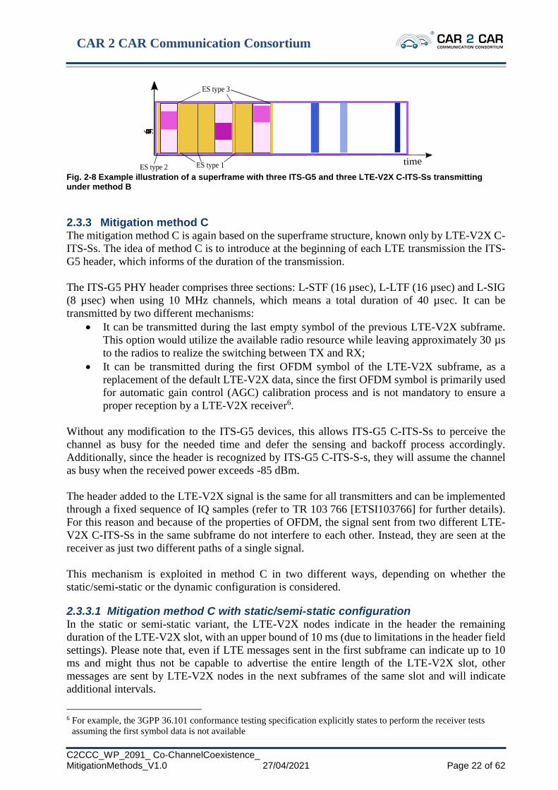
2.3.3 Mitigation method C The mitigation method C is again based on the superframe structure, known only by LTE-V2X C-
ITS-Ss. The idea of method C is to introduce at the beginning of each LTE transmission the ITS-
G5 header, which informs of the duration of the transmission.
The ITS-G5 PHY header comprises three sections: L-STF (16 µsec), L-LTF (16 µsec) and L-SIG
(8 µsec) when using 10 MHz channels, which means a total duration of 40 µsec. It can be
transmitted by two different mechanisms:
• It can be transmitted during the last empty symbol of the previous LTE-V2X subframe.
This option would utilize the available radio resource while leaving approximately 30 µs
to the radios to realize the switching between TX and RX;
• It can be transmitted during the first OFDM symbol of the LTE-V2X subframe, as a
replacement of the default LTE-V2X data, since the first OFDM symbol is primarily used
for automatic gain control (AGC) calibration process and is not mandatory to ensure a
proper reception by a LTE-V2X receiver6.
Without any modification to the ITS-G5 devices, this allows ITS-G5 C-ITS-Ss to perceive the
channel as busy for the needed time and defer the sensing and backoff process accordingly.
Additionally, since the header is recognized by ITS-G5 C-ITS-S-s, they will assume the channel
as busy when the received power exceeds -85 dBm.
The header added to the LTE-V2X signal is the same for all transmitters and can be implemented
through a fixed sequence of IQ samples (refer to TR 103 766 [ETSI103766] for further details).
For this reason and because of the properties of OFDM, the signal sent from two different LTE-
V2X C-ITS-Ss in the same subframe do not interfere to each other. Instead, they are seen at the
receiver as just two different paths of a single signal.
This mechanism is exploited in method C in two different ways, depending on whether the
static/semi-static or the dynamic configuration is considered.
2.3.3.1 Mitigation method C with static/semi-static configuration In the static or semi-static variant, the LTE-V2X nodes indicate in the header the remaining
duration of the LTE-V2X slot, with an upper bound of 10 ms (due to limitations in the header field
settings). Please note that, even if LTE messages sent in the first subframe can indicate up to 10
ms and might thus not be capable to advertise the entire length of the LTE-V2X slot, other
messages are sent by LTE-V2X nodes in the next subframes of the same slot and will indicate
additional intervals.
6 For example, the 3GPP 36.101 conformance testing specification explicitly states to perform the receiver tests
assuming the first symbol data is not available
frequency
ES type 2 ES type 1
ES type 3
time

CAR 2 CAR Communication Consortium
C2CCC_WP_2091_ Co-ChannelCoexistence_ MitigationMethods_V1.0 27/04/2021 Page 23 of 62
Based on the information derived by the received headers, the ITS-G5 nodes will infer the
superframe structure and will access the channel during the ITS-G5 slot. In order to avoid the
channel rush problem, the same deferring procedure detailed in Chapter 2.3.1.1 is used.
The static/semi-static method C requires that the ITS-G5 nodes are aware of the superframe
structure and overall procedure, even if there is no need for a supervising entity in ITS-G5. The
impact of possible synchronization inaccuracies is investigated in Chapter 4.
2.3.3.2 Mitigation method C with dynamic configuration In the dynamic configuration, the header sent by LTE-V2X C-ITS-Ss always indicates 1 ms and
has two functions: first, it allows ITS-G5 to sense the channel as busy when the power of the
received signal exceeds -85 dBm (if the signal is not recognized, the CCA threshold is instead set
to -65 dBm); second, it prevents the last symbol gap issue detailed in Chapter 2.2.4.
For method C in the dynamic configuration, no ITS-G5 C-ITS-Ss modification is required to
mitigate interference to legacy ITS-G5 C-ITS-Ss.
An example of dynamic method C is provided in Fig. 2-9. In that case, two transmissions from
ITS-G5 C-ITS-Ss are performed during the LTE-V2X slot in unused subframes.
Fig. 2-9 Example illustration of a superframe with three ITS-G5 and three LTE-V2X C-ITS-Ss transmitting under method C
2.3.4 Mitigation method D The mitigation method D relies on the transmission of ITS-G5 frames also by LTE-V2X C-ITS-
Ss. Such messages do not contain data but are broadcasted to reserve resources and are received
by both ITS-G5 and LTE-V2X C-ITS-Ss. Each message, also called reservation message,
announces the time instant at which a single or multiple LTE-V2X transmissions will start,
together with their duration.
Even if no modifications are required in the access layer of ITS-G5, all nodes need to be able to
decode the reservation message in order to respect the reservation. This implies that method D
cannot mitigate interference to legacy ITS-G5 C-ITS-Ss.
In Fig. 2-10, an example of method D is shown, with three LTE-V2X C-ITS-Ss sending the
reservation message before using the needed subchannels of an upcoming subframe.
frequency
ITS-G5
preamble
time

CAR 2 CAR Communication Consortium
C2CCC_WP_2091_ Co-ChannelCoexistence_ MitigationMethods_V1.0 27/04/2021 Page 24 of 62
Fig. 2-10 Example illustration of a superframe with three ITS-G5 and three LTE-V2X C-ITS-Ss transmitting under method D
2.3.5 Mitigation method E The mitigation method E is a combination of methods C and D. In particular, a reservation message
is sent on the shared channel to announce the time and duration of the next transmission, as for
method D. In addition, an ITS-G5 preamble precedes the LTE-V2X transmission, as for method
C, in order to let also the legacy ITS-G5 C-ITS-Ss to be aware of the transmission. An example of
method E is provided in Fig. 2-11.
Fig. 2-11 Example illustration of a superframe with three ITS-G5 and three LTE-V2X C-ITS-Ss transmitting under method E
2.3.6 Mitigation method F In mitigation method F, a superframe with an LTE-V2X slot and ITS-G5 slot is again assumed.
The superframe structure is known only by the LTE-V2X C-ITS-Ss, which inform ITS-G5 C-ITS-
Ss through the use of Clear-To-Send-To-Self (CTS-To-Self) messages. Such messages are
specified in IEEE 802.11 to be used inside a context of Basic Service Set (BSS) to reserve the use
of the channel by a base station to avoid the hidden terminal problems between terminals that are
not in range of each other. Using these messages to enable coexistence needs changes in IEEE
802.11. And it would impose a security threat, since such a message can block ITS-G5
communication for up to 32 ms without the need of any security authenticator.
For mitigation method F, the receiving ITS-G5 C-ITS-S sets the network allocation vector (NAV)
according to the content of the CTS-To-Self and assumes the channel as busy independently from
the sensing output. The maximum duration indicated by the CTS-To-Self is 32 ms.Specifically, in
method F, at the beginning of the LTE-V2X slot, selected LTE-V2X C-ITS-Ss transmit the CTS-
To-Self indicating as reserved the length of the LTE-V2X slot. The C-ITS-Ss receiving the CTS-
To-Self will avoid accessing the channel during the LTE-V2X slot.
It is to remark that the CTS-To-Self sent by two different nodes is not exactly the same and thus
two LTE-V2X C-ITS-Ss transmitting the CTS-To-Self at the same time interfere to each other
(this is different from the case of the ITS-G5 header addition in method C).
For this reason, only selected LTE-V2X C-ITS-Ss transmit the CTS-To-Self. The specific
procedure to select those LTE-V2X C-ITS-Ss needs further investigation, with possible examples
provided in [ETSI103766].
frequency
reservation
message
timefrequency
reservation
message
ITS-G5
preamble
time

CAR 2 CAR Communication Consortium
C2CCC_WP_2091_ Co-ChannelCoexistence_ MitigationMethods_V1.0 27/04/2021 Page 25 of 62
It is to note that in method F, like in method A, the use of a dynamic approach is doubtful. In fact,
only a portion of the LTE-V2X C-ITS-Ss is going to advertise the duration of the LTE-V2X slot,
which requires that all LTE-V2X C-ITS-Ss assume the same structure, at least on a local basis.
An example of method F is provided in Fig. 2-12.
Fig. 2-12 Example illustration of a superframe with three ITS-G5 and three LTE-V2X C-ITS-Ss transmitting under method F
2.4 Summary of the mitigation methods
The main characteristics of the six proposed methods are summarized in Table 2-1.
For each method, the following aspects are considered:
• If the method assumes that the transmission starts always with an ITS-G5 message, which
means that also LTE-V2X devices needs to implement the full ITS-G5 stack (methods D,
E), or not (methods A, B, C, F).
• If the method is based on superframe and slots (methods A, B, C, F), or not (methods D,
E).
• If the superframe structure is known by both technologies (method A) or just one (methods
B, C, F).
• If static and semi-static configuration of the superframe is normally used (method A, F) or
only possible (method B, C).
• If dynamic configuration of the superframe is also explicitly possible (method B, C) or its
implementation needs clarifications (method A, F).
• If there is need for a supervising entity (mandatory in methods A and F, optionally possible
in methods B and C, not required in methods D and E), specifying if for one technology
(methods B, C, F) or both (normally in method A).
• The main modifications required by LTE-V2X C-ITS-Ss (modifications are required in all
methods except for method A).
• The main modifications required by ITS-G5 C-ITS-Ss (modifications are required in all
methods except for dynamic method C).
• The countermeasure introduced to the issue of the LTE “last symbol gap” (see Chapter
2.2.4 for a description of the issue).
• The backward compatibility with legacy ITS-G5 C-ITS-Ss, given that C-ITS-Ss and road-
side units equipped with this technology are already respectively on the market and
deployed
• Coexistence / Interference mitigation for legacy ITS-G5 C-ITS-Ss, given that C-ITS-Ss
and road-side units equipped with this technology are already respectively on the market
and deployed
• List which combinations of different methods are possible to outline possible mitigation
method enhancements in future. E.g. method C can be enhanced by a combination of C
with method D to method E.
Table 2-1: Summary of all co-channel coexistence methods
frequency
timeCTS-To-Self

CAR 2 CAR Communication Consortium
C2CCC_WP_2091_ Co-ChannelCoexistence_ MitigationMethods_V1.0 27/04/2021 Page 26 of 62
Features
Basic or
enhanced
Method A
Method B (Semi-)
static
Method C
Dynamic
Method
C
Method D Method E Method F
ITS-G5 stack
required
No No No No Yes Yes No
Superframe
and slots
Yes Yes Yes Yes No No Yes
Superframe
awareness
Both tech. LTE-V2X
only
LTE-V2X
only;
inferred in
ITS-G5
LTE-V2X
only
- - LTE-V2X
only
(Semi-)static
configuration
Main choice Possible Yes No - - Main choice
Dynamic
configuration
Needs
clarifications
Possible No Yes - - Needs
clarifications
Supervising
entity
Yes7 Possibly,
LTE-V2X
only
Possibly,
LTE-V2X
only
Possibly,
LTE-V2X
only
No No Possibly,
LTE-V2X
only
Main modif.
to LTE-V2X
None New
“energy”
signals
Insertion of
ITS-G5
header
Insertion
of ITS-G5
header
ITS-G5
stack
ITS-G5 stack
and insertion
of ITS-G5
header
Transmission
of ITS-G5
CTS-to-self
Main modif.
to ITS-G5
Synchr. and
superframe
management
Modified
CCA
threshold
Synchr.
Required;
reservation
duration has
to be
modified
None Reading of
reservation
messages
Reading of
reservation
message
Reading and
handling of
CTS-to-self
message
About LTE
“last symbol
gap”
Slots known
by ITS-G5
Energy
signal
Indication
in header
Indication
in header
Reservation
duration
Reservation
duration
Indication in
CTS-to-self
Compliancy
with legacy
ITS-G5 /
backward
compatibility
No No No No: Yes Yes No
Coexistense /
Protection of
existing
legacy
devices
No8 Not
completely9
Yes, with
protection
equal to
dynamic
method C10
Yes No11 Yes, with
protection
equal to
dynamic
method C 12
unclear,
presumably
not working
7 Even if method A has been designed for use of supervising entities in both technologies, in [ETSI103766] a
solution is proposed to allow implementing the supervising entity only in LTE-V2X. 8 Legacy ITS-G5 C-ITS-Ss are not aware of the superframe structure. They will act as there was no mitigation
methods. 9 Legacy ITS-G5 C-ITS-Ss have the CCA threshold set to -65 dBm for undecoded signals, instead of -85 dBm. 10 Legacy ITS-G5 C-ITS-Ss are not able to identify the superframe and synchronize to it. Still, they are able to read
the ITS-G5 header sent by the LTE-V2X C-ITS-Ss and differ their access to the channel accordingly. 11 Legacy ITS-G5 C-ITS-Ss can receive the reservation messages but are not able to interpret the content. 12 Coexistence with legacy ITS-G5 C-ITS-Ss is given by the header insertion equivalent to dynamic method C, for
new C-ITS devices coexistence is even better due to the additional use of method D.

CAR 2 CAR Communication Consortium
C2CCC_WP_2091_ Co-ChannelCoexistence_ MitigationMethods_V1.0 27/04/2021 Page 27 of 62
Features
Basic or
enhanced
Method A
Method B (Semi-)
static
Method C
Dynamic
Method
C
Method D Method E Method F
Can be
combined
with
following
coexistence
methods
none to some
extent with
method C
dynamic
method C,
method E
static
method C,
method E
can be
combined
with all
other
methods
static or
dynamic
method C,
can be
combined
with all other
methods

CAR 2 CAR Communication Consortium
C2CCC_WP_2091_ Co-ChannelCoexistence_ MitigationMethods_V1.0 27/04/2021 Page 28 of 62
3 Simulator and Settings
3.1 Introduction
Results in this document were obtained with the open source LTEV2Vsim [Baz19] simulator,
adopting a subversion based on 5.4.13 LTEV2Vsim is developed by the National Laboratory of
Wireless Communications (WILAB) of CNIT, CNR-IEIIT and University of Bologna.
In this Chapter, the main settings are listed and justified. Further details are provided in Chapter
0.
3.2 Summary of settings
The main settings adopted in the simulations are summarized in Table 3.1. All numerical values
are discussed, with references when applicable, in the following subChapters.
Parameter Setting
Road layout Highway with 3+3 or 6+6 lanes, 4 m width
Road length 2 km
Number of vehicles in the scenario
(density)
123, 245, 666, 1000
(61.5, 122.5, 333, 500 vehicles/km)
Average vehicle speed 140, 70, 60, 50 km/h
CAM size 350 bytes
CAM generation interval Following the rules in [ETSI3026372]
Carrier frequency 5.9 GHz
Bandwidth 10 MHz
Path-loss model Winner+, Model B114
Shadowing Log-normal, 3 dB variance, correlated with decorrelation
distance 25 m
Transmission power density (before antenna
gain)
13 dBm/MHz15
Antenna gain (both TX and RX) 3 dBi
Noise figure 6 dB
Main settings in ITS-G5 MCS 2 (QPSK, coding rate 0.5); PER=0.1 @ SINR=3.1 dB with
2 RX diversity antennas
Arbitration inter-frame space 110 us
Maximum contention window 15
Sensing threshold for unknown signals -65 dBm
13 LTEV2Vsim is freely available at https://github.com/alessandrobazzi/LTEV2Vsim. Currently, the latest version is
5.4. The subversion used for the white paper is available upon request. Modifications will be included in the next
release of the software. 14 Winner+ model yields high propagation path loss which is a pessimistic model for range but might be an
optimistic model for interference mitigation and co-channel coexistense. 15 Similar power spectral density is assumed for all ITS-G5 and LTE-V2X messages, which means that if an LTE-
V2X message does not utilize all subchannels, its transmit power is reduced accordingly. For example, an LTE-
V2X message sent over 3 subchannels out of 5 undergoes a power backoff by 3/5, i.e. 2.2 dB.

CAR 2 CAR Communication Consortium
C2CCC_WP_2091_ Co-ChannelCoexistence_ MitigationMethods_V1.0 27/04/2021 Page 29 of 62
Parameter Setting
Main settings in LTE-V2X MCS 7 (QPSK, coding rate ~0.5); PER=0.1 @ SINR=4.1dB with
2 RX diversity antennas
Subchannel size 10, adjacent configuration. 3 subchannels per
CAM of 350 bytes16.
Mode 4 with keep probability 0.5, minimum power level to sense
a resource as busy -110 dBm, selection window between 1 and
100 TTI. Minimum (parameter T1) and maximum (parameter T2)
allocation delay 0 and 100 ms.
Hybrid automatic repeat request (HARQ) feature disabled.
Output metrics (see Chapter 3.6) Packet reception ratio (PRR), calculated in steps of 10 m
End-to-end delay (EED), calculated within 300 m
Inter-packet gap (IPG), calculated within 300 m
Data Age (DA), calculated within 300 m
Wireless blind spot probability (WBSP), calculated within 300 m
Coexistence configuration, when applicable Superframe 25 ms
In (semi-)static config., slots are 9 ms LTE-V2X and 16 ms ITS-
G5 when technology proportion is 25% LTE-V2X-75% ITS-G5;
slots are 13 ms LTE-V2X and 12 ms ITS-G5 when technology
proportion is 50% LTE-V2X-50% ITS-G5; slots are 16 ms LTE-
V2X and 9 ms ITS-G5 when technology proportion is 75% LTE-
V2X-25% ITS-G5.
Table 3-1: Main simulation settings
3.3 Scenarios
The following highway scenarios are used in this document:
• Low density: 61.5 vehicles/km travelling at an average speed of 140 km/h in a 2 km 3+3
lanes highway segment; this scenario corresponds to scenario 2 in [ETSI103766].
• Medium density: 122.5 vehicles/km travelling at an average speed of 70 km/h in a 2 km
3+3 lanes highway segment; this scenario corresponds to scenario 3 in [ETSI103766].
• High density: 333 vehicles/km travelling at an average speed of 60 km/h in a 2 km 6+6
lanes highway segment; this scenario has the same density of scenario 5 in [ETSI103766].
• Congested: 500 vehicles/km travelling at an average speed of 50 km/h in a 2 km 6+6 lanes
highway segment; this scenario has the same density and average speed of scenario 6 in
[ETSI103766].
Vehicles are evenly distributed over the lanes, with initial position randomly dropped with uniform
distribution over the road length. Wrap-around is applied, meaning that when a vehicle exits the
scenario it enters the same lane from the opposite end of the road segment. Each vehicle moves at
a speed which is randomly selected from a Gaussian distribution, with a standard deviation equal
to one tenth of the average speed.
Through Fig. 3-1 and Fig. 3-2, insights are provided in the implications of the various scenarios.
In particular, in Fig. 3-1, the average speed and the average number of packets per second per
vehicle are shown varying the vehicle density. As observable and expected, the two metrics are
directly proportional to each other. In fact, as observed for example in [Mar18], the interval
between the generation of two consecutive packets is inversely proportional to the speed of the
vehicle.
16 It should be noted that the scheduling of a packet over 3 subchannels out of 5 does not mean that two subchannels
are left unutilized. The simulator is built as per 3GPP specifications and each station creates its own lists L1 and
L2 of candidate resources, based on its own measurements.
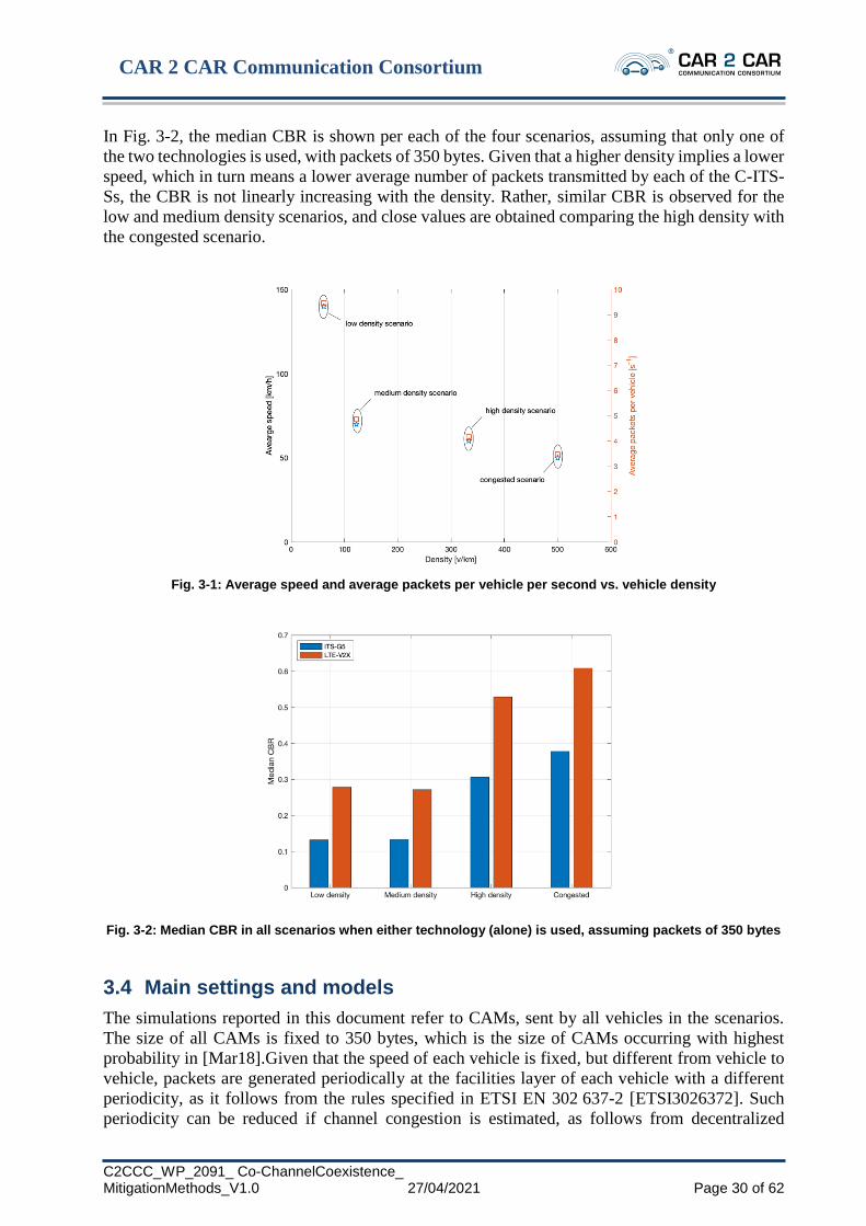
CAR 2 CAR Communication Consortium
C2CCC_WP_2091_ Co-ChannelCoexistence_ MitigationMethods_V1.0 27/04/2021 Page 30 of 62
In Fig. 3-2, the median CBR is shown per each of the four scenarios, assuming that only one of
the two technologies is used, with packets of 350 bytes. Given that a higher density implies a lower
speed, which in turn means a lower average number of packets transmitted by each of the C-ITS-
Ss, the CBR is not linearly increasing with the density. Rather, similar CBR is observed for the
low and medium density scenarios, and close values are obtained comparing the high density with
the congested scenario.
Fig. 3-1: Average speed and average packets per vehicle per second vs. vehicle density
Fig. 3-2: Median CBR in all scenarios when either technology (alone) is used, assuming packets of 350 bytes
3.4 Main settings and models
The simulations reported in this document refer to CAMs, sent by all vehicles in the scenarios.
The size of all CAMs is fixed to 350 bytes, which is the size of CAMs occurring with highest
probability in [Mar18].Given that the speed of each vehicle is fixed, but different from vehicle to
vehicle, packets are generated periodically at the facilities layer of each vehicle with a different
periodicity, as it follows from the rules specified in ETSI EN 302 637-2 [ETSI3026372]. Such
periodicity can be reduced if channel congestion is estimated, as follows from decentralized

CAR 2 CAR Communication Consortium
C2CCC_WP_2091_ Co-ChannelCoexistence_ MitigationMethods_V1.0 27/04/2021 Page 31 of 62
congestion control (DCC). More details on the implementation of DCC in the simulator are
provided in Annex B.
Other types of messages such as collective perception messages (CPM) and maneuver
coordination messages (MCM) but also decentralized environmental notification messages
(DENM) may lead to different simulation results as they yield different CSMA/CA parameters
(e.g. AIFS time) or packet sizes and might be subject to future study.
The carrier frequency is 5.9 GHz, and a channel of 10 MHz is assumed. All transceivers are half
duplex. All vehicles are assumed to transmit with the same power density of 13 dBm/MHz, and
with the same antenna gain, both for transmission and reception, 𝐺𝑎 = 3 dBi (as an average value
of MobileMark SMW314 [SMW314]). At the receiver, a noise figure 𝐹𝑛 = 6 dB is assumed (as
the NXP SAF5400 [SAF5400]).
Given the scenarios, the propagation is assumed as always in line-of-sight (LOS) conditions. In
compliance with [ETSI103766], the propagation is modeled using the pathloss proposed by the
Winner+, scenario B1, with correlated shadowing. The shadowing is log-normally distributed with
zero mean and a standard deviation of 3 dB, and is correlated with decorrelation distance 25 m.
How fast variations of the channel are reproduced is detailed later.
All C-ITS-Ss adopt the same modulation and coding scheme (MCS). In particular, following the
specifications, MCS 2 (quadrature phase-shift keying, QPSK, with code rate ½) is adopted in ITS-
G5. In order to have a similar modulation and coding scheme, MCS 7 is adopted in LTE-V2X;
each frame of 350 bytes uses QPSK with code rate approximately 0.6, and it occupies 3 of the 5
available subchannels that are mandated by the specifications in one 10 MHz channel
[ETSI303613].
Additionally, in ITS-G5 the arbitration interframe space (AIFS) is set to 110 us and the contention
window (CW) to 15.In LTE-V2X, the adjacent configuration is assumed for the transmission of
the SCI. Regarding the allocation period, 100 ms is used for all scenarios. Finally, in the mode 4
algorithm settings, the power threshold of initial identification of busy resources is set to -110 dBm
and the keep probability is set to 0.5 as intermediate value between 0 and 0.8.
During the simulation, the correctness of each transmission is defined starting from the calculation
of the average signal to interference and noise ratio (SINR), as detailed in annex B. Given a certain
SINR, the loss is probabilistically derived using curves of packet error rate (PER) vs. SINR,
obtained with link level simulations, which take into account also the impact of small-scale fading.
In particular, the curves reported in Fig. 3-3 are used, where PER is 0.1 when SINR is 3.1 dB in
the case of ITS-G5 and 4.1 dB in the case of LTE-V2X. These curves were obtained assuming 1
transmitting antenna and 2 receiving antennas with 1x2 IRC (Hermitian noise covariance Matrix)
equalizer, highway LOS fading model as per [ETSI1032571], channel estimate based on preamble
and feedback loop, perfect control channel decoding, perfect synchronization.

CAR 2 CAR Communication Consortium
C2CCC_WP_2091_ Co-ChannelCoexistence_ MitigationMethods_V1.0 27/04/2021 Page 32 of 62
Fig. 3-3: PER vs. SINR curves used in the simulations
3.5 Assumptions related to the methods
In this Chapter, the main assumptions and approximations adopted in the simulation of the
mitigation methods are discussed.
In all cases, unless otherwise specified, all nodes are assumed ideally synchronized. Discussing
how to obtain synchronization in LTE-V2X or ITS-G5 is outside the scope of the present
document. The impact of an error in the synchronization of ITS-G5 nodes, which is a technology
normally not requiring strict synchronization, is anyway investigated in when relevant.
In all cases, no guard interval is assumed between the slots (unless explicitly indicated by the
method, such as for example in enhanced method A).
In numerical results, the label “(semi-)static” is used with the aim to denote that it corresponds to
either static or semi-static.
3.5.1 Assumptions related to method A No relevant assumptions or approximations need to be indicated for method A.
3.5.2 Assumptions related to method B In method B, the following assumptions and approximations apply:
1. The transmission power density of Ess is set equal to the transmission power density of
data packets.
2. For the purpose of the ES type 1 (empty subframes) and type 2 (before superframe
beginning), the sensing threshold in LTE-V2X is set to the same value used by mode 4
(i.e., -94 dBm per subchannel).
3. The ES type 1 (empty subframes) lasts for the duration of the entire subframe; this
introduces an approximation, as in a real system an initial gap is needed to let C-ITS-Ss
check that no-one is transmitting; this approximation is expected to be negligible.
4. The duration of the ES type 2 (before the superframe beginning) is set to the duration of
an ITS-G5 packet of 350 bytes with MCS 2.
5. The ES type 3 (during the 14th OFDM symbol of a subframe) lasts for the duration of the
entire OFDM symbol, instead of just a portion of it; this approximation is expected to be
negligible.

CAR 2 CAR Communication Consortium
C2CCC_WP_2091_ Co-ChannelCoexistence_ MitigationMethods_V1.0 27/04/2021 Page 33 of 62
3.5.3 Assumptions related to method C
In method C, the following assumptions and approximations apply:
1. The ITS-G5 header added to the LTE-V2X signal is not explicitly simulated; this implies
that the LTE-V2X physical sidelink shared channel (PSSCH) decoding performance is
approximated as the same as without the header insertion; the impact of this approximation
is expected to be negligible.
2. The decoding of the ITS-G5 header sent by LTE-V2X stations is not explicitly simulated;
rather, at the beginning of each subframe, per each of the ITS-G5 station which are not yet
transmitting or receiving another signal, the power received from all the transmitting LTE-
V2X stations is summed (recalling that the header is the same for all LTE-V2X stations
and transmissions behave as multiple paths at the receiver) and the corresponding
instantaneous SINR is derived; the SINR includes noise and interference from possible
ITS-G5 stations that are transmitting at the beginning of the subframe; the header is then
assumed correctly received if the SINR is above the one corresponding to 90% PER of the
link layer curve of ITS-G5.17
3. In the static/semi-static configuration, the ITS-G5 C-ITS-Ss procedure to acquire the
superframe structure is assumed ideal; therefore, the performance of static/semi-static
method C is the same as the enhanced method A.
3.5.4 Assumptions related to method F
In method F, the following assumptions and approximations apply:
1. The CTS-to-Self is not explicitly simulated; this implies that the LTE-V2X data field is
approximated as the same as without the header insertion; the impact of this approximation
is expected to be limited.
2. The correct/erroneous fate of the CTS-to-Self is assessed based on the instantaneous SINR
and adopting the same link layer curve of ITS-G5.18 To be noted that the CTS-to-Self
messages sent by more than one LTE-V2X C-ITS-S are not identical and thus interfere to
each other.
3. The CTS-to-Self is sent by each LTE-V2X C-ITS-S that have a resource reserved in that
superframe, unless one of the other LTE-V2X C-ITS-Ss in the proximity is using either: i)
one of the resources of the preceding subframes of the same superframe or ii) a lower
frequency subchannel of the same subframe.
3.6 Output metrics
Results for the various cases and scenarios are obtained for the metrics that follow. For the sake
of conciseness, not all the figures are shown in the white paper and the interested reader can
download them from the GitHub page of the simulator.19
Specifically, results are obtained in terms of:
17 The adoption of the 90% PER for the SINR threshold takes into account the fact that the header is more protected
than a 350-byte packet adopting QPSK 1/2. 18 If the CTS-to-Self is sent using MCS 2 (QPSK ½), then the approximation is only in the length of the message
and its impact is expected to be very limited. 19 The link to the GitHub page of LTEV2Vsim is https://github.com/alessandrobazzi/LTEV2Vsim. Before the
publication of the white paper, the figures will be available at https://www.dropbox.com/s/f0yzd3iumsaivo6/WP-
Figures-Dec2020.zip.

CAR 2 CAR Communication Consortium
C2CCC_WP_2091_ Co-ChannelCoexistence_ MitigationMethods_V1.0 27/04/2021 Page 34 of 62
• PRR, which is computed as the average ratio between the number of C-ITS-Ss correctly
decoding a CAM at a certain distance from the transmitter and the overall number of C-
ITS-Ss at the same distance.
• End-to-end delay (EED), which is the time difference between the packet generation and
the packet reception, considering all the links within a maximum distance; processing time
is neglected.
• Inter-packet gap (IPG), which is the time difference between two consecutive CAMs
received by the same receiver from the same transmitter, considering all the links within a
maximum distance; the IPG implicitly informs about the correlation among errors.
• Data age (DA), which is the time difference between the instant when the last message
correctly received by a given receiver was generated and the instant a new message is
received by the same receiver from the same transmitter, considering all the links within a
maximum distance; the DA includes at the same time the transmission delay and the time
difference between consequent correctly decoded CAMs.
• Wireless Blind Spot Probability (WBSP), which is the probability that no CAMs are
received in an interval of a given duration (wireless blind spot duration) by a given receiver
from a given transmitter, considering all the links within a maximum distance [Baz20]; this
metric, which intuitively indicates the probability to have no information about a neighbor
within a given time interval, is the only one not indicated in [ETSI103766].
The PRR is obtained considering the transmitter-receiver distance with steps of 𝑑𝑠𝑡𝑒𝑝 = 10 m; in
other words, the PRR at 𝑑𝑠𝑡𝑒𝑝 ∙ Κ meters (where Κ is a positive integer) is calculated as the ratio
between all correct receptions by C-ITS-Ss within 𝑑𝑠𝑡𝑒𝑝 ∙ (Κ − 1) and 𝑑𝑠𝑡𝑒𝑝 ∙ Κ meters from the
source and all the C-ITS-Ss within the same distances from the source. PRR is shown varying the
distance.
The EED, IPG, DA, and WBSP are obtained considering all transmissions between C-ITS-Ss that
are within a maximum distance of 300 m from each other.
EED, IPG, and DA, are provided in terms of complementary cumulative distribution function
(ccdf) varying the value. In the case of WBSP, the probability is shown varying the duration of the
wireless blind spot.

CAR 2 CAR Communication Consortium
C2CCC_WP_2091_ Co-ChannelCoexistence_ MitigationMethods_V1.0 27/04/2021 Page 35 of 62
4 Results
4.1 Introduction
In this Chapter, simulation results are provided to assess the performance of the mitigation
methods. Baseline results, in the absence of mitigation methods are first shown in Chapter 4.2.
Then, the methods in static/semi-static configuration are investigated in Chapter 4.3 and in
dynamic configuration in Chapter 4.4. In Chapter 4.5, a comparison between the most relevant
cases deriving from the previous Chapters are compared. Finally, in Chapter 4.5 a summary is
provided.
4.2 Baseline Results
The results shown in this Chapter refer to the baseline case, where the legacy protocols are used
in both technologies and no mitigation method is used.
In particular, PRR vs. distance is shown through Fig. 4-1 to Fig. 4-4 in the four scenarios. In all
figures, the subfigure on the left refers to the performance of ITS-G5 and the subfigure on the right
refers to the performance of LTE-V2X. In all the cases, a portion of the vehicles is equipped with
ITS-G5 and the others are equipped with LTE-V2X.
As already anticipated in the introduction (see Chapter 1.1), the presence of the other technology
significantly impacts on the PRR. Even if ITS-G5 C-ITS-Ss perform sensing before transmitting,
they are not able to stop once the transmission has started and might thus collide with LTE-V2X
transmissions starting later. LTE-V2X C-ITS-Ss, on their own, do not sense the channel just before
transmitting and cannot estimate the ITS-G5 transmissions unless they are periodic with a
periodicity multiple of the allocation period (set here to 100 ms).
In general, the impact is worse for ITS-G5. For ITS-G5, the gap between the PRR obtained with
100% ITS-G5 C-ITS-Ss and that obtained in the presence of LTE-V2X C-ITS-Ss increases with
the density of the vehicles; at the same time, the difference between having 25% of C-ITS-Ss
equipped with LTE-V2X and 75% reduces. The motivation for this behavior is that with the
increased vehicle density the LTE-V2X nodes tend to occupy most of the channel and ITS-G5
nodes tend to differ most of their transmissions. By design, in fact, each LTE-V2X C-ITS-S always
transmits a packet within a given maximum time from when the packet is generated. Such
parameter is set here to its maximum, which is 100 ms.
From the LTE-V2X perspective, the presence of IEEE 802.11p causes a PRR reduction in lowly
loaded channel conditions. In denser scenarios, the impact of IEEE 802.11p becomes less relevant.
Indeed, in the congested scenario, the performance with LTE-V2X only or with any other
combination of the two technologies brings to similar PRR from the LTE-V2X C-ITS-S
perspective.
These results clearly remark the need for the definition of some mitigation methods if the two
technologies need to share the same channel.

CAR 2 CAR Communication Consortium
C2CCC_WP_2091_ Co-ChannelCoexistence_ MitigationMethods_V1.0 27/04/2021 Page 36 of 62
Fig. 4-1: Baseline, low density. PRR vs. distance
Fig. 4-2: Baseline, medium density. PRR vs. distance
Fig. 4-3: Baseline, high density. PRR vs. distance
Fig. 4-4: Baseline, congested. PRR vs. distance

CAR 2 CAR Communication Consortium
C2CCC_WP_2091_ Co-ChannelCoexistence_ MitigationMethods_V1.0 27/04/2021 Page 37 of 62
From Fig. 4-5 to Fig. 4-8, the other metrics are shown with focus on the high density scenario. As
observable, the outputs are in their essence similar to PRR. Looking at ITS-G5, the performance
worsens with the increase of the percentage of vehicles equipped with LTE-V2X. From the LTE-
V2X perspective, instead, the performance is rather similar.Since this tends to be true for all
scenarios, in most of the cases we will focus only on PRR in the reminder of the document.
Fig. 4-5: Baseline, high density. Ccdf of DA
Fig. 4-6: Baseline, high density. Ccdf of EED
Fig. 4-7: Baseline, high density. Ccdf of IPG

CAR 2 CAR Communication Consortium
C2CCC_WP_2091_ Co-ChannelCoexistence_ MitigationMethods_V1.0 27/04/2021 Page 38 of 62
Fig. 4-8: Baseline, high density. WBSP
4.3 Results with static configurations
In this Chapter, results are provided when the static or semi-static configurations are adopted.
Specifically, in Chapter 4.3.1, the various methods are compared assuming that the supervising
entity indicates the correct technology distribution to the C-ITS-Ss and that all nodes are perfectly
synchronized. What happens if a synchronization error is assumed in ITS-G5 is discussed in
Chapter 4.3.2, while the impact of an inaccurate indication of the technology distribution by the
supervising entity is addressed in Chapter 4.3.3.
4.3.1 Results with static and semi-static methods From Fig. 4-9 to Fig. 4-14, the various methods are compared in terms of PRR, for various
technology proportions and for both the medium and high density scenarios. In all plots, dashed
curves are shown as benchmarks, one indicating what happens if 100% C-ITS-Ss are of the given
technology (ITS-G5 in the left plot, LTE-V2X in the right plot) and the other what happens if no
mitigation method is used.
If we focus on method A from the ITS-G5 perspective, we see that the performance in general
improves at long distance but worsens at short distance. From the one side, in fact, the strict
separation into slots allows ITS-G5 not to be interfered by LTE-V2X transmissions, which is
especially beneficial at longer distances. From the other side, this method suffers of the channel
rush problem detailed in Chapter 2.3.1.1, which causes a higher collision probability at the
beginning of the ITS-G5 slot and involves also nodes in proximity to each other. The channel rush
problem causes a PRR worsening which is especially notable for short distances, where the benefit
of lower interference from LTE-V2X stations is less relevant. It can also be noted that the negative
impact of the channel rush problem is more evident when the LTE-V2X slot length is 50% or 75%
of the superframe, compared to the case where it is only 25% of the superframe.
From the LTE-V2X perspective, instead, method A shows always a clear improvement compared
to the case of no mitigation methods. In most cases, the improvement allows to reach the
benchmark curve of LTE-V2X alone. This means that giving to LTE-V2X a portion of the slots
proportional to the traffic allows LTE-V2X to perform similarly. The performance of method A
from the LTE-V2X perspective is only slightly worse in the case of 25% LTE-V2X to 75% ITS-
G5 distribution; this is due to the fact that in such case the LTE-V2X slot lasts for only 6 subframes,
with the first one possibly overlapped by an ITS-G5 transmission (in basic method A the limitation
is on the instant of transmission start and not on transmission end); more in detail, the transmissions
performed by ITS-G5 C-ITS-Ss at the end of the ITS-G5 slot create interference to LTE-V2X,
which also makes LTE-V2X C-ITS-Ss to consider the first subframe less suitable for selection in

CAR 2 CAR Communication Consortium
C2CCC_WP_2091_ Co-ChannelCoexistence_ MitigationMethods_V1.0 27/04/2021 Page 39 of 62
the SB-SPS process, thus slightly increasing the probability of collisions within the remaining 5
subframes.
If the enhanced method A is now observed, it is evident that it succeeds in both avoiding the
channel rush problem (ITS-G5 side) and letting LTE-V2X fully exploiting the LTE-V2X slot
(LTE-V2X side). Observing the various figures, in most of the cases the performance adopting the
enhanced method A is very close to the performance obtained with a single technology for both
ITS-G5 and LTE-V2X.
Given that the enhanced method A and the static/semi-static method C coincide except for the way
ITS-G5 C-ITS-Ss are aware of the superframe structure, the two have the same performance and
a single curve is shown in the plots. Thus, all the comments provided for the enhanced method A
apply also to the static/semi-static method C.
The remaining two methods, B and F, show overall worse performance than the others. Method
B, in particular, implies in most cases ITS-G5 PRR at short distances similar to basic method A,
which means that the overall effectiveness of method B to deny LTE-V2X C-ITS-Ss to access the
channel during the LTE-V2X slot brings also in this case to the channel rush problem. Differently
from method A, method B is not able to impede all transmissions from ITS-G5 C-ITS-Ss during
the LTE-V2X slot and those that are performed tend to collide with some LTE-V2X signal or ES.
From the LTE-V2X point of view the performance is slightly better or slightly worse than without
any method, depending to the case. With method B, LTE-V2X has access to only a portion of the
superframe, without guarantees of no interference from ITS-G5.
Referring to method F, PRR appears slightly better than basic Method A for ITS-G5 but worse for
LTE-V2X. The point with method F is that it relies on the CTS-to-Self that is sent at the beginning
of the superframe by some and not all the LTE-V2X C-ITS-Ss. Often, such message is not received
by the ITS-G5 C-ITS-Ss, which are thus not aware of the LTE-V2X slot. Given the possibility that
unaware ITS-G5 C-ITS-Ss interfere during all the superframe and that LTE-V2X C-ITS-Ss restrict
their access to the LTE-V2X slot, the result is a lower PRR in LTE-V2X compared to the other
methods, and even worse performance than the no methods case when the channel is highly loaded.
Fig. 4-9: Static with ideal slots, medium density, 75% ITS-G5. PRR vs. distance

CAR 2 CAR Communication Consortium
C2CCC_WP_2091_ Co-ChannelCoexistence_ MitigationMethods_V1.0 27/04/2021 Page 40 of 62
Fig. 4-10: Static with ideal slots, medium density, 50%-50%. PRR vs. distance
Fig. 4-11: Static with ideal slots, medium density, 75% LTE-V2X. PRR vs. distance
Fig. 4-12: Static with ideal slots, high density, 75% ITS-G5. PRR vs. distance
Fig. 4-13: Static with ideal slots, high density, 50%-50%. PRR vs. distance

CAR 2 CAR Communication Consortium
C2CCC_WP_2091_ Co-ChannelCoexistence_ MitigationMethods_V1.0 27/04/2021 Page 41 of 62
Fig. 4-14: Static with ideal slots, high density, 75% LTE-V2X. PRR vs. distance
4.3.2 Impact of synchronization The results shown in Chapter 4.3.1 assume perfect synchronization among all C-ITS-Ss. Whereas
it is an acceptable assumption for LTE-V2X C-ITS-Ss, as synchronization is needed for the correct
operations in that technology, the same assumption might not be realistic in ITS-G5.
In this Chapter, a synchronization error is thus assumed for the ITS-G5 C-ITS-Ss. Specifically,
each ITS-G5 C-ITS-S is affected by a constant timing error, which is uniformly randomly chosen
between -0.1 ms and +0.1 ms. Given the worse performance observed for methods B and F, results
are provided only for basic method A and for enhanced method A/(semi-)static method C.
Results are shown in Fig. 4-15 and Fig. 4-16 in terms of PRR vs. distance, focusing on 50%-50%
technology distribution for both medium and high density scenarios. As observable, the
synchronization error is not an issue. Maybe surprisingly, it even implies better performance in
basic method A; the synchronization error, in fact, impacts on the instant when an ITS-G5 C-ITS-
S considers the ITS-G5 slot to start, which is the instant at which it begins the backoff procedure;
as a consequence, the randomization due to the imperfect synchronization brings different ITS-G5
C-ITS-Ss to start the backoff at different times and thus to a reduction of the channel rush problem.
In the case of enhanced method A and static/semi-static method C, the channel rush problem is
not present and the randomization of the initial instant of the backoff does not bring to the same
advantage. Yet, the difference between ideally synchronized or not is negligible in this case.
Fig. 4-15: Static with ideal slots, medium density, 50%-50%, with ideal synchronization or with a uniformly distributed synchronization error of ITS-G5 C-ITS-Ss between -0.1 ms and +0.1 ms. PRR vs. distance

CAR 2 CAR Communication Consortium
C2CCC_WP_2091_ Co-ChannelCoexistence_ MitigationMethods_V1.0 27/04/2021 Page 42 of 62
Fig. 4-16: Static with ideal slots, high density, 50%-50%, with ideal synchronization or with a uniformly distributed synchronization error of ITS-G5 C-ITS-Ss between -0.1 ms and +0.1 ms. PRR vs. distance
4.3.3 Impact of erroneous technology proportion settings from the supervising entity
A second simplification in Chapter 4.3.1 is that the supervising entity is assumed to know the
correct technology proportion. Hereafter, the impact of this simplification is assessed, also in this
case limiting the focus to basic method A and enhanced method A/(semi-)static method C.
The impact of the inaccuracy is verified assuming that the real proportion is 5.55% more than the
one known by the supervising entity in either direction (i.e., either 5.55% more ITS-G5 C-ITS-Ss
or 5.55% more LTE-V2X C-ITS-Ss). The rational for this percentage, based on the use of binomial
distributions, is detailed in TR 103 766 [ETSI103766].
In Fig. 4-17 and Fig. 4-18, PRR vs. distance is shown for an advertised 50%-50% technology
distribution in the medium and high-density scenarios. In each plot, both the case where 55.55%
of C-ITS-Ss implement LTE-V2X (indicated as more LTE-V2X in the legend) and the case where
55.55% of C-ITS-Ss implement ITS-G5 (indicated as more ITS-G5 in the legend) are considered.
As expected, in general an imbalanced traffic in either direction gives an advantage to the other
technology. More specifically, it can be observed that the impact of the imbalance on ITS-G5 PRR
is more pronounced in the high density scenario, where ± 20m (meaning a performance offset of
± 12%) is observable for Enhanced Method A if more/less ITS-G5 than advertised are present
(55.55% or 44.45% instead of 50%). Focusing on LTE-V2X PRR, a ± 20m variation (meaning a
performance offset of ± 12%) is observed in the medium density scenario and ± 10m (performance
offset of ± 29%) is observed in the high density scenario.
Fig. 4-17: (Semi-)static with ideal or imbalanced traffic, medium density, 50%-50%. PRR vs. distance

CAR 2 CAR Communication Consortium
C2CCC_WP_2091_ Co-ChannelCoexistence_ MitigationMethods_V1.0 27/04/2021 Page 43 of 62
Fig. 4-18 (Semi-)static with ideal or imbalanced traffic, high density, 50%-50%. PRR vs. distance
4.4 Results with dynamic configurations
In this Chapter, the effectiveness of dynamic methods is explored. In particular, since methods A
and F require that LTE-V2X C-ITS-Ss agree on the same superframe structure, which needs further
discussions when the dynamic configuration is addressed, here methods B and C with the dynamic
configuration are considered. Specifically, in Chapter 4.4.1, the performance of methods B and C
in the dynamic configuration is investigated and in Chapter 4.3.2 some elaborations on the best
solution are provided.
4.4.1 Results assuming the basic versions with dynamic configuration
Results with dynamic configuration adopting methods B and C are shown from Fig. 4-19 to Fig.
4-24 in terms of PRR vs. distance for the medium and high density scenarios.
As inferable from the results, in method B the LTE-V2X C-ITS-Ss overestimate the percentage of
vehicles equipped with LTE-V2X. In fact, comparing the curves shown in Chapter 4.3.1 (static B
with ideal slot definition) with those provided here, the LTE-V2X PRR is higher, whereas the ITS-
G5 PRR is lower. Apart from this consideration, the same drawbacks are observed, and method B
confirms its limitations.
Looking at dynamic method C, an overall higher PRR compared to the case without any mitigation
methods is observable. Such improvement is higher when more vehicles are equipped with LTE-
V2X. From the LTE-V2X perspective, performance depends on the scenario and proportion, but
is overall slightly better than without any mitigation methods.

CAR 2 CAR Communication Consortium
C2CCC_WP_2091_ Co-ChannelCoexistence_ MitigationMethods_V1.0 27/04/2021 Page 44 of 62
Fig. 4-19: Dynamic, medium density, 75% ITS-G5. PRR vs. distance
Fig. 4-20: Dynamic, medium density, 50%-50%. PRR vs. distance
Fig. 4-21: Dynamic, medium density, 75% LTE-V2X. PRR vs. distance

CAR 2 CAR Communication Consortium
C2CCC_WP_2091_ Co-ChannelCoexistence_ MitigationMethods_V1.0 27/04/2021 Page 45 of 62
Fig. 4-22: Dynamic, high density, 75% ITS-G5. PRR vs. distance
Fig. 4-23: Dynamic high density, 50%-50%. PRR vs. distance
Fig. 4-24: Dynamic, high density, 75% LTE-V2X. PRR vs. distance
4.4.2 On the relevance of the ITS-G5 header insertion to LTE-V2X in dynamic method C
The role of the ITS-G5 header insertion to LTE-V2X signals in dynamic method C is here further
elaborated. Specifically, in Fig. 4-25 and Fig. 4-26, PRR vs. distance curves are shown in the
medium and high density scenarios with 50%-50% technology distribution, for the following two
cases (in addition to the benchmarks):
• Dynamic method C, like in previous Chapters.
• A version of method C, where the ITS-G5 header is not added to the LTE-V2X signals.
As observable, the improvement allowed by the preamble insertion is remarkable. If the preamble
is not used, the performance of ITS-G5 is approximately equal to the case without any mitigation

CAR 2 CAR Communication Consortium
C2CCC_WP_2091_ Co-ChannelCoexistence_ MitigationMethods_V1.0 27/04/2021 Page 46 of 62
methods, while the performance of LTE-V2X is even worse. The worsening in LTE-V2X is due
to the fact that the subframes that can be used by LTE-V2X C-ITS-Ss are reduced when method
C is applied, compared to no methods; this effect is balanced by less interference from ITS-G5 C-
ITS-Ss when the preamble is inserted.
Fig. 4-25: Dynamic C with and without preamble insertion, medium density, 50%-50%. PRR vs. distance
Fig. 4-26 Dynamic C with and without preamble insertion, medium density, 50%-50%. PRR vs. distance
4.5 Comparison between static/semi-static and dynamic configurations
In this Chapter, a summary comparison is provided limiting the attention to the best static/semi-
static and the best dynamic methods. In particular, enhanced A/(semi-)static C is considered for
the former category and dynamic method C for the latter one. The focus in this Chapter is only
on the high density scenario for the sake of conciseness.
Results are first shown in Chapter 4.5.1 assuming that all the nodes apply the mitigation
methods. Then, in Chapter 4.5.2 it is investigated the case with legacy ITS-G5 C-ITS-Ss and
LTE-V2X C-ITS-Ss implementing selected static/semi-static solutions.
4.5.1 Results with the best static/semi-static and dynamic mitigation methods Results, in terms of PRR vs. distance are shown from Fig. 4-27 to Fig. 4-29. As observable, the
semi-static solution provides in general higher PRR for both technologies, but both the solutions
significantly improve the performance of ITS-G5 compared to no methods, without penalizing
LTE-V2X.

CAR 2 CAR Communication Consortium
C2CCC_WP_2091_ Co-ChannelCoexistence_ MitigationMethods_V1.0 27/04/2021 Page 47 of 62
Fig. 4-27: Best semi-static with ideal slots and best dynamic, high density, 75% ITS-G5. PRR vs. distance
Fig. 4-28: Best semi-static with ideal slots and best dynamic, high density, 50%-50%. PRR vs. distance
Fig. 4-29: Best semi-static with ideal slots and best dynamic, high density, 75% LTE-V2X. PRR vs. distance
Focusing on the 50%-50% technology distribution, results are shown from Fig. 4-30 to Fig. 4-33
with reference to the other metrics. In particular, the ccdf of DA is shown in Fig. 4-30, the ccdf of
EED in Fig. 4-31, the ccdf of IPG in Fig. 4-32, and the WBSP in Fig. 4-33.
Overall, these curves confirm what is already observable looking at the PRR. Also looking at these
metrics, the static/semi-static solution appears to outperform the dynamic solution, which in turn
outperforms the case without any methods. The only exception is EED: if we look at ITS-G5, in
particular, the static/semi-static solution tends to have a larger delay, due to the presence of the
forbidden access during the LTE-V2X slot and the additional delay used as a countermeasure to
the channel rush problem. It can however be noted that also in such case, the delay is well below
30 ms in more than 99.9% of the cases.

CAR 2 CAR Communication Consortium
C2CCC_WP_2091_ Co-ChannelCoexistence_ MitigationMethods_V1.0 27/04/2021 Page 48 of 62
Fig. 4-30: Best semi-static with ideal slots and best dynamic, high density, 50%-50%. Ccdf of DA
Fig. 4-31: Best semi-static with ideal slots and best dynamic, high density, 50%-50%. Ccdf of EED
Fig. 4-32: Best semi-static with ideal slots and best dynamic, high density, 50%-50%. Ccdf of IPG
Fig. 4-33: Best semi-static with ideal slots and best dynamic, high density, 50%-50%. WBSP

CAR 2 CAR Communication Consortium
C2CCC_WP_2091_ Co-ChannelCoexistence_ MitigationMethods_V1.0 27/04/2021 Page 49 of 62
4.5.2 Results with legacy ITS-G5 In this Chapter, results are provided if the mitigation methods enhanced A or semi-static C were
implemented by LTE-V2X C-ITS-Ss, in the presence of legacy ITS-G5 C-ITS-Ss, i.e., using
current ITS-G5 specifications. These results allow to have an indication of what would happen
with the ITS-G5 C-ITS-Ss that are already on the road in the case these methods became effective.
In the figures, also the results achieved using the dynamic method C are reported, given that it is
the best dynamic option and naturally complies with legacy ITS-G5 stations.
Results, provided in Fig. 4-34 and Fig. 4-35 in terms of PRR vs. distance for medium and high
density scenarios with 50%-50% technology distribution (50% legacy ITS-G5 and 50% LTE-V2X
with mitigation method), show that in the presence of legacy ITS-G5 stations, enhanced A is
ineffective, whereas method C still provides some benefit.
More in particular, in enhanced A the performance of LTE-V2X worsens due to the reduced
portion of subframes that the LTE-V2X C-ITS-Ss are allowed to use. The limited access to the
channel of LTE-V2X C-ITS-Ss does not however bring to a relevant improvement of the PRR of
ITS-G5, which overall performs similarly to having no mitigation method, while for LTE-V2X
the performance is by far worse than having no mitigation method implemented.
In semi-static method C, legacy nodes are able to defer the access to the channel, providing better
results for both technologies compared to having no mitigation methods. Similar to basic method
A, however, the PRR is worse for short distances due to the channel rush issue; in fact, all ITS-G5
nodes that read the ITS-G5 header defer the access for the same duration.
Fig. 4-34: Basic and enhanced A with legacy ITS-G5, medium density, 50%-50%. PRR vs. distance
Fig. 4-35 Basic and enhanced A with legacy ITS-G5, high density, 50%-50%. PRR vs. distance
CAR 2 CAR Communication Consortium
C2CCC_WP_2091_ Co-ChannelCoexistence_ MitigationMethods_V1.0 27/04/2021 Page 50 of 62
5 Conclusion
In this white paper, the co-channel coexistence of ITS-G5 and LTE-V2X has been investigated
and the mitigation methods proposed in [ETSI103766] have been compared. Results have been
provided by means of simulations, performed using the open-source platform LTEV2Vsim, as
detailed in Chapter 3.
It has been first shown that without any mitigation methods, the two technologies severely interfere
to each other and cause a significant performance worsening. The impact is heavier in ITS-G5,
especially in dense scenarios.
Then, the six proposals presented in [ETSI103766] have been briefly recalled, focusing the
attention on those that do not require LTE-V2X C-ITS-Ss to implement the full ITS-G5 stack,
which are called methods A, B, C, and F. All these methods are based on the concept of
superframe, divided into LTE-V2X and ITS-G5 reserved slots. Their performance has been
investigated by separating the cases with a static/semi-static configuration of the slots to those with
a dynamic configuration. In the former case (static/semi-static), a supervising entity instructs the
C-ITS-Ss about the configuration of the slots; whereas LTE-V2X C-ITS-Ss are always assumed
capable of such update (thanks to connection to the cellular core network), the ITS-G5 C-ITS-Ss
might be informed through vehicle-to-infrastructure (V2I) connectivity or might infer the
superframe structure from the received signals. In the latter case (dynamic), the LTE-V2X nodes
autonomously estimate the technology proportion through which they set the slots, and the ITS-
G5 infer the superframe structure from the received signals.
Results highlighted that the so-called static/semi-static enhanced A and static/semi-static C, which
perform similarly, are the preferable choices in terms of the observed output metrics. Dynamic
method C is instead the preferable dynamic solution. Focusing on these three mitigation methods,
a summary comparison is provided in Table 5.1 to highlight their main advantages and drawbacks.
In particular, as remarked in Table 5.1 static/semi-static enhanced A and static/semi-static C have
the advantage of providing almost the same performance in each technology as that technology
was the only present in the channel and allowing independency in resource management by the
technologies. At the same time, drawbacks for both of them are that the ITS-G5 C-ITS-Ss need to
be synchronized and aware of the superframe structure, that the adopted superframe structure
might be suboptimal as it might be unable to follow variations of technology proportions in both
time and space, and that a supervising entity is required to set the superframe structure. This last
point might be more critical in static/semi-static enhanced A compared to static/semi-static C, as
in the latter one the LTE-V2X signals include an ITS-G5 preamble to allow recognition by ITS-
G5 C-ITS-Ss. The presence of the preamble allows also static/semi-static method C to perform
better than static/semi-static enhanced A in the presence of legacy ITS-G5 C-ITS-Ss. The preamble
insertion in static/semi-static C clearly implies modifications to LTE-V2X compared to current
specifications. Differently, static/semi-static enhanced A do not require any modifications to LTE-
V2X with respect to current specifications; however, it might imply more complex procedures for
the superframe structure inferring by ITS-G5 C-ITS-Ss or the need for a supervising entity also
for that technology.
Focusing on dynamic method C, it succeeds, without the need for a supervising entity, to improve
the system performance compared to no mitigation methods, although less than the static/semi-
static approaches. Similar to static/semi-static method C, it also requires the insertion of the ITS-
G5 header inside the LTE-V2X signals, which requires modifications to the LTE-V2X C-ITS-Ss
comparted to current standards. A remarkable advantage of this method is that it does not require

CAR 2 CAR Communication Consortium
C2CCC_WP_2091_ Co-ChannelCoexistence_ MitigationMethods_V1.0 27/04/2021 Page 51 of 62
any modifications to ITS-G5 stations. This consideration directly implies that interference to
legacy ITS-G5 C-ITS-Ss is mitigated, which might be relevant given that vehicles equipped with
such technology are already in the market and on European roads.
Summary (Static/semi-static) Enhanced
A/C
Semi-static C Dynamic C
Main
advantages • Near to single-tech
performance
• Independency in resource
management by each
technology
• No modifications to LTE-V2X
• Near to single-tech
performance
• Independency in resource
management by each
technology
• Better performance
compared to enhanced A
with legacy ITS-G5 devices
• No modifications to ITS-G5;
it also means compatibility
with legacy ITS-G5 devices
• Improved performance
compared to no mitigation
methods
Main
drawbacks
• Requires ITS-G5 C-ITS-Ss to
be synchronized with the
superframe and slots
• Might be inefficient with non-
uniform tech percentage
• Needs a supervising entity,
maybe for both technologies
• The way ITS-G5 C-ITS-Ss are
synchronized requires further
investigations
• Performance degrades in
presence of legacy ITS-G5
stations
• Requires ITS-G5 C-ITS-Ss
to be synchronized with the
superframe and slots
• Might be inefficient with
non-uniform tech percentage
• Needs a supervising entity
for LTE-V2X only
• Requires modifications to
LTE-V2X signals
• Requires modifications to
LTE-V2X signals
• Performance of both
technologies is degraded
compared to semi-static
solutions
Table 5-1: Comparison of the main mitigation methods
As a final note, this white paper focused only on ITS-G5 (based on IEEE 802.11p) and 3GPP LTE-
V2X, which are the currently available standards. For both cases, new standards are however under
definition and it will be relevant to understand if and how the evaluated mitigation methods can
be used also in such cases in the 5.9 GHz band.
On the one hand, IEEE 802.11bd is being defined at the access layer as a retro-compatible
technology with IEEE 802.11p, thus planned to improve ITS-G5 with new features. The final
publication is expected in 2022. IEEE 802.11bd technology is again based on CSMA/CA and is
thus very similar to IEEE 802.11p from a channel access and coexistence mitigation methods
perspective. Relevant changes that might need further investigation are the optional use of two
channels at the same time (2 x 10 MHz), and the next generation V2X (NGV) mode that
implements an LDPC encoding with time-wise interleaving procedure, possibly making the
transmissions more robust to short but strong interference (see annex B for more details).
On the other hand, sidelink 5G-V2X, based on new radio (NR)has been standardized as part of
release 16. 5G-V2X, based on new radio (NR) as the radio access technology, will not be retro-
compatible with LTE-V2X and is thus simply another technology. Similar to LTE-V2X, also 5G-
V2X is based on a time-frequency synchronous structure to which all the nodes adhere.
Differently, it is based on the flexible numerology of NR, which means that the packet duration
can be smaller than with LTE, compared to the 1 ms used by LTE. This different time numerology
might imply a different behavior in the co-channel deployment; the shorter duration of the
messages, in fact, would in general produce interference for a shorter time over a larger bandwidth.
The allocation procedure foreseen by 5G-V2X is also expected to be fairly similar to LTE-V2X,
with some additional options.

CAR 2 CAR Communication Consortium
C2CCC_WP_2091_ Co-ChannelCoexistence_ MitigationMethods_V1.0 27/04/2021 Page 52 of 62
Overall, even if deeper investigations are needed, the challenges likely to be introduced by co-
channel coexistence of ITS-G5 (current or evolved) and 5G-V2X appear at first glance fairly
similar as those highlighted assuming LTE-V2X and ITS-G5, primarily being the coexistence of
two very different channel access schemes (one based on listen-before-talk principle and the other
one based on reservations with periodic transmissions).

CAR 2 CAR Communication Consortium
C2CCC_WP_2091_ Co-ChannelCoexistence_ MitigationMethods_V1.0 27/04/2021 Page 53 of 62
Annex A – Details about the technology percentage evaluation
A.1 Introduction
Different solutions are proposed for the calculation of 𝐶𝐵𝑅𝐿𝑇𝐸 and 𝐶𝐵𝑅𝐿𝑇𝐸+𝐼𝑇𝑆𝐺5 in ETSI TR
103 766 [ETSI103766], as hereafter summarized. These values are then used to calculate the 𝑇𝑝𝑒𝑟,
which is in turn used to calculate the number of subframe that the LTE-V2X C-ITS-S performing
the measurement is allowed to use.
A.2 Calculation of 𝑪𝑩𝑹𝑳𝑻𝑬 and 𝑪𝑩𝑹𝑳𝑻𝑬+𝑰𝑻𝑺𝑮𝟓
In particular, one main and one optional way are indicated for the calculation of 𝐶𝐵𝑅𝐿𝑇𝐸, as
follows:
• Main way: calculated as the ratio between the sum of the subchannels indicated as used
by each correctly decoded sidelink control information (SCI) in a given observation
interval and the product between the number of subframes in the same observation interval
𝑀𝑠𝑢𝑏𝑓 and the number of subchannels 𝑆𝑠𝑢𝑏𝑐ℎ; indicating the number of subchannels
advertised by each correctly decoded SCI with 𝑠𝑠𝑢𝑏𝑐ℎ−𝑖,𝑗, related to the 𝑖-th subframe
between the 𝑀𝑠𝑢𝑏𝑓 of the observation interval and 𝑖-th decoded SCI among the 𝑁𝑑𝑒𝑐 𝑖𝑆𝐶𝐼
correctly decoded during the 𝑖-th subframe, the CBR can be written as
𝐶𝐵𝑅𝐿𝑇𝐸 =∑ ∑ 𝑠𝑠𝑢𝑏𝑐ℎ−𝑖,𝑗
𝑁𝑑𝑒𝑐 𝑖𝑆𝐶𝐼
𝑗=1
𝑀𝑠𝑢𝑏𝑓𝑖=1
𝑀𝑠𝑢𝑏𝑓∙𝑆𝑠𝑢𝑏𝑐ℎ.
• Optional, to cope with possibly high collisions in the control channels: calculated as the
ratio between the number of SCI received in the observation interval with a reference
signal received power (RSRP) above a threshold 𝑃𝑡, denoted as 𝑁𝑅𝑆𝑅𝑃>𝑃𝑡
𝑆𝐶𝐼 , and the same
denominator, i.e.,
𝐶𝐵𝑅𝐿𝑇𝐸 =𝑁𝑅𝑆𝑅𝑃>𝑃𝑡
𝑆𝐶𝐼
𝑀𝑠𝑢𝑏𝑓∙𝑆𝑠𝑢𝑏𝑐ℎ.
Regarding the 𝐶𝐵𝑅𝐿𝑇𝐸+𝐼𝑇𝑆𝐺5, two variants are proposed:
• In variant 1, the legacy CBR of LTE-V2X is used, obtained as the ratio between the
subchannels with received signal strength indicator (S-RSSI) exceeding -94 dBm in the
observation interval and the overall number of subchannels in the same interval.
• In variant 2, it is 𝐶𝐵𝑅𝐿𝑇𝐸+𝐼𝑇𝑆𝐺5 = 𝐶𝐵𝑅𝐿𝑇𝐸 + 𝐶𝐵𝑅𝐼𝑇𝑆𝐺5, where 𝐶𝐵𝑅𝐼𝑇𝑆𝐺5 is obtained
measuring the portion of time the channel is sensed as busy due to an ITS-G5 packet
(identified by a preamble detection).
A.3 Calculation of 𝑻𝒑𝒆𝒓 and LTE-V2X time slot duration
Once the 𝐶𝐵𝑅𝐿𝑇𝐸 and 𝐶𝐵𝑅𝐿𝑇𝐸+𝐼𝑇𝑆𝐺5 are calculated, 𝑇𝑝𝑒𝑟 is derived as
𝑇𝑝𝑒𝑟 =𝐶𝐵𝑅𝐿𝑇𝐸
𝐶𝐵𝑅𝐿𝑇𝐸+𝐼𝑇𝑆𝐺5.

CAR 2 CAR Communication Consortium
C2CCC_WP_2091_ Co-ChannelCoexistence_ MitigationMethods_V1.0 27/04/2021 Page 54 of 62
Eventually, 𝑇𝑝𝑒𝑟 is used to limit the subframes that the given LTE-V2X C-ITS-S can use.
Specifically, the LTE-V2X C-ITS-S can use only the first 𝑛 subframes of the superframe,
calculated as20
𝑛 = 𝑟𝑜𝑢𝑛𝑑 (𝑙
10 ∙ max( min( floor (𝑇𝑝𝑒𝑟 ∙ 10 + 0.5 ), 9), 1)
where 𝑙 is the number of subframes per superframe.
A.4 Effectiveness of the technology percentage estimation
As detailed in this annex, various options are discussed in [ETSI103766] regarding the calculation
of the technology percentage. In particular, two options are proposed for the evaluation of 𝐶𝐵𝑅𝐿𝑇𝐸
and two variants for 𝐶𝐵𝑅𝐿𝑇𝐸+𝐼𝑇𝑆𝐺5. Hereafter, the effectiveness of the proposed solutions is
assessed, focusing on the main option for 𝐶𝐵𝑅𝐿𝑇𝐸 and both variants of 𝐶𝐵𝑅𝐿𝑇𝐸+𝐼𝑇𝑆𝐺5.
Let us recall that 𝐶𝐵𝑅𝐿𝑇𝐸 and 𝐶𝐵𝑅𝐿𝑇𝐸+𝐼𝑇𝑆𝐺5 are both measured only by LTE-V2X C-ITS-Ss and
used to define the slot size in compliance with the estimated percentage of the two technologies.
ITS-G5 C-ITS-Ss will then implicitly derive the superframe structure based on the different
solutions proposed by the various methods.
In particular, 𝐶𝐵𝑅𝐿𝑇𝐸 is calculated by LTE-V2X C-ITS-Ss as the ratio between the sum of the
subchannels indicated as used by the decoded SCIs in a time window and the product between the
number of subchannels and the number of subframes in the same time window.
It can be noted that with this definition, 𝐶𝐵𝑅𝐿𝑇𝐸 might overestimate the CBR, since it doesn’t
account for the possible overlapping of the used subchannels (the maximum is greater than 1 if all
packets occupy more than one subchannel).
The alterative definition of 𝐶𝐵𝑅𝐿𝑇𝐸, which is not hereafter used, is to count the average ratio of
control channels in which the RSRP is above a given threshold. In this case, the CBR might be
underestimated, since it doesn’t account for the number of subchannels really used by the packets
(the upper bound is necessarily smaller than 1 if all packets occupy more than one subchannel).
𝐶𝐵𝑅𝐿𝑇𝐸+𝐼𝑇𝑆𝐺5 is calculated either as: 1) the legacy CBR of LTE-V2X, without distinguishing
between LTE-V2X and ITS-G5 signals (i.e., the average number of subchannels with received
power above a certain threshold), called in this document variant 1; or 2) as the sum between
𝐶𝐵𝑅𝐿𝑇𝐸 and another value 𝐶𝐵𝑅𝐼𝑇𝑆𝐺5 deriving from the identification of those ITS-G5 signals
(through preamble detection) that exceed -85 dBm, normalized to the observation interval, called
in this document variant 2.
Once these metrics are obtained by the generic LTE-V2X C-ITS-S, the technology percentage
𝑇𝑝𝑒𝑟 is calculated as the ratio between 𝐶𝐵𝑅𝐿𝑇𝐸 and 𝐶𝐵𝑅𝐿𝑇𝐸+𝐼𝑇𝑆𝐺5, and the length of the LTE-V2X
slot, in terms of number of subframes, is calculated based on the equation reported in Chapter
2.2.3.
In Fig. A-1, the cumulative distribution function (cdf) of 𝐶𝐵𝑅𝐿𝑇𝐸, 𝐶𝐵𝑅𝐿𝑇𝐸+𝐼𝑇𝑆𝐺5, and 𝑇𝑝𝑒𝑟 are
shown for both variants, in the medium traffic scenario, with 50% LTE-V2X and 50% ITS-G5. As
20 In [ETSI103766], a table is provided; this equation introduces a negligible approximation, since the 85.00%
corresponds to n=9 here instead of n=8 as in the TR.

CAR 2 CAR Communication Consortium
C2CCC_WP_2091_ Co-ChannelCoexistence_ MitigationMethods_V1.0 27/04/2021 Page 55 of 62
observable, both variants overestimate the LTE-V2X proportion (𝑇𝑝𝑒𝑟 between 0.7 and 1, instead
of 0.5).
Fig. A-1: 𝑪𝑩𝑹𝑳𝑻𝑬, 𝑪𝑩𝑹𝑳𝑻𝑬+𝑰𝑻𝑺𝑮𝟓, and 𝑻𝒑𝒆𝒓 with both variants (v1 for variant 1, v2 for variant 2) in the medium
density scenario with 50%-50% technology distribution
Similar conclusions are drawn from Fig. A-2, where the cdf of 𝑇𝑝𝑒𝑟 is shown for both variants, in
the medium traffic scenario, with either 25% LTE-V2X and 75% ITS-G5, or 75% LTE-V2X and
25% ITS-G5. Both variants tend to overestimate the technology percentage, with variant 2
providing a more compact cdf.
Fig. A-2: 𝑻𝒑𝒆𝒓 with both variants (v1 for variant 1, v2 for variant 2) in the medium density scenario with 25%
LTE-V2X / 75% ITS-G5 and 75% LTE-V2X / 25% ITS-G5 technology distributions
Finally, in Fig. A-3, the median value of 𝑇𝑝𝑒𝑟 is provided for both variants, in all scenarios, with
various technology proportions. In the plot, three dashed horizontal lines indicate the ideal values
that 𝑇𝑝𝑒𝑟 should estimate. In almost all the cases, the percentage of LTE-V2X is overestimated,
especially if the true LTE-V2X percentage is lower. In any case, both variants are somehow able
to correctly indicate an increase of the LTE-V2X percentage, meaning that although some
adjustments is probably needed, the approach appears viable.

CAR 2 CAR Communication Consortium
C2CCC_WP_2091_ Co-ChannelCoexistence_ MitigationMethods_V1.0 27/04/2021 Page 56 of 62
Fig. A-3: Median 𝑻𝒑𝒆𝒓 with both variants (v1 for variant 1, v2 for variant 2), in all scenarios, with different
technology proportions. Dashed horizontal lines remark the target values that 𝑻𝒑𝒆𝒓 is estimating
Given that variant 1 gives more spread and less accurate values of 𝑇𝑝𝑒𝑟, only variant 2 is used in
the main part of the document.

CAR 2 CAR Communication Consortium
C2CCC_WP_2091_ Co-ChannelCoexistence_ MitigationMethods_V1.0 27/04/2021 Page 57 of 62
Annex B – Details about the models implemented in LTEV2Vsim
B.1 Decentralized congestion control
In the simulator, DCC applies, meaning that the inter-packet generation interval 𝑇𝑔𝑒𝑛 can be
reduced if channel congestion is measured, as derived from [ETSI302663, ETSI103574] and
hereafter detailed.
In particular, the interval between the last generated packet and the next packet is calculated as
𝑇𝑔𝑒𝑛 = ma x(𝑇𝑔𝑒𝑛−𝐷𝐶𝐶 , 𝑇𝑔𝑒𝑛−𝑎𝑝𝑝) [s]
where 𝑇𝑔𝑒𝑛−𝑎𝑝𝑝 is the time interval deriving from the speed and 𝑇𝑔𝑒𝑛−𝐷𝐶𝐶 is the maximum interval
following the DCC rules, calculated as hereafter separately detailed for ITS-G5 and LTE-V2X.
In the case of ITS-G5, 𝑇𝑔𝑒𝑛−𝐷𝐶𝐶 is derived as
𝑇𝑔𝑒𝑛−𝐷𝐶𝐶 = mi n ( 1, 𝑡𝑝𝑎𝑐𝑘 ∙ 1000 ∙ 4 ∙𝐶𝐵𝑅−0.62
𝐶𝐵𝑅) [s]
where 𝑡𝑝𝑎𝑐𝑘 is the duration of the packet to transmit, including preamble but not including AIFS
and contention process, and 𝐶𝐵𝑅 is the channel busy ratio (CBR) calculated as the average time
the channel is sensed busy (i.e., the sensed power is above -85 dBm) using a moving window
interval of 100 ms.
In the case of LTE-V2X, 𝑇𝑔𝑒𝑛−𝐷𝐶𝐶 is derived as
𝑇𝑔𝑒𝑛−𝐷𝐶𝐶 =𝑛𝑠𝑢𝑏𝑐ℎ−𝑏𝑢𝑠𝑦
𝑛𝑠𝑢𝑏𝑐ℎ
𝑇𝑠𝑢𝑏𝑓𝑟𝑎𝑚𝑒
𝐶𝑅𝑙𝑖𝑚𝑖𝑡 [s]
where 𝑛𝑠𝑢𝑏𝑐ℎ−𝑏𝑢𝑠𝑦 indicates the number of subchannels occupied by the packet to transmit, 𝑛𝑠𝑢𝑏𝑐ℎ
is the number of subchannels, 𝑇𝑠𝑢𝑏𝑓𝑟𝑎𝑚𝑒 is the duration of the subframe, and 𝐶𝑅𝑙𝑖𝑚𝑖𝑡 is a parameter
dependent to the class of traffic and the CBR, calculated as the average number of subchannels
sensed busy (i.e., the sensed power is above -94 dBm) using a moving window interval of 100 ms.
In the case of CAMs, 𝐶𝑅𝑙𝑖𝑚𝑖𝑡 = 1 if CBR<=0.3, 𝐶𝑅𝑙𝑖𝑚𝑖𝑡 = 0.03 if 0.3<CBR<=0.65, 𝐶𝑅𝑙𝑖𝑚𝑖𝑡 =0.006 if 0.65 < CBR <=0.8, and 𝐶𝑅𝑙𝑖𝑚𝑖𝑡 = 0.003 if CBR > 0.8.
B.2 Modeling the packet losses
In the case of LTE-V2X, signals are all synchronized, and the receiver considers as useful the
strongest one if more than one is received in the same band and time interval. In ITS-G5,
transmissions are asynchronous, and the receiver synchronizes with the strongest signal in a time
window of 4 us.
The power received by C-ITS-S 𝑖 from C-ITS-S 𝑗, 𝑃𝑟𝑖𝑗
, is then calculated as
𝑃𝑟𝑖𝑗
=𝑃𝑡
𝑗𝐺𝑎
𝑖 𝐺𝑎𝑗𝑠
𝐿𝑖𝑗
where 𝐿𝑖𝑗 is the pathloss from 𝑗 to 𝑖 and s is the log-normal and correlated shadowing contribution.
Interference is modelled as additive, Gaussian and white, proportional to its duration and occupied
bandwidth. Thus, given one transmission, the average interference is calculated over the duration
of the signal and the obtained value is added to the noise power. In the case of LTE-V2X, also in-
band-emission interference is assumed following [3GPP36101] for signals sent in the same time
interval over different frequencies.

CAR 2 CAR Communication Consortium
C2CCC_WP_2091_ Co-ChannelCoexistence_ MitigationMethods_V1.0 27/04/2021 Page 58 of 62
Per each transmission, given the average received power, average interference, and average noise
power, the average SINR is calculated. Finally, from the average SINR, the correctness of a
transmission is statistically derived from PER vs. SINR curves obtained adopting link level
simulations, which take into account for the fast variations of the multi-path channel. The adopted
PER vs. SINR curves are shown in Chapter 3.4.
B.3 Modeling short but strong interference in ITS-G5
In addition to what detailed in Chapter 3, a specific model is used in ITS-G5 to take into account
that short but strong interference can cause in that technology the failure of the frame decoding.
The issue is due to the interleaving process, which is performed in the frequency domain and not
in the time domain.
In Fig. B-1, results are shown from link level simulations21 where ITS-G5 transmissions affected
by a given signal to noise ratio (SNR) are interfered at their end by a white signal with a given
power, expressed in terms of relative interference level (RIL) compared to the reference one.
Packets of 350 bytes with MCS 2 (QPSK, coding rate ½) are used. In particular, Fig. X shows
SNR corresponding to a PER equal to 10% varying the duration of the interference, for different
values of RIL. As observable, the curves tend to increase sharply at some value of the overlapping.
This confirms that a strong, even if short interference, causes the loss of the frame with very high
probability.
Fig. B-1: SNR value to have PRR=0.1 varying the overlapping time between refence and interfering signal, for various values of the RIL
Starting from the output of the link level simulations, as an approximation, per each RIL a
threshold value of the overlapping interval was derived, below which the interference is accounted,
as normally, for the calculation of the SINR, and above which the frame is lost.
21 These results were obtained using the simulator developed by u-blox and available at https://github.com/u-
blox/ubx-v2x.
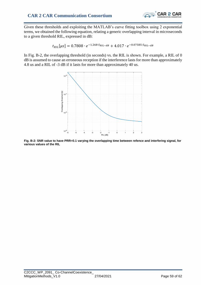
CAR 2 CAR Communication Consortium
C2CCC_WP_2091_ Co-ChannelCoexistence_ MitigationMethods_V1.0 27/04/2021 Page 59 of 62
Given these thresholds and exploiting the MATLAB’s curve fitting toolbox using 2 exponential
terms, we obtained the following equation, relating a generic overlapping interval in microseconds
to a given threshold RIL, expressed in dB:
𝑡𝑅𝐼𝐿[𝜇𝑠] = 0.7808 ∙ 𝑒−1.268∙𝑆𝑅𝐼𝐿−𝑑𝐵 + 4.017 ∙ 𝑒−0.07585∙𝑆𝑅𝐼𝐿−𝑑𝐵
In Fig. B-2, the overlapping threshold (in seconds) vs. the RIL is shown. For example, a RIL of 0
dB is assumed to cause an erroneous reception if the interference lasts for more than approximately
4.8 us and a RIL of -3 dB if it lasts for more than approximately 40 us.
Fig. B-2: SNR value to have PRR=0.1 varying the overlapping time between refence and interfering signal, for various values of the RIL

CAR 2 CAR Communication Consortium
C2CCC_WP_2091_ Co-ChannelCoexistence_ MitigationMethods_V1.0 27/04/2021 Page 60 of 62
Annex C: Definition and applicability of backward compatibility
Definition:
An ITS Station Si+1 is said to be compatible to another Si if Si+1 is able to interact with other ITS
Stations (which were left untouched) and designed to communicate with Si.
An ITS Station Si+1 is said to be backwards compatible to ITS Station Si if Si+1 is compatible to Si
and Si+1 is a successor of Si. See Fig. C-1.
Fig. C-1: backward compatibility of a ITS Station Si+1 to ITS Station Si
The backward compatibility is concerned with:
• Transmission of messages, data, formats of the data and/or signals between different ITS
stations
• Especially about ITS stations in the field and new ones added to the field
The backward compatibly assessment is done on the level of:
• Changed functionality which is effectively:
• Requirement/feature changes in the CAR 2 CAR specifications
The ITS stations have different interfaces which are not all in scope of the CAR 2 CAR backward
compatibility assessment.
• In scope: the communication between ITS stations
• Out of scope: communication of ITS station with OEM specific systems, e.g. software
update over the air facilities, backend communication e.g. to transfer certificates into the
car
Fig. C-2: Scope of backward compatibility assesment in CAR 2 CAR Communication Consortium

CAR 2 CAR Communication Consortium
C2CCC_WP_2091_ Co-ChannelCoexistence_ MitigationMethods_V1.0 27/04/2021 Page 61 of 62
Annex D – References
[3GPP36101] 3GPP TS 36.101 V15.0.0, “3rd Generation Partnership Project; Technical
Specification Group Radio Access Network; Evolved Universal Terrestrial
Radio Access (E-UTRA); User Equipment (UE) radio transmission and
reception (Release 15)”, September 2017
[Baz19]
A. Bazzi, G. Cecchini, M. Menarini, B. M. Masini, and A. Zanella, “Survey
and perspectives of vehicular wi-fi versus sidelink cellular-v2x in the 5g era,”
in Future Internet, vol. 11, no. 6, p. 122, 2019
[Baz20] A. Bazzi, C. Campolo, A. Molinaro, A. O. Berthet, B. M., Masini, and A.
Zanella, “On wireless blind spots in the C-V2X sidelink”, in IEEE
Transactions on Vehicular Technology, vol. 69, no. 8, pp. 9239-9243, 2020
[ETSI1032571]
ETSI TS 103 257-1 V1.1.1, “Intelligent Transport Systems (ITS); Access
Layer; Part 1: Channel Models for the 5,9 GHz frequency band”, May 2019.
[ETSI103574] ETSI TS 103 574 V1.1.1, “Intelligent Transport Systems (ITS); Congestion
Control Mechanisms for the C-V2X PC5 interface; Access layer part”,
November 2018
[ETSI103766] Draft ETSI TR 103 766, “Intelligent Transport Systems (ITS); Pre-
standardization study on co-channel co-existence between IEEE- and 3GPP-
based ITS technologies in the 5 855 MHz-5 925 MHz band; TR on co-channel
co-existence between ITS-G5 and LTE-V2X”. Document not yet published
[ETSI3026372] ETSI EN 302 637-2 V1.4.1, “Intelligent Transport Systems (ITS); Vehicular
Communications; Basic Set of Applications; Part 2: Specification of
Cooperative Awareness Basic Service”, January 2019
[ETSI302663] ETSI EN 302 663 V1.3.1, “Intelligent Transport Systems (ITS); ITS-G5
Access layer specification for Intelligent Transport Systems operating in the
5 GHz frequency band”, January 2020
[ETSI303613]
ETSI EN 303 613 V1.1.1, “Intelligent Transport Systems (ITS); LTE-V2X
Access layer specification for Intelligent Transport Systems operating in the
5 GHz frequency band”, January 2020
[Mar18] V. Martinez and F. Berens, “Survey on ITS-G5 CAM statistics,” in CAR 2
CAR Communication Consortium Technical Report, TR2052, December
2018
[SAF5400] NXP RoadLINK. SAF5400 V2X 802.11p Safety Modem
[SMW314] MobileMark SMW314 Series Multi-band Mount Antenna with GPS 694-960,
1710-3700 MHz (Global LTE), 5800-6000 MHz (DSRC)
[ECDEC 20201426]
COMMISSION IMPLEMENTING DECISION (EU) 2020/1426 of 7 October
2020 on the harmonised use of radio spectrum in the 5 875-5 935 MHz
frequency band for safety-related applications of intelligent transport systems
(ITS) and repealing Decision 2008/671/E

CAR 2 CAR Communication Consortium
C2CCC_WP_2091_ Co-ChannelCoexistence_ MitigationMethods_V1.0 27/04/2021 Page 62 of 62
■ End of Document ■


![HEPTA7291 2019-02...HEPTA7291 2019-02 NR V2X Summary Report (RAN1-AH_1901) [NR Sidelink V2X] Author: Dr. Carolyn Taylor (Hepta7291) Keywords 3GPP, 5G, NR, NR V2X, NR Sidelink, Sidelink](https://img.pdfslide.net/doc/110x75/5f6ccafb939b7872f73d2ee5/hepta7291-2019-02-hepta7291-2019-02-nr-v2x-summary-report-ran1-ah1901-nr.jpg)