Embed Size (px)
Citation preview
WhitePaper LED
LED Basics
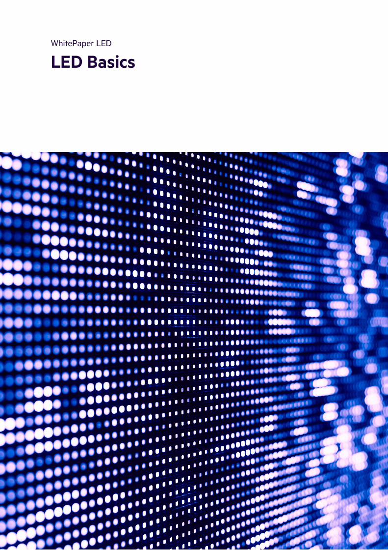
LED is a semiconductor based light source which significantly differs from conventional light sources. Unlike conventional luminaires where light is produced by a filament or gas, LEDs are tiny electronic chips made of specific semiconductor crystals. This principle of light generation offers many advantages and new opportunities.
The main advantages of LEDs include long lifetime, high efficiency, environmental friendliness, good colour rendering and a wide variety of design options.To make use of its full potential, light designers must be familiar with these new and specific characteristics of the LED. This document explains the most important concepts, techniques and possibilities.
WhitePaper
IntroductionLight Emitting Diode
Module LLE ADV5
Module SLE G7
Module LLE-FLEX
The light generated by an LED module can be described by its parameters colour rendering, colour temperature, chromaticity coordinate and colour consistency. The following section explains the relation and differences.
Colour renderingColour rendering describes how well a light source reproduces the different colours of an illuminated object. There are different methods for evaluating colour rendering and different parameters which result from that.
Colour Rendering Index (CRI)The Colour Rendering Index (CRI) is determined using a reference colour chart with 8 standardized test colours. Depending on thedeviations between the secondary spectra and the test colours, the light source is assigned to a particular CRI. If the colours are repro-duced badly, the deviations are large and the CRI is low. With good colour rendering the deviations are small and the CRI is high.TM-30 is a newer method which is more detailed and contains more information.To determine colour fidelity, 99 colour evaluation samples (CES) are used. The resulting Fidelity Index Rf can be between 0 and 100. A value of 100 indicates an exact match with the reference.
A second parameter, the Gamut Index Rg, provides additional infor-mation about the average relative saturation. Various graphics help to interpret the results.The maximum value of the CRI is 100. This corresponds to a colour rendering without any deviation. Sunlight has a CRI of up to 100, a white LED lies between 70 and 98. For practical use, this means that LED lighting units with a higher CRI reproduce the illuminated colours more naturally and more pleasing to the human eye. In certain appli-cations (e.g. the lighting of works of art in museums), this point is of crucial importance.
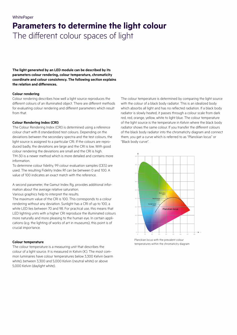
Colour temperature The colour temperature is a measuring unit that describes the colour of a light source. It is measured in Kelvin (K). The most com-mon luminaires have colour temperatures below 3,300 Kelvin (warm white), between 3,300 and 5,000 Kelvin (neutral white) or above 5,000 Kelvin (daylight white).
Planckian locus with the prevalent colour temperatures within the chromaticity diagram
0
0.1
0 0.1 0.2 0.3 0.4 0.5 0.6 0.7 0.8
0.2
0.3
0.4
0.5
0.6
0.7
0.9
X
0.8
Y
Planckian locus
Neutral white4,200 K
Warm white3,000 K
Daylight white6,500 K
WhitePaper
Parameters to determine the light colourThe different colour spaces of light
The colour temperature is determined by comparing the light source with the colour of a black body radiator. This is an idealized body which absorbs all light and has no reflected radiation. If a black body radiator is slowly heated, it passes through a colour scale from dark red, red, orange, yellow, white to light blue. The colour temperature of the light source is the temperature in Kelvin where the black body radiator shows the same colour. If you transfer the different colours of the black body radiator into the chromaticity diagram and connect them, you get a curve which is referred to as “Planckian locus” or “Black body curve”.

Chromaticity coordinateThe chromaticity coordinate defines a colour by its coordinates within the chromaticity diagram. There are three coordinates (x, y, z). Since the sum of all coordinates always equals 1, two coordinates are suffici-ent to locate a colour. The chromaticity coordinate allows for a more precise definition of colour than the colour temperature. It can be used to specify a desired colour or to designate undesired deviations between colours. This is specifically important in areas where the lighting must produce a specified and uniform colour and deviationscan impair the visual appearance of an installation.
Colour consistencyThe colour consistency describes the maximum deviation from a target colour. Its unit is called “SDCM” (short for “Standard Deviation of Colour Matching”). The SDCM value refers to the chromaticity diagram and the MacAdam ellipses.The MacAdam ellipses are named after their discoverer and highlight areas within the chromaticity diagram in which humans can perceive no differences in colour. Different levels of MacAdam ellipses are also used to classify colour deviations. MacAdam1 would be a very small ellipse with a narrow range of different colours. With increasing numbers (MacAdam1, MacAdam2 etc.), the ellipses and the differences between the colours become greater.
SDCM1 or MacAdam1 means that the colour deviations of an LED module must be within a MacAdam1 ellipse around the defined chromaticity coordinate. A larger deviation with a chromaticity coordi-nate outside the MacAdam1 ellipse (but within the next larger MacA-dam2 ellipse) would lead to a classification as SDCM2 or MacAdam2. Colour deviations in the range of SDCM1 are practically imperceptible to humans. A value of SDCM3 represents a good compromise and has established itself as a kind of standard.
Definition of the colour temperature neutral white bythe x and y coordinates (x=0.38; y =0.38) within thechromaticity diagram
Chromaticity coordinate of the colour tempe-rature neutral white (x=0.38; y=0.38) with the MacAdam ellipses SDCM3 and SDCM5
Practical exampleColour-related specifications from the data sheet of a Tridonic LED module: Colour temperature (2,700 K), chromaticity coordinates (defined by the x=0.463; y=0.420 coordinates), colour consistency (SDCM3), and a graphical representation of chromaticity coordinate and MacAdam ellipse.
0
0.1
0 0.1 0.2 0.3 0.4 0.5 0.6 0.7 0.8
0.2
0.3
0.4
0.5
0.6
0.7
0.9
X
0.8
Y
0.38
0.38
Neutral white 4,200 K
0.4000
0.4050
0.4100
0.4150
0.4200
0.4250
0.4300
0.350
0.4400
0.44
50
0.45
00
0.45
50
0.46
00
0.46
50
0.47
00
0.47
50
0.48
00
0.48
50
0.3550
0.3600
0.3650
0.3700
0.3750
0.3800
0.3850
0.35
50
0.36
00
0.36
50
0.37
00
0.37
50
0.38
00
0.38
50
0.39
00
0.39
50
0.3900
0.3950
SDCM5SDCM3

For conventional technologies, the lifetime is defined as the point at which a certain percentage of lamps show a complete, lights-out failure. For LEDs this definition is not practical. A well designed LED package typically doesn't fail completely. Instead it can operate exten-sively but will lose luminous flux continuously over time. Accordingly, lifetime definitions for LEDs use different parameters to describe the behaviour of the LED.
L value (Lp)
Lp defines the remaining luminous flux as a percentage of the original
value. Lp is used in combination with a defined operation time. The
following graph illustrates this: The cyan-coloured line depicts the lu-minous flux. This is gradually going down. After 32,000 hours the value has fallen to 90 %. This is defined as L90 at 32,000 hours.
WhitePaper
Lifetime of LEDsHigh efficiency and a long life span
Rel
. Lum
inou
s flu
x [%
]
Operation Time [h]
L90 32,000 h
10,000 50,000
50
60
70
80
90
100
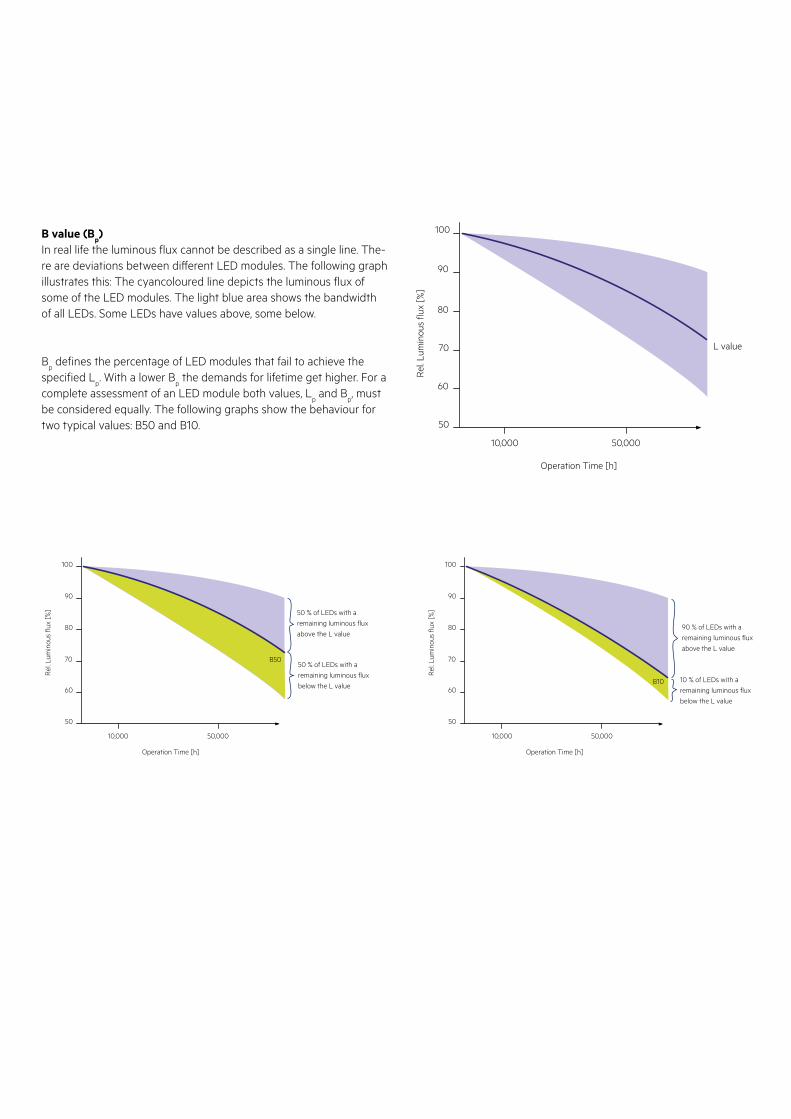
B value (Bp)
In real life the luminous flux cannot be described as a single line. The-re are deviations between different LED modules. The following graph illustrates this: The cyancoloured line depicts the luminous flux of some of the LED modules. The light blue area shows the bandwidth of all LEDs. Some LEDs have values above, some below.
Bp defines the percentage of LED modules that fail to achieve the
specified Lp. With a lower B
p the demands for lifetime get higher. For a
complete assessment of an LED module both values, Lp and B
p, must
be considered equally. The following graphs show the behaviour for two typical values: B50 and B10.
Rel
. Lum
inou
s flu
x [%
]
Operation Time [h]
L value
10,000 50,000
50
60
70
80
90
100
50 % of LEDs with aremaining luminous fluxabove the L value
50 % of LEDs with aremaining luminous fluxbelow the L value
Rel
. Lum
inou
s flu
x [%
]
50
B50
60
70
80
90
100
Operation Time [h]
10,000 50,000
90 % of LEDs with aremaining luminous fluxabove the L value
10 % of LEDs with aremaining luminous fluxbelow the L value
Rel
. Lum
inou
s flu
x [%
]
50
B1060
70
80
90
100
Operation Time [h]
10,000 50,000
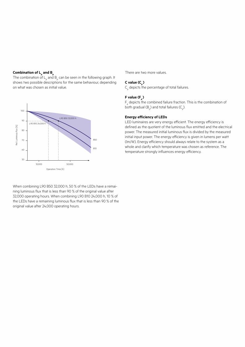
Combination of Lp and B
p
The combination of Lp and B
p can be seen in the following graph. It
shows two possible descriptions for the same behaviour, depending on what was chosen as initial value.
When combining L90 B50 32,000 h, 50 % of the LEDs have a remai-ning luminous flux that is less than 90 % of the original value after 32,000 operating hours. When combining L90 B10 24,000 h, 10 % of the LEDs have a remaining luminous flux that is less than 90 % of the original value after 24,000 operating hours.
There are two more values.
C value (Cp )
Cp depicts the percentage of total failures.
F value (Fp )
Fp depicts the combined failure fraction. This is the combination of
both gradual (Bp) and total failures (C
p).
Energy efficiency of LEDsLED luminaires are very energy efficient. The energy efficiency is defined as the quotient of the luminous flux emitted and the electrical power. The measured initial luminous flux is divided by the measured initial input power. The energy efficiency is given in lumens per watt (lm/W). Energy efficiency should always relate to the system as a whole and clarify which temperature was chosen as reference. The temperature strongly influences energy efficiency.
B50
B10
Rel
. Lum
inou
s flu
x [%
]
50
60
70
80
90
100
Operation Time [h]
L90 B10 24,000 h
L90 B50 32,000 h
10,000 50,000
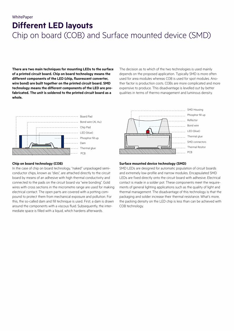
There are two main techniques for mounting LEDs to the surface of a printed circuit board. Chip on board technology means the different components of the LED (chip, fluorescent converter, wire bond) are built together on the printed circuit board. SMD technology means the different components of the LED are pre-fabricated. The unit is soldered to the printed circuit board as a whole.
Surface mounted device technology (SMD)SMD LEDs are designed for automatic population of circuit boards and extremely low-profile and narrow modules. Encapsulated SMD LEDs are fixed directly onto the circuit board with adhesive. Electrical contact is made in a solder pot. These components meet the require-ments of general lighting applications such as the quality of light and thermal management. The disadvantage of this technology is that the packaging and solder increase their thermal resistance. What’s more, the packing density on the LED chip is less than can be achieved with COB technology.
Chip on board technology (COB)In the case of chip on board technology, “naked” unpackaged semi-conductor chips, known as “dies”, are attached directly to the circuit board by means of an adhesive with high thermal conductivity and connected to the pads on the circuit board via “wire bonding”. Gold wires with cross sections in the micrometre range are used for making electrical contact. The open parts are covered with a potting com-pound to protect them from mechanical exposure and pollution. For this, the so-called dam and fill technique is used. First, a dam is drawn around the components with a viscous fluid. Subsequently, the inter-mediate space is filled with a liquid, which hardens afterwards.
Board Pad
Bond wire (Al, Au)
Chip Pad
LED (blue)
PCB
Thermal glue
Phosphor fill up
Dam
SMD Housing
Phosphor fill up
Reflector
Bond wire
SMD connectors
Thermal Resitor
Thermal glue
LED (blue)
PCB
WhitePaper
Different LED layoutsChip on board (COB) and Surface mounted device (SMD)
The decision as to which of the two technologies is used mainly depends on the proposed application. Typically SMD is more often used for area modules whereas COB is used for spot modules. Ano-ther factor is production costs. COBs are more complicated and more expensive to produce. This disadvantage is levelled out by better qualities in terms of thermo management and luminous density.
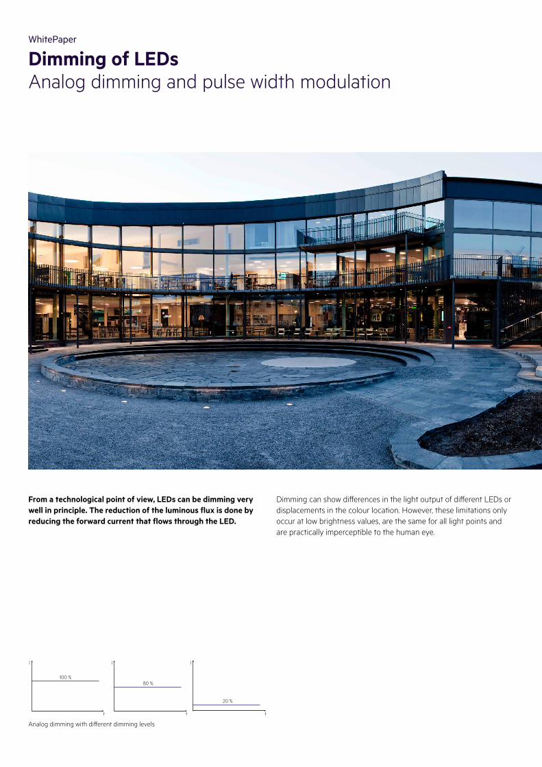
From a technological point of view, LEDs can be dimming very well in principle. The reduction of the luminous flux is done by reducing the forward current that flows through the LED.
Dimming can show differences in the light output of different LEDs or displacements in the colour location. However, these limitations only occur at low brightness values, are the same for all light points and are practically imperceptible to the human eye.
Analog dimming with different dimming levels
WhitePaper
Dimming of LEDsAnalog dimming and pulse width modulation
100 %
l l l
t t t
80 %
20 %
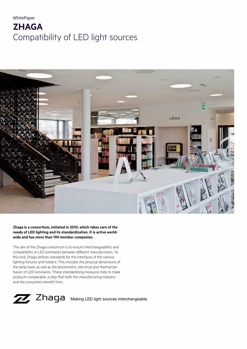
Zhaga is a consortium, initiated in 2010, which takes care of the needs of LED lighting and its standardization. It is active world-wide and has more than 190 member companies.
The aim of the Zhaga consortium is to ensure interchangeability and compatibility of LED luminaires between different manufacturers. To this end, Zhaga defines standards for the interfaces of the various lighting fixtures and holders. This includes the physical dimensions of the lamp base, as well as the photometric, electrical and thermal be-havior of LED luminaires. These standardizing measures help to make products comparable, a step that both the manufacturing industry and the consumers benefit from.
WhitePaper
ZHAGACompatibility of LED light sources

Prepared for the FutureOur Activities and Locations
Details
For further information, data sheets, product catalogues and ordering details, please go to www.tridonic.com
With 21 branch o� ices on five continents we are there for you wherever you are in the world.
There are three things you can rely on at Tridonic: optimum product quality, decades of expertise and our commit-ted and flexible support.
Around 1,700 employees throughout theworld are committed to helping you withtheir know-how and creativity to create the perfect light.
There are six research and development centres in which new LEDs and net-worked lighting technologies are being developed.
21
36
That‘s how many patents and inventionstestify to Tridonic‘s extraordinary powers of innovation.
Ennenda, Switzerland
Sensor technology
Porto, Portugal
IoT applications
Dornbirn, Austria
Networked hardware technology
Spennymoor, UK
Emergency technology
Jennersdorf, Austria
LED module technology
Niš, Serbia
LED driver technology
Shenzhen, China
LED driver technology
Production siteHeadquarters Research and developement Sales o� ice
1.778
2.6001In our unique software competence center in Porto (Portugal), information technology experts are developing new solutions for smart buildings and smart cities. They are working on a range of products from intelligent lighting management and control systems to highly advanced IoT solutions and their matching digital services.

Light you want to follow.HeadquartersTridonic GmbH & Co KGFärbergasse 15 | 6851 Dornbirn, Austria T +43 5572 395-0 | F +43 5572 20176www.tridonic.com | [email protected] 02
/20
Subj
ect t
o ch
ange
with
out n
otic
e. E
rror
s an
d om
issi
on e
xcep
ted.
Close lightWe attach great importance to a strong international presence – this allows us to stay su� iciently close to our customers
AUSTRALIATridonic Australia Pty Ltd2/7 Millner Avenue,Horsley Park, NSW 2175AustraliaT +61 2 9832 6600F +61 2 9832 [email protected]
AUSTRIATridonic GmbH & Co KG(Headquarters)Färbergasse 156851 Dornbirn, AustriaT +43 5572 395-0F +43 5572 [email protected]
Tridonic GmbH & Co KGSales Austria Archenweg 586022 Innsbruck, AustriaT +43 512 3321 554 F +43 512 3321 [email protected]
CHINATridonic (Shanghai) Co., Ltd.(Headquarters)Room 602, Buliding B Zhongshan International PlazaNo. 789 Tianshan RoadShanghai, 200335, ChinaT +86 21 52400 599F +86 21 52400 [email protected]
Tridonic (Shanghai) Co., Ltd.Beijing BranchRoom 1207, No. 3, Yard 1Tian Xin Street,Fang Shan DistrictBeijing, 102446, ChinaT +86 10 6522 6163F +86 10 6522 [email protected]
Tridonic (Shanghai) Co., Ltd.Guangzhou BranchRoom 505, R & F Profit Plaza76 Huangpu Xi Road, Tianhe DistrictGuangzhou, 510623, ChinaT +86 20 3839 2483F +86 20 3839 [email protected]
EASTERN EUROPETridonic GmbH & Co KGFärbergasse 156851 Dornbirn, AustriaT +43 5572 395-0F +43 5572 [email protected]
FRANCETridonic France SARL8 Rue de BruxellesZI Krafft67150 Erstein, FranceT +33 3 88 59 62 70F +33 3 88 59 62 [email protected]
GERMANYTridonic Deutschland GmbHEdisonallee 189231 Neu-Ulm GermanyT +49 731 176629-0F +49 731 [email protected]
INDIAAtco Controls (India) Private Limited38B, Nariman Bhavan, Nariman Point 400021 MumbaiIndiaT +91 22 22 02 55 [email protected]
ITALYTridonic Italia srlViale della Navigazione Interna, 11535027 Noventa PadovanaItalyT +39 049 89 45 127F +39 049 87 04 715www.tridonic.it [email protected]
KOREATridonic Korea LLCLee Seok-Jun#808 HanHwa BizMetro II551-24 Yangcheon-roGangseo-gu SeoulRepublic of Korea (South)T +82 (2) 2013 8051T +82 10 2230 [email protected]
MALAYSIATridonic S. E. A. Pte Ltd10 Tannery Lane#03-01347773 SingaporeMalaysiaT +65 62 928 148F +65 62 933 [email protected]
Tridonic Malaysia Sdn BhdV03-10-01 Designer Office,Lingkaran SV,Sunway Velocity, Cheras55100 Kuala LumpurMalaysiaT +60 3 2733 6484T +60 3 2733 [email protected]
MIDDLE EASTTridonic Middle East (FZE)P. O. Box 17972Jebel Ali Free ZoneDubai, United Arab EmiratesT +971 4 8833 664F +971 4 8833 [email protected]
NEW ZEALANDTridonic New Zealand Ltd.PO Box 71134, Rosebank27 Jomac Place, AvondaleAuckland, New ZealandT +64 9820 [email protected]
POLANDTridonic Rep. Office PolandPolandT +48 67 222 60 [email protected]
PORTUGALTridonic Iberia, S.L.Portugal OfficeAlameda da Empresa, 64 – Candal Park – Fração AL-134400-133 Vila Nova de GaiaPortugalT +351 938 448 [email protected]
SINGAPORETridonic South East Asia Pte LtdNo. 10 Tannery Lane #03-01347773 SingaporeSingaporeT +65 6292 8148F +65 6293 [email protected]
SOUTH AFRICATridonic SA (Pty) LtdUnit 7, Ground Floor Old Trafford Office ParkC/O Trichardt and Leiths RoadBartlett, Boksburg 1459South AfricaT +27 11 894 3525F +27 86 459 [email protected]
SPAINTridonic Iberia, S.L.OFICINA CENTRAL – MADRIDCalle Carpinteros nº 8, 2a28670 Villaviciosa de Odón (Madrid)SpainT +34 916 162 095F +34 916 165 [email protected]
Tridonic Iberia, S.L.Delegación – BarcelonaCalle Pau Vila nº 13-15, 3ª08173 Sant Cugat del Valles (Barcelona)SpainT +34 935 878 628F +34 935 903 [email protected]
SWITZERLANDTridonic Schweiz AGObere Allmeind 28755 Ennenda SwitzerlandT +41 55 645 4747F +41 55 645 [email protected]
TURKEYTridonic Aydınlatma TİC.LTD. ŞTİ.Kemankeş Mah., Necatibey cad.Akçe Sok., Akçe Han 1034420 Karaköy / BeyoğluIstanbul, TurkeyT +90 212 244 78 05F +90 212 244 78 [email protected]
UNITED KINGDOMTridonic UK LimitedUnit 7 LindenwoodChineham Business ParkCrockford Lane, ChinehamRG24 8LB BasingstokeHampshireUnited KingdomT +44 1256 374300F +44 1256 [email protected]
USATridonic Inc. USA3300 Route 9WHighland, NY 12528United [email protected]