Embed Size (px)
Citation preview
Whitewater Kayak Slalom Whitewater Kayak Slalom Race TimerRace Timer
Engineers:Kevin LockwoodChris MunshawAshley Penna
John So

Project Funded By:Project Funded By:
Mike NeckarFounder, Necky Kayakswww.necky.com
Background on Whitewater Background on Whitewater KayakingKayaking
• Whitewater kayak slalom racing began shortly before World War II
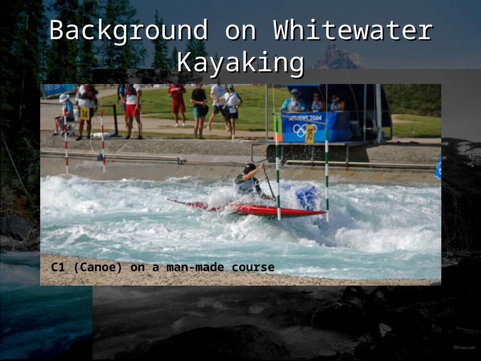
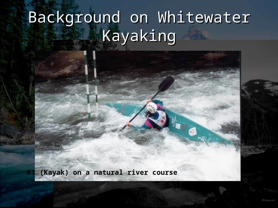
• This Olympic sport involves racers paddling down a natural or man-made rive
• Kayakers must maneuver through hanging pairs of gates.
• Judges at shoreline determine correct maneuvering through gates.
Background on Whitewater Background on Whitewater KayakingKayaking
C1 (Canoe) on a man-made course
Background on Whitewater Background on Whitewater KayakingKayaking
K1 (Kayak) on a natural river course
Kayak Rules
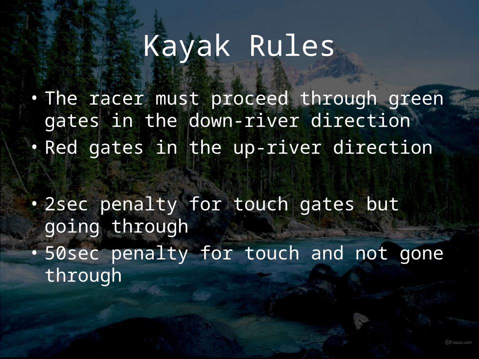
• The racer must proceed through green gates in the down-river direction
• Red gates in the up-river direction
• 2sec penalty for touch gates but going through
• 50sec penalty for touch and not gone through
Present Situation
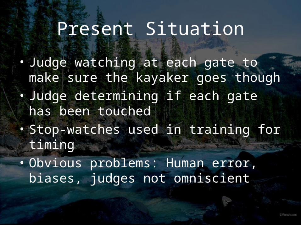
• Judge watching at each gate to make sure the kayaker goes though
• Judge determining if each gate has been touched
• Stop-watches used in training for timing
• Obvious problems: Human error, biases, judges not omniscient
Our Solution
Create a automated system which tracks a kayaker’s progress through a race course and determines if gates are touched.
Focus on creating a reliable and low cost product. Offset the cost of using humans to judge gates.
Secondary goal is timing accuracy.

Marketing
• Mr. Neckar- use for training
by olympic athletes- introduced in races such as national team trials (Vedder River, Chilliwack)
• Scott Shipley, US national team member- promotion in the United States

Timeline
1-Jan-07 16-Jan-07 31-Jan-07 15-Feb-07 2-Mar-07 17-Mar-07 1-Apr-07 16-Apr-07
Research
Proposal
Functional Specification
Design Specification
Assembly of Modules
Integration/Prototype Testing
Debugging/Prototype Modification
Documentation
Progress Report
Overall, we are behind the proposed schedule by about two weeks.
Our Proposed Timeline
Delays are caused by…
• Waiting for sensors, microcontrollers, and RF modules to arrive.
• Testing other design options.
• Errors and bugs
• Underestimated Integration Time
• Earlier than expected deadline

TimelineThe Actual Timeline
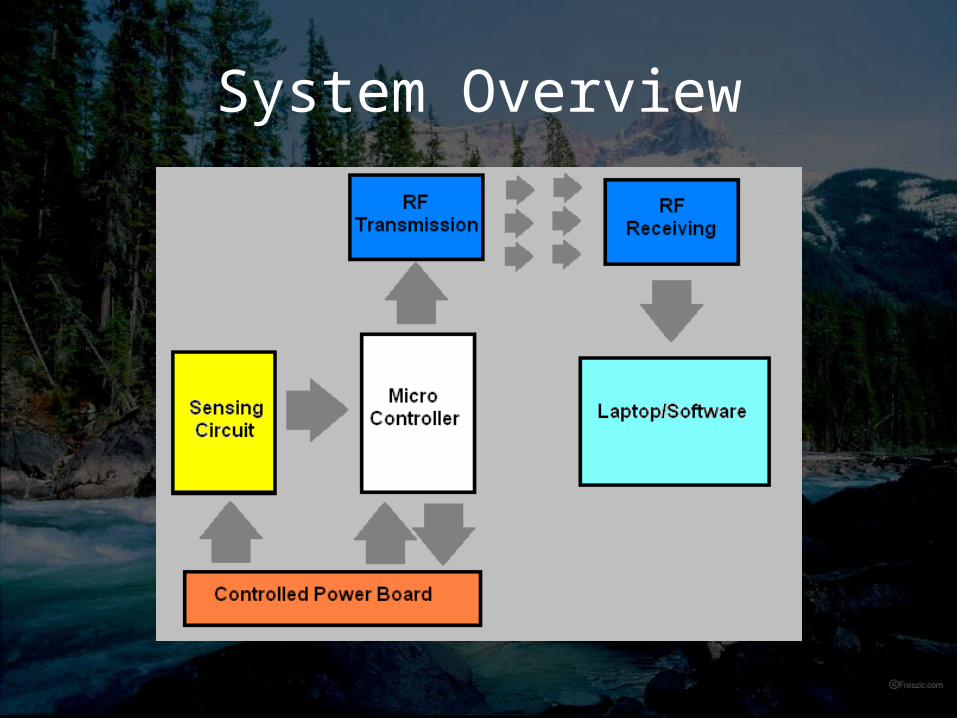
System Overview
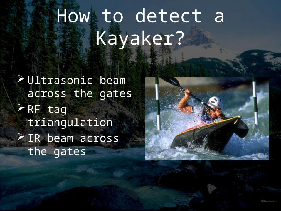
How to detect a Kayaker?
Ultrasonic beam across the gates
RF tag triangulation
IR beam across the gates
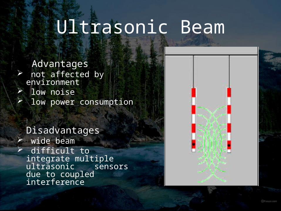
Ultrasonic Beam
Advantages not affected by
environment low noise low power consumption
Disadvantages
wide beam difficult to integrate
multiple ultrasonic sensors due to coupled interference
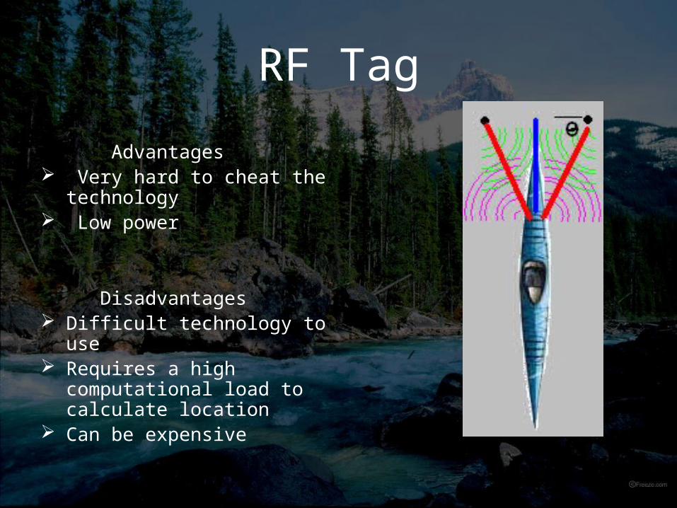
RF Tag
Advantages Very hard to cheat the
technology Low power
Disadvantages
Difficult technology to use Requires a high
computational load to calculate location
Can be expensive

Optical Beam (Our Solution)
Advantages Narrow beam Easy to implement Unaffected by
environment Lower costs
Disadvantages Consumes higher
power the ultrasonic Sensitive to alignment
IR LED vs. LaserIR LED vs. Laser• Laser (Visible Spectrum) 650nm
- coupled with a photodetector + amplifier- very high signal strength at large distances (5m +)- very narrow viewing angle- low power consumption (~20mA)- class III and above can cause retinal damage
IR LED vs. LaserIR LED vs. Laser• IR LED 950nm
- coupled with an NPN phototransistor - very low signal strength at distances over 2m (required amplification)- wide viewing angle (35°) minimizing problem of gate flexibility- high power consumption (~100mA)- cannot cause retinal damage
IR LED: Improving Signal IR LED: Improving Signal QualityQuality
• Ambient light shielding- used a non-reflective black paint to coat a drinking straw (this also formed a water-tight seal over the phototransistor)
• Modulation- modulated the IR emitter with a 2kHz square wave- demodulating at the receiving side would filter out noise cause by reflections of sunlight off water, etc
IR LED: Overall SystemIR LED: Overall System• Amplification -> Filtering -> Thresholding
- Amplification boosts the output signal strength- Filtering creates a steady signal representing the amount of IR light detected- Thresholding creates a digital signal representing whether or not the line of sight is considered “broken”
IR LED: ModulationIR LED: Modulation
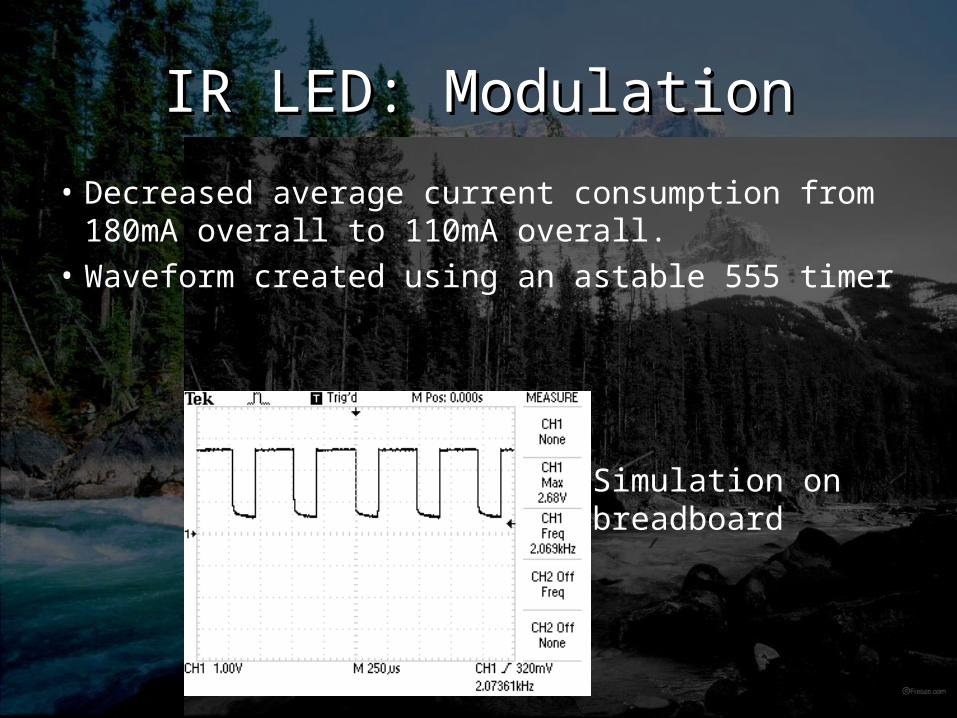
• Decreased average current consumption from 180mA overall to 110mA overall.
• Waveform created using an astable 555 timer
Simulation on breadboard
IR LED: DemodulationIR LED: Demodulation
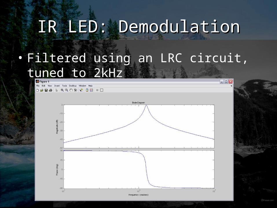
• Filtered using an LRC circuit, tuned to 2kHz
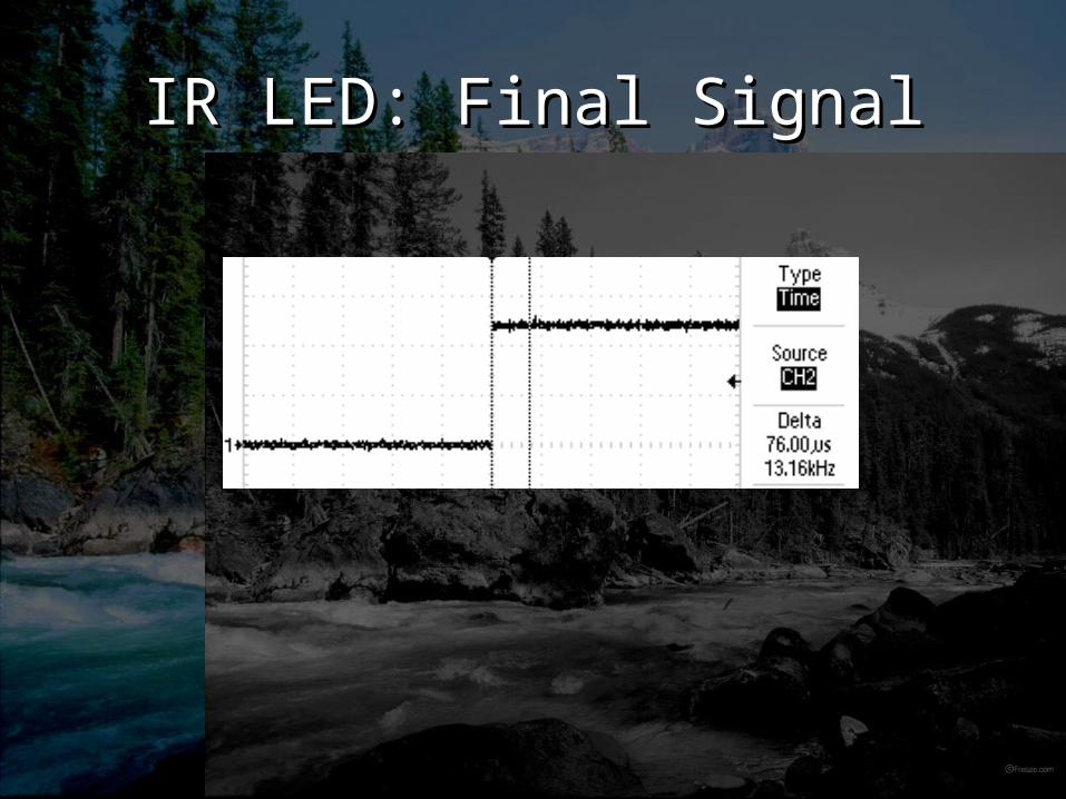
IR LED: Final SignalIR LED: Final Signal
AccelerometerAccelerometer• Used to detect any contact with the gate• 3 axis, ±5g output range• Mounted 1 accelerometer per gate, in the lower region of the gate (added
sensitivity)
Accelerometer: Signal Accelerometer: Signal ConditioningConditioning
• Low Pass Filter: allows us to “dull” the signal and remove unwanted noise• Comparator: gives a digital signal representing whether or not the acceleration of the gate
is beyond an acceptable level-> this allows us to have the system ignore low acceleration conditions such as gates swaying in the wind
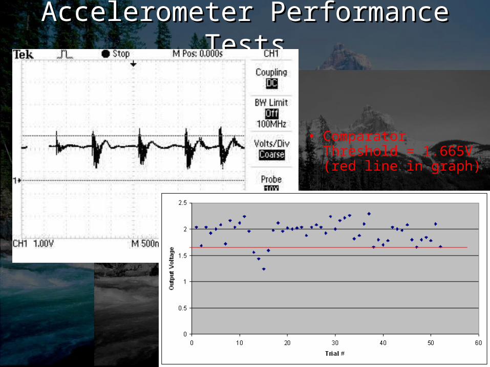
Accelerometer Performance Accelerometer Performance TestsTests
• Comparator Threshold = 1.665V(red line in graph)
Future Improvements on Signal Future Improvements on Signal ConditioningConditioning
• Have circuits printed on PCB
• Use only variable resistors reference voltages in comparators
• Improve demodulation circuit, possibly using an active filter
Final Sensor SignalsFinal Sensor Signals
• Two digital signals representing the clearance of a gate, and contact with a gate (both fully adjustable)
• However, current consumption is becoming high (approx. 180mA)
• This leads us to attempt ‘Presence Detection’
Presence Detection
• Used to detect the presence of an approaching kayaker.
• Used to trigger the turn on high power consuming subsystem.
• Used Ultrasonic sensors • Accuracy• Immunity• Ease
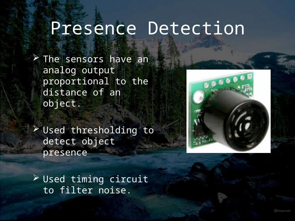
Presence Detection
The sensors have an analog output proportional to the distance of an object.
Used thresholding to detect object presence
Used timing circuit to filter noise.
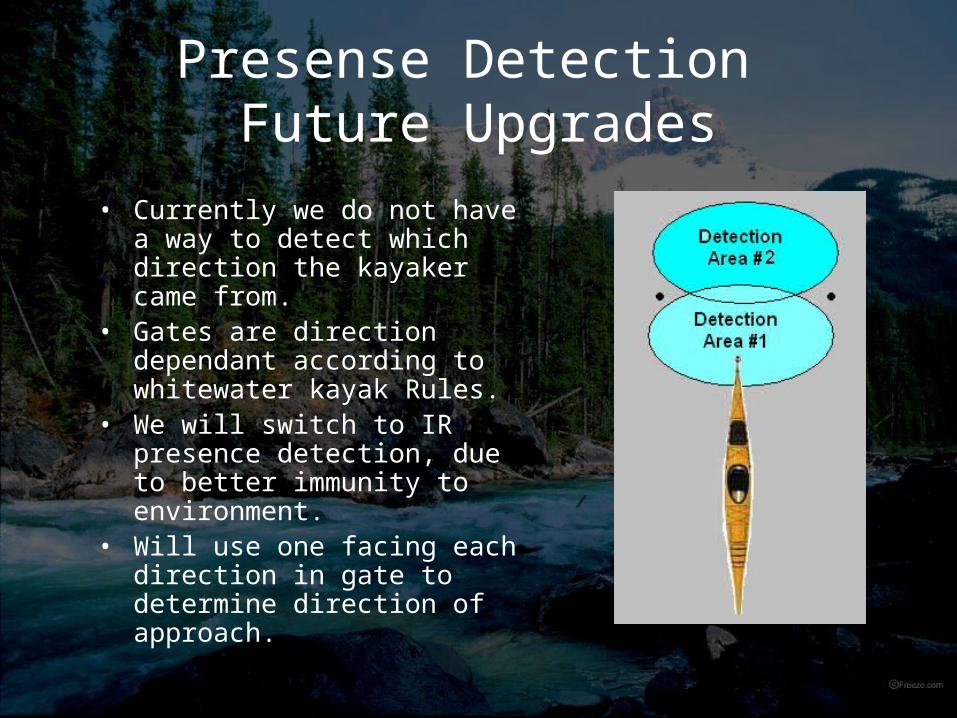
Presense Detection Future Upgrades
• Currently we do not have a way to detect which direction the kayaker came from.
• Gates are direction dependant according to whitewater kayak Rules.
• We will switch to IR presence detection, due to better immunity to environment.
• Will use one facing each direction in gate to determine direction of approach.
Data Communication
Requirements• Reliable • Long Range• Low Power• Fast Transmission

Data Communication Solution
ZigBee Xbee Module from Maxstream 30m range (upgrade 1mile) Current Consumption during Transmission
45mA UART Communication Format easy to integrate
with our Micro Controller

Data Communication Future Updates
• We can upgrade to Xbee Pro modules for an increased range.
• Requires more power.
• Allow software to communication back to gates.
• Remote reconfiguration• Remote turn on/off
MicroController Firmware
• Requirements– Very little memory needed – Simple program– USART Register for RF Modules– A/D Conversion capabilities– At least 3 inputs (IR Sensors, Ultrasonic,
Accelerometer)
MicroController Firmware
• Main Jobs– Get a development environment running– Integration with ultrasonic to turn on power
board– Integration with IR sensors– Integration with RF modules
MicroController Firmware
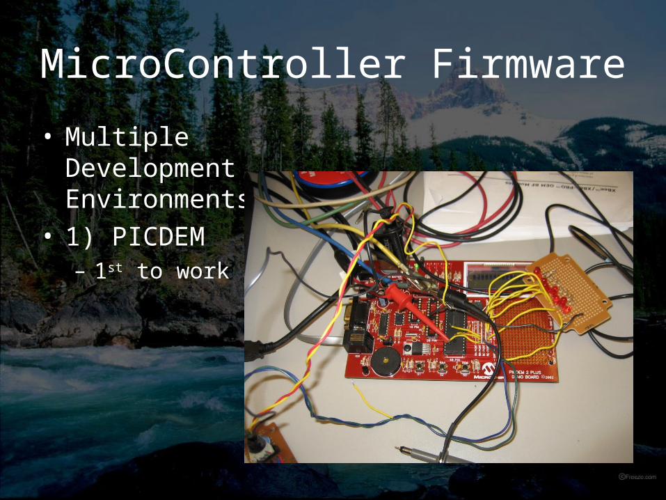
• Multiple Development Environments
• 1) PICDEM – 1st to work
MicroController Firmware
• Good Features– Easy viewing of
ports – Attached LEDs to
eliminate the need to probe
– Multiple ways to power
– MPLab compatibility
• Problematic Features– Had to replace 40-
pin socket– Initial running of
programs– Quantity
MicroController Firmware
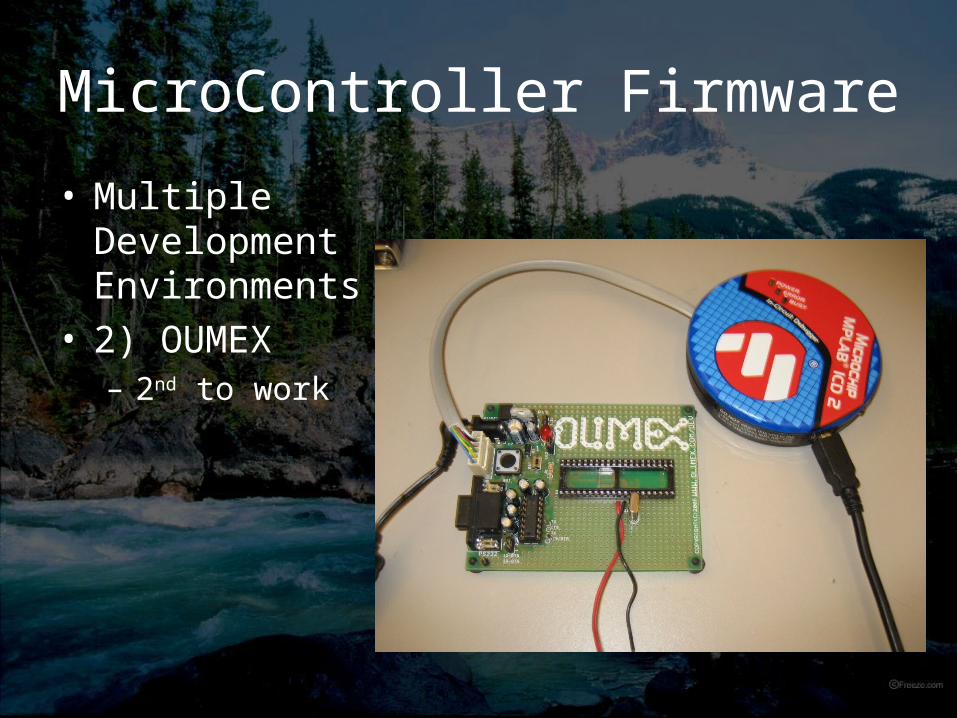
• Multiple Development Environments
• 2) OUMEX – 2nd to work
MicroController Firmware
• Good Features– One LED to map
outputs of interest to
– Programming capabilities using MPLab
– Less reliance on development board
• Problematic Features– Building a cable
from MPLab to ICSP
– Initial running of programs
– Quantity – shipping time

MicroController Firmware
• Multiple Development Environments
• 3) Prototype– Last and finally!!!
MicroController Firmware
• Good Features– Cheap– Space saving – Easy connection to
other circuits
• Problematic Features– Must move to
another development board to program
– Determining which components were necessary
MicroController Firmware
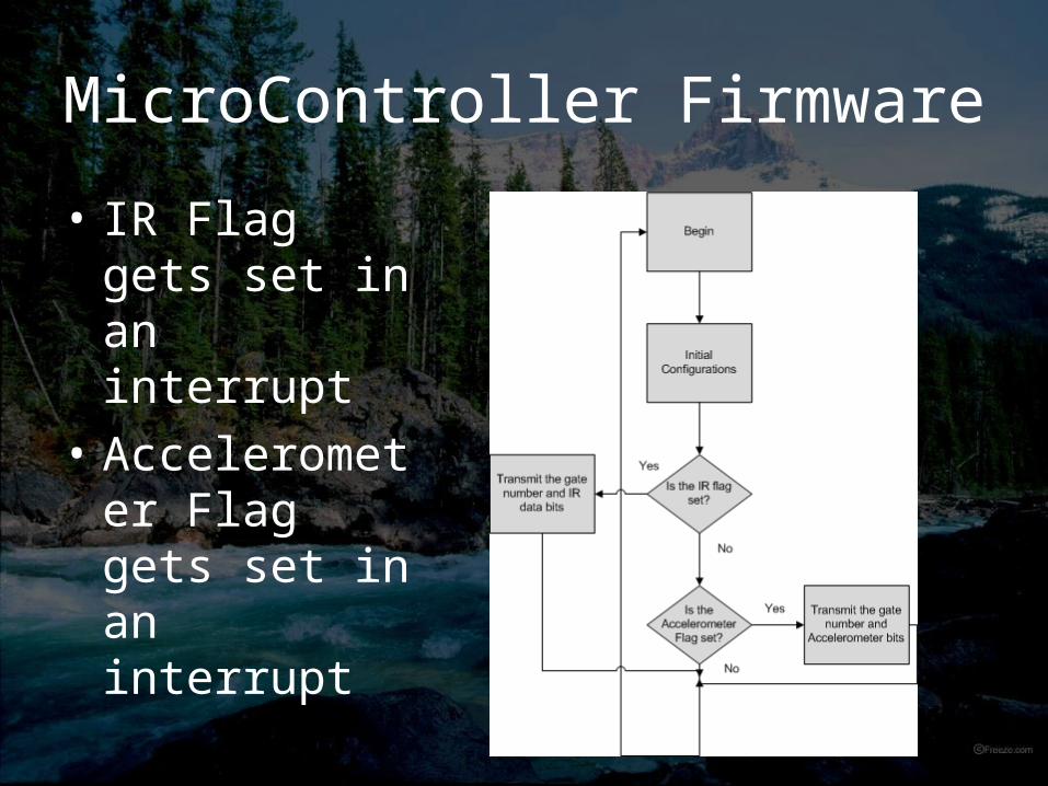
• IR Flag gets set in an interrupt
• Accelerometer Flag gets set in an interrupt
MicroController Firmware• Ultrasonic Powering Sensor Circuit
– Creates an interrupt which sets a flag– Main program deals with this – Output will be high when ultrasonic is high
• IR sensors Circuit– Creates an interrupt which sets a flag– In main program, transmission showing the
gate number and IR occurs
MicroController Firmware• Future Improvements
– Automatic Gate Addressing– Sleep pins on the RF module– Polling gates for possible battery voltage
The Power
IR sensors consume around 150mA.
Portable/Inexpensive power source in a 9v battery
Provide clean power at 3v and 5v for all subsystems.
Supply should last for 8hrs of use
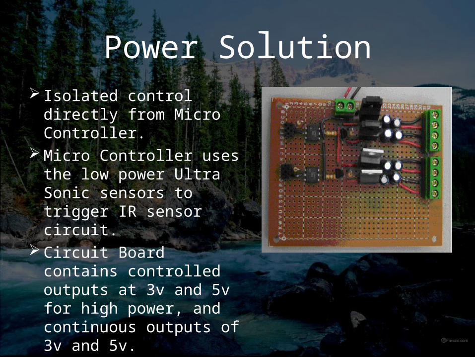
Power Solution Isolated control directly
from Micro Controller. Micro Controller uses
the low power Ultra Sonic sensors to trigger IR sensor circuit.
Circuit Board contains controlled outputs at 3v and 5v for high power, and continuous outputs of 3v and 5v.

Power SolutionWe want our portable power supplies to
last 8 hours of continuous usage
System Power Consumption Before Power Control
• Total Power Required = 1.21Ahr
System Power Consumption After Power Control
• Total Power Required = 0.511Ahr

Power Solution
Without a controlled power supply for 8hrs of continuous use requires 1.21Ahr
With a controlled power supply for 8hrsOf continuous use requires 0.511Ahr
Saves nearly 250% of our AmpHours required.
Improves portable power supply options.

Power Solution
We use two Rayovac 9v Alkaline batteries in parallel for each gate
Batteries spec at -30C to 55C
Each Battery has approx. 0.5Ahr

Graphical User Interface
Graphical User Interface
• Purpose:– Allows user to set up a race quickly.– Communicates with the RF module and
collects data from gates.– Displays data in table form.– Automatically times the race and applies
penalties.
Graphical User Interface
• Functions:– Kayaker list management. Add and remove
kayakers.– Modify number of gates.– File I/O– Display data:
• Names• Race Time• Penalties applied to each gate
Graphical User Interface
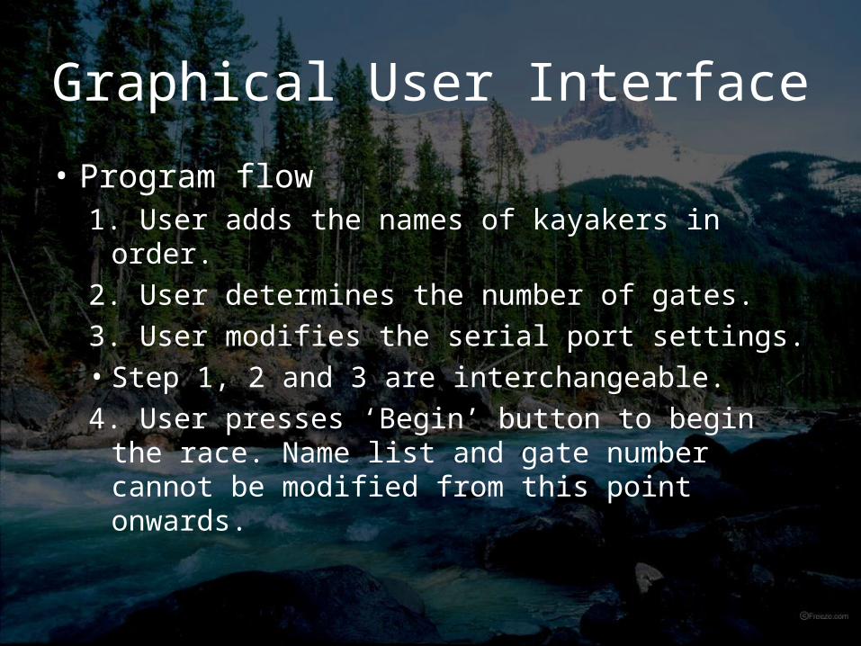
• Program flow1. User adds the names of kayakers in order.
2. User determines the number of gates.
3. User modifies the serial port settings.• Step 1, 2 and 3 are interchangeable.
4. User presses ‘Begin’ button to begin the race. Name list and gate number cannot be modified from this point onwards.
Graphical User Interface
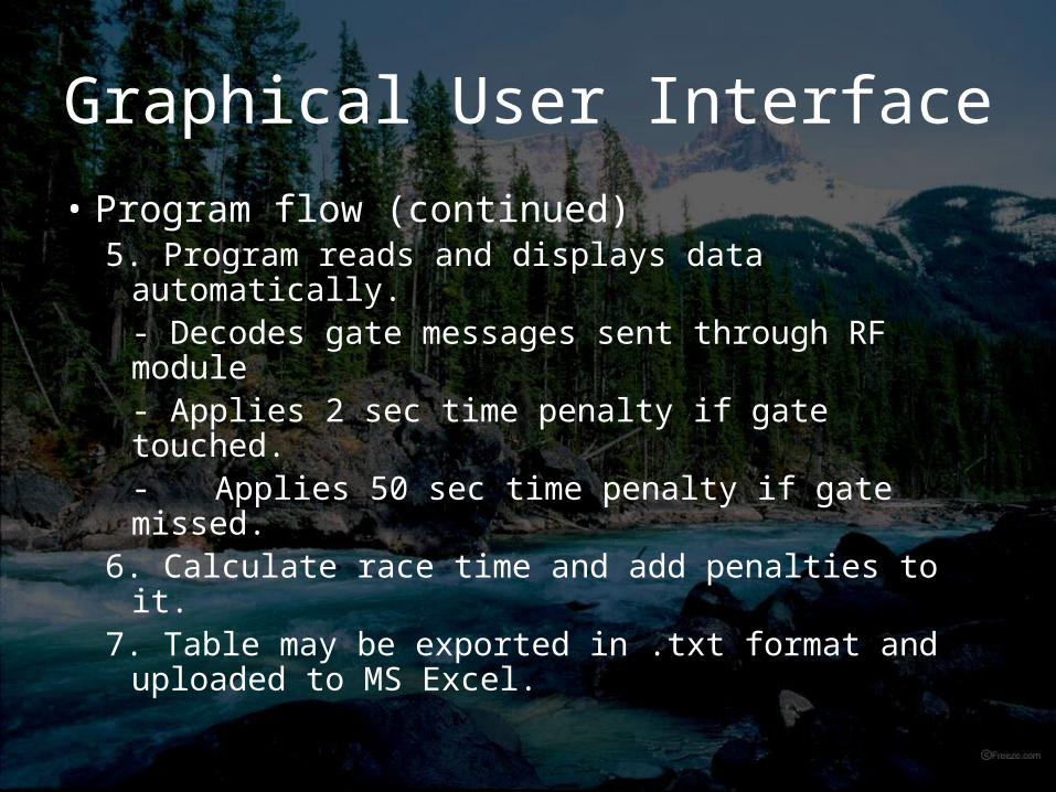
• Program flow (continued)5. Program reads and displays data
automatically.- Decodes gate messages sent through RF module- Applies 2 sec time penalty if gate touched.
- Applies 50 sec time penalty if gate missed.
6. Calculate race time and add penalties to it.7. Table may be exported in .txt format and
uploaded to MS Excel.
Graphical User Interface
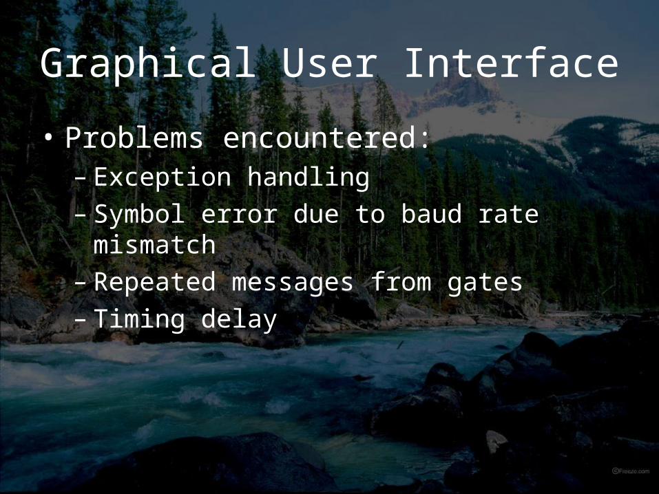
• Problems encountered:– Exception handling– Symbol error due to baud rate mismatch– Repeated messages from gates– Timing delay
Graphical User Interface
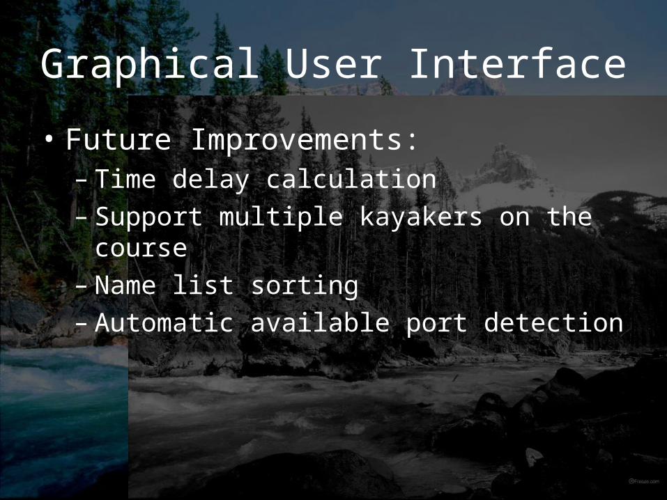
• Future Improvements:– Time delay calculation– Support multiple kayakers on the course– Name list sorting– Automatic available port detection
Summary
Created a automated system which tracks a kayaker’s progress through a race course and determines if gates are touched.
Focus on creating a reliable and low cost product. Offset the cost of using humans to judge gates.
Increased timing accuracy

The EndThe End
• Questions?
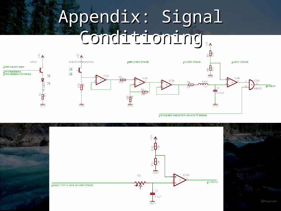
Appendix: Signal Appendix: Signal ConditioningConditioning
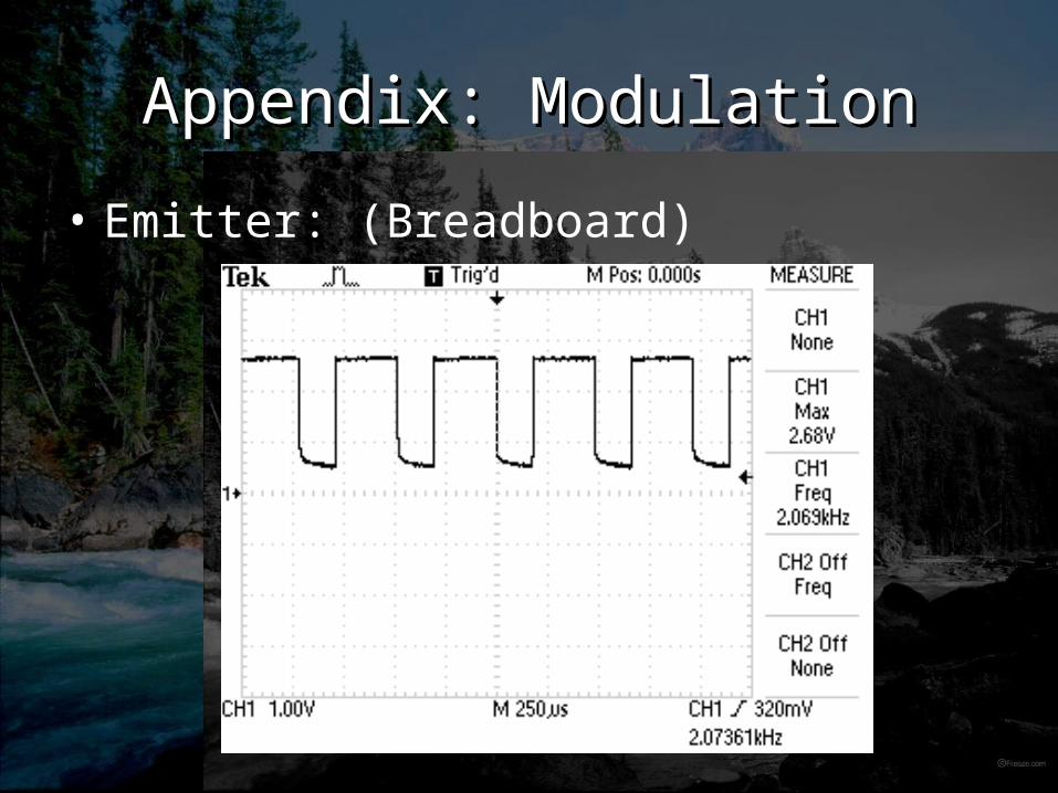
Appendix: ModulationAppendix: Modulation
• Emitter: (Breadboard)
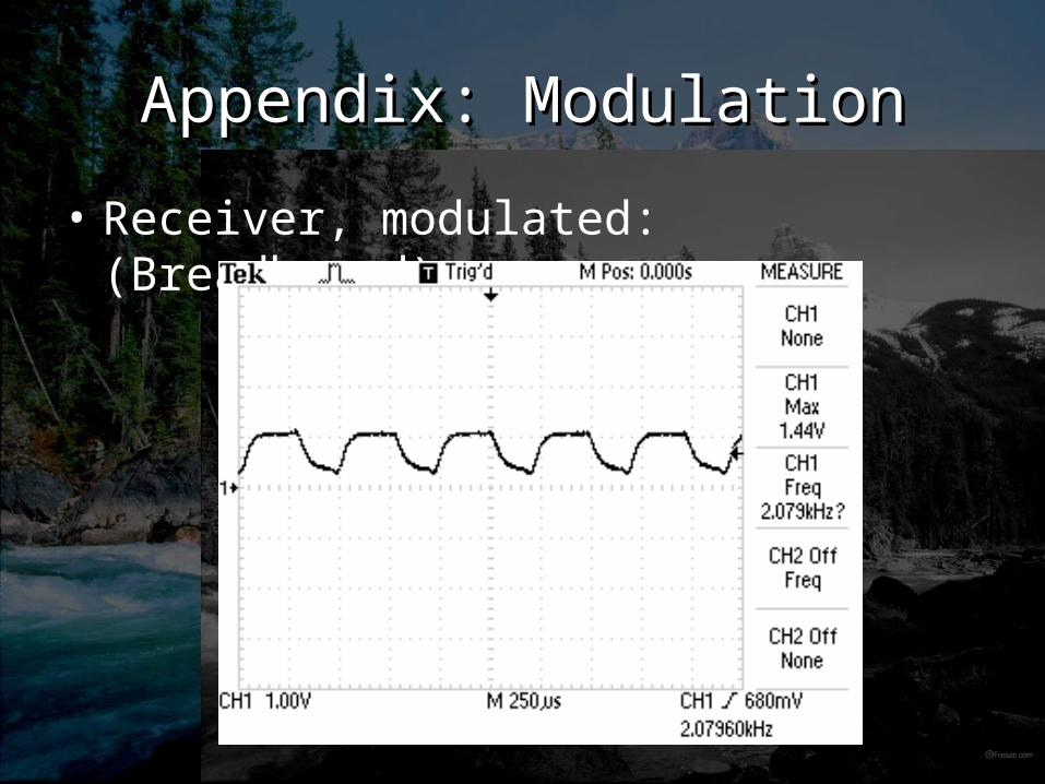
Appendix: ModulationAppendix: Modulation
• Receiver, modulated: (Breadboard)
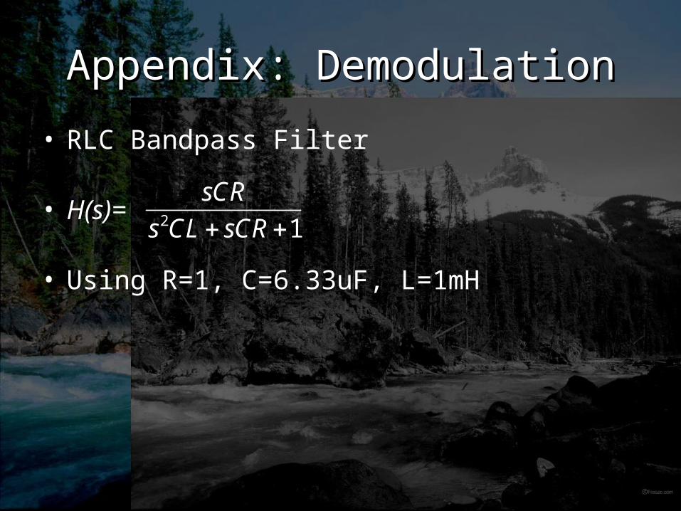
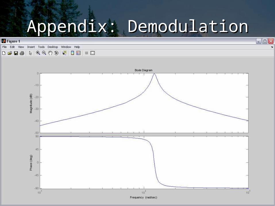
Appendix: DemodulationAppendix: Demodulation
• RLC Bandpass Filter
• H(s)=
• Using R=1, C=6.33uF, L=1mH
2 1
sCR
s CL sCR
Appendix: DemodulationAppendix: Demodulation
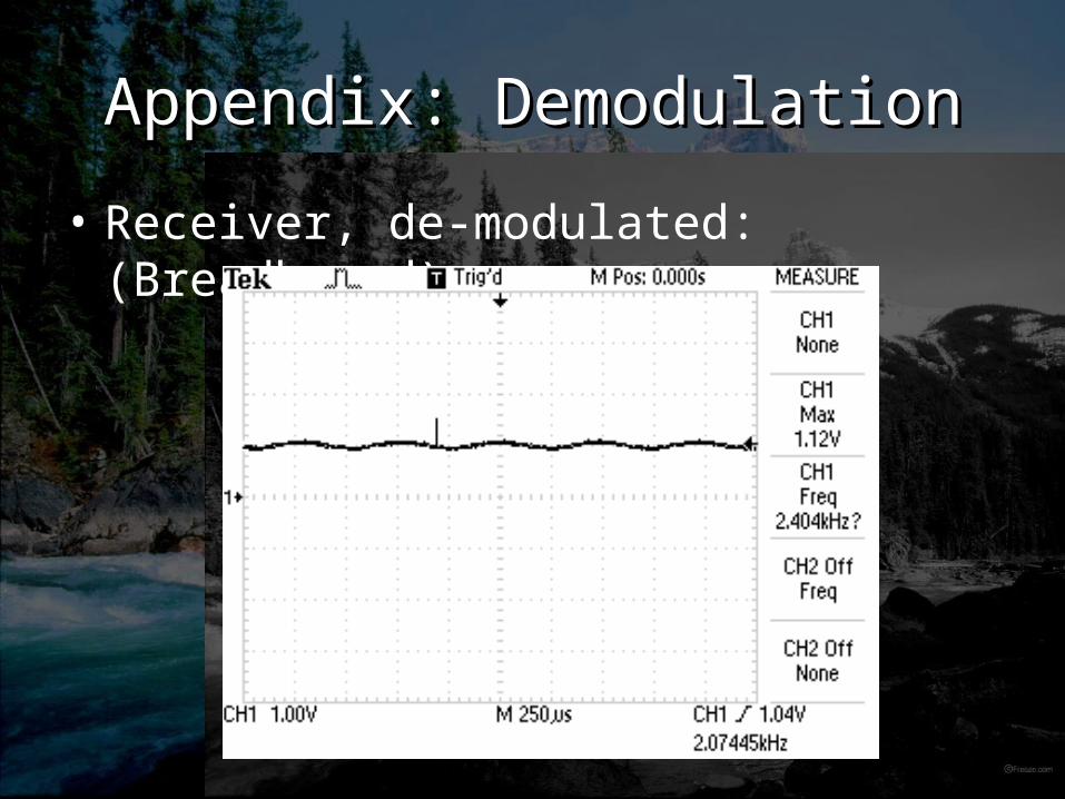
Appendix: DemodulationAppendix: Demodulation
• Receiver, de-modulated: (Breadboard)
Appendix: UltraSonic Circuit
• Used a simple LM324 OpAmp with a threshold voltage. Threshold set to approx. 5.5ft.
• 555 Monostable Timing circuit holds detection high for 5sec. This filters the natural circuit noise from the ultrasonic sensor.
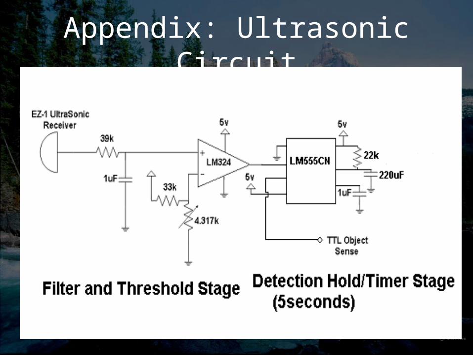
Appendix: Ultrasonic Circuit
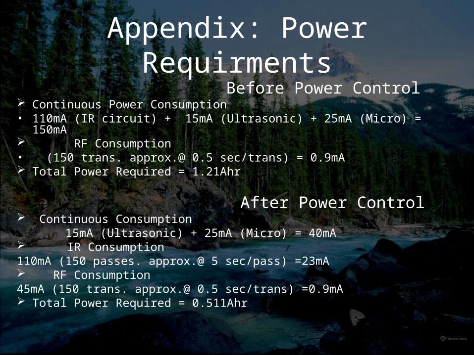
Appendix: Power Requirments Before Power Control Continuous Power Consumption• 110mA (IR circuit) + 15mA (Ultrasonic) + 25mA (Micro) = 150mA RF Consumption• (150 trans. approx.@ 0.5 sec/trans) = 0.9mA Total Power Required = 1.21Ahr
After Power Control Continuous Consumption 15mA (Ultrasonic) + 25mA (Micro) = 40mA IR Consumption110mA (150 passes. approx.@ 5 sec/pass) =23mA RF Consumption45mA (150 trans. approx.@ 0.5 sec/trans) =0.9mA Total Power Required = 0.511Ahr
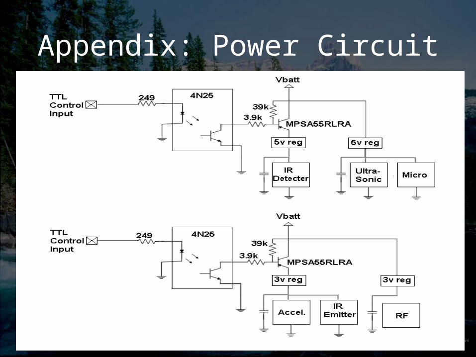
Appendix: Power Circuit
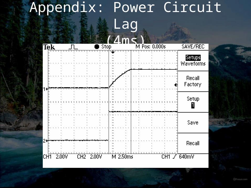
Appendix: Power Circuit Lag(4ms)
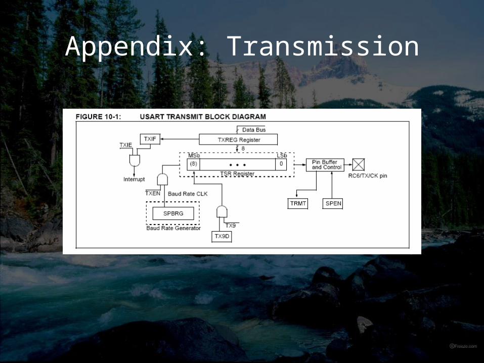
Appendix: Transmission
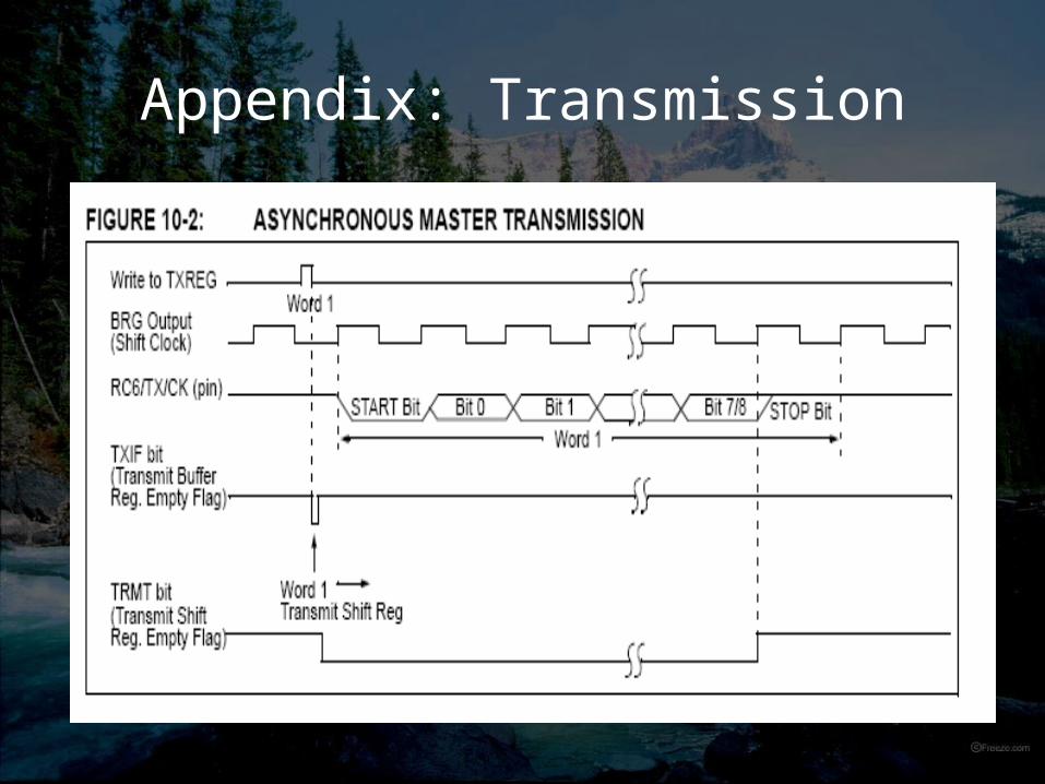
Appendix: Transmission
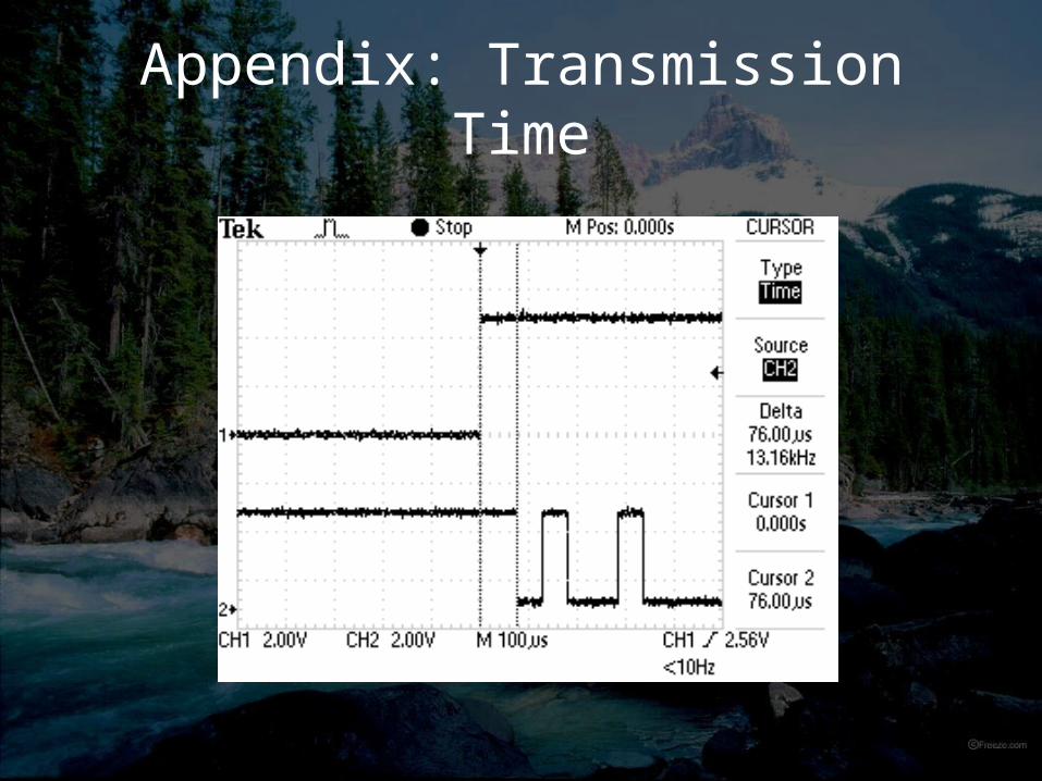
Appendix: Transmission Time