Embed Size (px)
Citation preview
Why is surface tension a force parallel to the interface?
Antonin MarchandPhysique et Mecanique des Milieux Heterogenes, UMR 7636 ESPCI - CNRS, Universite Paris-Diderot,10 rue Vauquelin, 75005, Paris, France
Joost H. Weijs and Jacco H. SnoeijerPhysics of Fluids Group and J. M. Burgers Centre for Fluid Dynamics, University of Twente, P.O. Box 217,7500 AE Enschede, The Netherlands
Bruno AndreottiPhysique et Mecanique des Milieux Heterogenes, UMR 7636 ESPCI - CNRS, Universite Paris-Diderot,10 rue Vauquelin, 75005, Paris, France
(Received 9 November 2011; accepted 10 July 2010)
A paperclip can float on water. Drops of mercury do not spread on a surface. These capillary
phenomena are macroscopic manifestations of molecular interactions and can be explained
in terms of surface tension. We address several conceptual questions that are often encountered
when teaching capillarity and provide a perspective that reconciles the macroscopic viewpoints
from thermodynamics and fluid mechanics and the microscopic perspective from statistical
physics. VC 2011 American Association of Physics Teachers.
[DOI: 10.1119/1.3619866]
I. INTRODUCTION
Capillarity is one of the most interesting subjects to teachin condensed matter physics because its detailed understand-ing involves macroscopic thermodynamics,1–3 fluid mechan-ics, and statistical physics.4 The microscopic origin ofsurface tension lies in the intermolecular interactions andthermal effects,5,6 while macroscopically it can be under-stood as a force acting along the interface or an energy perunit surface area. In this article, we discuss the link betweenthese three aspects of capillarity using simple examples. Wefirst discuss the standard problems faced by students andmany researchers in understanding surface tension. We willsee that the difficulty of understanding surface tension forcesis often caused by an improper or incomplete definition of asystem on which the forces act. We ask four basic questions,such as the one raised in the title, which we answer in thefollowing. Contrary to many textbooks on the subject, weprovide a picture that reconciles the microscopic, thermody-namic, and mechanical aspects of capillarity.
II. BASIC CONCEPTS AND PROBLEMS
A. The interface
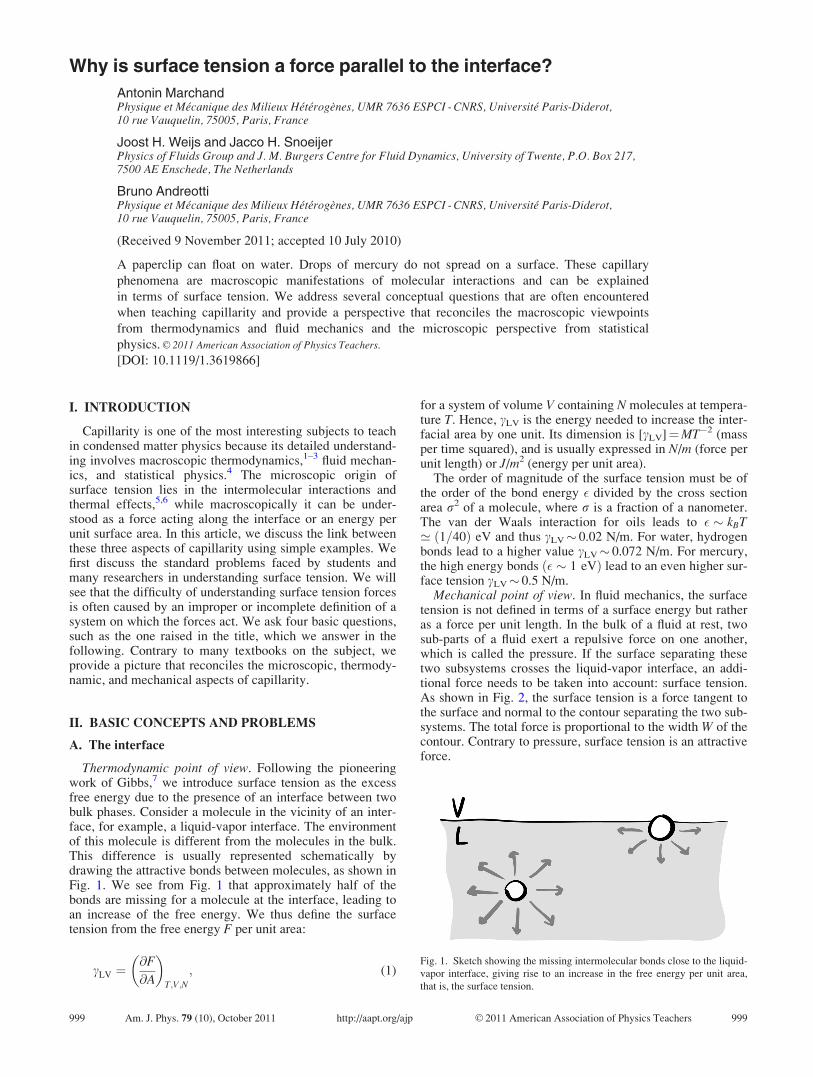
Thermodynamic point of view. Following the pioneeringwork of Gibbs,7 we introduce surface tension as the excessfree energy due to the presence of an interface between twobulk phases. Consider a molecule in the vicinity of an inter-face, for example, a liquid-vapor interface. The environmentof this molecule is different from the molecules in the bulk.This difference is usually represented schematically bydrawing the attractive bonds between molecules, as shown inFig. 1. We see from Fig. 1 that approximately half of thebonds are missing for a molecule at the interface, leading toan increase of the free energy. We thus define the surfacetension from the free energy F per unit area:
cLV ¼@F
@A
� �T;V;N
; (1)
for a system of volume V containing N molecules at tempera-ture T. Hence, cLV is the energy needed to increase the inter-facial area by one unit. Its dimension is [cLV]¼MT�2 (massper time squared), and is usually expressed in N/m (force perunit length) or J/m2 (energy per unit area).
The order of magnitude of the surface tension must be ofthe order of the bond energy � divided by the cross sectionarea r2 of a molecule, where r is a fraction of a nanometer.The van der Waals interaction for oils leads to � � kBT’ 1=40ð Þ eV and thus cLV� 0.02 N/m. For water, hydrogenbonds lead to a higher value cLV� 0.072 N/m. For mercury,the high energy bonds � � 1 eVð Þ lead to an even higher sur-face tension cLV� 0.5 N/m.
Mechanical point of view. In fluid mechanics, the surfacetension is not defined in terms of a surface energy but ratheras a force per unit length. In the bulk of a fluid at rest, twosub-parts of a fluid exert a repulsive force on one another,which is called the pressure. If the surface separating thesetwo subsystems crosses the liquid-vapor interface, an addi-tional force needs to be taken into account: surface tension.As shown in Fig. 2, the surface tension is a force tangent tothe surface and normal to the contour separating the two sub-systems. The total force is proportional to the width W of thecontour. Contrary to pressure, surface tension is an attractiveforce.
Fig. 1. Sketch showing the missing intermolecular bonds close to the liquid-
vapor interface, giving rise to an increase in the free energy per unit area,
that is, the surface tension.
999 Am. J. Phys. 79 (10), October 2011 http://aapt.org/ajp VC 2011 American Association of Physics Teachers 999

The link between mechanics and thermodynamics is pro-vided by the virtual work principle. If we move a contour ofwidth W by a length d‘, the area of the interface of the sub-system considered increases by Wd‘. Consequently, the freeenergy is increased by cLVWd‘. The free energy equals thework done by the surface tension force, which means thatthis force is parallel to the interface, normal to the contour,and has a magnitude cLV W. Per unit length, the surface ten-sion force is thus cLV.
For students, the link between mechanics and statisticalphysics is much less obvious than the link between mechan-ics and thermodynamics. We clearly see in Fig. 1 that themolecule at the interface is subject to a net force (whichwould be represented by the sum of the vectors) along thedirection perpendicular to the interface. However, we justargued from the mechanical point of view, that the force isparallel to the interface. This difference in perspective leadsto the first key question of this article:
Question 1: Why is surface tension a force parallel to theinterface even though it seems obvious that it must be per-pendicular to it?
B. The contact line
Thermodynamic point of view. A standard method fordetermining the liquid-vapor surface tension is to measurethe force required to pull a metallic plate (usually made ofplatinum) out of a liquid bath. This force is related to the liq-uid-vapor surface tension cLV, as is usually explained by adiagram similar to Fig. 3(a). Imagine that the plate is movedvertically by a distance d‘. The area of the liquid-vapor inter-face is not changed by this motion, and thus the correspond-
ing interfacial energy is unaffected. However, the motionleads to a decrease of the immersed solid-liquid interfacearea by Wd‘, while the solid-vapor interface increases by thesame amount. In other words, part of the wetted surface isexchanged for a dry surface, which leads to a change of thefree energy dF¼ (cSV –cSL)Wd‘, where cSV and cSL are thesolid-vapor and solid-liquid surface tensions, respectively.This energy is provided by the work done due to the forcerequired to displace the plate by d‘. Hence, this force mustbe equal to (cSV – cSL)W.
To relate this force to the value of the liquid-vapor surfacetension cLV, we invoke Young’s law for the contact angle hsee Fig. 3(b) and the following discussion). When the threeinterfaces between the solid, liquid, and vapor join at thecontact line, the liquid makes contact with the substrate at anangle h given by8
cLV cos h ¼ cSV � cSL: (2)
By using Eq. (2), the force exerted on the plate can beexpressed as WcLV cos h, and thus, we have designed atensiometer.
Mechanical point of view. From the mechanical point ofview, we can interpret the force required to maintain theplate out of the bath as the surface tension acting parallel tothe liquid-vapor interface [see Fig. 3(a)]. By symmetry, thetotal force exerted on the solid is vertical (the horizontalcomponents sum to zero). By projecting the surface tensionforce onto the vertical direction and by multiplying thelength W of the contact line, we obtain WcLV cos h.
By a similar argument, we usually interpret Young’s lawfor the contact angle as the balance of forces at the contactline [see Fig. 3(b)]. By a projection along the direction paral-lel to the solid substrate, we obtain cSLþ cLV cos h¼ cSV,
which is the same as Eq. (2). This force interpretation is acommon source of confusion for students:
Question 2: From Fig. 2(b), there seems to be an unbal-anced force component in the vertical direction cLV sin h.What force is missing to achieve equilibrium?
Question 3: Why do we draw a single force acting on thecontact line for the plate [Fig. 3(a)], while for Young’s lawwe need to balance all three forces [see Fig. 3(b)]?
Actually, when measuring a surface tension using the platetechnique, we often use a platinum plate to be sure that theliquid completely wets the solid. In that case cSV – cSL> cLV
and Young’s law does not apply. In this case, the thermody-namic and mechanical approaches give conflicting answers:
Question 4: For complete wetting, is the force on the plategiven by cLV or by cSV – cSL?
C. Brief answers
We start with a short overview of the answers to the ques-tions we have raised. We emphasize that the thermodynamicresult (that is, from the virtual work principle) always givesthe correct total force. If we want to know the local force dis-tribution, which cannot be extracted from thermodynamics,it is imperative that the system on which the forces act isproperly defined. Confusion regarding the forces is oftencaused by an improper or incomplete definition of such asystem.
Answer 1: The schematic of Fig. 1 represents only theattractive intermolecular forces. The real force balance
Fig. 2. Sketch showing the surface tension as a force per unit length exerted
by one subsystem on the other. The system on which the forces act is the
dotted region. The force is parallel to the interface and perpendicular to the
dividing line.
FIG. 3. (a) Experimental method for determining the liquid-vapor surface
tension. The force per unit length needed to pull a plate from a bath of liquid
is equal to cLV cos h, where h is the equilibrium contact angle. (b) A tradi-
tional way to interpret Young’s law as a force balance of surface tensions.
Question 2: Why is there no force balance in the normal direction? Question
3: Why do we draw a single surface tension force in (a) (cLV) while there are
three in (b) (cLV, cSV, and cSL)?
1000 Am. J. Phys., Vol. 79, No. 10, October 2011 Marchand et al. 1000
requires both repulsive and attractive interactions betweenliquid molecules.
To answer questions related to the contact line, it is crucialto specify the system of molecules on which the forces areacting:
Answer 2: In Young’s law, the system on which the forcesact is a corner of liquid bounded by the contact line. cLV isthe force exerted on this system inside the liquid-vapor inter-face, but the forces exerted by the solid on the corner areincomplete in Fig. 3(b). An extra vertical force on the liquid,caused by the attraction of the solid, exactly balances theupward force c sin h
Answer 3: To obtain the force on the plate, the system toconsider is the solid plate. In this case, the force exerted bythe liquid on the solid is equal to cLV cos h per unit length.
Answer 4: The correct vertical force on the plate is WcLV
cos h. For complete wetting (h¼ 0), the virtual work princi-ple can be applied, but only when taking into account theprewetting film.
III. MICROSCOPIC INTERPRETATION
OF CAPILLARITY
A. The liquid state
To address the origin of capillarity, we have to understandhow a liquid phase and a vapor phase can coexist. To do so,we consider the van der Waals equation of state, which canaccount for the liquid-gas phase transition:5,9
P ¼ kT
v� b� a
v2; (3)
where P is the pressure and v is the volume per molecule.Equation (3) corrects the ideal gas law to incorporate theeffect of intermolecular forces. The constant b introducesrepulsion between molecules as an excluded volume effect:the pressure diverges when the total volume per moleculereaches a minimal size b. In this limit, the molecules aredensely packed and constitute a liquid phase. In this phase,the volume per molecule no longer depends on pressure,which means that the liquid phase is incompressible. Ulti-mately, this effect comes from the repulsion of the electronclouds of the molecules, due to the Pauli exclusion principle.The constant a represents the long-range attraction betweenmolecules which finds its origin in the dipole-dipole interac-tion (van der Waals attraction).
Equation (3) explains how a low density gas phase cancoexist with a high density liquid phase. This coexistencerequires the pressures to be identical on both sides of theinterface, despite the striking difference in density. In a gas,where v¼ vg is large, most of the energy is kineticða=v2
g � PÞ, and the pressure is P ’ kT=vg. In the liquidphase, the volume per unit molecule is almost in the incom-pressible limit and v¼ vl� b. This strong repulsive effectkT= vl � bð Þ � Pð Þ is counterbalanced by the presence of
attractions ða=v2l � PÞ so that, for the same temperature, the
pressure in the liquid phase can be in equilibrium with thepressure in the gas phase, giving rise to a stable liquid-vaporinterface.
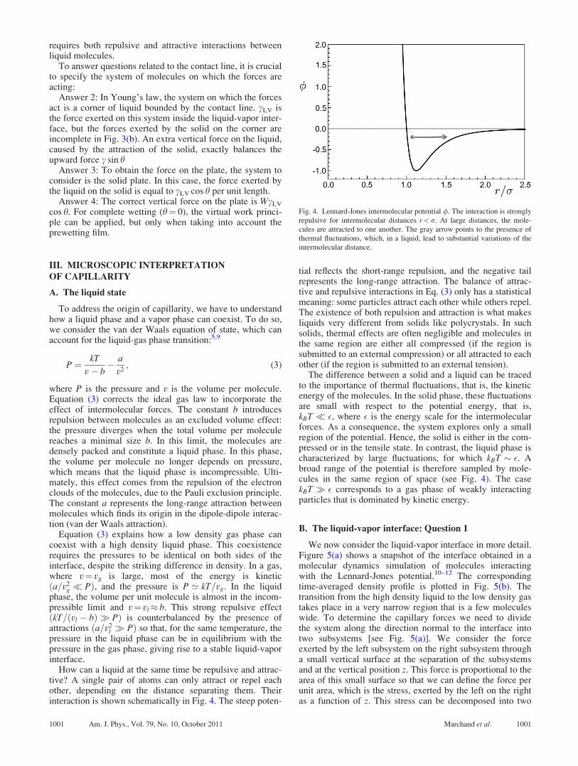
How can a liquid at the same time be repulsive and attrac-tive? A single pair of atoms can only attract or repel eachother, depending on the distance separating them. Theirinteraction is shown schematically in Fig. 4. The steep poten-
tial reflects the short-range repulsion, and the negative tailrepresents the long-range attraction. The balance of attrac-tive and repulsive interactions in Eq. (3) only has a statisticalmeaning: some particles attract each other while others repel.The existence of both repulsion and attraction is what makesliquids very different from solids like polycrystals. In suchsolids, thermal effects are often negligible and molecules inthe same region are either all compressed (if the region issubmitted to an external compression) or all attracted to eachother (if the region is submitted to an external tension).
The difference between a solid and a liquid can be tracedto the importance of thermal fluctuations, that is, the kineticenergy of the molecules. In the solid phase, these fluctuationsare small with respect to the potential energy, that is,kBT � �, where � is the energy scale for the intermolecularforces. As a consequence, the system explores only a smallregion of the potential. Hence, the solid is either in the com-pressed or in the tensile state. In contrast, the liquid phase ischaracterized by large fluctuations, for which kBT � �. Abroad range of the potential is therefore sampled by mole-cules in the same region of space (see Fig. 4). The casekBT � � corresponds to a gas phase of weakly interactingparticles that is dominated by kinetic energy.
B. The liquid-vapor interface: Question 1
We now consider the liquid-vapor interface in more detail.Figure 5(a) shows a snapshot of the interface obtained in amolecular dynamics simulation of molecules interactingwith the Lennard-Jones potential.10–12 The correspondingtime-averaged density profile is plotted in Fig. 5(b). Thetransition from the high density liquid to the low density gastakes place in a very narrow region that is a few moleculeswide. To determine the capillary forces we need to dividethe system along the direction normal to the interface intotwo subsystems [see Fig. 5(a)]. We consider the forceexerted by the left subsystem on the right subsystem througha small vertical surface at the separation of the subsystemsand at the vertical position z. This force is proportional to thearea of this small surface so that we can define the force perunit area, which is the stress, exerted by the left on the rightas a function of z. This stress can be decomposed into two
Fig. 4. Lennard-Jones intermolecular potential /. The interaction is strongly
repulsive for intermolecular distances r<r. At large distances, the mole-
cules are attracted to one another. The gray arrow points to the presence of
thermal fluctuations, which, in a liquid, lead to substantial variations of the
intermolecular distance.
1001 Am. J. Phys., Vol. 79, No. 10, October 2011 Marchand et al. 1001
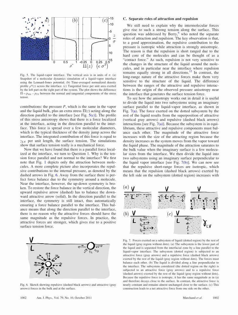
contributions: the pressure P, which is the same in the vaporand the liquid bulk, plus an extra stress P(z) acting along thedirection parallel to the interface [see Fig. 5(c)]. The profileof this stress anisotropy shows that there is a force localizedat the interface, acting in the direction parallel to the inter-face. This force is spread over a few molecular diameters,which is the typical thickness of the density jump across theinterface. The integrated contribution of this force is equal tocLV per unit length, the surface tension. The simulationsshow that surface tension really is a mechanical force.
Now that we have found that there is a parallel force local-ized at the interface, we turn to Question 1. Why is the ten-sion force parallel and not normal to the interface? We firstnote that Fig. 1 depicts only the attraction between mole-cules. A more complete picture also incorporates the repul-sive contributions to the internal pressure, as denoted by thedashed arrows in Fig. 6. Away from the surface there is per-fect force balance due to the symmetry around a molecule.Near the interface, however, the up-down symmetry is bro-ken. To restore the force balance in the vertical direction, theupward repulsive arrow (dashed) has to balance the down-ward attractive arrow (solid). In the direction parallel to theinterface, the symmetry is still intact, thus automaticallyensuring a force balance parallel to the interface. This bal-ance means that along the direction parallel to the interface,there is no reason why the attractive forces should have thesame magnitude as the repulsive forces. In practice, theattractive forces are stronger, which gives rise to a positivesurface tension force.
C. Separate roles of attraction and repulsion
We still need to explain why the intermolecular forcesgive rise to such a strong tension along the surface. Thisquestion was addressed by Berry,6 who noted the separateroles of attraction and repulsion. The key observation is that,to a good approximation, the repulsive contribution to thepressure is isotropic while attraction is strongly anisotropic.The reason is that the repulsion is short ranged due to thehard core of the molecules and can be thought of as a“contact force.” As such, repulsion is not very sensitive tothe changes in the structure of the liquid around the mole-cules, and in particular near the interface where repulsionremains equally strong in all directions.12 In contrast, thelong-range nature of the attractive forces make them verysensitive to the structure of the liquid. The differencebetween the ranges of the attractive and repulsive interac-tions is the origin of the observed pressure anisotropy nearthe interface that generates the surface tension force.
To see how the anisotropy works out in detail it is usefulto divide the liquid into two subsystems using an imaginarysurface parallel to the liquid-vapor interface, as shown inFig. 7(a). The force exerted on the dotted subsystem by therest of the liquid results from the superposition of attractive(vertical gray arrows) and repulsive (dashed black arrows)interactions [see Fig. 7(a)]. Because the subsystem is in equi-librium, these attractive and repulsive components must bal-ance each other. The magnitude of the attractive forceincreases with the size of the attracting region because thedensity increases as the system moves from the vapor towardthe liquid phase. The magnitude of the attraction saturates tothe bulk value when the imaginary surface is a few molecu-lar sizes from the interface. We then divide the liquid intotwo subsystems using an imaginary surface perpendicular tothe liquid vapor interface [see Fig. 7(b)]. We can now seethat the repulsive short-range forces are isotropic, whichmeans that the repulsion (dashed black arrows) exerted bythe left side on the subsystem (dotted region) increases with
Fig. 5. The liquid-vapor interface. The vertical axis is in units of r. (a)
Snapshot of a molecular dynamics simulation of a liquid-vapor interface
using the Lennard-Jones potential. (b) Time-averaged normalized density
profile q*(z) across the interface. (c) Tangential force per unit area exerted
by the left part on the right part of the system. The plot shows the difference
P¼ pNN – pTT between the normal and tangential components of the stress
tensor.
Fig. 6. Sketch showing repulsive (dashed black arrows) and attractive (gray
arrows) forces in the bulk and at the surface.
Fig. 7. Forces exerted on a subsystem of liquid (dotted region) by the rest of
the liquid (gray region without dots). (a) The subsystem is the lower part of
the liquid and is separated from the interfacial zone by a line parallel to the
liquid-vapor interface. The subsystem (dotted region) is subjected to an
attractive force (gray arrows) and a repulsive force (dashed black arrows)
exerted by the rest of the liquid (gray region without dots). The forces must
balance each other. (b) The liquid is divided along a line perpendicular to
the interface. The subsystem considered (the dotted region on the right) is
subjected to an attractive force (gray arrows) and to a repulsive force
(dashed arrows) exerted by the rest of the liquid (gray region without dots).
Because the repulsive force is isotropic, it has the same magnitude as in (a)
and therefore decays close to the surface. In contrast, the attractive force is
nearly constant and remains almost unchanged close to the surface. (c) This
construction leads to a net attractive force from one side on the other.
1002 Am. J. Phys., Vol. 79, No. 10, October 2011 Marchand et al. 1002
depth in a way analogous to that in Fig. 7(a). In contrast, thestrength of the attraction has a much weaker dependence ondepth; for simplicity, we draw it with a constant magnitudewhich equals the attraction in the bulk. As a result, there is anet attraction of the subsystem by the rest of the liquid [seethe dark gray arrow in Fig. 7(c)].
D. The liquid-solid interface
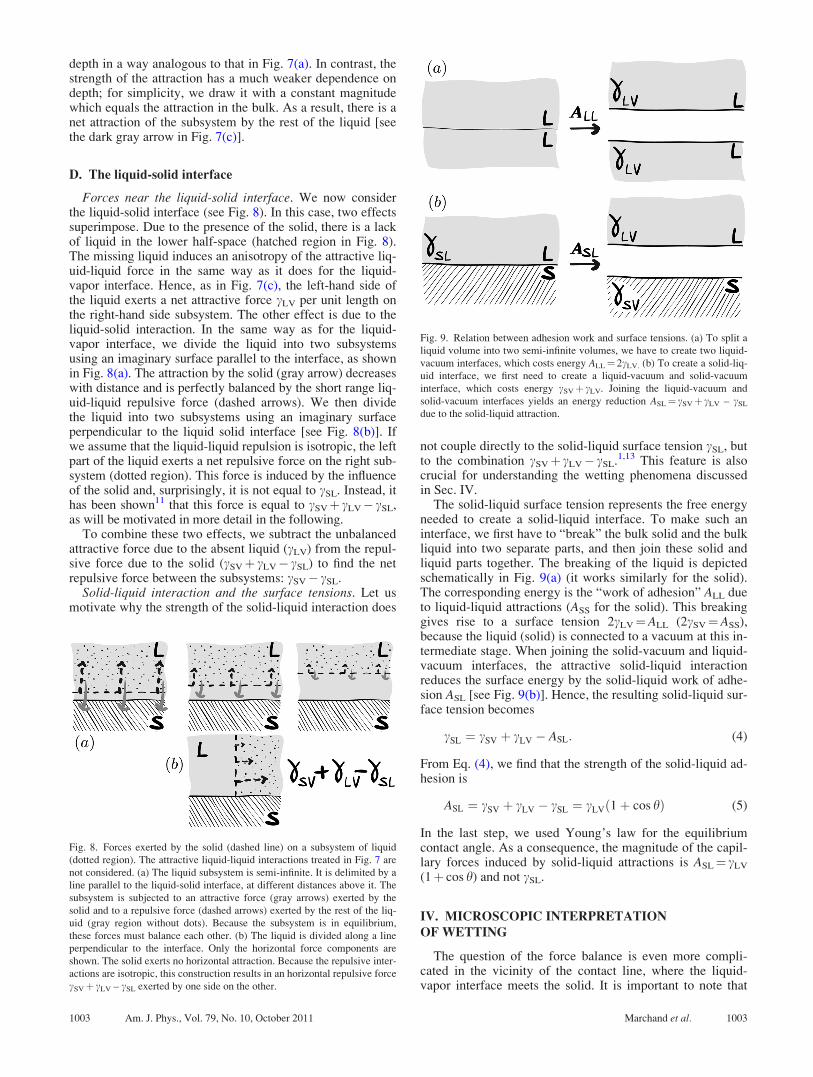
Forces near the liquid-solid interface. We now considerthe liquid-solid interface (see Fig. 8). In this case, two effectssuperimpose. Due to the presence of the solid, there is a lackof liquid in the lower half-space (hatched region in Fig. 8).The missing liquid induces an anisotropy of the attractive liq-uid-liquid force in the same way as it does for the liquid-vapor interface. Hence, as in Fig. 7(c), the left-hand side ofthe liquid exerts a net attractive force cLV per unit length onthe right-hand side subsystem. The other effect is due to theliquid-solid interaction. In the same way as for the liquid-vapor interface, we divide the liquid into two subsystemsusing an imaginary surface parallel to the interface, as shownin Fig. 8(a). The attraction by the solid (gray arrow) decreaseswith distance and is perfectly balanced by the short range liq-uid-liquid repulsive force (dashed arrows). We then dividethe liquid into two subsystems using an imaginary surfaceperpendicular to the liquid solid interface [see Fig. 8(b)]. Ifwe assume that the liquid-liquid repulsion is isotropic, the leftpart of the liquid exerts a net repulsive force on the right sub-system (dotted region). This force is induced by the influenceof the solid and, surprisingly, it is not equal to cSL. Instead, ithas been shown11 that this force is equal to cSVþ cLV� cSL,as will be motivated in more detail in the following.
To combine these two effects, we subtract the unbalancedattractive force due to the absent liquid (cLV) from the repul-sive force due to the solid (cSVþ cLV� cSL) to find the netrepulsive force between the subsystems: cSV� cSL.
Solid-liquid interaction and the surface tensions. Let usmotivate why the strength of the solid-liquid interaction does
not couple directly to the solid-liquid surface tension cSL, butto the combination cSVþ cLV� cSL.1,13 This feature is alsocrucial for understanding the wetting phenomena discussedin Sec. IV.
The solid-liquid surface tension represents the free energyneeded to create a solid-liquid interface. To make such aninterface, we first have to “break” the bulk solid and the bulkliquid into two separate parts, and then join these solid andliquid parts together. The breaking of the liquid is depictedschematically in Fig. 9(a) (it works similarly for the solid).The corresponding energy is the “work of adhesion” ALL dueto liquid-liquid attractions (ASS for the solid). This breakinggives rise to a surface tension 2cLV¼ALL (2cSV¼ASS),because the liquid (solid) is connected to a vacuum at this in-termediate stage. When joining the solid-vacuum and liquid-vacuum interfaces, the attractive solid-liquid interactionreduces the surface energy by the solid-liquid work of adhe-sion ASL [see Fig. 9(b)]. Hence, the resulting solid-liquid sur-face tension becomes
cSL ¼ cSV þ cLV � ASL: (4)
From Eq. (4), we find that the strength of the solid-liquid ad-hesion is
ASL ¼ cSV þ cLV � cSL ¼ cLVð1þ cos hÞ (5)
In the last step, we used Young’s law for the equilibriumcontact angle. As a consequence, the magnitude of the capil-lary forces induced by solid-liquid attractions is ASL¼ cLV
(1þ cos h) and not cSL.
IV. MICROSCOPIC INTERPRETATION
OF WETTING
The question of the force balance is even more compli-cated in the vicinity of the contact line, where the liquid-vapor interface meets the solid. It is important to note that
Fig. 8. Forces exerted by the solid (dashed line) on a subsystem of liquid
(dotted region). The attractive liquid-liquid interactions treated in Fig. 7 are
not considered. (a) The liquid subsystem is semi-infinite. It is delimited by a
line parallel to the liquid-solid interface, at different distances above it. The
subsystem is subjected to an attractive force (gray arrows) exerted by the
solid and to a repulsive force (dashed arrows) exerted by the rest of the liq-
uid (gray region without dots). Because the subsystem is in equilibrium,
these forces must balance each other. (b) The liquid is divided along a line
perpendicular to the interface. Only the horizontal force components are
shown. The solid exerts no horizontal attraction. Because the repulsive inter-
actions are isotropic, this construction results in an horizontal repulsive force
cSVþ cLV – cSL exerted by one side on the other.
Fig. 9. Relation between adhesion work and surface tensions. (a) To split a
liquid volume into two semi-infinite volumes, we have to create two liquid-
vacuum interfaces, which costs energy ALL¼ 2cLV. (b) To create a solid-liq-
uid interface, we first need to create a liquid-vacuum and solid-vacuum
interface, which costs energy cSVþ cLV. Joining the liquid-vacuum and
solid-vacuum interfaces yields an energy reduction ASL¼ cSVþ cLV – cSL
due to the solid-liquid attraction.
1003 Am. J. Phys., Vol. 79, No. 10, October 2011 Marchand et al. 1003
the contact line does not represent any material. Instead it isan imaginary line that marks the separation between wettedand dry parts of the solid. The question “What is the force onthe contact line?” is thus ill-posed, because there are no mol-ecules on which such a force would act. Only a collection ofmatter can be submitted to a force. Therefore, care should betaken to properly define the systems that play a role near thecontact line, which are the liquid near the contact line andthe solid underneath it. In the following, we will show how acareful consideration of all the forces on the appropriate ma-terial systems leads to proper force balances, consistent withthe thermodynamic predictions.
All results and sketches provided in this section, some ofwhich may appear counterintuitive, are consistent with adensity functional theory for microscopic interactions14,15
and molecular dynamics simulations.12
A. Force on a liquid corner: Question 2
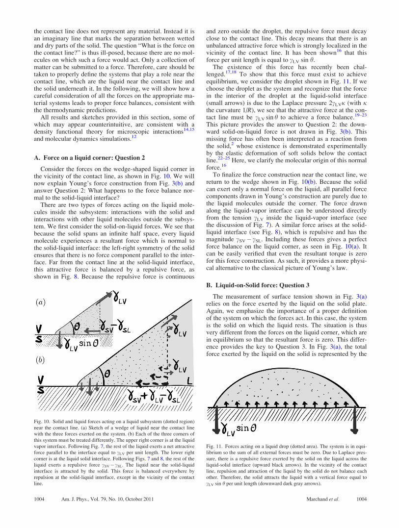
Consider the forces on the wedge-shaped liquid corner inthe vicinity of the contact line, as shown in Fig. 10. We willnow explain Young’s force construction from Fig. 3(b) andanswer Question 2: What happens to the force balance nor-mal to the solid-liquid interface?
There are two types of forces acting on the liquid mole-cules inside the subsystem: interactions with the solid andinteractions with other liquid molecules outside the subsys-tem. We first consider the solid-on-liquid forces. We see thatbecause the solid spans an infinite half space, every liquidmolecule experiences a resultant force which is normal tothe solid-liquid interface: the left-right symmetry of the solidensures that there is no force component parallel to the inter-face. Far from the contact line at the solid-liquid interface,this attractive force is balanced by a repulsive force, asshown in Fig. 8. Because the repulsive force is continuous
and zero outside the droplet, the repulsive force must decayclose to the contact line. This decay means that there is anunbalanced attractive force which is strongly localized in thevicinity of the contact line. It has been shown16 that thisforce per unit length is equal to cLV sin h.
The existence of this force has recently been chal-lenged.17,18 To show that this force must exist to achieveequilibrium, we consider the droplet shown in Fig. 11. If wechoose the droplet as the system and recognize that the forcein the interior of the droplet at the liquid-solid interface(small arrows) is due to the Laplace pressure 2cLVj (with jthe curvature 1/R), we see that the attractive force at the con-tact line must be cLV sin h to achieve a force balance.19–23
This picture provides the answer to Question 2: the down-ward solid-on-liquid force is not drawn in Fig. 3(b). Thismissing force has often been interpreted as a reaction fromthe solid,2 whose existence is demonstrated experimentallyby the elastic deformation of soft solids below the contactline.22–25 Here, we clarify the molecular origin of this normalforce.16
To finalize the force construction near the contact line, wereturn to the wedge shown in Fig. 10(b). Because the solidcan exert only a normal force on the liquid, all parallel forcecomponents drawn in Young’s construction are purely due tothe liquid molecules outside the corner. The force drawnalong the liquid-vapor interface can be understood directlyfrom the tension cLV inside the liquid-vapor interface (seethe discussion of Fig. 7). A similar force arises at the solid-liquid interface (see Fig. 8), which is repulsive and has themagnitude cSV� cSL. Including these forces gives a perfectforce balance on the liquid corner, as seen in Fig. 10(a). Itcan be easily verified that even the resultant torque is zerofor this force construction. As such, it provides a more physi-cal alternative to the classical picture of Young’s law.
B. Liquid-on-Solid force: Question 3
The measurement of surface tension shown in Fig. 3(a)relies on the force exerted by the liquid on the solid plate.Again, we emphasize the importance of a proper definitionof the system on which the forces act. In this case, the systemis the solid on which the liquid rests. The situation is thusvery different from the forces on the liquid corner, which arein equilibrium so that the resultant force is zero. This differ-ence provides the key to Question 3. In Fig. 3(a), the totalforce exerted by the liquid on the solid is represented by the
Fig. 10. Solid and liquid forces acting on a liquid subsystem (dotted region)
near the contact line. (a) Sketch of a wedge of liquid near the contact line
with the three forces exerted on the system. (b) Each of the three corners of
this system must be treated differently. The upper right corner is at the liquid
vapor interface. Following Fig. 7, the rest of the liquid exerts a net attractive
force parallel to the interface equal to cLV per unit length. The lower right
corner is at the liquid solid interface. Following Figs. 7 and 8, the rest of the
liquid exerts a repulsive force cSV� cSL. The liquid near the solid-liquid
interface is attracted by the solid. This force is balanced everywhere by
repulsion at the solid-liquid interface, except in the vicinity of the contact
line.
Fig. 11. Forces acting on a liquid drop (dotted area). The system is in equi-
librium so the sum of all external forces must be zero. Due to Laplace pres-
sure, there is a repulsive force exerted by the solid on the liquid across the
liquid-solid interface (upward black arrows). In the vicinity of the contact
line, repulsion and attraction of the liquid by the solid do not balance each
other. Therefore, the solid attracts the liquid with a vertical force equal to
cLV sin h per unit length (downward dark gray arrows).
1004 Am. J. Phys., Vol. 79, No. 10, October 2011 Marchand et al. 1004

resultant ~cLV, and Fig. 3(b) represents the balance of theforces acting on the liquid wedge.
Forces near the contact line. We turn again to the micro-scopic description of the forces in the vicinity of the contactline. It turns out that the normal component of the forceexerted on the solid is equal to cLV sin h, consistent with themacroscopic picture of a tension force pulling along the liq-uid-vapor interface. The parallel component of the liquid-on-solid force does not have the expected magnitude cLV cos h,but cLVþ cSV� cSL¼ cLV(1þ cos h). This unexpected mag-nitude can be understood as follows. Figure 12(a) illustratesthat the tangential force component originates from the long-range attraction between solid and liquid molecules. We pre-viously demonstrated that the strength of this solid-liquid ad-hesion is ASL¼ cLV (1þ cos h). Hence, there is no reasonwhy the total force on the solid should be cLV cos h. A den-sity functional theory calculation confirms a tangential liq-uid-on-solid force of magnitude ASL¼ cLV(1þ cos h).16
The physics of this surprising result is illustrated by Fig.12. The macroscopic intuition that the resultant surface ten-sion force pulls along the liquid-vapor interface would pre-dict a force to the left whenever the contact angle h> 90�.However, it is clear from the sketch of the attractive forcesthat the sum of all the parallel components must be orientedtoward the liquid (right side in the figure). This orientationstems from the asymmetry between the amount of liquidattracting the solid molecules on both sides of the contactline: there are always more liquid molecules on the right sideof the contact line in Fig. 12. This behavior is consistentwith the parallel force cLV(1þ cos h), but not with a forcecLV cos h (which changes sign at h¼ 90�). Note that whenconsidering the force exerted by the solid on the liquid, thisasymmetry does not occur because the solid is left-right sym-
metric, and therefore there is no tangential component. Thisdifference between the forces acting on the solid or on theliquid again illustrates that a detailed force interpretationcrucially relies on the definition of the system.
Global force balance: curvature of solid-liquid interface.To solve the apparent discrepancy between the tangentialforce cLV(1þ cos h) and the thermodynamic result we dis-cussed in Sec. II B, which was consistent with a tangentialforce cLV cos h, we have to consider all the forces exerted bythe liquid on the solid, not just the forces near the contactline. The key point is that the submerged solid bodies cannotbe flat everywhere and the liquid-solid interface must becurved. If the interface separating the solid from the liquid isflat, the net normal force is locally zero because repulsion bal-ances attraction (far away from the contact line). When theinterface is curved, the repulsive force inside the liquid isenhanced due to the curvature, in a way similar to the Laplacepressure. As shown in Fig. 13, the presence of a curved half-space of liquid acts on the solid and creates an unbalancedliquid-on-solid force cLVj per unit area. Density functionaltheory calculations16 show that the resultant pressure couplesonly to cLV and not to cSL. As we will show, this supplemen-tary force is exactly what is needed to restore consistencybetween the microscopic and thermodynamic forces.
An excellent demonstration of this effect is the longdebated case of a “floating-pin” under zero gravity, as shownin Fig 14. Although a floating pin in a system with gravityleaves a visible depression in the liquid-vapor interface nearthe contact line [see Fig. 14(e)], the zero-gravity conditionensures that the interface has constant curvature, that is, it isstraight everywhere. Because the liquid-vapor interface isflat, the vertical position of the pin depends on the equilib-rium contact-angle alone and not on the density ratio of thematerials involved. As shown in Fig. 12, the liquid-on-solidforces near the contact lines are not oriented along the liq-uid-vapor interface, but point toward the interior of the
Fig. 12. Forces acting on the solid subsystem (hatched areas) by the liquid
(gray areas) near the contact line. (a) Distribution of forces acting on the
solid near the contact line. Due to the attraction of the liquid, the solid is
attracted toward the liquid (solid gray arrows). The absence of liquid on the
left part of the contact line ensures the tangential force is toward the liquid,
even for h> 90�. The repulsion (dotted arrows) arises from the contact force
at the solid-liquid interface. Far from the contact line, repulsion and attrac-
tion balance each other. (b) The resultant force acting on the solid near the
contact line. The net normal force is cLV sin h, and the parallel force
cLVþ cSV� cSL¼ cLV (1þ cos h).
Fig. 13. Forces acting on a solid at the solid-liquid interface. (a) Without
liquid, there is neither repulsion nor attraction. (b) When liquid is present
there is repulsion and attraction. However, the repulsion is not completely
balanced at this curved interface, because there is more liquid in this geome-
try than in a plane geometry. (c) The resulting force is analogous to the force
created by the Laplace pressure at liquid-vapor interfaces. This force is cLVjper unit surface, where j> 0 is the curvature of the liquid. This expression
only shows a dependence on the liquid-liquid interactions because the curva-
ture has an effect only through the missing liquid matter.
1005 Am. J. Phys., Vol. 79, No. 10, October 2011 Marchand et al. 1005
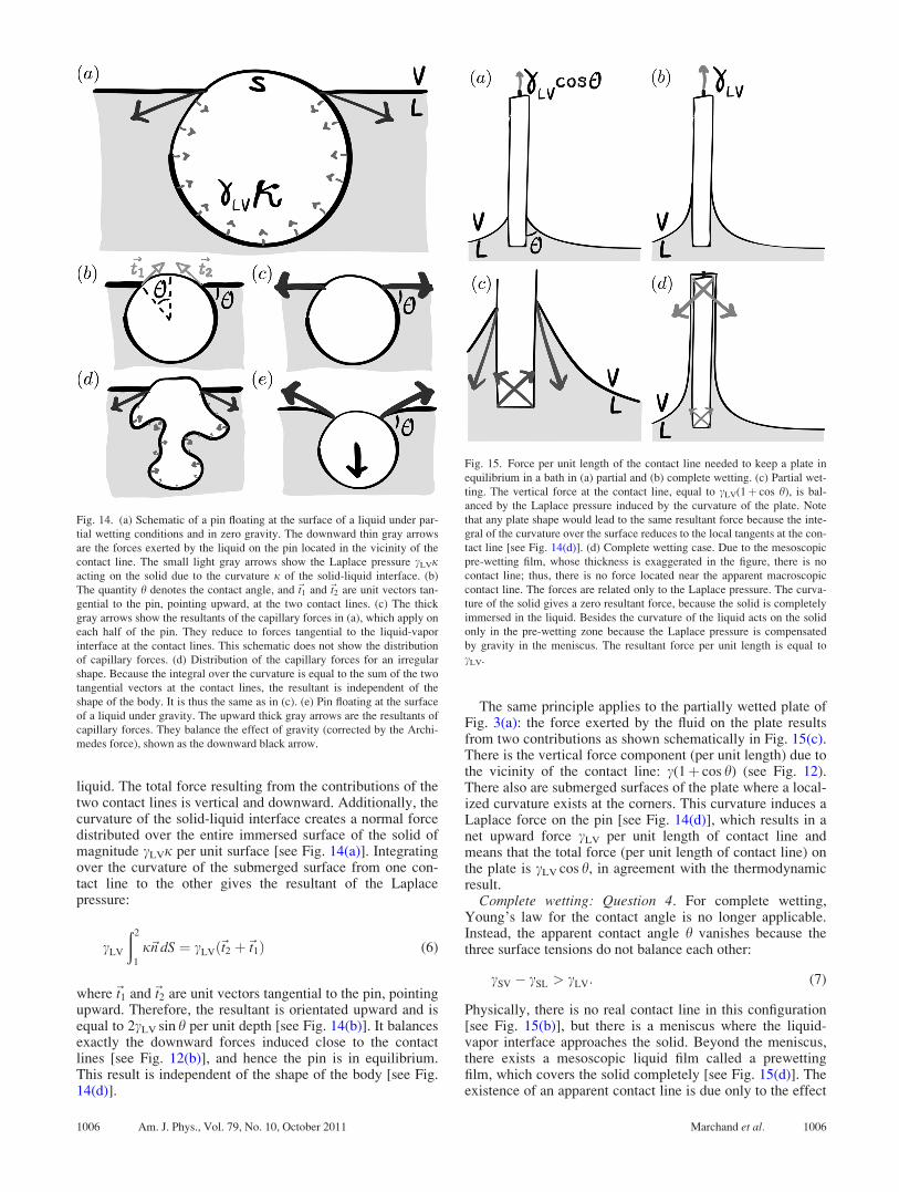
liquid. The total force resulting from the contributions of thetwo contact lines is vertical and downward. Additionally, thecurvature of the solid-liquid interface creates a normal forcedistributed over the entire immersed surface of the solid ofmagnitude cLVj per unit surface [see Fig. 14(a)]. Integratingover the curvature of the submerged surface from one con-tact line to the other gives the resultant of the Laplacepressure:
cLV
ð2
1
j~n dS ¼ cLVð~t2 þ~t1Þ (6)
where~t1 and~t2 are unit vectors tangential to the pin, pointingupward. Therefore, the resultant is orientated upward and isequal to 2cLV sin h per unit depth [see Fig. 14(b)]. It balancesexactly the downward forces induced close to the contactlines [see Fig. 12(b)], and hence the pin is in equilibrium.This result is independent of the shape of the body [see Fig.14(d)].
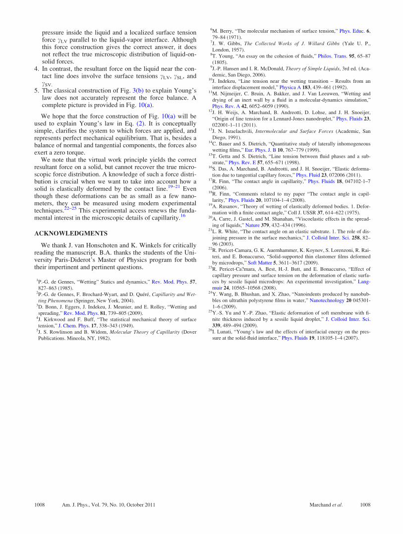
The same principle applies to the partially wetted plate ofFig. 3(a): the force exerted by the fluid on the plate resultsfrom two contributions as shown schematically in Fig. 15(c).There is the vertical force component (per unit length) due tothe vicinity of the contact line: c(1þ cos h) (see Fig. 12).There also are submerged surfaces of the plate where a local-ized curvature exists at the corners. This curvature induces aLaplace force on the pin [see Fig. 14(d)], which results in anet upward force cLV per unit length of contact line andmeans that the total force (per unit length of contact line) onthe plate is cLV cos h, in agreement with the thermodynamicresult.
Complete wetting: Question 4. For complete wetting,Young’s law for the contact angle is no longer applicable.Instead, the apparent contact angle h vanishes because thethree surface tensions do not balance each other:
cSV � cSL > cLV: (7)
Physically, there is no real contact line in this configuration[see Fig. 15(b)], but there is a meniscus where the liquid-vapor interface approaches the solid. Beyond the meniscus,there exists a mesoscopic liquid film called a prewettingfilm, which covers the solid completely [see Fig. 15(d)]. Theexistence of an apparent contact line is due only to the effect
Fig. 14. (a) Schematic of a pin floating at the surface of a liquid under par-
tial wetting conditions and in zero gravity. The downward thin gray arrows
are the forces exerted by the liquid on the pin located in the vicinity of the
contact line. The small light gray arrows show the Laplace pressure cLVjacting on the solid due to the curvature j of the solid-liquid interface. (b)
The quantity h denotes the contact angle, and~t1 and~t2 are unit vectors tan-
gential to the pin, pointing upward, at the two contact lines. (c) The thick
gray arrows show the resultants of the capillary forces in (a), which apply on
each half of the pin. They reduce to forces tangential to the liquid-vapor
interface at the contact lines. This schematic does not show the distribution
of capillary forces. (d) Distribution of the capillary forces for an irregular
shape. Because the integral over the curvature is equal to the sum of the two
tangential vectors at the contact lines, the resultant is independent of the
shape of the body. It is thus the same as in (c). (e) Pin floating at the surface
of a liquid under gravity. The upward thick gray arrows are the resultants of
capillary forces. They balance the effect of gravity (corrected by the Archi-
medes force), shown as the downward black arrow.
Fig. 15. Force per unit length of the contact line needed to keep a plate in
equilibrium in a bath in (a) partial and (b) complete wetting. (c) Partial wet-
ting. The vertical force at the contact line, equal to cLV(1þ cos h), is bal-
anced by the Laplace pressure induced by the curvature of the plate. Note
that any plate shape would lead to the same resultant force because the inte-
gral of the curvature over the surface reduces to the local tangents at the con-
tact line [see Fig. 14(d)]. (d) Complete wetting case. Due to the mesoscopic
pre-wetting film, whose thickness is exaggerated in the figure, there is no
contact line; thus, there is no force located near the apparent macroscopic
contact line. The forces are related only to the Laplace pressure. The curva-
ture of the solid gives a zero resultant force, because the solid is completely
immersed in the liquid. Besides the curvature of the liquid acts on the solid
only in the pre-wetting zone because the Laplace pressure is compensated
by gravity in the meniscus. The resultant force per unit length is equal to
cLV.
1006 Am. J. Phys., Vol. 79, No. 10, October 2011 Marchand et al. 1006

of gravity: on a flat surface, the liquid would simply spread.The interface between the liquid and vapor phases conse-quently has two regions. In the lower region, the meniscuscan be described by the balance between the Laplace pres-sure and the hydrostatic pressure
cLVj ¼ qgz; (8)
where z is the height above the bath (thus, no additional con-stant is needed) and j is the curvature of the interface. If weintroduce the capillary length ‘c ¼
ffiffiffiffiffiffiffiffiffiffiffiffiffiffifficLV=qg
p, Eq. (8) can be
written as ‘2cj ¼ z. In the upper region, there is the prewet-
ting film whose thickness h(z) is determined by the balancebetween the gravitational potential and the disjoining pres-sure P(h) defined as the potential energy per unit volume atthe surface of a liquid layer of thickness h. It describes theattraction of the solid in the layer of liquid. Therefore, thebalance is1,13
PðhÞ ¼ qgz: (9)
Because the prewetting film is flat, the contribution of theLaplace pressure can be neglected (j¼ 0) in this regime.The pressure scales as
PðhÞ ’ cSV � cSL � cLVð Þr2
h3; (10)
for films where h� r, r is a length on the order of the mo-lecular size. The pressure vanishes in the limiting casecSV¼ cSLþ cLV, which can be interpreted as the situation forwhich the interaction is the same with the liquid and with thesolid. Then, we do not expect any influence of the thicknessh on the energy.
We equate gravity and the disjoining pressure, Eq. (9),and obtain the thickness profile in the prewetting region:
hðzÞ ’ cSV � cSL � cLVð Þr2
qgz
� �1=3
: (11)
In the vicinity of the apparent contact line, where the twozones must match, the thickness is thus of order l
1=3c r2=3.
Because lc is the order of millimeters and r is the order ofnanometers. From the microscopic point of view, the solid iscompletely surrounded by a semi-infinite layer of liquidh� rð Þ. Therefore, the only forces acting on a solid in com-
plete wetting are normal contact forces, such as Laplacepressures. There are no contact line forces such as thosedescribed in Fig. 12(b).
The forces exerted by the liquid on the solid are related tothe curvature of the liquid-solid interface and inside the pre-wetting film to the curvature of the liquid-vapor interface[see Fig 15(d)]. If integrated over the whole submergedsolid, the curvature of the solid gives a zero resultant force,whereas the curvature of the liquid is integrated only wherethe prewetting film exists. As a result, the resultant force isvertical and has an amplitude cLV per unit length of the appa-rent contact line.
This result is consistent with the thermodynamic perspec-tive. Because the solid is covered by a liquid layer muchthicker than the molecular size, the surface tension above theapparent contact line is not cSV but is cSLþ cLV, because theplate is always completely submerged. In essence, this cov-erage means that the plate never leaves the liquid bath when
the plate is pulled upward. When moving, there is no changeof the solid-vapor interface area (it remains zero) or of thesolid-liquid interface area (which is the total area of theplate). The only change occurs at the liquid-vapor interfacearea, which is increased, and the required pulling strength isthus cLV per unit length of the apparent contact line.
V. SUMMARY
We have raised simple questions about capillarity thatmany students face. By studying the interfaces from a micro-scopic perspective, we have provided answers to these ques-tions, and reconciled thermodynamics and statistical physics.
We have provided a mechanical perspective about whythere exists an attractive force parallel to interfaces, which iscalled the surface tension. The absence of liquid above theliquid-vapor interface creates an attractive anisotropic forcewithin a few molecular lengths from the interface, whereasthe repulsion remains isotropic and scales with the local den-sity of the fluid. The attractive anisotropy leads to a stronglocalized force parallel to the interface called the surface ten-sion. This anisotropy and corresponding tangential forceoccurs at liquid-solid interfaces as well, where there is also ahalf-space of liquid missing.
The problems that occur when constructing force picturesat interfaces often arise from an improper definition of thesystem on which the forces act. By considering a corner ofliquid near the contact line as a system, we proposed an alter-native to Young’s construction [see Fig. 3(b)]. The analysislets us locate and understand the different forces, in particu-lar, the attractive force exerted by the solid. This new forceconstruction leads to perfect mechanical equilibrium, wherethe net force and the torque balance.
When looking at the force that is exerted by the liquid onthe solid near the contact line we find that this force is notcLV cos h, but is cLV(1þ cos h). Moreover, a normal stress isexerted in all the regions of any curved solid-liquid interface,so that the liquid pulls the solid when the latter is convex.This force is equivalent to the usual Laplace pressure. Wehave to take both these forces into account to obtain the netforce from thermodynamics. The advantage of this micro-scopic force description is that it provides a simple answer toa problem that has been controversial: the floating pinparadox.17,18,26
The drawings and several relations in this article are basedon results obtained using density functional theory in thesharp-kink approximation.16 This model can be used to makequantitative predictions of the force distributions in the liq-uid and in the solid.
We realize that a detailed picture of the microscopic forcesis not necessarily the most accessible for teaching purposes. Inparticular, when introducing the basic concepts of capillarity,it is much simpler to work from the thermodynamic perspec-tive: energy minimization naturally yields the equilibriumconditions, and the resultant forces can be calculated from thevirtual work principle. Nevertheless, our analysis provides anumber of insights that are useful when teaching capillarity:
1. To determine the capillary forces it is crucial to explicitlyspecify the system (a specific collection of matter) towhich the forces are applied.
2. The surface tensions cSL and cSV do not pull on the solid.3. The global force exerted on the solid by the liquid can be
calculated by adding the contributions of the Laplace
1007 Am. J. Phys., Vol. 79, No. 10, October 2011 Marchand et al. 1007
pressure inside the liquid and a localized surface tensionforce cLV parallel to the liquid-vapor interface. Althoughthis force construction gives the correct answer, it doesnot reflect the true microscopic distribution of liquid-on-solid forces.
4. In contrast, the resultant force on the liquid near the con-tact line does involve the surface tensions cLV, cSL, andcSV.
5. The classical construction of Fig. 3(b) to explain Young’slaw does not accurately represent the force balance. Acomplete picture is provided in Fig. 10(a).
We hope that the force construction of Fig. 10(a) will beused to explain Young’s law in Eq. (2). It is conceptuallysimple, clarifies the system to which forces are applied, andrepresents perfect mechanical equilibrium. That is, besides abalance of normal and tangential components, the forces alsoexert a zero torque.
We note that the virtual work principle yields the correctresultant force on a solid, but cannot recover the true micro-scopic force distribution. A knowledge of such a force distri-bution is crucial when we want to take into account how asolid is elastically deformed by the contact line.19–21 Eventhough these deformations can be as small as a few nano-meters, they can be measured using modern experimentaltechniques.22–25 This experimental access renews the funda-mental interest in the microscopic details of capillarity.16
ACKNOWLEDGMENTS
We thank J. van Honschoten and K. Winkels for criticallyreading the manuscript. B.A. thanks the students of the Uni-versity Paris-Diderot’s Master of Physics program for boththeir impertinent and pertinent questions.
1P.-G. de Gennes, “Wetting” Statics and dynamics,” Rev. Mod. Phys. 57,
827–863 (1985).2P.-G. de Gennes, F. Brochard-Wyart, and D. Quere, Capillarity and Wet-ting Phenomena (Springer, New York, 2004).
3D. Bonn, J. Eggers, J. Indekeu, J. Meunier, and E. Rolley, “Wetting and
spreading,” Rev. Mod. Phys. 81, 739–805 (2009).4J. Kirkwood and F. Buff, “The statistical mechanical theory of surface
tension,” J. Chem. Phys. 17, 338–343 (1949).5J. S. Rowlinson and B. Widom, Molecular Theory of Capillarity (Dover
Publications. Mineola, NY, 1982).
6M. Berry, “The molecular mechanism of surface tension,” Phys. Educ. 6,
79–84 (1971).7J. W. Gibbs, The Collected Works of J. Willard Gibbs (Yale U. P.,
London, 1957).8T. Young, “An essay on the cohesion of fluids,” Philos. Trans. 95, 65–87
(1805).9J.-P. Hansen and I. R. McDonald, Theory of Simple Liquids, 3rd ed. (Aca-
demic, San Diego, 2006).10J. Indekeu, “Line tension near the wetting transition – Results from an
interface displacement model,” Physica A 183, 439–461 (1992).11M. Nijmeijer, C. Bruin, A. Bakker, and J. Van Leeuwen, “Wetting and
drying of an inert wall by a fluid in a molecular-dynamics simulation,”
Phys. Rev. A 42, 6052–6059 (1990).12J. H. Weijs, A. Marchand, B. Andreotti, D. Lohse, and J. H. Snoeijer,
“Origin of line tension for a Lennard-Jones nanodroplet,” Phys. Fluids 23,
022001-1–11 (2011).13J. N. Israelachvili, Intermolecular and Surface Forces (Academic, San
Diego, 1991).14C. Bauer and S. Dietrich, “Quantitative study of laterally inhomogeneous
wetting films,” Eur. Phys. J. B 10, 767–779 (1999).15T. Getta and S. Dietrich, “Line tension between fluid phases and a sub-
strate,” Phys. Rev. E 57, 655–671 (1998).16S. Das, A. Marchand, B. Andreotti, and J. H. Snoeijer, “Elastic deforma-
tion due to tangential capillary forces,” Phys. Fluid 23, 072006 (2011).17R. Finn, “The contact angle in capillarity,” Phys. Fluids 18, 047102-1–7
(2006).18R. Finn, “Comments related to my paper “The contact angle in capil-
larity,” Phys. Fluids 20, 107104-1–4 (2008).19A. Rusanov, “Theory of wetting of elastically deformed bodies. 1. Defor-
mation with a finite contact angle,” Coll J. USSR 37, 614–622 (1975).20A. Carre, J. Gastel, and M. Shanahan, “Viscoelastic effects in the spread-
ing of liquids,” Nature 379, 432–434 (1996).21L. R. White, “The contact angle on an elastic substrate. 1. The role of dis-
joining pressure in the surface mechanics,” J. Colloid Inter. Sci. 258, 82–
96 (2003).22R. Pericet-Camara, G. K. Auernhammer, K. Koynov, S. Lorenzoni, R. Rai-
teri, and E. Bonaccurso, “Solid-supported thin elastomer films deformed
by microdrops,” Soft Matter 5, 3611–3617 (2009).23R. Pericet-Ca?mara, A. Best, H.-J. Butt, and E. Bonaccurso, “Effect of
capillary pressure and surface tension on the deformation of elastic surfa-
ces by sessile liquid microdrops: An experimental investigation,” Lang-
muir 24, 10565–10568 (2008).24Y. Wang, B. Bhushan, and X. Zhao, “Nanoindents produced by nanobub-
bles on ultrathin polystyrene films in water,” Nanotechnology 20 045301-
1–6 (2009).25Y.-S. Yu and Y.-P. Zhao, “Elastic deformation of soft membrane with fi-
nite thickness induced by a sessile liquid droplet,” J. Colloid Inter. Sci.
339, 489–494 (2009).26I. Lunati, “Young’s law and the effects of interfacial energy on the pres-
sure at the solid-fluid interface,” Phys. Fluids 19, 118105-1–4 (2007).
1008 Am. J. Phys., Vol. 79, No. 10, October 2011 Marchand et al. 1008