Embed Size (px)
Citation preview
Why VNWA2 and VNWA3 does not show correct attenuation of high and low pass filters
or what limitation exist for the VNWA design compared to a professional R&S or HP VNA
Preface:
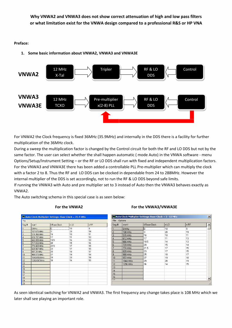
1. Some basic information about VNWA2, VNWA3 and VNWA3E
VNWA2
VNWA3
VNWA3E
For VNWA2 the Clock frequency is fixed 36MHz (35.9MHz) and internally in the DDS there is a facility for further
multiplication of the 36MHz clock.
During a sweep the multiplication factor is changed by the Control circuit for both the RF and LO DDS but not by the
same factor. The user can select whether the shall happen automatic ( mode Auto) in the VNWA software - menu
Options/Setup/Instrument Setting – or the RF or LO DDS shall run with fixed and independent multiplication factors.
For the VNWA3 and VNWA3E there has been added a controllable PLL Pre-multiplier which can multiply the clock
with a factor 2 to 8. Thus the RF and LO DDS can be clocked in dependable from 24 to 288MHz. However the
internal multiplier of the DDS is set accordingly, not to run the RF & LO DDS beyond safe limits.
If running the VNWA3 with Auto and pre multiplier set to 3 instead of Auto then the VNWA3 behaves exactly as
VNWA2.
The Auto switching schema in this special case is as seen below:
For the VNWA2 For the VNWA3/VNWA3E
As seen identical switching for VNWA2 and VNWA3. The first frequency any change takes place is 108 MHz which we
later shall see playing an important role.
12 MHz
X-Tal
RF & LO
DDS
Tripler
12 MHz
TCXO
Pre-multiplier
x(2-8) PLL
RF & LO
DDS
Control
Control
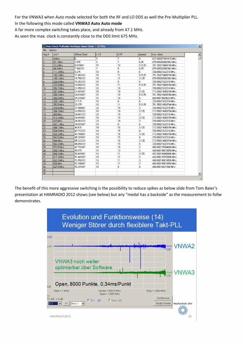
For the VNWA3 when Auto mode selected for both the RF and LO DDS as well the Pre-Multiplier PLL.
In the following this mode called VNWA3 Auto Auto mode
A far more complex switching takes place, and already from 47.1 MHz.
As seen the max. clock is constantly close to the DDS limit 675 MHz.
The benefit of this more aggressive switching is the possibility to reduce spikes as below slide from Tom Baier’s
presentation at HAMRADIO 2012 shows (see below) but any “medal has a backside” as the measurement to follw
demonstrates.
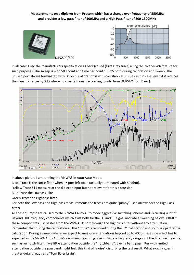
Measurements on a diplexer from Procom which has a change over frequency of 550MHz
and provides a low pass filter of 500MHz and a High Pass filter of 800-1300MHz
DIPX500/800
In all cases I use the manufacturers specification as background (light Gray trace) using the nice VNWA feature for
such purposes. The sweep is with 500 point and time per point 100mS both during calibration and sweep. The
unused port always terminated with 50 ohm. Calibration is with crosstalk cal. in use (just in case) even if it reduces
the dynamic range by 3dB where no crosstalk exist (according to info from DG8SAQ Tom Baier).
In above picture I am running the VNWA3 in Auto Auto Mode.
Black Trace is the Noise floor when RX port left open (actually terminated with 50 ohm).
Yellow Trace S11 measure at the diplexer input but not relevant for this discussion
Blue Trace the Lowpass Filte
Green Trace the Highpass filter.
For both the Low pass and High pass measurements the traces are quite “jumpy” (see arrows for the High Pass
filter)
All these “jumps” are caused by the VNWA3 Auto Auto mode aggressive switching scheme and is causing a lot of
Beyond UHF frequency components which exist both for the LO and RF signal and while sweeping below 600MHz
these components just passes from the VNWA TX port through the Highpass filter without any attenuation.
Remember that during the calibration all this “noise” is removed during the S21 calibration and so to say part of the
calibration. During a sweep where we expect to measure attenuations beyond 30 to 40dB these side effect has to
expected in the VNWA Auto Auto Mode when measuring over so wide a frequency range or if the filter we measure,
such as an notch filter, have little attenuation outside the “notchband”. Even a band pass filter with limited
attenuation outside the passband might leak this kind of “noise” disturbing the test result. What exactly goes in
greater details requires a “Tom Baier brain”.
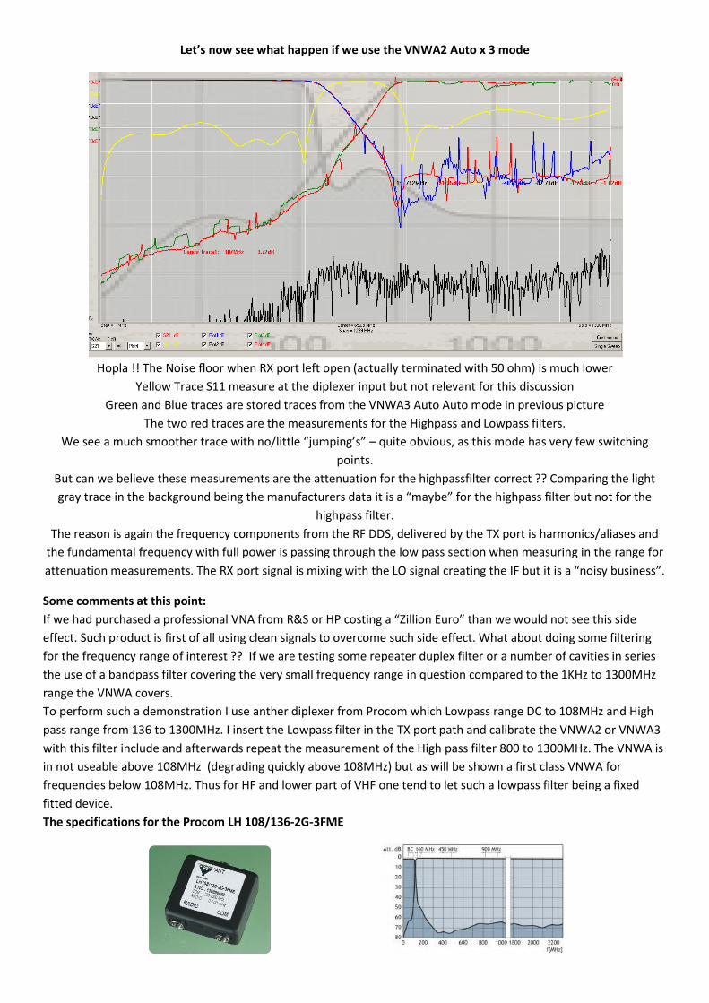
Let’s now see what happen if we use the VNWA2 Auto x 3 mode
Hopla !! The Noise floor when RX port left open (actually terminated with 50 ohm) is much lower
Yellow Trace S11 measure at the diplexer input but not relevant for this discussion
Green and Blue traces are stored traces from the VNWA3 Auto Auto mode in previous picture
The two red traces are the measurements for the Highpass and Lowpass filters.
We see a much smoother trace with no/little “jumping’s” – quite obvious, as this mode has very few switching
points.
But can we believe these measurements are the attenuation for the highpassfilter correct ?? Comparing the light
gray trace in the background being the manufacturers data it is a “maybe” for the highpass filter but not for the
highpass filter.
The reason is again the frequency components from the RF DDS, delivered by the TX port is harmonics/aliases and
the fundamental frequency with full power is passing through the low pass section when measuring in the range for
attenuation measurements. The RX port signal is mixing with the LO signal creating the IF but it is a “noisy business”.
Some comments at this point:
If we had purchased a professional VNA from R&S or HP costing a “Zillion Euro” than we would not see this side
effect. Such product is first of all using clean signals to overcome such side effect. What about doing some filtering
for the frequency range of interest ?? If we are testing some repeater duplex filter or a number of cavities in series
the use of a bandpass filter covering the very small frequency range in question compared to the 1KHz to 1300MHz
range the VNWA covers.
To perform such a demonstration I use anther diplexer from Procom which Lowpass range DC to 108MHz and High
pass range from 136 to 1300MHz. I insert the Lowpass filter in the TX port path and calibrate the VNWA2 or VNWA3
with this filter include and afterwards repeat the measurement of the High pass filter 800 to 1300MHz. The VNWA is
in not useable above 108MHz (degrading quickly above 108MHz) but as will be shown a first class VNWA for
frequencies below 108MHz. Thus for HF and lower part of VHF one tend to let such a lowpass filter being a fixed
fitted device.
The specifications for the Procom LH 108/136-2G-3FME
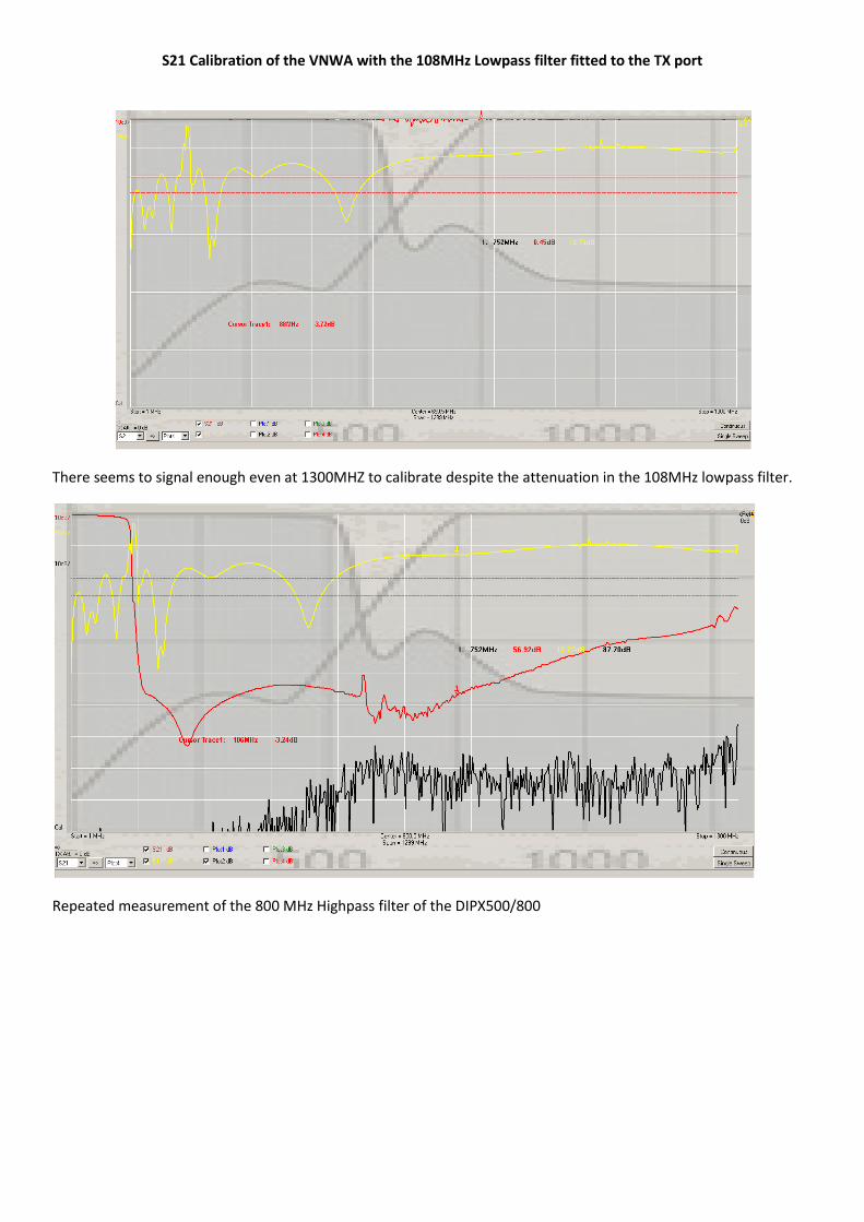
S21 Calibration of the VNWA with the 108MHz Lowpass filter fitted to the TX port
There seems to signal enough even at 1300MHZ to calibrate despite the attenuation in the 108MHz lowpass filter.
Repeated measurement of the 800 MHz Highpass filter of the DIPX500/800
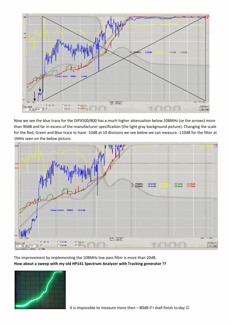
Now we see the blue trace for the DIPX500/800 has a much higher attenuation below 108MHz (se the arrows) more
than 90dB and far in excess of the manufacturer specification (the light gray background picture). Changing the scale
for the Red, Green and Blue trace to have -10dB at 10 divisions we see below we can measure -110dB for the filter at
1MHz seen on the below picture.
The improvement by implementing the 108MHz low pass filter is more than 20dB.
How about a sweep with my old HP141 Spectrum Analyzer with Tracking generator ??
It is impossible to measure more then – 80dB if I shall finish to day
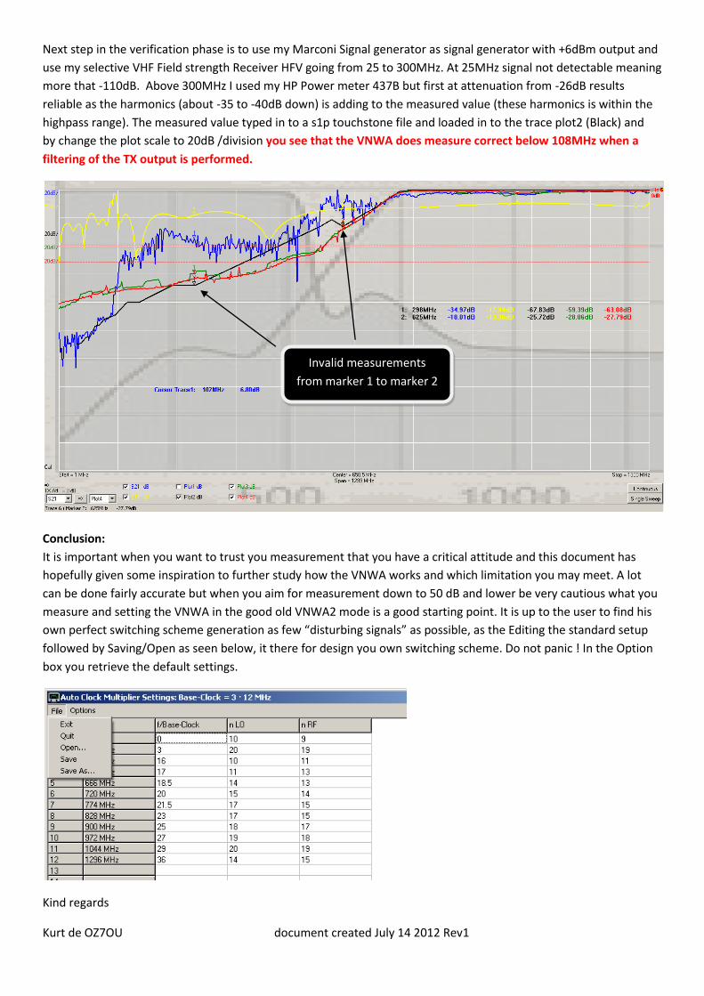
Next step in the verification phase is to use my Marconi Signal generator as signal generator with +6dBm output and
use my selective VHF Field strength Receiver HFV going from 25 to 300MHz. At 25MHz signal not detectable meaning
more that -110dB. Above 300MHz I used my HP Power meter 437B but first at attenuation from -26dB results
reliable as the harmonics (about -35 to -40dB down) is adding to the measured value (these harmonics is within the
highpass range). The measured value typed in to a s1p touchstone file and loaded in to the trace plot2 (Black) and
by change the plot scale to 20dB /division you see that the VNWA does measure correct below 108MHz when a
filtering of the TX output is performed.
Conclusion:
It is important when you want to trust you measurement that you have a critical attitude and this document has
hopefully given some inspiration to further study how the VNWA works and which limitation you may meet. A lot
can be done fairly accurate but when you aim for measurement down to 50 dB and lower be very cautious what you
measure and setting the VNWA in the good old VNWA2 mode is a good starting point. It is up to the user to find his
own perfect switching scheme generation as few “disturbing signals” as possible, as the Editing the standard setup
followed by Saving/Open as seen below, it there for design you own switching scheme. Do not panic ! In the Option
box you retrieve the default settings.
Kind regards
Kurt de OZ7OU document created July 14 2012 Rev1
Invalid measurements
from marker 1 to marker 2