Embed Size (px)
Citation preview

Machine Vision and Applications (2010) 21:713–725DOI 10.1007/s00138-009-0188-9
ORIGINAL PAPER
Wide-baseline stereo vision for terrain mapping
Clark F. Olson · Habib Abi-Rached
Received: 11 January 2008 / Revised: 30 July 2008 / Accepted: 7 January 2009 / Published online: 6 February 2009© Springer-Verlag 2009
Abstract Terrain mapping is important for mobile robots toperform localization and navigation. Stereo vision has beenused extensively for this purpose in outdoor mapping tasks.However, conventional stereo does not scale well to distantterrain. This paper examines the use of wide-baseline ste-reo vision in the context of a mobile robot for terrain map-ping, and we are particularly interested in the application ofthis technique to terrain mapping for Mars exploration. Inwide-baseline stereo, the images are not captured simulta-neously by two cameras, but by a single camera at differentpositions. The larger baseline allows more accurate depthestimation of distant terrain, but the robot motion betweencamera positions introduces two new problems. One issue isthat the robot estimates the relative positions of the camera atthe two locations imprecisely, unlike the precise calibrationthat is performed in conventional stereo. Furthermore, thewide-baseline results in a larger change in viewpoint than inconventional stereo. Thus, the images are less similar and thismakes the stereo matching process more difficult. Our meth-odology addresses these issues using robust motion estima-tion and feature matching. We give results using real images
Portions of this work have previously appeared in the Proceedings ofthe IEEE/RSJ International Conference on Intelligent Robots andSystems [34] and in the Proceedings of the 12th InternationalConference on Advanced Robotics [33]. A summary of an earlyversion of this work appears in [36].
C. F. Olson (B)Computing and Software Systems, University of Washington,Box 358534, 18115 Campus Way NE, Bothell, WA 98011, USAe-mail: [email protected]
H. Abi-RachedDepartment of Electrical Engineering, University of Washington,Box 352500, 253 EE/CSE Building, Seattle, WA 98195, USA
of terrain on Earth and Mars and discuss the successes andfailures of the technique.
Keywords Stereo vision · Wide-baseline matching ·Terrain mapping · Motion estimation
1 Introduction
Terrain mapping is critical to mobile robot navigation in out-door environments. If a robot cannot sense the pathways andobstacles to the goal location, then considerable trial-and-error may be performed before finding a navigable route.Maps are also useful for performing localization of the robotand finding the goal, particularly when Global PositioningSystem (GPS) data is not available.
We are interested in performing terrain mapping for therobotic exploration of Mars. An important goal for Marsexploration is to maximize the amount of scientific datareturned during a mission. The amount of such data isincreased if a rover is able to traverse to distant science tar-gets in a single command cycle. However, this requires therover to be able to navigate to science targets seen in orbi-tal images, but not previously seen by the rover. Inaccuratenavigation to these goals leads to a reduction in the time forgathering scientific data, since communications from Earthare usually received only once per day. When the rover failsto correctly reach the target, it must again be commanded totraverse to the correct location.
Previous work [16,31,35,49] has addressed several issuesin mapping and localization for rovers. However, this workhas not solved the problem of on-board mapping of distantterrain by a rover, which would allow a rover to improveits long-range planning and localization capabilities. Cur-rent rovers use stereo vision for mapping nearby terrain, but
123

714 C. F. Olson, H. Abi-Rached
Fig. 1 As the baseline distanceincreases, the stereo range erroris decreased, assuming that theerror in estimating the disparitydoes not increase linearly withthe baseline distance
the accuracy of such techniques degrades with the square ofthe distance to the terrain. This can be improved through theuse of a larger baseline distance (the distance between thestereo cameras). On the other hand, a rover cannot have twocameras with a large, fixed baseline distance because of thelimited size of the rover.
Rather than using two images taken by different camerasat the same time, wide-baseline stereo vision uses two imagestaken by the same camera at different times. The wide base-line can improve the quality of the stereo range data for dis-tant terrain. This can be observed by noting that the stereodisparity d is inversely proportional to the depth of the pointz and directly proportional to the baseline distance b. So,z = cb/d, where c is constant. In practice, the disparity mustbe estimated with some error and this yields error in the esti-mate of the distance to the point. However, as the baselineis increased, the disparity increases proportionally and thiscauses a reduction in the effect of the error in the disparityestimate. This effect is illustrated in Fig. 1.
However, two new problems are introduced. First, we canno longer carefully calibrate the difference in location andorientation between the camera positions, since they are notfixed as in conventional stereo vision. These positions areonly known up to the accuracy of the rover localization asit moves in the terrain. In addition, finding the stereo corre-spondences between the images is more difficult, since theterrain is seen with a larger difference in perspective than inconventional stereo.
Our methodology addresses these problems. We performthe following steps:
1. Motion refinement: We refine an estimate of the cameraposition using matches between image features detectedin the images (an initial estimate is not crucial, but itis typically available from rover odometry). We do notassume that the initial estimate is precise. A refinementstep is performed in order to improve the relative cameraposition estimate, consisting of the following substeps:
(a) Feature selection: We detect features in the firstimage that can be precisely localized using a methodbased on the approaches of Förstner and Gülch [3]and Shi and Tomasi [41].
(b) Feature matching: For each feature, we look for acorresponding feature in the second image using ahierarchical search over the entire image with mul-tiple candidates at each level. A high-pass filter isapplied to both images prior to matching to removemost illumination effects.
(c) Outlier rejection: We reject correspondences wherethe estimated precision is low, multiple candidatesare similar, or the disparity is not in agreement withother matches.
(d) Motion estimation: The Levenberg-Marquardt algo-rithm [38] is used to optimize the motion param-eters with respect to the epipolar constraints forthe detected correspondences. A robust objectivefunction is used to minimize the distances betweenthe matched feature locations in the second imageand the locations reprojected from the first imageinto the second image using the estimated motionparameters.
2. Image rectification: We rectify the images using the algo-rithm of Fusiello et al. [5] so that the correspondencesbetween the images lie along the same image row. Thisallows the disparity for each pixel to be computed effi-ciently.
3. Stereo matching: We use our maximum-likelihood imagematching measure [32] to compute disparity estimatesfor each pixel in the first image. The search efficiency isimproved by eliminating redundant computationsbetween neighboring pixels. We estimate the subpixeldisparity value and the precision of the disparity by fit-ting a parameterized surface the estimated likelihoods.Outliers are rejected using the precision estimates andby eliminating small regions of the disparity image thatare inconsistent with surrounding estimates.
123

Wide-baseline stereo vision for terrain mapping 715
4. Triangulation: The image disparities are used to trian-gulate the three-dimensional position of each location inthe terrain.
While we discuss novel techniques as a part of the com-ponents of our system, the primary purpose of this work is todescribe a complete system for wide-baseline stereo vision.Given maps created at several overlapping locations, severalmethods can be used to merge them into a larger encompass-ing map [9,36,37,44]. The following sections describe theabove steps in further detail and present experiments testingthe efficacy of the methodology.
2 Previous work
Indoor mapping has received considerable attention in therobotics community. Thrun [44] gives a good review of suchwork. Outdoor mapping has received much less attention.Most work on outdoor mapping has concentrated on stereovision or laser rangefinders, owing to the complex terrain,but other sensors have been used.
Early work at Carnegie Mellon University used scanninglaser rangefinders to perform outdoor mapping [7,12–14].Gennery [6] and Matthies [23,24] used stereo vision data forsimilar purposes at the Jet Propulsion Laboratory (JPL).
More recent techniques deal with highly complex data.Maimone et al. [19] used trinocular stereo vision to map dif-ficult terrain for use in the Chornobyl nuclear facility. Huberand Hebert [9] built maps for large data sets of unstructuredterrain with widely varying resolution. Mandelbaum et al.[21] constructed maps with single or stereo cameras over longdistances using structure and motion estimation. Li et al. [17]generated maps of Mars using data acquired by the Spirit andOpportunity rovers.
Terrain mapping has also been performed using aerialimages. Hung et al. [10] generated terrain models from over-lapping aerial images. At the National Center for ScientificResearch in France (CNRS), an autonomous blimp was usedto acquire stereo imagery for mapping [11,15]. Xiong et al.[49] developed methods to generate maps from the imagescaptured as a spacecraft descends to a planetary body. Mont-gomery et al. [27] generated maps using an autonomous heli-copter for safe landing. Williams et al. [47] used sonar formapping and navigation in underwater robotics.
Wide-baseline stereo (also called motion stereo [8,29])can map terrain that is more distant than conventional stereo,because the larger baseline allows improved triangulation.Much recent work in this area has considered the problem offinding correspondences between the wide-baseline images[1,18,22,25,39,40,46]. In contrast, our work uses a rela-tively simple method for finding correspondences and con-centrates on building a system capable of generating dense
and accurate depth maps from wide-baseline images. The useof an alternative method for detecting correspondences hasthe potential for improving our system.
Other interesting work includes the method of Strechaet al. [42] for dense mapping of wide-baseline images. Thistechnique generates excellent results, but is not suitable for amobile robot because of the required processing time. Finally,Okutomi and Kanade [30] describe a system for generatingstereo data using a set of images with different baselines.However, the baselines in this work are not wide.
3 Feature selection and matching
The first step in accurately recovering the terrain map is torefine the estimated motion between the camera positions.An initial estimate is typically given by rover odometry orother localization methods. This estimate can be refined usingmotion estimation, if we know correspondences between theimages. This section is concerned with locating such corre-spondences. Since the images are not captured at the sametime, the illumination of the terrain may be different in thetwo images. In order to remove most of the effects of suchchanges, we convolve both images with a high-pass filter,replacing each pixel with the deviation from the average localbrightness.
It is impractical to determine correspondences for everylocation in the observed terrain for several reasons. Somelocations that can be seen in one image will not be observedin the other. Correspondences for other locations cannot befound precisely, since the terrain has a uniform appearance.Furthermore, the processing time needed to detect correspon-dences for each location would be prohibitive. We select 256locations with distinctive appearance from the first image tomatch with the second image. The distinctiveness of the fea-ture is determined using a method based on the similar inter-est operators developed by Förstner [3] and Shi and Tomasi[41]. The operator scores each pixel based on the strengthof the gradients in a neighborhood around the pixel. For apixel to score highly, the neighborhood must have stronggradients with multiple orientations. Requiring the gradientsto have multiple orientations allows linear edges to be dis-carded, which is desirable, since it is hard to localize featuresalong the edge. This operator examines the covariance matrixof the local gradients. The larger eigenvalue of the covariancematrix is an estimate of the strength of the gradients in theneighborhood and the ratio of the eigenvalues measures thedegree to which they are in multiple orientations. FollowingShi and Tomasi [41], we score each pixel according to valueof the smaller eigenvalue.
Once the image locations have been scored, we divide theimage into an even grid of 16 sub-images and select localmaxima within each sub-image. This ensures that we select
123

716 C. F. Olson, H. Abi-Rached
0 0.02 0.04 0.06 0.08 0.1 0.12 0.14 0.160
0.05
0.1
0.15
0.2
0.25
Threshold on estimated st. dev. of match position
Med
ian
repr
ojec
tion
erro
r
0 200 400 600 800 1000 1200 1400 1600 1800 20000
0.05
0.1
0.15
0.2
0.25
Threshold on difference between top two SAD scores
Med
ian
repr
ojec
tion
erro
r
0 2000 4000 6000 8000 10000 12000 14000 16000 180000
0.05
0.1
0.15
0.2
0.25
Threshold on SAD distance
Med
ian
repr
ojec
tion
erro
r
(c)(b)(a)
Fig. 2 Experiments indicate that the methodology is insensitive to thethresholds chosen for accepting candidate feature matches. a Plot of themedian reprojection error versus the threshold on the estimated stan-dard deviation of match position. b Plot of the median reprojection error
versus the threshold on the SAD distance between top two matches.c Plot of the median reprojection error versus the threshold on the SADscore of top match
features from all parts of the image. However, the maximain each sub-image are subject to a threshold, since we donot want featureless sub-images to contribute to the set ofselected features.
For each selected feature, a match is sought in the secondimage using a coarse-to-fine strategy. The method first detectscandidate matches in an image that has been downsampledby four in both rows and columns (the Mars rover images thatwe test on are 1,024×1,024 pixels, but other image sizes arealso used). We perform matching using the sum-of-absolute-differences (SAD) distance over a large window (21×21)so that considerable image context is incorporated. However,the large context can lead to a large SAD distance betweenimage patches, even for correct matches, if there is a changein appearance between images. For this reason, multiple can-didate matches are selected at the low resolution if the SADdistance is not more than 50% larger than the distance for thebest candidate (up to a maximum of ten candidates).
Each candidate match is refined at the highest resolutionusing a small (9×9) search space and candidates are removedif they do not remain within 50% of the best SAD distance.Finally, candidates undergo an (optional) affine refinementstep that uses iterative optimization to find the best fit foreach candidate match over linear transformations. We storethe best candidate if it meets four criteria (the others are dis-carded as unreliable):
1. The estimated standard deviation in the position of thelocalized match is <0.15 pixels.
2. The difference in the SAD distance between the bestmatch and the second best is ≥800.
3. The SAD distance is <12,000 (for a 21×21 window).4. The vertical disparity of the match is consistent (up to a
threshold) with the median disparity of the other candi-dates meeting the previous criteria.
Experiments varying these thresholds (see Fig. 2) indicatethat the technique is not sensitive to the precise values ofthese thresholds, owing to the consistency check and therobust objective function used in the motion estimation. Thelow tails in two of the experiments at certain thresholds isbecause many of the matches were pruned and overfitting ofthe remaining matches was possible. Note that these criteriawill often throw away correct matches in addition to incorrectmatches. It is important that most incorrect matches are dis-carded while keeping sufficient correct matches to performmotion estimation.
Figure 3 shows an example of selected and matched fea-tures using these techniques. In this case, 256 features wereselected in the first image. Of these, candidate matches werefound for 74 features in the second image. After outlier rejec-tion (which discards mostly correct matches in this case), 65correct matches remained to be used as input to the motionrefinement step.
4 Motion estimation
Given correspondences between the stereo images, we canupdate the estimated motion between the camera positionsby enforcing geometric constraints on the correspondences[43,49]. This optimization is over the rotation R and trans-lation T between the camera positions C1 and C2, whichinclude the position and orientation.
C2 = RC1 + T . (1)
In estimating the motion, only five of the six motion param-eters (three for translation and three for rotation) can be esti-mated. The distance between the camera positions (i.e., thebaseline distance) cannot be recovered, since there is a scal-ing of the entire scene that would yield the same image pairfor any such baseline distance. We use the rover onboard
123

Wide-baseline stereo vision for terrain mapping 717
Fig. 3 Feature matching example. a Features selected in the first image. b Initial features matched in first image. c Initial features matched insecond image. d Matched features in the left image after outlier rejection. e Matched features in the right image after outlier rejection
estimate for the positions where the images were capturedto compute the baseline distance. This relies on the roverlocalization capabilities [16,17,20,31] in order to estimatethe distance that the rover has traveled between capturingthe images.
In the process of optimizing the motion estimate, we use astate vector that includes the five recoverable motion param-eters and an estimate of the depth to each of the recoveredfeatures (relative to the first camera position). We initial-ize the depths to values lower than the expected distance tothe terrain. This has led to good results in our experiments.We have noticed that the optimization has converged to alocal minimum occasionally when the depths are initializedto larger values.
The objective function that we use is an M-estimator thatrobustly combines the squared error for each feature corre-spondence, where the feature error is the distance betweenthe feature position detected in the second image (ci , ri ) andthe estimated position in the second image (ci , ri ) calcu-lated by reprojecting the feature from the first image into thesecond image according to the current motion estimate andestimated feature depth.
Di =√(
ci − ci)2 + (
ri − ri)2
. (2)
We use a variation of the M-estimator discussed in [4] tocombine the distances as follows:
N∑
i=1
σ 2 D2i
σ 2 + D2i
, (3)
where σ = median(D1, . . . , DN ) and N is the number ofcorrespondences. The objective function is optimized usingthe Levenberg-Marquardt method [38].
When we applied this technique to the images in Fig. 3,the average reprojection error per feature was 0.096 pixels. Ina series of more difficult tests, the median reprojection errorwas 0.15 pixels. The techniques were also tested on a dataset with a known homography between image pairs [26]. Inthis experiment, we compared the locations that the pointswere predicted to be projected according to the motion esti-mate with the location specified by the homography. Figure 4shows the results. The histograms indicate that the errors areusually small.
5 Rectification
The location of any position in the terrain that is seen inthe first image is constrained to lie along a line in the sec-ond image. This is called the epipolar constraint and theline is called the epipolar line. If the camera parametersand the motion between the images are known, then wecan make use of this constraint. The location of the posi-tion in the second image along this line depends on the
123

718 C. F. Olson, H. Abi-Rached
−4 −3 −2 −1 0 1 2 3 40
0.02
0.04
0.06
0.08
0.1
0.12
0.14
0.16
Distance (pixels)
Fra
ctio
nErrors in x−direction
−4 −3 −2 −1 0 1 2 3 40
0.05
0.1
0.15
0.2
0.25
Distance (pixels)
Fra
ctio
n
Errors in y−direction
0 0.5 1 1.5 2 2.5 30
0.01
0.02
0.03
0.04
0.05
0.06
0.07
0.08
0.09
0.1
Distance (pixels)
Fra
ctio
n
Total error
(c)(b)(a)
Fig. 4 Motion errors computed by comparing the projected feature locations according to the estimated motion to the location predicted by theknown homography. a Histogram of errors in the x-direction. b Histogram of errors in the y-direction. c Histogram of overall error distances
distance of the terrain from the camera. A common and use-ful trick in stereo vision is to rectify the images to appear asif they were captured by cameras with horizontal axes thatare parallel to the baseline and vertical axes that are per-pendicular to both the baseline and the optical axes. Thiscorresponds to a virtual rotation of each camera about itscenter of projection and can be achieved by a linear transfor-mation of the image (this assumes a pinhole camera model.In practice, most lens distortion can be removed prior to thisstep, if a model of the distortion is computed in advance).When this rectification has been performed, all of the epi-polar lines become horizontal and they lie along the sameimage row as the corresponding image feature. This allowsefficient algorithms to be used to find the stereo correspon-dences.
We use the method of Fusiello et al. [5] to perform rec-tification. If R1 and C1 are the camera rotation matrix andcenter of projection for the first image in the world coordi-nate frame, then a point at [x y z]T is transformed accordingto the perspective projection into an image point [u1 v1]T
by taking the intersection of the image plane with the linebetween the point and C1.
To accomplish the rectification, we must determine therotation that brings the cameras into the correct configuration.The translation does not change. After the rectifying trans-formation, both cameras will have the same rotation matrixR, since they will have the same (virtual) orientation. Theepipolar lines will be horizontal if the baseline is parallel tothe x-axis in the camera reference frame.
We achieve the rectifying transformation by setting therotation row vectors as follows (R = [r1 r2 r3]T ):
1. r1 is a unit vector in the direction of C1 − C2.2. r2 is a unit vector orthogonal to r1 and to the z-axis in
the local frame of reference of camera 1.3. r3 is a unit vector perpendicular to both r1 and r2.
Fig. 5 Images after rectification. Lines have been added to show therelative position of features in the two images. a Left image. b Rightimage
With the new rotation matrix, the camera projection matri-ces become
Pi = A[R −RCi ] = [Q qi ], (4)
where A represents the camera intrinsic parameters, Q = ARand qi = −ARCi . The rectifying transformations are givenby
Ti = Q(ARi )−1. (5)
We apply these linear transformations to the stereo images.This sometimes transforms the image pixels such that theyare moved outside of the image (for example, if the originalforward axes converged). We recenter the images in order toretain as much data as possible within the image boundariesby moving the center of gravity of the transformed pixel loca-tions to the center of the image. Figure 5 shows the imagesfrom Fig. 3 after rectification. The lines drawn on the imageare on corresponding rows. It can be seen that correspondingfeatures lie along the same rows in the images.
123

Wide-baseline stereo vision for terrain mapping 719
6 Stereo matching
In wide-baseline stereo matching, there is often a large (pos-itive or negative) disparity between corresponding points inthe two images. This necessitates a large search space in thehorizontal dimension for the correct match. However, afterthe image rectification we do not need to search in the verticaldirection. This allows us to combine efficient stereo matchingtechniques with a robust image matching measure.
To find the correspondences, we use an area-based strat-egy, where a small neighborhood around each pixel in thefirst image is used to compare against small neighborhoodsin the second image. In our experiments, the use of a simplemeasure such as sum-of-squared-differences (SSD), SAD, ornormalized correlation produced poor results. We use a max-imum-likelihood image matching strategy that produces bet-ter results [32]. Typical measures compare only the pixels thatare aligned between the neighborhoods in the two images. Forexample, the SSD squares the differences between these pix-els and sums the results. The maximum-likelihood matchingstrategy allows matches between pixels that are not directlyoverlapping, if the intensities are sufficiently similar, usinga pixel similarity measure that combines the difference inintensity with distance between them. To compute the mea-sure, pixels in the images are considered to be vectors in thethree-dimensional space spanning the pixel row, column, andintensity. However, a difference of one unit in intensity is notas important as a difference of one unit in the row or columnof the pixel, so a weighting factor K is used to discount thedistance in intensity. Let
vi =
⎡⎢⎢⎣
p(row)i
p(column)i
K p(intensity)i
⎤⎥⎥⎦ . (6)
For simplicity, the distance between pi and p j is computedwith the L1 norm:
d(pi , p j ) = ∣∣∣∣vi − v j∣∣∣∣
1 . (7)
We have found empirically that K = 1/4 works well. How-ever, the method is not sensitive to this value.
Now, let dδr,c be the distance (computed with respect to the
above definition) from the pixel at (r, c) in the first image tothe closest pixel in the second image when it is displaced bydisparity δ. This can be computed efficiently using a three-dimensional distance transform [31]. The likelihood functionover the neighborhood of a pixel at (r, c), given the disparityis
Lδ(r, c) =w∏
i=−w
w∏
j=−w
f (dδr+i,c+ j ), (8)
where f (·) is the probability density function (PDF) of thedistances and w determines the size of the neighborhood
(this assumes independence between the distances, whichworks well in practice). We use a PDF that is a weightedmixture of a Gaussian for inliers and a constant for outliers[32].
In order to perform dense matching between the recti-fied images using the measure described above, we use anefficient search strategy common in stereo vision [2,28].This strategy makes use of the observation that a brute-forceimplementation performs many redundant computations foradjacent positions of the template at the same disparity. Weeliminate the redundant computation by storing the informa-tion for reuse as necessary for fast matching.
Given previously computed values Lδ(r −1, c), Lδ(r, c−1), and Lδ(r −1, c −1), we can compute Lδ(r, c) efficientlywith the following formulas:
r+ = r + w (9)
r− = r − w − 1 (10)
c+ = c + w (11)
c− = c − w − 1 (12)
Lδ(r, c) = Lδ(r−1, c)Lδ(r, c−1) f (dδr−,c−) f (dδ
r+,c+)
Lδ(r−1, c−1) f (dδr−,c+) f (dδ
r+,c−)(13)
In practice, it is faster to compute log Lδ(r, c), since log f (·)can be precomputed for the necessary values and this resultsin only the use of addition and subtraction (rather than mul-tiplication and division).
We select the disparity that maximizes the likelihood func-tion as the candidate disparity for each pixel. A subpixel dis-parity estimate and an estimate of the standard deviation ofthe error for each pixel are computed by fitting a curve to thelikelihood scores near the maxima [31]. The disparity is dis-carded if the standard deviation is too large or if the overalllikelihood of the location is not large enough. A final outlierrejection step is used that discards any disparities that do notform a large enough coherent block in the output.
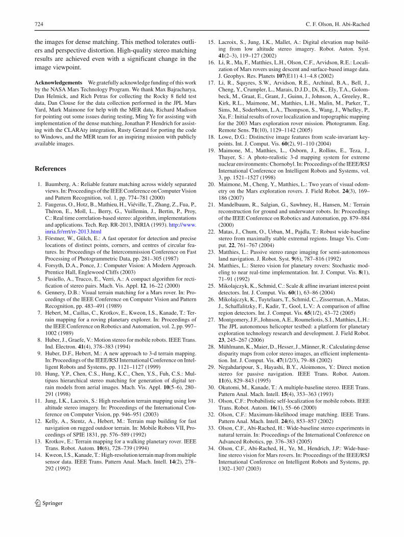
Figure 6 shows the disparity map that was computed forthe example in the previous figures, which show the Endur-ance crater on Mars imaged by the Opportunity rover. Denseresults are achieved for the far side of the crater where itappears in both of wide-baseline images. Results on the leftside are correctly pruned, since this part of the crater is notvisible in both images. Data at the bottom is pruned eitherfor this reason or because the change in appearance is large.Figure 7 shows a second example, which is a conventionalstereo pair of Mars. Dense results are obtained over most ofthe image in this case, since the cameras were pointing innearly the same direction and the baseline was small. Datais correctly pruned from the left side of the image, since thisregion is not visible in both images. The results are very closeto those obtained by conventional stereo. This is an encour-aging result, since conventional stereo benefited from the
123

720 C. F. Olson, H. Abi-Rached
Fig. 6 Computed disparity map for Endurance crater wide-baselinestereo pair. a Left image. b Disparity image. Dark values representlarger disparities
Fig. 7 Computed disparity map for Mars Pathfinder narrow-baselinestereo pair. a Left image. b Disparity image. Dark values representlarger disparities
carefully calibrated external parameters, whereas our meth-odology did not.
7 Triangulation
The triangulated position p1 of a point with respect to the(rectified) first camera frame can be computed using the coor-dinates of the feature in the first image (r, c1), the coordi-nates of the corresponding feature in the second image (r, c2)
and the camera parameters. Let A1 and A2 be the cameraprojection matrices (which will differ only in the projectedlocation of the center of projection), R be the camera rotationin the global reference frame (it is the same for both camerasafter rectification), and C1 and C2 be the camera centers ofprojection.
Define:
S1 = (A1 R)−1 (14)
S2 = (A2 R)−1 (15)
a = S(0,0)1 c1 + S(0,1)
1 r + S(0,2)1 (16)
b = S(2,0)1 c1 + S(2,1)
1 r + S(2,2)1 (17)
c = S(0,0)2 c2 + S(0,1)
r r + S(0,2)2 (18)
d = S(2,0)2 c2 + S(2,1)
r r + S(2,2)2 (19)
l1 = (dC (0)1 − C (0)
2 − cC (2)1 + C (2)
2 )/(bc − ad) (20)
The triangulated position is given by
p1 = C1 + l1S1 [c1 r 1]T , (21)
8 Experiments
We have performed experiments with these techniques onimages of natural terrain of sandy and rocky terrain (similarto Mars). Some tests used actual images of Mars from theSpirit and Opportunity rovers or from the Mars Pathfindermission. The first experiment tested a variety of baselinesusing data collected at JPL using the Rocky 8 rover proto-type. A sequence of 11 images was captured with roughly20 centimeter intervals between the camera locations in theJPL Mars Yard using the navigation cameras on the rovermast. This allows us to consider stereo pairs with baselinedistances ranging from 20 centimeters to 2 meters. All of theimages in the sequence were captured with a camera orienta-tion that is largely perpendicular to the direction of travel, seeFig. 8.
Figure 9 shows the disparity maps that were generatedfrom this sequence. The first image in the sequence was usedin each wide-baseline pair, with every other image servingas the second image in one pair. The disparities are renderedrelative to the position of the pixel in the first image. It can beseen in this data that the coverage of the stereo data is largerfor image pairs with a smaller baseline. One reason for thisis that there is a smaller overlap in the terrain visible in theimage pair when the baseline is increased. This causes the tri-angular region on the lower-left that contains no disparities.A second reason for the lower coverage is that, as the camerapositions become farther apart, the change in the appearanceof the terrain becomes larger (the terrain is viewed from adifferent perspective). This makes the correspondence prob-lem more difficult and the verification techniques eliminatemore of the disparity data. It is worth noting that the goal ofwide-baseline stereo vision is to map the more distant ter-rain, so that failure on nearby terrain (which can be mappedwith a smaller baseline) is not a large drawback. The verifica-tion techniques are largely successful in eliminating outliers.However, they are not perfect. An outlier region that was notsuccessfully pruned can be seen in the lower-left of the sec-ond image. In addition, correct data is sometimes pruned bythe techniques.
We can evaluate the quality of the more distant range datain this experiment by examining the shape and accuracy ofthe range data to the vertical wall present at the top of eachimage. Conventional stereo techniques with a 20 cm baseline
123

Wide-baseline stereo vision for terrain mapping 721
Fig. 8 Image sequence from the JPL Mars Yard. The images were taken at intervals of approximately 20 cm
did not achieve high accuracy in the shape of the wall, sinceit was roughly 20 m from the rover. Our techniques also didnot achieve high accuracy with a 20 cm baseline, see Fig. 10.The estimated shape of the wall (which should be planar)was improved as the baseline was increased. Quantitativeerror was present in some cases because of a small numberof feature matching errors that caused the motion estimationto converge to an incorrect local minimum. The incorrectmatches were the result of artificial objects (for example, thepoles rising beyond the wall). Needless to say, errors owingto the similarity of artificial objects would not occur in com-pletely natural terrain, such as on Mars.
Figure 11 shows an experiment with more distant terrain.The wide-baseline stereo pair was captured by Rocky 8 dur-ing field testing. In these images, the foreground has been
cropped, since the techniques were not successful in solv-ing the correspondence problem for this nearby terrain. Forthis experiment, the baseline distance for the stereo pair wasapproximately 5 m, but the baseline was not perpendicular tothe camera axis. This resulted in a small rotation of terrain inthe rectified images. In this case, the images were capturedwith narrow field-of-view cameras, so the resolution of theimages is high. The range data to the ridge seen in the imageshad high qualitative accuracy, even though the ridge was over1 km distant from the camera.
The current computation time required for the code is lessthan a minute on a 2.5 GHz personal computer. It is likelythat a careful implementation could improve upon this sig-nificantly. For a Mars rover, the wide-baseline stereo opera-tion would be performed infrequently. Since commands are
123

722 C. F. Olson, H. Abi-Rached
Fig. 9 Disparity maps generated from Mars Yard sequence. Each dis-parity map was created using the wide-baseline stereo algorithm withimage 1 as the first image and image n + 1 as the second image. The
baseline distance ranges from 20 for the first disparity map to 2 m for thelast disparity map. Black pixels indicate that the disparity was prunedat that location
Fig. 10 Overhead view of thepoint cloud generated usingwide-baseline stereo for the wallseen at the top of the images inFig. 8. a 20 cm baseline. b 40 cmbaseline. c 100 cm baseline.d 200 cm baseline
123

Wide-baseline stereo vision for terrain mapping 723
Fig. 11 Wide-baseline stereopair of the California desertcaptured by Rocky 8 prototype.a Left image. b Right image.c Feature matches in left image.d Feature matches in rightimage. e Rectified left image.f Disparity map for left image
received infrequently from Earth, a short wait for results islikely to be acceptable.
9 Failure modes
It is important to consider the conditions under which thewide-baseline stereo techniques fail. One failure mode forthese techniques is the inability to establish correspondencesbetween the wide-baseline images. This can occur for mul-tiple reasons. For example, the images may not capture thesame terrain or the terrain may be uniform, such that nodistinctive features exist. Nothing can be done about thesesituations, except to modify the rover operation in order tocapture a better pair of images.
Problems can also occur in feature matching when theappearance between the images changes drastically. We cansee this in the nearby terrain in several of the examples givenhere. Large baselines are better for mapping distant terrainthan nearby terrain. Often conventional stereo can be usedfor mapping the nearby terrain. We have found that this canbe improved upon by capturing images of the terrain at morethan two rover positions, with baselines ranging from smallto large. This sequence of baselines allows mapping of bothnear and far terrain. It can also improve the depth estimateon terrain captured in more than two images.
We have seen that incorrect feature matching sometimesadversely affects the motion estimate and this can causepoor results. In our experiments, such incorrect tracking has
occurred primarily for artificial objects, rather than naturalterrain, owing to objects with a very similar appearance. It islikely that the presence of incorrect matches in these casescan be addressed through the use of a random sampling tech-nique, such as RANSAC, to eliminate the incorrect matchesprior to the iterative estimation step [45].
In order for the rectification to be accurate over the entireimage, it is important that the sparse correspondences used inthe motion estimate cover the image well. Areas that are notwell covered by such correspondences tend to be fit poorlyand, thus, the rectification performs less well in these areas.We have concentrated less on this problem than others, sincethis problem occurs primarily for closer terrain. However,this could be improved through the use of feature matchingstrategies that are robust to affine transformations [1,46,48].
10 Summary
We have developed an algorithm to perform wide-baselinestereo on a mobile robot. Unlike conventional stereo vision,these techniques allow the robot to map terrain that is manymeters (up to a few kilometers) distant. This has requiredthe solution to two problems. We have addressed inexactknowledge of the relative positions between the camerasusing nonlinear motion estimation. This step automaticallyselects features and determines correspondences between theimages in order to refine the motion estimate to satisfy epipo-lar constraints. We use robust template matching techniquesto deal with the increased change in appearance between
123
724 C. F. Olson, H. Abi-Rached
the images for dense matching. This method tolerates outli-ers and perspective distortion. High-quality stereo matchingresults are achieved even with a significant change in theimage viewpoint.
Acknowledgements We gratefully acknowledge funding of this workby the NASA Mars Technology Program. We thank Max Bajracharya,Dan Helmick, and Rich Petras for collecting the Rocky 8 field testdata, Dan Clouse for the data collection performed in the JPL MarsYard, Mark Maimone for help with the MER data, Richard Madisonfor pointing out some issues during testing, Ming Ye for assisting withimplementation of the dense matching, Jonathan P. Hendrich for assist-ing with the CLARAty integration, Rusty Gerard for porting the codeto Windows, and the MER team for an inspiring mission with publiclyavailable images.
References
1. Baumberg, A.: Reliable feature matching across widely separatedviews. In: Proceedings of the IEEE Conference on Computer Visionand Pattern Recognition, vol. 1, pp. 774–781 (2000)
2. Faugeras, O., Hotz, B., Mathieu, H., Viéville, T., Zhang, Z., Fua, P.,Théron, E., Moll, L., Berry, G., Vuillemin, J., Bertin, P., Proy,C.: Real time correlation-based stereo: algorithm, implementationsand applications. Tech. Rep. RR-2013, INRIA (1993). http://www.inria.fr/rrrt/rr-2013.html
3. Förstner, W., Gülch, E.: A fast operator for detection and preciselocations of distinct points, corners, and centres of circular fea-tures. In: Proceedings of the Intercommission Conference on FastProcessing of Photogrammetric Data, pp. 281–305 (1987)
4. Forsyth, D.A., Ponce, J.: Computer Vision: A Modern Approach.Prentice Hall, Englewood Cliffs (2003)
5. Fusiello, A., Trucco, E., Verri, A.: A compact algorithm for recti-fication of stereo pairs. Mach. Vis. Appl. 12, 16–22 (2000)
6. Gennery, D.B.: Visual terrain matching for a Mars rover. In: Pro-ceedings of the IEEE Conference on Computer Vision and PatternRecognition, pp. 483–491 (1989)
7. Hebert, M., Caillas, C., Krotkov, E., Kweon, I.S., Kanade, T.: Ter-rain mapping for a roving planetary explorer. In: Proceedings ofthe IEEE Conference on Robotics and Automation, vol. 2, pp. 997–1002 (1989)
8. Huber, J., Graefe, V.: Motion stereo for mobile robots. IEEE Trans.Ind. Electron. 41(4), 378–383 (1994)
9. Huber, D.F., Hebert, M.: A new approach to 3-d terrain mapping.In: Proceedings of the IEEE/RSJ International Conference on Intel-ligent Robots and Systems, pp. 1121–1127 (1999)
10. Hung, Y.P., Chen, C.S., Hung, K.C., Chen, Y.S., Fuh, C.S.: Mul-tipass hierarchical stereo matching for generation of digital ter-rain models from aerial images. Mach. Vis. Appl. 10(5–6), 280–291 (1998)
11. Jung, I.K., Lacroix, S.: High resolution terrain mapping using lowaltitude stereo imagery. In: Proceedings of the International Con-ference on Computer Vision, pp. 946–951 (2003)
12. Kelly, A., Stentz, A., Hebert, M.: Terrain map building for fastnavigation on rugged outdoor terrain. In: Mobile Robots VII, Pro-ceedings of SPIE 1831, pp. 576–589 (1992)
13. Krotkov, E.: Terrain mapping for a walking planetary rover. IEEETrans. Robot. Autom. 10(6), 728–739 (1994)
14. Kweon, I.S., Kanade, T.: High-resolution terrain map from multiplesensor data. IEEE Trans. Pattern Anal. Mach. Intell. 14(2), 278–292 (1992)
15. Lacroix, S., Jung, I.K., Mallet, A.: Digital elevation map build-ing from low altitude stereo imagery. Robot. Auton. Syst.41(2–3), 119–127 (2002)
16. Li, R., Ma, F., Matthies, L.H., Olson, C.F., Arvidson, R.E.: Locali-zation of Mars rovers using descent and surface-based image data.J. Geophys. Res. Planets 107(E11) 4.1–4.8 (2002)
17. Li, R., Squyres, S.W., Arvidson, R.E., Archinal, B.A., Bell, J.,Cheng, Y., Crumpler, L., Marais, D.J.D., Di, K., Ely, T.A., Golom-beck, M., Graat, E., Grant, J., Guinn, J., Johnson, A., Greeley, R.,Kirk, R.L., Maimone, M., Matthies, L.H., Malin, M., Parker, T.,Sims, M., Soderblom, L.A., Thompson, S., Wang, J., Whelley, P.,Xu, F.: Initial results of rover localization and topographic mappingfor the 2003 Mars exploration rover mission. Photogramm. Eng.Remote Sens. 71(10), 1129–1142 (2005)
18. Lowe, D.G.: Distinctive image features from scale-invariant key-points. Int. J. Comput. Vis. 60(2), 91–110 (2004)
19. Maimone, M., Matthies, L., Osborn, J., Rollins, E., Teza, J.,Thayer, S.: A photo-realistic 3-d mapping system for extremenuclear environments: Chornobyl. In: Proceedings of the IEEE/RSJInternational Conference on Intelligent Robots and Systems, vol.3, pp. 1521–1527 (1998)
20. Maimone, M., Cheng, Y., Matthies, L.: Two years of visual odom-etry on the Mars exploration rovers. J. Field Robot. 24(3), 169–186 (2007)
21. Mandelbaum, R., Salgian, G., Sawhney, H., Hansen, M.: Terrainreconstruction for ground and underwater robots. In: Proceedingsof the IEEE Conference on Robotics and Automation, pp. 879–884(2000)
22. Matas, J., Chum, O., Urban, M., Pajdla, T.: Robust wide-baselinestereo from maximally stable extremal regions. Image Vis. Com-put. 22, 761–767 (2004)
23. Matthies, L.: Passive stereo range imaging for semi-autonomousland navigation. J. Robot. Syst. 9(6), 787–816 (1992)
24. Matthies, L.: Stereo vision for planetary rovers: Stochastic mod-eling to near real-time implementation. Int. J. Comput. Vis. 8(1),71–91 (1992)
25. Mikolajczyk, K., Schmid, C.: Scale & affine invariant interest pointdetectors. Int. J. Comput. Vis. 60(1), 63–86 (2004)
26. Mikolajczyk, K., Tuytelaars, T., Schmid, C., Zisserman, A., Matas,J., Schaffalitzky, F., Kadir, T., Gool, L.V.: A comparison of affineregion detectors. Int. J. Comput. Vis. 65(1/2), 43–72 (2005)
27. Montgomery, J.F., Johnson, A.E., Roumeliotis, S.I., Matthies, L.H.:The JPL autonomous helicopter testbed: a platform for planetaryexploration technology research and development. J. Field Robot.23, 245–267 (2006)
28. Mühlmann, K., Maier, D., Hesser, J., Männer, R.: Calculating densedisparity maps from color stereo images, an efficient implementa-tion. Int. J. Comput. Vis. 47(1/2/3), 79–88 (2002)
29. Negahdaripour, S., Hayashi, B.Y., Aloimonos, Y.: Direct motionstereo for passive navigation. IEEE Trans. Robot. Autom.11(6), 829–843 (1995)
30. Okutomi, M., Kanade, T.: A multiple-baseline stereo. IEEE Trans.Pattern Anal. Mach. Intell. 15(4), 353–363 (1993)
31. Olson, C.F.: Probabilistic self-localization for mobile robots. IEEETrans. Robot. Autom. 16(1), 55–66 (2000)
32. Olson, C.F.: Maximum-likelihood image matching. IEEE Trans.Pattern Anal. Mach. Intell. 24(6), 853–857 (2002)
33. Olson, C.F., Abi-Rached, H.: Wide-baseline stereo experiments innatural terrain. In: Proceedings of the International Conference onAdvanced Robotics, pp. 376–383 (2005)
34. Olson, C.F., Abi-Rached, H., Ye, M., Hendrich, J.P.: Wide-base-line stereo vision for Mars rovers. In: Proceedings of the IEEE/RSJInternational Conference on Intelligent Robots and Systems, pp.1302–1307 (2003)
123

Wide-baseline stereo vision for terrain mapping 725
35. Olson, C.F., Matthies, L.H., Schoppers, M., Maimone, M.W.:Rover navigation using stereo ego-motion. Robot. Auton. Syst.43(4), 215–229 (2003)
36. Olson, C.F., Matthies, L.H., Wright, J.R., Li, R., Di, K.: Visualterrain mapping for Mars exploration. Comput. Vis. Image Und-erst. 105(1), 73–85 (2007)
37. Parker, L.E., Schneider, F.E., Schultz, A.C.: Merging partial mapswithout using odometry. In: Multi-Robot Systems. From Swarmsto Intelligent Automata, vol. III, pp. 133–144. Springer (2005)
38. Press, W.H., Teukolsky, S.A., Vetterling, W.T., Plannery, B.P.:Numerical Recipes in C. Cambridge University Press, London(1988)
39. Pritchett, P., Zisserman, A.: Wide baseline stereo matching. In:Proceedings of the International Conference on Computer Vision,pp. 765–760 (1998)
40. Schaffalitzky, F., Zisserman, A.: Viewpoint invariant texturematching and wide baseline stereo. In: Proceedings of the Interna-tional Conference on Computer Vision, vol. 2, pp. 636–643 (2001)
41. Shi, J., Tomasi, C.: Good features to track. In: Proceedings of theIEEE Conference on Computer Vision and Pattern Recognition,pp. 593–600 (1994)
42. Strecha, C., Tuytelaars, T., Van Gool, L.: Dense matching of multi-ple wide-baseline views. In: Proceedings of the International Con-ference on Computer Vision, vol. 2, pp. 1194–1201 (2003)
43. Szeliski, R., Kang, S.B.: Recovering 3d shape and motion fromimage streams using non-linear least squares. J. Vis. Commun.Image Represent. 5(1), 10–28 (1994)
44. Thrun, S.: Robotic mapping: a survey. In: Lakemeyer, G., Nebel, B.(eds.) Exploring Artificial Intelligence in the New Millennium,pp. 1–35. Morgan Kaufmann (2003)
45. Torr, P.H.S., Murray, D.W.: The development and comparison ofrobust methods for estimating the fundamental matrix. Int. J. Com-put. Vis. 24(3), 271–300 (1997)
46. Tuytelaars, T., Gool, L.V.: Matching widely separated views basedon affine invariant regions. Int. J. Comput. Vis. 59(1), 61–85 (2004)
47. Williams, S., Dissanayake, G., Durrant-White, H.: Towards ter-rain-aided navigation for underwater robotics. Adv. Robot. 15,533–549 (2001)
48. Xiao, J., Shah, M.: Two-frame wide baseline matching. In: Pro-ceedings of the International Conference on Computer Vision, pp.603–609 (2003)
49. Xiong, Y., Olson, C.F., Matthies, L.H.: Computing depth mapsfrom descent images. Mach. Vis. Appl. 16(3), 139–147 (2005)
Author biographies
Clark F. Olson received the B.S. degree in Computer Engineering in1989 and the M.S. degree in Electrical Engineering in 1990, both fromthe University of Washington, Seattle. He received the Ph.D. degree inComputer Science in 1994 from the University of California, Berkeley.After spending 2 years doing research at Cornell University, he movedto the Jet Propulsion Laboratory (JPL), where he spent 5 years workingon computer vision techniques for Mars rovers and other applications.Dr. Olson joined the Faculty at the University of Washington, Bothell in2001. His research interests include computer vision and mobile robot-ics. He teaches classes on the mathematical principles of computingand database systems, and he continues to work with NASA/JPL.
Habib Abi-Rached was born in Zahle, Lebanon. The son of a lawyerand a French literature teacher, he traveled throughout the world. Heearned a degree in Electrical Engineering from the University ofLebanon, followed by a Diplome d’Ingenieur, a Mastere Specialiseand a Diplome D’Etudes Approfondies in Computer Science fromENSEEIHT in Toulouse. In 2006, he earned a Doctor of Philosophyat the University of Washington in Computer Science. Currently heworks for SPC, a bio-informatics company in Seattle.
123