Embed Size (px)
Citation preview
OM-914273-0715-C
WILDCAT 65K MODEL WC 65R 65,000 LB INDUSTRIAL WINCH
CAUTION: READ AND UNDERSTAND THIS MANUAL BEFORE INSTALLATION AND OPERATION OF WINCH. SEE WARNINGS!
OPERATING, SERVICE AND MAINTENANCE MANUAL
3
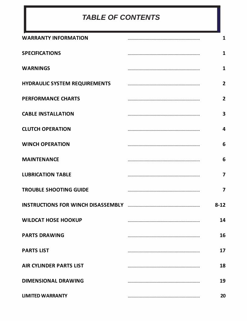
TABLE OF CONTENTS
WARRANTY INFORMATION …………………………………………………… 1
SPECIFICATIONS …………………………………………………… 1
WARNINGS …………………………………………………… 1
HYDRAULIC SYSTEM REQUIREMENTS …………………………………………………… 2
PERFORMANCE CHARTS …………………………………………………… 2
CABLE INSTALLATION …………………………………………………… 3
CLUTCH OPERATION …………………………………………………… 4
WINCH OPERATION …………………………………………………… 6
MAINTENANCE …………………………………………………… 6
LUBRICATION TABLE …………………………………………………… 7
TROUBLE SHOOTING GUIDE …………………………………………………… 7
INSTRUCTIONS FOR WINCH DISASSEMBLY …………………………………………………… 8-12
WILDCAT HOSE HOOKUP …………………………………………………… 14
PARTS DRAWING …………………………………………………… 16
PARTS LIST …………………………………………………… 17
AIR CYLINDER PARTS LIST …………………………………………………… 18
DIMENSIONAL DRAWING …………………………………………………… 19
LIMITED WARRANTY …………………………………………………… 20
1
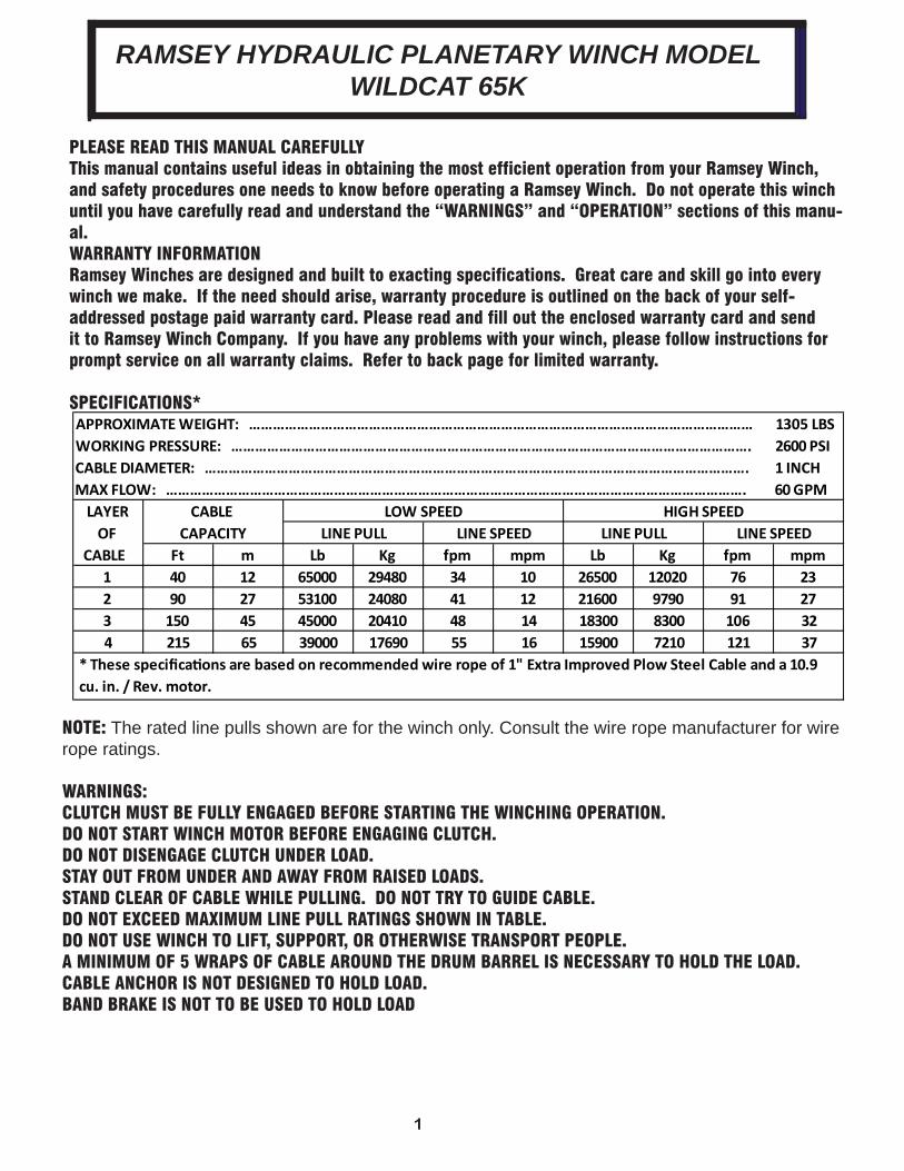
PLEASE READ THIS MANUAL CAREFULLYThis manual contains useful ideas in obtaining the most efficient operation from your Ramsey Winch, and safety procedures one needs to know before operating a Ramsey Winch. Do not operate this winch until you have carefully read and understand the “WARNINGS” and “OPERATION” sections of this manu-al.WARRANTY INFORMATIONRamsey Winches are designed and built to exacting specifications. Great care and skill go into every winch we make. If the need should arise, warranty procedure is outlined on the back of your self-addressed postage paid warranty card. Please read and fill out the enclosed warranty card and send it to Ramsey Winch Company. If you have any problems with your winch, please follow instructions for prompt service on all warranty claims. Refer to back page for limited warranty.
SPECIFICATIONS*
NOTE: The rated line pulls shown are for the winch only. Consult the wire rope manufacturer for wire rope ratings.
WARNINGS:CLUTCH MUST BE FULLY ENGAGED BEFORE STARTING THE WINCHING OPERATION.DO NOT START WINCH MOTOR BEFORE ENGAGING CLUTCH.DO NOT DISENGAGE CLUTCH UNDER LOAD.STAY OUT FROM UNDER AND AWAY FROM RAISED LOADS.STAND CLEAR OF CABLE WHILE PULLING. DO NOT TRY TO GUIDE CABLE.DO NOT EXCEED MAXIMUM LINE PULL RATINGS SHOWN IN TABLE.DO NOT USE WINCH TO LIFT, SUPPORT, OR OTHERWISE TRANSPORT PEOPLE.A MINIMUM OF 5 WRAPS OF CABLE AROUND THE DRUM BARREL IS NECESSARY TO HOLD THE LOAD.CABLE ANCHOR IS NOT DESIGNED TO HOLD LOAD. BAND BRAKE IS NOT TO BE USED TO HOLD LOAD
RAMSEY HYDRAULIC PLANETARY WINCH MODEL WILDCAT 65K
APPROXIMATE WEIGHT: ……………………………………………………………………………………………………………… 1305 LBSWORKING PRESSURE: …………………………………………………………………………………………………………………. 2600 PSICABLE DIAMETER: ………………………………………………………………………………………………………………………. 1 INCHMAX FLOW: ………………………………………………………………………………………………………………………………. 60 GPM
LAYEROF
CABLE Ft m Lb Kg fpm mpm Lb Kg fpm mpm1 40 12 65000 29480 34 10 26500 12020 76 232 90 27 53100 24080 41 12 21600 9790 91 273 150 45 45000 20410 48 14 18300 8300 106 324 215 65 39000 17690 55 16 15900 7210 121 37
CABLE CAPACITY
LOW SPEED
* These speci ca ons are based on recommended wire rope of 1" Extra Improved Plow Steel Cable and a 10.9 cu. in. / Rev. motor.
HIGH SPEEDLINE PULL LINE SPEED LINE PULL LINE SPEED
2
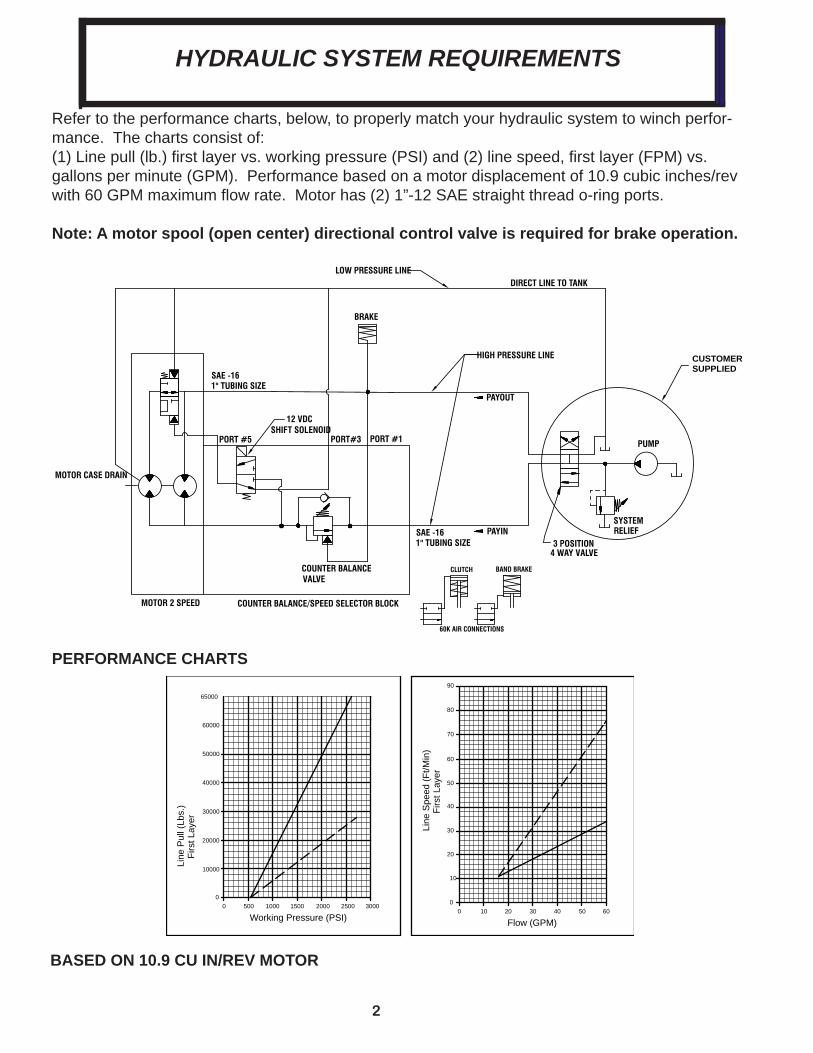
Refer to the performance charts, below, to properly match your hydraulic system to winch perfor-mance. The charts consist of:(1) Line pull (lb.) fi rst layer vs. working pressure (PSI) and (2) line speed, fi rst layer (FPM) vs. gallons per minute (GPM). Performance based on a motor displacement of 10.9 cubic inches/rev with 60 GPM maximum fl ow rate. Motor has (2) 1”-12 SAE straight thread o-ring ports.
Note: A motor spool (open center) directional control valve is required for brake operation.
PORT#3
COUNTER BALANCE/SPEED SELECTOR BLOCK
BRAKE
DIRECT LINE TO TANK
PAYOUT
COUNTER BALANCEVALVE
RELIEF
4 WAY VALVE3 POSITION
SYSTEM
PUMP
CUSTOMERSUPPLIED
MOTOR CASE DRAIN
SAE -16
PORT #1PORT #5
PAYIN
MOTOR 2 SPEED
1" TUBING SIZE
1" TUBING SIZESAE -16
LOW PRESSURE LINE
HIGH PRESSURE LINE
12 VDC SHIFT SOLENOID
60K AIR CONNECTIONS
BAND BRAKECLUTCH
40
50
60
70
30
20
10
010 20 30 40 50 600
0 25002000150010005000
10000
20000
30000
40000
50000
80
90
3000
60000
65000
Line
Spe
ed (F
t/Min
)Fi
rst L
ayer
Flow (GPM)Working Pressure (PSI)
Line
Pul
l (Lb
s.)
Firs
t Lay
er
BASED ON 10.9 CU IN/REV MOTOR
HYDRAULIC SYSTEM REQUIREMENTS
PERFORMANCE CHARTS
3
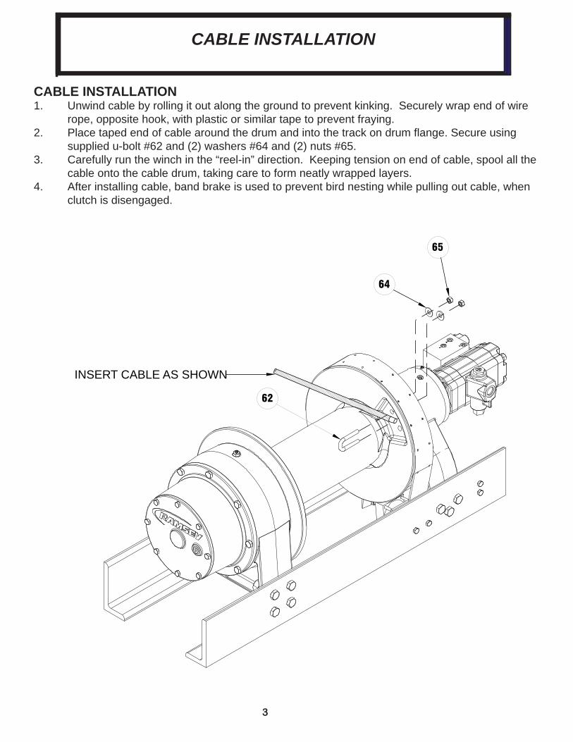
CABLE INSTALLATION1. Unwind cable by rolling it out along the ground to prevent kinking. Securely wrap end of wire rope, opposite hook, with plastic or similar tape to prevent fraying. 2. Place taped end of cable around the drum and into the track on drum fl ange. Secure using supplied u-bolt #62 and (2) washers #64 and (2) nuts #65. 3. Carefully run the winch in the “reel-in” direction. Keeping tension on end of cable, spool all the cable onto the cable drum, taking care to form neatly wrapped layers.4. After installing cable, band brake is used to prevent bird nesting while pulling out cable, when clutch is disengaged.
62
64
65
INSERT CABLE AS SHOWN
CABLE INSTALLATION
4
CLUTCH OPERATION
WARNING: CLUTCH MUST BE FULLY ENGAGED BEFORE STARTING THE WINCHING OPERA-TION.To engage clutch: 1. Move clutch control to engage the clutch.2. Run the motor in the cable out direction until the drum begins to turn.
WARNING: DO NOT DISENGAGE CLUTCH UNDER LOAD. To disengage clutch:1. Run the winch in the “cable out” direction until the load is off the cable.2. Move the clutch control to disengage the clutch. The cable may now be spooled off.
WINCH OPERATIONThe best way to get acquainted with how your winch operates is to make test runs before you use it. Plan your test in advance. Remember, you hear your winch, as well as see it operate; learn to rec-ognize the sounds of a light steady pull, a heavy pull, and sounds caused by load jerking or shifting. Gain confi dence in operating your winch and its use will become second nature with you.The uneven spooling of cable while pulling a load is not a problem, unless there is a cable pileup on one end of drum. If this happens reverse the winch to relieve the load and move your anchor point further to the center of the vehicle. After the job is done you can unspool and rewind for a neat lay of the cable.MAINTENANCEAdhering to the following maintenance schedule will keep your winch in top condition and performing as it should.
Drum bushings are oil impregnated with synthetic oil. The drum bushings do not require additional grease.
A. WEEKLY1. Check the oil level and maintain it to the oil level plug. If oil is leaking out, determine location and repair.2. Check the pressure relief plug on the gear housing cover and the brake housing cover. Be sure they are not plugged. 3. Lubricate cable with light oil.4. Apply a high quality lithium grease to clutch spline. Apply band brake to control drum. Declutch drum and apply grease to spline between clutch and drum. B. MONTHLY1. Check the winch mounting bolts. If any are missing, replace them and securely tighten any that are loose. Use grade 5 or better bolts.2. Inspect the cable. If the cable has become frayed with broken strands, replace immediately.C. ANNUALLY1. Drain the oil from the winch annually or more often if winch is used frequently.2. Refi ll the winch to the oil level plug with all purpose GL-5 oil, (see page 6) or gear lube compat- ible with your climate.3. Inspect winch for damage and wear.
CLUTCH OPERATION
5
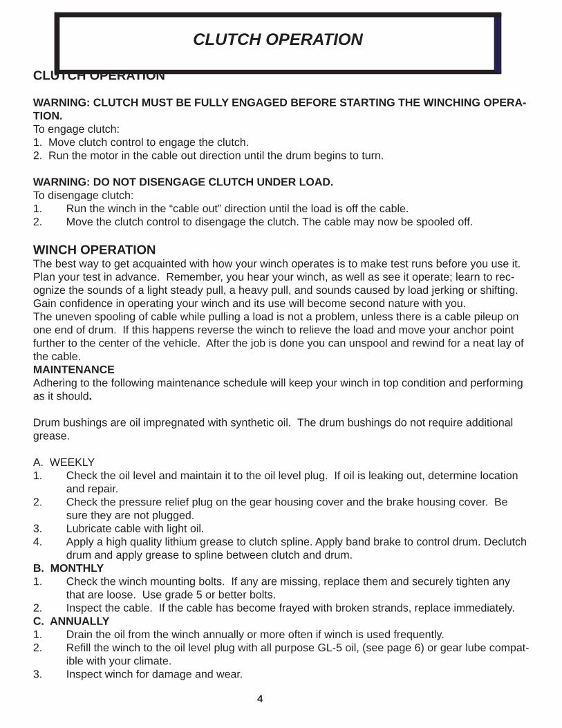
LUBRICATION TABLE
Min Ambient & Opera ng
Max Ambient
Max Opera ng
80W140 Synthe c -25 (-32) 125 (52) 225 (107)75W90 Synthe c -40 (-40) 115 (46) 215 (102)80W90 Conven onal -20 (-29) 100 (38) 180 (82)85W140 Conven onal 20 (6) 120 (50) 200 (93)
Lubricant Descrip on*
Temp Range F(C)
*Use API GL-5 or EP lubricants.
CONDITIONS POSSIBLE CAUSE CORRECTION
OIL LEAKS FROM WINCH 1. Seals damaged or worn.
2. Too much oil.
3. Damaged o-rings.
4. Case drain not connected.
1. Replace seal
2. Drain excess oil. Refer to page 7.
3. Replace o-rings.
4. Connect case drain.
WINCH RUNS TOO SLOW 1. Low flow rate.
2. Hydraulic motor worn out.
1. Check flow rate. Refer to Hydraulic Systems Performance Chart, page 3
2. Replace motor.
CABLE DRUM WILL NOT FREESPOOL
1. Clutch not disengaged 1. Check operation, refer to Clutch Operation, page 5.
BRAKE WLL NOT HOLD 1. Incorrect directional control valve (cylinder spool, closed center).
2. Excessive hydraulic system back pressure.
3. Sprag clutch worn out.
1. Use only a motor spool (open centerdirectional control valve.
2. Reduce system back pressure to lessthan 100 psi.
3. Replace sprag clutch mechanism.
BRAKE WILL NOT RELEASE 1. Brake line disconnected or blocked 1. Repair brake line.
WINCH WILL NOT OPERATE AT HIGH SPEED
1. Shift solenoid not working. 1. Verify shift spool is energized.
WINCH OPERATES ERRATICALLY ON INHAUL
1. Sprag hub is reversed. 1. Install sprag hub correctly.
TROUBLE SHOOTING GUIDE
LUBRICANT CHART andTROUBLE SHOOTING GUIDE
6
55
54
54
44
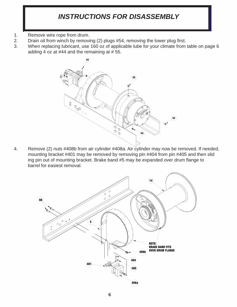
4. Remove (2) nuts #408b from air cylinder #408a. Air cylinder may now be removed. If needed, mounting bracket #401 may be removed by removing pin #404 from pin #405 and then slid ing pin out of mounting bracket. Brake band #5 may be expanded over drum fl ange to barrel for easiest removal.
NOTE: BRAKE BAND FITS OVER DRUM FLANGE
5
14
401
66
408b
408a
405
404
INSTRUCTIONS FOR DISASSEMBLY
1. Remove wire rope from drum.2. Drain oil from winch by removing (2) plugs #54, removing the lower plug fi rst. 3. When replacing lubricant, use 160 oz of applicable lube for your climate from table on page 6 adding 4 oz at #44 and the remaining at # 55.
7
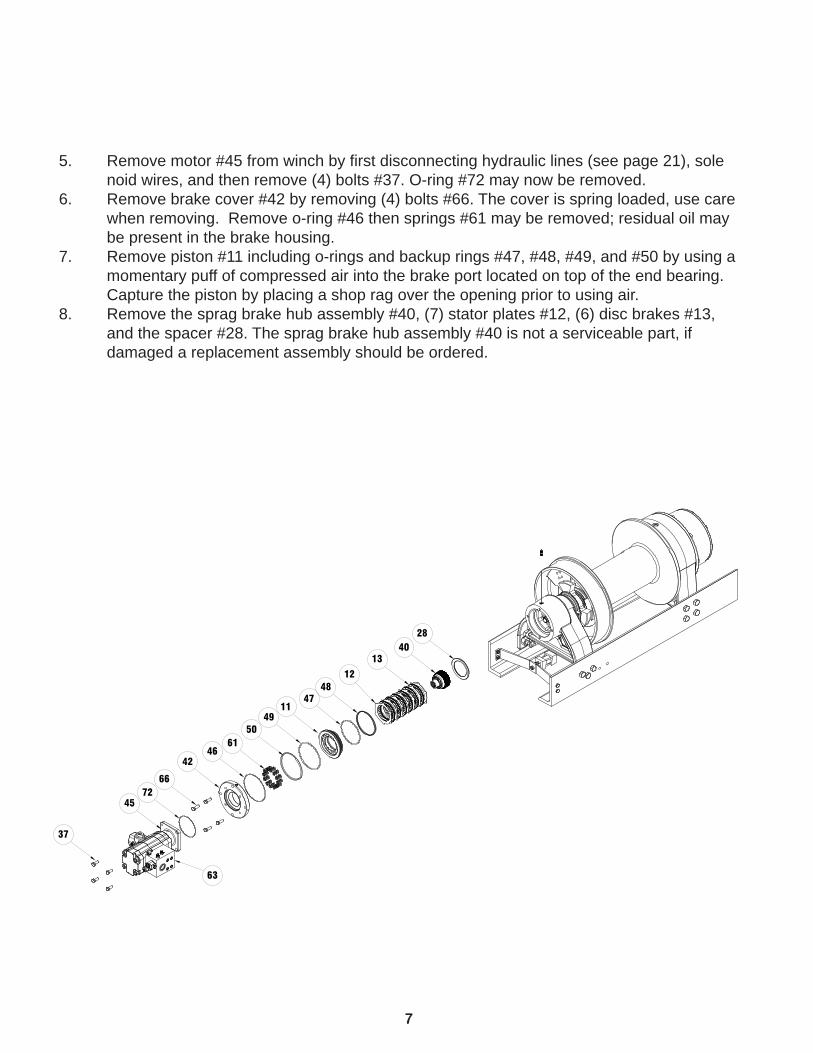
5. Remove motor #45 from winch by fi rst disconnecting hydraulic lines (see page 21), sole noid wires, and then remove (4) bolts #37. O-ring #72 may now be removed. 6. Remove brake cover #42 by removing (4) bolts #66. The cover is spring loaded, use care when removing. Remove o-ring #46 then springs #61 may be removed; residual oil may be present in the brake housing. 7. Remove piston #11 including o-rings and backup rings #47, #48, #49, and #50 by using a momentary puff of compressed air into the brake port located on top of the end bearing. Capture the piston by placing a shop rag over the opening prior to using air.8. Remove the sprag brake hub assembly #40, (7) stator plates #12, (6) disc brakes #13, and the spacer #28. The sprag brake hub assembly #40 is not a serviceable part, if damaged a replacement assembly should be ordered.
4028
12
13
4847
1149
5061
4642
6672
45
37
63
8
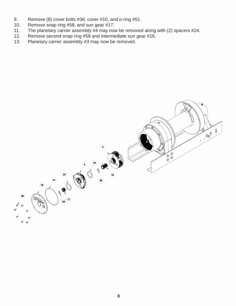
9. Remove (8) cover bolts #36; cover #10, and o-ring #51.10. Remove snap ring #58, and sun gear #17.11. The planetary carrier assembly #4 may now be removed along with (2) spacers #24.12. Remove second snap ring #58 and intermediate sun gear #16.13. Planetary carrier assembly #3 may now be removed.
24
4
36
10
51
24
24
3
16
58
1758
9
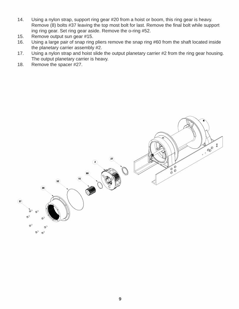
14. Using a nylon strap, support ring gear #20 from a hoist or boom, this ring gear is heavy. Remove (8) bolts #37 leaving the top most bolt for last. Remove the fi nal bolt while support ing ring gear. Set ring gear aside. Remove the o-ring #52.15. Remove output sun gear #15. 16. Using a large pair of snap ring pliers remove the snap ring #60 from the shaft located inside the planetary carrier assembly #2. 17. Using a nylon strap and hoist slide the output planetary carrier #2 from the ring gear housing. The output planetary carrier is heavy.18. Remove the spacer #27.
52
20
37
15
60
227
10
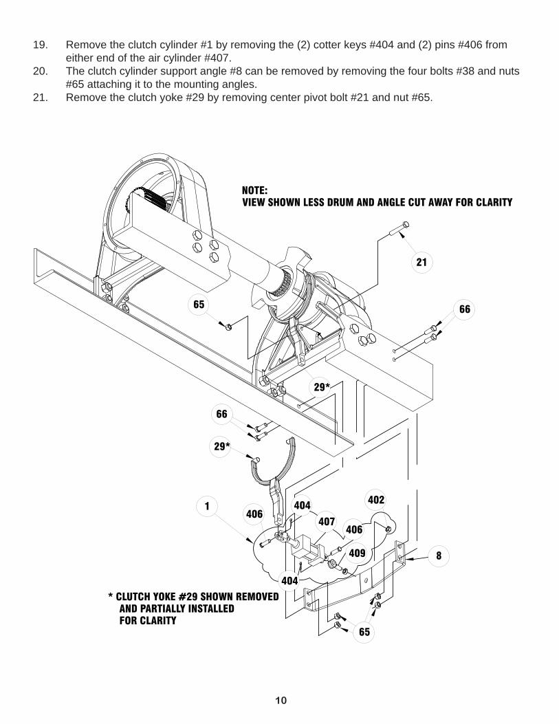
19. Remove the clutch cylinder #1 by removing the (2) cotter keys #404 and (2) pins #406 from either end of the air cylinder #407.20. The clutch cylinder support angle #8 can be removed by removing the four bolts #38 and nuts #65 attaching it to the mounting angles.21. Remove the clutch yoke #29 by removing center pivot bolt #21 and nut #65.
8
29*
65
21
NOTE: VIEW SHOWN LESS DRUM AND ANGLE CUT AWAY FOR CLARITY
65
66
29*
1
66
* CLUTCH YOKE #29 SHOWN REMOVED AND PARTIALLY INSTALLED FOR CLARITY
402406
407
404
406
404
409
11
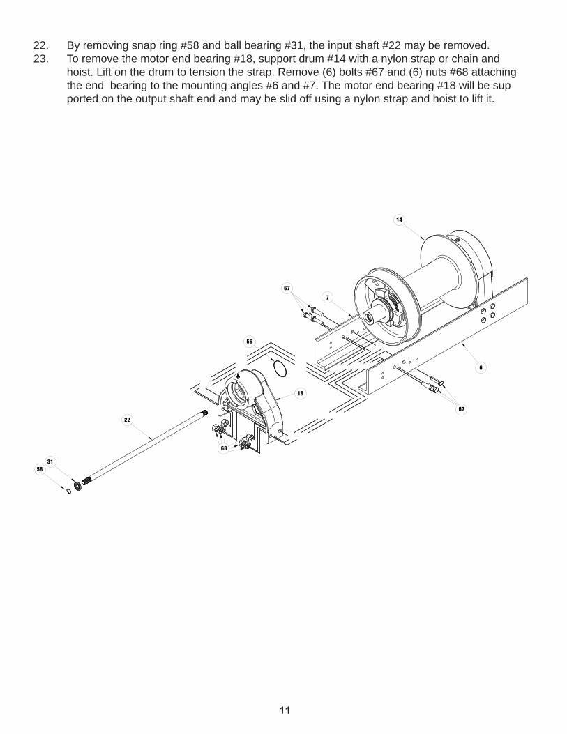
22. By removing snap ring #58 and ball bearing #31, the input shaft #22 may be removed. 23. To remove the motor end bearing #18, support drum #14 with a nylon strap or chain and hoist. Lift on the drum to tension the strap. Remove (6) bolts #67 and (6) nuts #68 attaching the end bearing to the mounting angles #6 and #7. The motor end bearing #18 will be sup ported on the output shaft end and may be slid off using a nylon strap and hoist to lift it.
67
68
18
22
3158
7
14
67
6
56
12
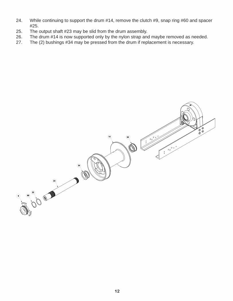
24. While continuing to support the drum #14, remove the clutch #9, snap ring #60 and spacer #25. 25. The output shaft #23 may be slid from the drum assembly. 26. The drum #14 is now supported only by the nylon strap and maybe removed as needed. 27. The (2) bushings #34 may be pressed from the drum if replacement is necessary.
14
34
23
25
60 9
34
13
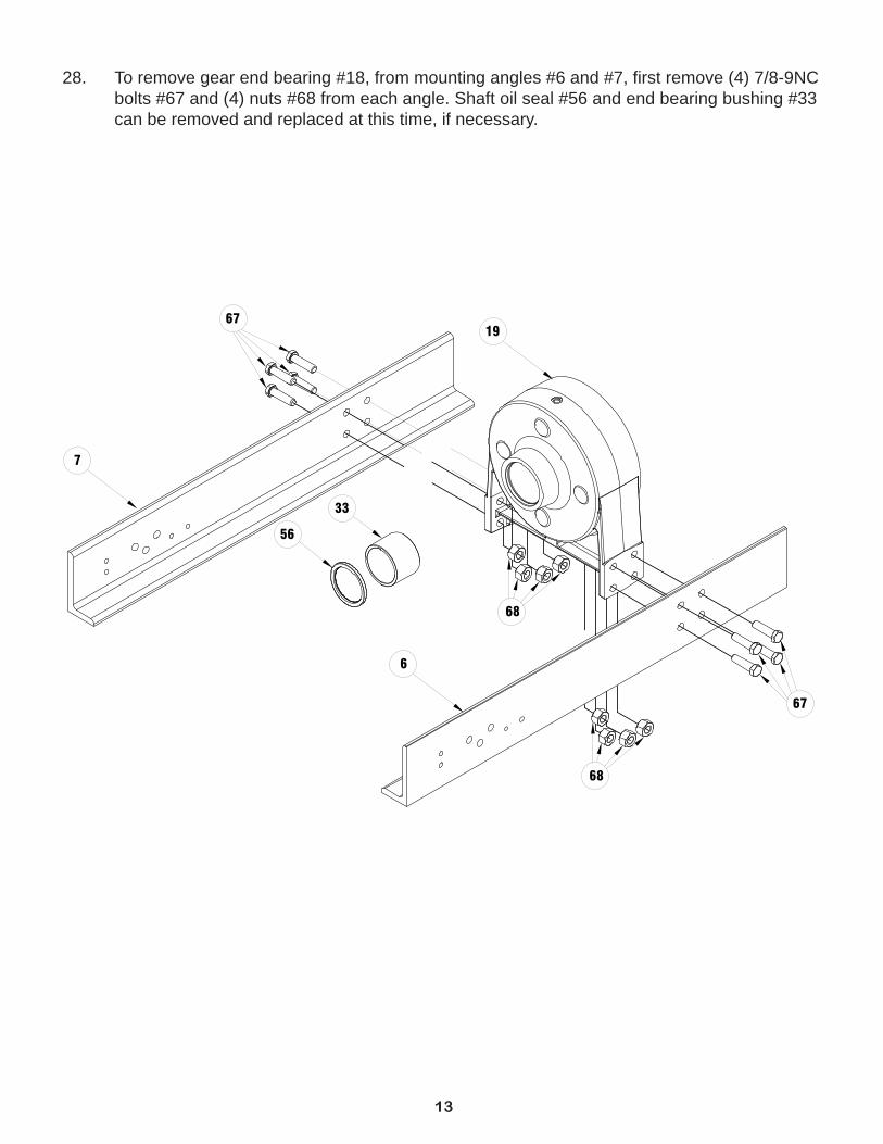
28. To remove gear end bearing #18, from mounting angles #6 and #7, fi rst remove (4) 7/8-9NC bolts #67 and (4) nuts #68 from each angle. Shaft oil seal #56 and end bearing bushing #33 can be removed and replaced at this time, if necessary.
6719
33
56
67
7
6
68
68
14
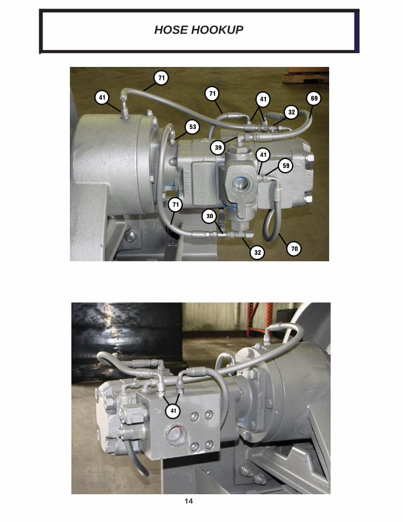
71
41
53
71 41
32
69
41
59
71
30
32 70
39
HOSE HOOKUP

15
NOTES
16
4455 19
27
260
1552 20
373
16
458
1758 24 51
3654
10
5468
3356
5
67
6
3414
62
6465
3423
2560
922
21
5729
1
8
3518
766 67 37 37
63
45
44
6111 47
4813 12 28
58
31
40
495046426672
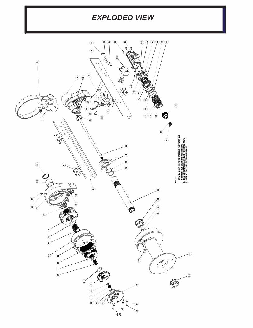
NOTE
S:
1. I
TEM
1 -
AIR
CYLI
NDER
KIT
CON
TAIN
S FA
STEN
ERS
AND
C
YLIN
DERS
FOR
CLU
TCH
AND
BAN
D BR
AKE.
2. I
TEM
63
CONT
AINS
FAS
TENE
RS F
OR B
RAKE
VAL
VE.
3. H
OSE
KIT
CONT
AINS
FIT
TING
S AN
D H
OSE.
6865
1
24
74
65
EXPLODED VIEW
17
ITE
M
QT
YP
ART
NO
DE
SC
RIP
TIO
NIT
EM
Q
TY
PAR
T N
OD
ES
CR
IPT
ION
11
2561
31A
IR C
YLI
ND
ER
38
NO
T U
SE
D2
125
1314
OU
TP
UT
CA
RR
IER
AS
SE
MB
LY39
143
2018
FIT
TIN
G J
IC O
-RIN
G E
L3
129
6758
INT
ER
ME
DIA
TE
CA
RR
IER
AS
SE
MB
LY40
129
6952
SP
RA
G B
RA
KE
HU
B A
SS
EM
BLY
41
2967
57IN
PU
T C
AR
RIE
R A
SS
EM
BLY
414
4320
23F
ITT
ING
JIC
O-R
ING
NIP
PLE
51
2997
49B
AN
D B
RA
KE
421
4380
43B
RA
KE
CO
VE
R6
130
3146
LH M
OU
NT
ING
AN
GLE
437
130
3147
RH
MO
UN
TIN
G A
NG
LE44
245
6008
FIT
TIN
G-R
ELI
EF
1/8-
27N
PT
F, 1
5 P
SI M
AX
81
3125
78C
LUT
CH
CY
LIN
DE
R S
UP
PO
RT
BR
AC
KE
T45
145
8215
MO
TO
R-H
YD
91
3245
09C
LUT
CH
461
4620
63O
-RIN
G 2
-165
101
3281
72G
EA
R H
OU
SIN
G C
OV
ER
471
4620
82O
-RIN
G 2
-358
111
3300
16B
RA
KE
PIS
TO
N48
146
2083
BA
CK
UP
RIN
G12
733
0017
ST
AT
OR
PLA
TE
491
4620
84O
-RIN
G 2
-362
136
3300
18D
ISC
-BR
AK
E50
146
2085
BA
CK
UP
RIN
G14
133
2238
DR
UM
511
4620
90O
-RIN
G 2
-270
151
3342
17G
EA
R-S
UN
OU
TP
UT
521
4620
89O
-RIN
G 2
-279
161
3342
20G
EA
R-S
UN
INT
ER
ME
DIA
TE
531
4320
53F
ITT
ING
JIC
O-R
ING
NIP
PLE
171
3342
45G
EA
R-S
UN
INP
UT
542
4680
41P
LUG
, -8
SA
E, 3
/4"-
16 U
NF
181
3383
78E
ND
BE
AR
ING
-MO
TO
R S
IDE
551
4680
42R
ED
UC
ER
-3/4
-16
SA
E O
-RIN
G X
1/8
NP
TF
191
3383
89E
ND
BE
AR
ING
-GE
AR
SID
E56
148
6094
SE
AL-
OIL
-SH
AF
T20
133
8390
HO
US
ING
-GE
AR
571
4860
95S
EA
L-O
IL-S
HA
FT
211
4145
43C
AP
SC
RE
W-1
/2-1
3NC
X3L
G,H
XH
D, G
R 5
583
4900
06S
NA
P R
ING
510
0-12
522
135
7186
INP
UT
SH
AF
T59
143
2054
FIT
TIN
G J
IC S
WIV
EL
EL
231
3571
87S
HA
FT
-OU
TP
UT
602
4900
62S
NA
P R
ING
510
0-37
524
236
2301
SP
AC
ER
6112
4941
29S
PR
ING
-BR
AK
E25
136
2311
SP
AC
ER
-SH
AF
T62
151
4021
U-B
OLT
26N
OT
US
ED
631
5160
48C
OU
NT
ER
BA
LAN
CE
BLO
CK
271
3623
12S
PA
CE
R64
241
8223
FLA
TW
AS
HE
R 1
/228
136
2305
SP
AC
ER
657
4180
69N
UT
-1/2
-13N
C H
EX
RE
G,Z
/P29
137
0062
YO
KE
-SH
IFT
ER
668
4145
40C
AP
SC
RE
W-1
/2-1
3NC
X 2
LG
HX
HD
GR
.5
301
4320
48F
ITT
ING
JIC
SW
IVE
L T
EE
6714
4147
90B
OLT
-7/8
-9N
C X
3.2
5 LG
,HX
HD
,GR
8,P
LAT
ED
311
4021
32B
ALL
BE
AR
ING
6814
4181
08N
UT
-7/8
-9N
C H
EX
RE
G Z
/P32
243
2049
FIT
TIN
G J
IC B
RA
NC
H T
EE
691
5091
37H
OS
E33
141
2135
EN
D B
EA
RIN
G B
US
HIN
G70
250
9140
HO
SE
342
4121
61D
RU
M B
US
HIN
G71
350
9141
HO
SE
351
4121
36E
ND
BE
AR
ING
BU
SH
ING
721
4620
81O
RIN
G 2
-159
368
4142
77C
AP
SC
RE
W-3
/8-1
6NC
X1L
G H
XH
D G
R 5
73N
OT
US
ED
3714
4145
78C
AP
SC
RE
W-1
/2-1
3NC
X1
1/4,
HX
HD
,GR
5,ZP
741
4680
16P
IPE
PLU
G 1
/8-2
7NP
TF
NO
T U
SE
D
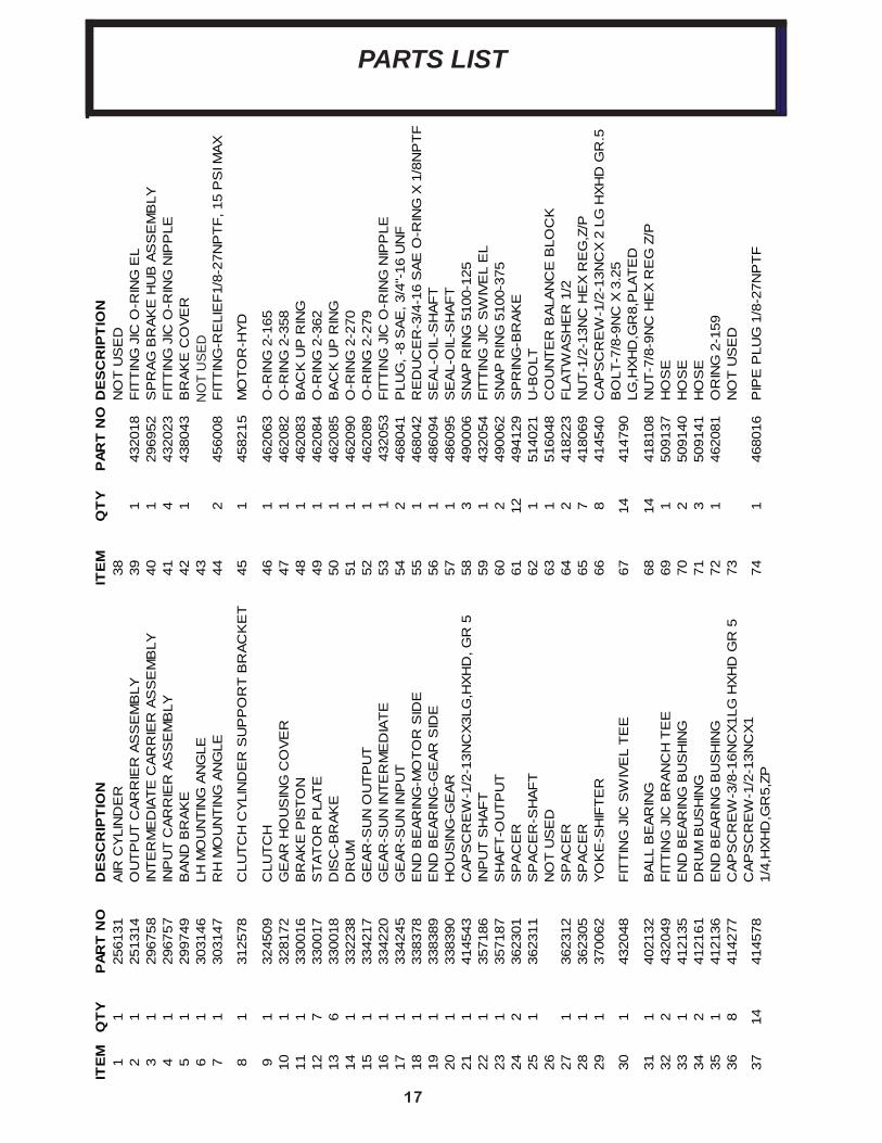
PARTS LIST
18
402
402
409
403
404
406
404
401
405
404
406
403
407
408
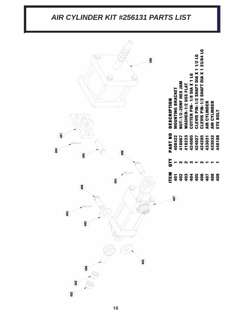
ITE
M
ITE
M
QTY
QTY
PA
RT N
OP
AR
T N
OD
ES
CR
IPTIO
ND
ES
CR
IPTIO
N401
1408422
MO
UN
TIN
G B
RAC
KET
402
2418067
NU
T-1/2
-20N
F H
EX J
AM
403
2418223
WASH
ER
-1/2
USS F
LAT
404
3424005
CO
TTER
PIN
- 1/8
DIA
X 1
LG
405
1424027
CLE
VIS
PIN
-1/2
SH
AFT
DIA
X 1
1/2
LG
406
2424205
CLE
VIS
PIN
-1/2
SH
AFT
DIA
X 1
23/6
4 L
G407
1433031
AIR
CYLI
ND
ER
408
1433032
AIR
CYLI
ND
ER
409
1448108
EYE B
OLT
AIR CYLINDER KIT #256131 PARTS LIST
19
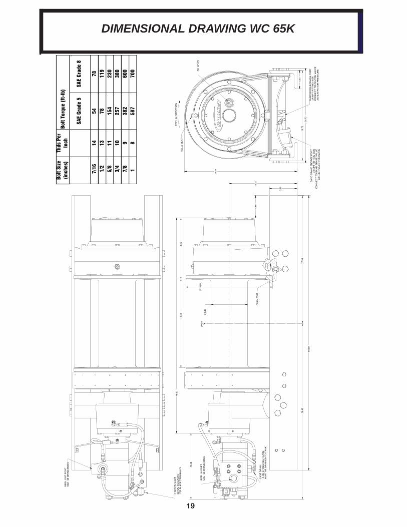
Bo
lt Si
ze
(inc
hes)
Thds
Per
In
ch
SAE
Grad
e 5
SAE
Grad
e 8
7/1
614
5478
1/2
13
7811
9 5
/8
1115
423
0 3
/4
1025
738
0 7
/8
938
260
01
858
770
0
Bolt
Torq
ue (f
t-lb
)
DIMENSIONAL DRAWING WC 65K
14.
75
6.0
0
4.8
9
60.
00
8.
00
19
.00
19.
38
13.
36
46.
97
14.
50
27.
94
38.
42
DRU
MC L
DRA
IN P
ORT
RE
EL
IN P
OR
TS
AE
-16
OR
ING
BO
SS
CA
SE
DR
AIN
-4
JIC
37
DE
GR
EE
FLA
RE
MU
ST
BE
DR
AIN
ED
TO
TA
NK
RE
EL
OU
T P
OR
TS
AE
-16
OR
ING
BO
SS
2 S
PE
ED
SH
IFT
12V
DC
SO
LEN
OID
.250
BLA
DE
TE
RM
INA
LS
19.
75
20.
72
24.
50
4.0
0
RE
EL
IN D
IRE
CTI
ON
FILL
& V
EN
T
OIL
LE
VE
L
BA
ND
BR
AK
E E
NG
AG
E P
OR
T1/
4 N
PT
FITT
ING
SIZ
EC
ON
NE
CT
TO B
AN
D B
RA
KE
VA
LVE
100-
130
PS
I AIR
PR
ES
SU
RE
CLU
TCH
DIS
-EN
GA
GE
PO
RT
1/8
NP
T FI
TTIN
G S
IZE
CO
NN
EC
T TO
CLU
TCH
VA
LVE
100-
130
PS
I AIR
PR
ES
SU
RE
Limited Warranty RAMSEY WINCH warrants each new RAMSEY Wildcat Winch to be free from defects in material and workmanship for a period of two (2) years from the date of purchase. Our new two year limited warranty is standard equipment on all Wildcat Winches manufactured after July 4th, 2014, and is also available for all Wildcat series winches currently in inventory at authorized distributors if the model and serial numbers are submitted to Ramsey Winch by August 30, 2014. End users who have purchased a winch since June 1, 2014, are also eligible for the two year warranty with purchase date, serial number, and model number submitted to an approved Wildcat Distributor by August 30, 2014.
Warranty General. The obligation under this warranty, statutory or otherwise, is limited to the replacement or repair at the Manufacturer's factory, or at a point designated by the Manufacturer, of such part that shall appear to the Manufacturer, upon inspection of such part, to have been defective in material or workmanship. This warranty does not obligate RAMSEY WINCH to bear the cost of labor or transportation charges in connection with the replacement or repair of defective parts, nor shall it apply to a product upon which repairs or alterations have been made unless authorized by the Manufacturer, or for equipment misused, neglected or which has not been installed correctly.
To the fullest extent permitted by applicable law, the following are hereby excluded and disclaimed: 1.All warranties of fitness for a particular purpose; 2. All warranties of merchantability; 3. All claims for consequential or incidental damages. There are no warranties that extend beyond the description that appears on the face hereof. Some states do not allow the above exclusions or disclaimers in consumer transactions and as such this disclaimer/exclusion may not apply to your particular case. To the extent such warranties of fitness for a particular purpose or merchantability are deemed to apply to this product, they exist for only so long as the express limited warranty elsewhere set forth is in existence.
RAMSEY WINCH whose policy is one of continuous improvement, reserves the right to improve its products through changes in design or materials as it may deem desirable without being obligated to incorporate such changes in products of prior manufacture.
If field service at the request of the Buyer is rendered and the fault is found not to be with RAMSEY WINCH's product, the Buyer shall pay the time and expense of the field representative. Bills for service, labor or other expenses that have been incurred by the Buyer without approval or authorization by RAMSEY WINCH will not be accepted.
This Warranty gives you specific legal rights and you may also have other legal rights, which vary from state to state.


Ramsey Winch CompanyPost Offi ce Box 581510
Tulsa, Oklahoma 74158-1510Telephone: (#918) 438-2760 FAX: (#918) 438-6688
![BUILDING PREMIUM BRAND - GMC MEDIA · 2016. 8. 29. · Magazine 65k / month 65K/ month Website 2,500K UV / month Marie Claire TV. ... June 2016 Lifestyles - Beauty/Fashion/Style [Undup.]](https://img.pdfslide.net/doc/110x75/5fee5f046aefa00c442c538c/building-premium-brand-gmc-2016-8-29-magazine-65k-month-65k-month-website.jpg)