Embed Size (px)
Citation preview

WILSON AMERICAN PRECISION®
PRESS BRAKE SOLUTIONS
Standards, Specials and Accessories

32 3.75” Acute Punch - 30º33 5.75” Acute Punch - 30º34 3.75” Large Gooseneck Punch 75º35 3.75” Large Gooseneck Punch 90º, 88º 36 5.75” Large Gooseneck Punch - 75º37 5.75” Large Gooseneck Punch - 90º, 88º38 3.75” Sash Punch - 75º39 3.75” Sash Punch - 90º, 88º40 5.75” Sash Punch - 75º41 5.75” Sash Punch - 90º, 88º42 3.75” Arrow Punch - 90º, 88º, 75º43 3.75” & 5.75 Block Punch 88º, 85º, 75º44 8.75” Large Gooseneck Punch - 90º, 88º, 75º45 8.75” Sash Punch - 90º, 88º, 75º46 8.75” Acute Punch - 30º
6 American Style Tooling8 Acute Block Punch - 3.75” 8 Acute Gooseneck Punch - 5.75” 9 Arrow Punch - 3.75” 10 Large Gooseneck Punch - 3.75” 11 Large Gooseneck Punch - 5.75” 12 Sash Gooseneck Punch - 3.75” 13 Sash Gooseneck Punch - 5.75” 14 Block Punch - 3.75”, 5.75”15 Sash / Acute Gooseneck Punch - 8.75” 16 Large Gooseneck Punch - 8.75”16 Letter Stamp17 Large Radius Holder and Tip Assembly
6PUNCH
32BEND LIMIT GRAPHS
31BENDING THICKMATERIALS
Content18DIE
18 V-Series Black20 Urethane Die22 Stage Acute Die22 Stage Block Die23 Stage Arrow Die23 Large V Die 24 Urethane Pads and Holders
21STAGE BENDING
25 Offset Tool26 Flattening Blocks26 Thrust Absorbing Flattening Die26 Two Stage Hemming 27 Replacement V Blocks28 Punch Holder30 Die Holder
25SETS & HOLDERS

66 Hand Tools67 Measuring Tools67 Urethane 100’ Roll68 Tool Storage Cabinets
69 Tip Modifications69 Ear Piece70 Tonnage Estimates71 Specials Checklist73 Air Bending Force Charts
48 Custom Hemming 50 Offset Tools51 Adjustable Dies51 Replaceable Shoulder Die52 Large Radii Applications53 Strengthening Rib, V Rib54 Forming Applications54 Open Hat54 Window Application54 Rod Bending55 Stamping Application56 Channel Applications58 Curl Tool Set59 Center Curl Application59 Double Decker Tool Set60 Special Punch Shapes61 Holders62 Wiping and Rotary Bending63 Deep Box Bending63 Swing Ear Sections64 Turret Adapter65 C-Frame Tooling
47SPECIALS 66ACCESSORIES
69REFERENCE
© 2016 Wilson Tool International
Prices and product availability are subject to change without notice.
4 WILSONTOOL.COM
THE WILSON TOOL DIFFERENCE
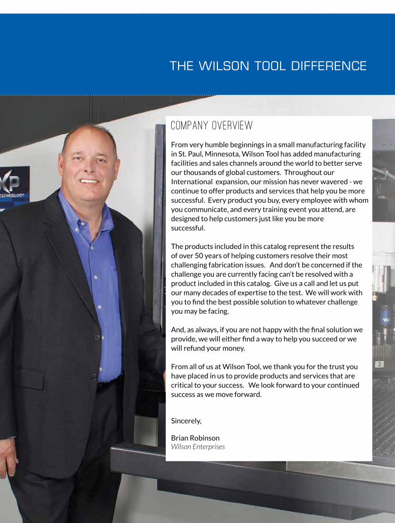
Company Overview
From very humble beginnings in a small manufacturing facility in St. Paul, Minnesota, Wilson Tool has added manufacturing facilities and sales channels around the world to better serve our thousands of global customers. Throughout our International expansion, our mission has never wavered - we continue to offer products and services that help you be more successful. Every product you buy, every employee with whom you communicate, and every training event you attend, are designed to help customers just like you be more successful.
The products included in this catalog represent the results of over 50 years of helping customers resolve their most challenging fabrication issues. And don’t be concerned if the challenge you are currently facing can’t be resolved with a product included in this catalog. Give us a call and let us put our many decades of expertise to the test. We will work with you to find the best possible solution to whatever challenge you may be facing.
And, as always, if you are not happy with the final solution we provide, we will either find a way to help you succeed or we will refund your money.
From all of us at Wilson Tool, we thank you for the trust you have placed in us to provide products and services that are critical to your success. We look forward to your continued success as we move forward.
Sincerely,
Brian RobinsonWilson Enterprises

5WILSONTOOL.COM
PUNCH ING
ACCESSOR IES
BEND ING
STAMP ING
The Wilson Tool Punching Division continues to drive the industry with new levels of quality, delivery service and innovation.
From the early days of Series 80 tooling to Wilson Wheels to innovative EXP technology, our punching division has been the leading innovation driver in the industry. When combined with the most experienced customer support professionals in the industry, the solutions offered from Wilson Tool continue to raise the bar on performance and innovation. Thick turret, Trumpf, Salvagnini, or any other style of punch press you may be using, Wilson Tool offers the most complete line of tooling solutions available today.
Wilson Tool’s Bending Division delivers the most complete line of tooling and clamping solutions available anywhere. Period. Whether you use American, European, or Wila/Trumpf style precision tooling or conventional style tooling, Wilson Tool has a solution for you. Our clamping options cover these styles as well. With hydraulic push button options, quick release mechanical options, or standard manual clamps, Wilson Tool has a clamping solution for any style of machine or budget. And our custom tooling manufacturing capabilities have quickly become the envy of the industry with innovative solutions for very complex bending challenges. And with manufacturing facilities located in the USA and Canada, our delivery times to North American fabricators are the fastest in the industry.
Whether you need tooling storage systems, urethane rolls, hand tools or other types of related supplies, our accessory products offer a wide range of solutions to help you be more productive.
From small to large items, our accessories will help your shop be more organized and efficient.
Wilson Tool’s Stamping division (aka Impax Tooling Solutions) offers high quality punch and die components for the stamping industry. Innovative products such as our Accu-Lock retainer inserts, and extensive coating options combined with our world-class customer service have enabled us to quickly grow into a world-class provider. With a direct sales force throughout North America, we deliver products straight from the factory to you, enabling the fastest deliveries in the industry. Our custom tooling expertise is second to none with many customers coming to us for their most difficult stamping challenges.

6 WILSONTOOL.COM WILSONTOOL.COM
AMERICAN PRECISION PRESS BRAKE TOOLING
• Tools can be loaded by a single operator.• Easy to store. • Sectionalized tools come in ten different lengths.• Most sectionalized punches include two ear pieces (horns).• Heat treat options include Nitrex® and laser hardening• Each tool laser marked with significant information.• Special tooling available. Contact the application sales desk.• Lengths longer than 36" (914.4mm) available.
PRECISION MANUFACTURED FOR CONSISTENT RESULTS.Wilson American Precision press brake tooling is precision manufactured to a tolerance of +/- .0008" (.02mm) on all critical dimensions to achieve the same precision and quality associated with European style press brake tooling. Available long (36"/914.4mm), short (18"/457.2mm) and sectionalized (35.87"/911.2mm) tooling can be mixed and matched for consistent bending quality throughout multiple jobs.
PUSH BUTTON TECHNOLOGYLoad and unload tools instantly with Wilson Tool’s unique click-in feature. Wilson’s patented push button technology eliminates the need for special clamps, holders or dedicated upper beams, significantly reducing costly downtime.
STAGE TOOLINGAchieve maximum tool change over efficiency by reducing set ups and making a complete part in one handling. See page 21 for additional details.
SWING EAR SECTIONS
Box bending with return flanges.
Ear(s) will recess/fall in left to right .500” - .750” (not to be confused with vertical movement.)
There will be approximately 1.0” - 1.5” of relief to rotate and drop the finished part.
See page 63 for additional information.
See this tool in action on the Wilson Tool YouTube Channel
Left and right ear sections shown in illustration.
AMERICAN PRECISION TOOLING FEATURES:

7WILSONTOOL.COM WILSONTOOL.COM
AMERICAN PRECISION PRESS BRAKE TOOLING
Upper Beam/Clamp
Punch
ATTENTION: Upper beam/clamp opening should not exceed .531" [13.5mm]. Exceeding specified opening on upper beam/clamp opening may result in release of punch.
.625[15.9].500[12.7]
.687[17.5]
.625[15.9].500[12.7]
.750[19.1] .687
[17.5]
.625[15.9].500[12.7]
.531.531.531
Straight TangPush Button Safety Tang
.625[15.9].500[12.7]
.687[17.5]
.625[15.9].500[12.7]
.750[19.1] .687
[17.5]
.625[15.9].500[12.7]
.531.531.531
Straight TangBolt-on Solid Safety Tang
(Standard on all long punches)
.625[15.9].500[12.7]
.687[17.5]
.625[15.9].500[12.7]
.750[19.1] .687
[17.5]
.625[15.9].500[12.7]
.531.531.531
Groove (G) TangPush Button Safety Tang
Inch[mm]
4.0[101.6]
.3.0[76.2]
8.0[203.2]
4.0[101.6]
.625[15.9]
.75[19.1]
1.0[25.4]
12[304.8]
.5[12.7]
2.0[50.8]
Inch[mm]
4.0[101.6]
.3.0[76.2]
8.0[203.2]
4.0[101.6]
.625[15.9]
.75[19.1]
1.0[25.4]
12[304.8]
.5[12.7]
2.0[50.8]
STANDARD PUNCH SECTION LENGTHS
STANDARD DIE SECTION LENGTHS
SHORT (S) 18" [457.2mm] LONG (L) 36" [914.4mm] SECTIONALIZED (X) 35.875" [911.2mm]
PUSH BUTTON COMPONENTS
CAT. NO. DESCRIPTION
50071 A Push button for .625 C/L order spring 814050072 B Push button for .687 C/L order spring 814050073 C Push button for .750 C/L order spring 814150074 D Push button for .875 C/L order spring 814150075 E Push button for 1.000 C/L order spring 814150076 F Push button for 1.250 C/L order spring 8141
50077 G Push button for 1.500 C/L order spring 8141
50078 H Push button for 1.875 C/L order spring 8141
8140 Spring Ø.375 X .300 in length
8141 Spring Ø.360 X .438 in length
50079 Logo plug - blue
51083 Safety hookA B C D E GF H
SPRING
PUSH BUTTON
SAFETY HOOK
LOGO PLUG

8 WILSONTOOL.COM WILSONTOOL.COM
30º PUNCH
3.75" ACUTE BLOCK
5.75" ACUTE GOOSENECK
Note: Sectionalized version does not include ear pieces (horns). Ear pieces (horns) available at an additional cost.
5.75" TALL ONLYEar pieces (horns)
1.250[31.8]
H
RA
1.250[31.8]
RA
H
1.750[44.5]
R.375[9.5]
.750[19.1]
1.250[31.8]
Ref. only
5.75" ACUTE GOOSENECK PUNCH
CAT. NO..A
Angle
R Tip Radius inch [mm]
H Height inch [
Max Ton/ft=
Bu
tto
n PRICE
Straight Groove L&S X L 36”
S 18”
X 35.87”
50209 50209G30˚
.031 [0.8] 5.661 [143.8] 3030
ABend Limit
Graph page 33
50221 50221G .062 [1.6] 5.571 [141.5]40
A50227 50227G .125 [3.2] 5.392 [137.0] A
Approximate Gross Weight [lbs.], unboxed 42 21 38
All tonnages are based on direct load and do not apply for thrusting applications.
3.75" ACUTE BLOCK PUNCH
CAT. NO.A
Angle
R Tip Radius inch [mm]
H Height
inch [mm]
Max Ton/ft=
Bu
tto
n PRICE
Straight Groove L&S X L 36”
S 18”
X 35.87”
50045 50045G30˚
.031 [0.8] 3.661 [93.0] 3030
ABend Limit
Graph page 32
50046 50046G .062 [1.6] 3.571 [90.7]40
A50047 50047G .125 [3.2] 3.392 [86.2] A
Approximate Gross Weight [lbs.], unboxed 35 18 35
A B C D E GF H
A B C D E GF H
PUNCH
9WILSONTOOL.COM WILSONTOOL.COM
ARROW PUNCH
Ref. only
1.250[31.8]
H
R
.500[12.7]
A
1.500[38.1]
R.375[9.5]
.500[12.7]
1.250[31.8]
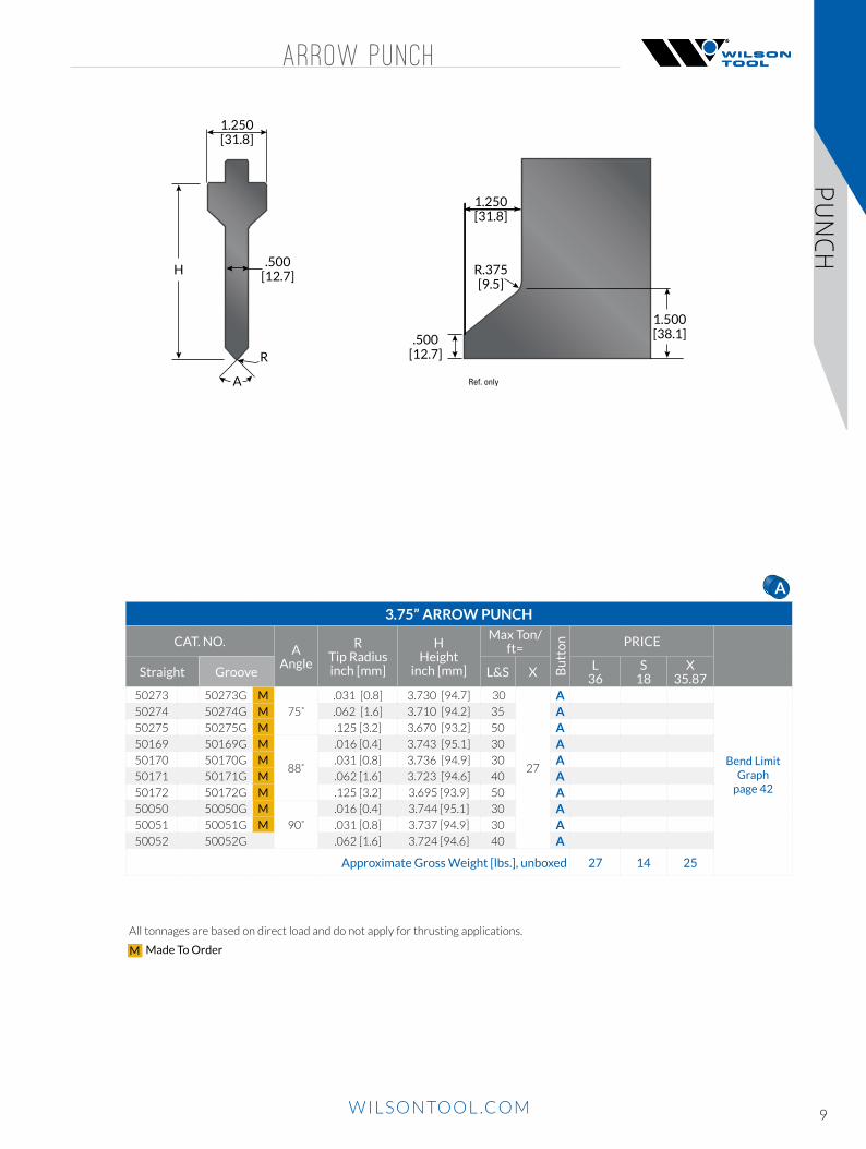
3.75” ARROW PUNCH
CAT. NO.A
Angle
R Tip Radius inch [mm]
H Height
inch [mm]
Max Ton/ft=
Bu
tto
n PRICE
Straight Groove L&S X L 36
S 18
X 35.87
50273 50273G M
75˚
.031 [0.8] 3.730 [94.7] 30
27
A
Bend Limit Graph
page 42
50274 50274G M .062 [1.6] 3.710 [94.2] 35 A50275 50275G M .125 [3.2] 3.670 [93.2] 50 A50169 50169G M
88˚
.016 [0.4] 3.743 [95.1] 30 A50170 50170G M .031 [0.8] 3.736 [94.9] 30 A50171 50171G M .062 [1.6] 3.723 [94.6] 40 A50172 50172G M .125 [3.2] 3.695 [93.9] 50 A50050 50050G M
90˚
.016 [0.4] 3.744 [95.1] 30 A50051 50051G M .031 [0.8] 3.737 [94.9] 30 A50052 50052G .062 [1.6] 3.724 [94.6] 40 A
Approximate Gross Weight [lbs.], unboxed 27 14 25
A B C D E GF H
PUNCH
All tonnages are based on direct load and do not apply for thrusting applications.
Made To OrderM
10 WILSONTOOL.COM WILSONTOOL.COM
3 .75 ” LARGE GOOSENECK PUNCH
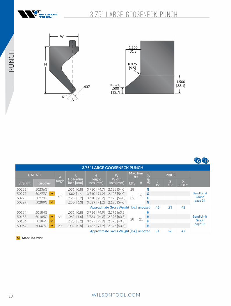
3.75" LARGE GOOSENECK PUNCH
CAT. NO.A
Angle
R Tip Radius inch [mm]
H Height
inch [mm]
W Width
inch [mm]
Max Ton/ft=
Bu
tto
n PRICE
Straight Groove L&S X L 36”
S 18”
X 35.87”
50236 50236G
75˚
.031 [0.8] 3.730 [94.7] 2.125 [54.0] 28
21
GBend Limit
Graph page 34
50277 50277G M .062 [1.6] 3.710 [94.2] 2.125 [54.0]35
G50278 50278G .125 [3.2] 3.670 [93.2] 2.125 [54.0] G50289 50289G M .250 [6.3] 3.589 [91.2] 2.125 [54.0] G
Approximate Gross Weight [lbs.], unboxed 46 23 42
50184 50184G
88˚
.031 [0.8] 3.736 [94.9] 2.375 [60.3]
28 21
HBend Limit
Graph page 35
50185 50185G M .062 [1.6] 3.723 [94.6] 2.375 [60.3] H50186 50186G M .125 [3.2] 3.695 [93.9] 2.375 [60.3] H
50067 50067G M 90˚ .031 [0.8] 3.737 [94.9] 2.375 [60.3] H
Approximate Gross Weight [lbs.], unboxed 51 26 47
W
H
R
.437
A
1.500[38.1]
R.375[9.5]
.500[12.7]
1.250[31.8]
Ref. only
A B C D E GF H
PUNCH
Made To OrderM

11WILSONTOOL.COM WILSONTOOL.COM
5 .75 ” LARGE GOOSENECK PUNCH
5.75" LARGE GOOSENECK PUNCH
CAT. NO.A
Angle
R Tip Radius inch [mm]
H Height
inch [mm]
W Width
inch [mm]
Max Ton/ft=
Bu
tto
n PRICE
Straight Groove L&S X L 36”
S 18”
X 35.87”
50248 50248G
75˚
.031 [0.8] 5.730 [145.5] 2.125 [54.0]
35 21
G
Bend Limit Graph
page 36
50249 50249G .062 [1.6] 5.710 [145.0] 2.125 [54.0] G50250 50250G .125 [3.2] 5.670 [144.0] 2.125 [54.0] G50266 50266G .250 [6.3] 5.589 [141.0] 2.125 [54.0] G
Approximate Gross Weight [lbs.], unboxed 68 34 62
50208 50208G
88˚
.016 [0.4] 5.743 [145.9] 2.500 [63.5]
24 18
H
Bend Limit Graph
page 37
50220 50220G .031 [0.8] 5.736 [145.7] 2.500 [63.5] H50226 50226G M .062 [1.6] 5.723 [145.4] 2.500 [63.5] H50232 50232G M .125 [3.2] 5.695 [144.7] 2.500 [63.5] H50219 M 50219G M 90˚ .031 [0.8] 5.737 [145.7] 2.500 [63.5] H
Approximate Gross Weight [lbs.], unboxed 77 39 70
H
RA
.437
W
R.375[9.5]
.500[12.7]
1.250[31.8]
1.500[38.1]
A B C D E GF H
All tonnages are based on direct load and do not apply for thrusting applications.
PUNCH
Made To OrderM

12 WILSONTOOL.COM WILSONTOOL.COM
3 .75 ” SASH GOOSENECK PUNCH
3.75" SASH GOOSENECK PUNCH
CAT. NO.A
Angle
R Tip Radius inch [mm]
H Height
inch [mm]
T Tip Flat
inch [mm]
W Width
inch [mm]
Max Ton/ft=
Bu
tto
n PRICE
Straight Groove L&S X L
36”S
18”X
35.87”50281 50281G
75˚
.031 [0.8] 3.730 [94.7] .375 [9.5] 1.375 [34.9] 25 17 DBend Limit
Graph page 38
50282 50282G .062 [1.6] 3.710 [94.2] .375 [9.5] 1.375 [34.9] 25 17 D50286 M 50286G M .031 [0.8] 3.730 [94.7] .500 [12.7] 1.375 [34.9] 25 17 D50287 M 50287G M .062 [1.6] 3.710 [94.2] .500 [12.7] 1.375 [34.9] 30 17 D
Approximate Gross Weight [lbs.], unboxed 35 18 32
50173 50173G M
88˚
.016 [0.4] 3.743 [95.1] .250 [6.4] 1.125 [28.6] 14 8 A
Bend Limit Graph
page 39
50174 50174G .031 [0.8] 3.736 [94.9] .250 [6.4] 1.125 [28.6] 14 8 A50175 50175G M .062 [1.6] 3.723 [94.6] .250 [6.4] 1.125 [28.6] 14 8 A
Approximate Gross Weight [lbs.], unboxed 27 14 25
50159 50159G M
88˚
.016 [0.4] 3.743 [95.1] .375 [9.5] 1.375 [34.9] 20 17 D50177 50177G M .031 [0.8] 3.736 [94.9] .375 [9.5] 1.375 [34.9] 20 17 D50178 50178G M .062 [1.6] 3.723 [94.6] .375 [9.5] 1.375 [34.9] 20 17 D50181 M 50181G M .031 [0.8] 3.736 [94.9] .500 [12.7] 1.375 [34.9] 25 20 D50160 M 50160G M .062 [1.6] 3.723 [94.6] .500 [12.7] 1.375 [34.9] 25 20 D
Approximate Gross Weight [lbs.], unboxed 36 18 33
50054 50054G M
90˚
.016 [0.4] 3.744 [95.1] .250 [6.4] 1.125 [28.6] 14 8 A50055 50055G .031 [0.8] 3.737 [94.9] .250 [6.4] 1.125 [28.6] 14 8 A50058 M 50058G M .016 [0.4] 3.744 [95.1] .375 [9.5] 1.375 [34.9] 20 17 A
Approximate Gross Weight [lbs.], unboxed 27 14 25
50059 50059G M90˚
.031 [0.8] 3.737 [94.9] .375 [9.5] 1.375 [34.9] 20 17 D50063 50063G M .031 [0.8] 3.737 [94.9] .500 [12.7] 1.375 [34.9] 25 20 D
Approximate Gross Weight [lbs.], unboxed 36 18 33
H
W
RA
T
1.000[25.4]
.750[19.0]
R.375[9.5]
.500[12.7]
Ref. only
For punch T= .250” [6.4mm]
1.000[25.4]
1.250[31.8]
For punch T= .375” [9.5mm]
1.250[31.8]
1.500[38.1]
For punchT= .500” [12.7mm]
A B C D E GF HA B C D E GF H
PUNCH
Made To OrderM

13WILSONTOOL.COM WILSONTOOL.COM
5 .75 ” SASH GOOSENECK PUNCH
5.75” SASH GOOSENECK PUNCHCAT. NO.
A Angle
R Tip Radius inch [mm]
H Height
inch [mm]
T Tip Flat
inch [mm]
W Width
inch [mm]
Max Ton/ft=
Bu
tto
n PRICE
Straight Groove L&S XL
36”S
18”X
35.87”50326 50326G M
75˚.031 [0.8] 5.730 [145.5] .375 [9.5] 1.375 [34.9] 25 20 D
Bend Limit Graph
page 42
50327 50327G M .062 [1.6] 5.710 [145.5] .375 [9.5] 1.375 [34.9] 30 20 D
Approximate Gross Weight [lbs.], unboxed 48 24 45
50263 50263G 75˚ .062 [1.6] 5.710 [ 145.5] .500 [12.7] 1.375 [34.9] 30 20 D
Approximate Gross Weight [lbs.], unboxed 51 26 47
50303 50303G88˚
.031 [0.8] 5.736 [145.7] .250 [6.4] 1.125 [28.6] 20 8 D
Bend Limit Graph
page 43
50304 50304G .062 [1.6] 5.723 [145.4] .250 [6.4] 1.125 [28.6] 20 8 D
Approximate Gross Weight [lbs.], unboxed 48 24 45
50317 50317G M88˚
.031 [0.8] 5.736 [145.7] .375 [9.5] 1.375 [34.9] 30 17 D50257 50257G M .031 [0.8] 5.736 [145.7] .500 [12.7] 1.375 [34.9] 30 20 D
Approximate Gross Weight [lbs.], unboxed 51 26 47
50307 M 50307G M 90˚ .031 [0.8] 5.737 [145.7] .250 [6.4] 1.125 [28.6] 20 8 D
Approximate Gross Weight [lbs.], unboxed 48 24 45
50322 M 50322G M90˚
.062 [1.6] 5.724 [145.4] .375 [9.5] 1.375 [34.9] 30 17 D
50254 M 50254G .062 [1.6] 5.724 [145.4] .500 [12.7] 1.375 [34.9] 35 20 D
Approximate Gross Weight [lbs.], unboxed 51 26 48
W
RA
T
H
For punch whenT= .250” [6.4mm]
.500[12.7]
Ref. only
1.000[25.4]
.750[19.0]
R.375[9.5]
For punch whenT= .375” [9.5mm]
1.250[31.8]
1.000[25.4]
For punch whenT= .500 [12.7mm]
1.500[38.1]
1.250[31.8]
A B C D E GF H
All tonnages are based on direct load and do not apply for thrusting applications.
PUNCH
Made To OrderM
14 WILSONTOOL.COM WILSONTOOL.COM
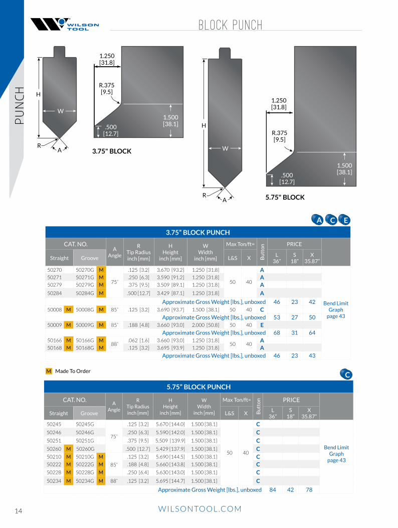
BLOCK PUNCH
5.75” BLOCK PUNCH
CAT. NO.A
Angle
R Tip Radius inch [mm]
H Height
inch [mm]
W Width
inch [mm]
Max Ton/ft=
Bu
tto
n PRICE
Straight Groove L&S XL
36”S
18”X
35.87”
50245 50245G
75˚
.125 [3.2] 5.670 [144.0] 1.500 [38.1]
50 40
C
Bend Limit Graph
page 43
50246 50246G .250 [6.3] 5.590 [142.0] 1.500 [38.1] C
50251 50251G .375 [9.5] 5.509 [139.9] 1.500 [38.1] C
50260 M 50260G .500 [12.7] 5.429 [137.9] 1.500 [38.1] C50210 M 50210G M
85˚
.125 [3.2] 5.690 [144.5] 1.500 [38.1] C50222 M 50222G M .188 [4.8] 5.660 [143.8] 1.500 [38.1] C50228 M 50228G M .250 [6.4] 5.630 [143.0] 1.500 [38.1] C
50234 M 50234G M 88˚ .125 [3.2] 5.695 [144.7] 1.500 [38.1] C
Approximate Gross Weight [lbs.], unboxed 84 42 78
3.75” BLOCK PUNCH
CAT. NO.A
Angle
R Tip Radius inch [mm]
H Height
inch [mm]
W Width
inch [mm]
Max Ton/ft=
Bu
tto
n PRICE
Straight Groove L&S XL
36”S
18”X
35.87”
50270 50270G M
75˚
.125 [3.2] 3.670 [93.2] 1.250 [31.8]
50 40
A
Bend Limit Graph
page 43
50271 50271G M .250 [6.3] 3.590 [91.2] 1.250 [31.8] A50279 50279G M .375 [9.5] 3.509 [89.1] 1.250 [31.8] A
50284 50284G M .500 [12.7] 3.429 [87.1] 1.250 [31.8] A
Approximate Gross Weight [lbs.], unboxed 46 23 4250008 M 50008G M 85˚ .125 [3.2] 3.690 [93.7] 1.500 [38.1] 50 40 C
Approximate Gross Weight [lbs.], unboxed 53 27 5050009 M 50009G M 85˚ .188 [4.8] 3.660 [93.0] 2.000 [50.8] 50 40 E
Approximate Gross Weight [lbs.], unboxed 68 31 6450166 M 50166G M
88˚.062 [1.6] 3.660 [93.0] 1.250 [31.8]
50 40A
50168 M 50168G M .125 [3.2] 3.695 [93.9] 1.250 [31.8] AApproximate Gross Weight [lbs.], unboxed 46 23 43
H
W
RA
.500[12.7]
1.500[38.1]
R.375[9.5]
1.250[31.8]
H
W
RA
.500[12.7]
1.500[38.1]
R.375[9.5]
1.250[31.8]
3.75" BLOCK
5.75" BLOCK
A B C D E GF HA B C D E GF HA B C D E GF H
A B C D E GF H
PUNCH
Made To OrderM

15WILSONTOOL.COM WILSONTOOL.COM
8 .75 ” PUNCH
8.75” SASH GOOSENECK PUNCH
CAT. NO.A
Angle
R Tip Radius inch [mm]
H Height
inch [mm]
Max Ton/ft=
Bu
tto
n PRICE
Straight Groove S & XS
18X
35.8750373 50373G M
75˚
.031 [0.8] 8.730 [221.7] 25 H
Bend Limit
Graph page 45
50374 50374G M .062 [1.6] 8.710 [221.2]35
H50375 M 50375G M .125 [0.8] 8.670 [220.2] H50376 M 50376G M
88˚.031 [0.8] 8.736 [220.2]
35
H50377 M 50377G M .062 [1.6] 8.723 [221.6] H50378 M 50378G M
90˚.031 [0.8] 8.737 [221.9] H
50379 M 50379G M .062 [1.6] 8.724 [221.6] C
Approximate Gross Weight [lbs.], unboxed 56 102
8.75" ACUTE PUNCH
CAT. NO. A
Angle
R Tip Radius inch [mm]
H Height
inch [mm]
Max Ton/ft=
Bu
tto
n PRICE
Straight Groove S & XS
18"X
35.87"50363 50363G M
30˚
.031 [0.8] 8.661 [220.0] 30 C Bend Limit
Graph page 46
50364 50364G M .062 [1.6] 8.571 [217.7] 35 C50365 M 50365G M .125 [0.8] 8.392 [213.2] 35 H
Approximate Gross Weight [lbs.], unboxed 35 71
R.375[9.5]
1.250[31.8]
.500[12.7]
1.339[ 34.01 ]
2.625[60.7]
H
A
R
.738[18.7]
.438
1.839[46.71].750
[19.1]
1.250[31.8]
R.375[9.5]
H
1.500[38.1]
R
.750[19.1]
A
A B C D E GF H
A B C D E GF H
All tonnages are based on direct load and do not apply for thrusting applications.
PUNCH
8.75" SASH GOOSENECK 8.75" ACUTE
Made To OrderM
A B C D E GF H
A B C D E GF H
All 8.75” Punches:
Short = solid safety tang
X = solid safety tang on 8” and 12” sections.
16 WILSONTOOL.COM WILSONTOOL.COM
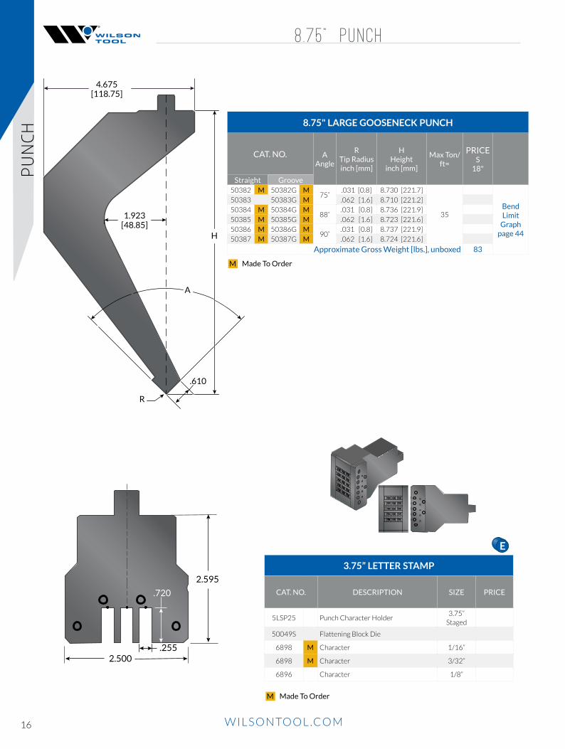
8.75" LARGE GOOSENECK PUNCH
CAT. NO. A Angle
R Tip Radius inch [mm]
H Height
inch [mm]
Max Ton/ft=
PRICE S
18"
Straight Groove50382 M 50382G M
75˚.031 [0.8] 8.730 [221.7]
35Bend Limit
Graph page 44
50383 50383G M .062 [1.6] 8.710 [221.2]
50384 M 50384G M88˚
.031 [0.8] 8.736 [221.9]
50385 M 50385G M .062 [1.6] 8.723 [221.6]
50386 M 50386G M90˚
.031 [0.8] 8.737 [221.9]
50387 M 50387G M .062 [1.6] 8.724 [221.6]
Approximate Gross Weight [lbs.], unboxed 83
1.923[48.85]
R
A
.610
H
4.675[118.75]
8 .75 ” PUNCH
3.75” LETTER STAMP
CAT. NO. DESCRIPTION SIZE PRICE
5LSP25 Punch Character Holder3.75”
Staged
50049S Flattening Block Die
6898 M Character 1/16”
6898 M Character 3/32”
6896 Character 1/8”
2.500
2.595
.720
.255
PUNCH
A B C D E GF H
Made To OrderM
Made To OrderM
17WILSONTOOL.COM WILSONTOOL.COM
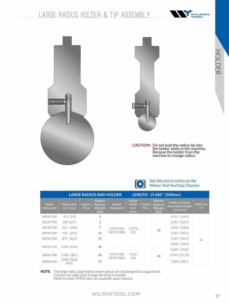
LARGE RAD IUS HOLDER & T IP ASSEMBLY
LARGE RADIUS AND HOLDER LENGTH: 19.685" [500mm]
Radius Material #
Radius Sizeinch [mm]
Radius Price
Radius Approx. Weight
[lbs]
Holder Material #
Holder Width
inch [mm]
Holder Price
Holder Approx. Weight
[lbs]
Holder & Radius Assembled Height
inch [mm]
MAX Ton / Ft
6R095-500 .375 [9.5] 3
54T35-50054T35-500G
1.3778 [35]
25
4.511 [114.5]
21
6R127-500 .500 [12.7] 5 4.781 [121.4]
6R158-500 .625 [15.8] 7 5.050 [128.3]
6R190-500 .750 [19.0] 10 5.319 [135.1]
6R222-500 .875 [22.2] 14 5.589 [141.9]
6R254-500 1.000 [25.4] 185.858 [148.9]
54T55-50054T55-500G
2.165 [55]
38
5.669 [144.0]
6R381-500 1.500 [38.1] 40 6.747 [171.37]
6R508-5002.000 [50.8]
MTO72 7.824 [198.7]
NOTE: The large radius assemblies shown above are not designed to stage bend. Contact our sales desk if stage bending is needed. Make to order (MTO) sizes are available upon request.
CAUTION: Do not load the radius tip into the holder while in the machine. Remove the holder from the machine to change radius.
See this tool in action on the Wilson Tool YouTube Channel
HOLD
ER

18 WILSONTOOL.COM WILSONTOOL.COM
V-ser ies black
MODEL 1 MODEL 2 MODEL 3
[60.0]2.362
[28.5]1.122
[65.0]2.558
[41.5]1.634
[90.0]3.54
[90.0]3.54
[28.5]1.122
[55.0]2.165
[100.0]3.937
[12.7].500
[41.5]1.634
[12.7].500
[100.0]3.937
[12.7].500
[90.0]3.54
[70.0]2.756
[100.0]3.937
[55.0]2.165
[28.5]1.122
[13.0].512
[100.0]3.937
[13.0].512
[13.0].512
[60.0]2.362
[41.5]1.634
[70.0]2.756 [90.0]
3.54
[60.0]2.362
41060 42065 43090
51055 51100 53070
61055 61100 62060 62100 63070
52060 52100
MODEL 1 AMERICAN PRECISION V-SERIES BLACK
Hei
ght 9.84” [250mm] 19.68” [500mm] SOLID 21.65” [550mm] SECTIONAL SPRINGS
AssemblyCAT. NO.
WT.[lbs.]
PRICE AssemblyCAT. NO.
WT.[lbs.]
PRICE 250 InsertCAT. NO.
AssemblyCAT. NO.
WT.[lbs.]
PRICE InsertsCAT. NO.
CAT. NO.
500 mm QTY
550 mm QTY
55 51055-250 6 51055-500 11(4) 980872A
51055-550 13 980873A and
980874A
98068240 44
100 51100-250 10 51100-500 20 51100-550 22 981031
MODEL 2 AMERICAN PRECISION V-SERIES BLACK
Hei
ght 9.84” [250mm] 19.68” [500mm] SOLID 21.65” [550mm] SECTIONAL SPRINGS
AssemblyCAT. NO.
WT.[lbs.]
PRICE AssemblyCAT. NO.
WT.[lbs.]
PRICE 250 InsertCAT. NO.
AssemblyCAT. NO.
WT.[lbs.]
PRICE InsertsCAT. NO.
CAT. NO.
500 mm QTY
550 mm QTY
60 52060-250 9 52060-500 15(4) 980948
52060-550 17 980949 and
980950
98068240 44
100 52100-250 14 52100-500 25 52100-550 29 981032
MODEL 3 AMERICAN PRECISION V-SERIES BLACK
Hei
ght 9.84” [250mm] 17.91” [455mm] SPRINGS
AssemblyCAT. NO.
WT.[lbs.]
PRICE 250 InsertCAT. NO.
AssemblyCAT. NO.
WT.[lbs.]
PRICE InsertsCAT. NO.
CAT. NO.
WT.[lbs.]
500 mm QTY
550 mm QTY
70 53070-250 27 980959 53070-455 47980960
and 980977
980881 .25 8 18
INSTALLATION TOOLS
DESCRIPTION CAT. NO. PRICE
Spring Installation Tool Kit 981002
Spring Extension Wire (short) 981003
Spring Extension Wire (long) 981004
ZIP-MAR URETHANE SHOULDER STRIPS[54’ Roll, .020” Thick]
DESCRIPTION CAT. NO. PRICE
Model 1, 1/2” wide 980953
Model 2, 3/4” wide 980954
Model 3, 1-5/8” wide 980955
See this tool in action on the Wilson Tool YouTube Channel
V-S
ERIES
BLACK

19WILSONTOOL.COM WILSONTOOL.COM
v-ser ies black
Model 1 & 219.68” [500mm] Solid Total Length 21.65” [550mm] Sectional (Shown) Total Length
3.937[100]
3.937[100]
3.937[100]
1.771[45]
1.574[40]
1.378[35]
1.181[30]
inch[mm]
.984[25]
.984[25]
1.968[50]
Model 3
3.937[100]
3.937[100]
3.937[100]
1.771[45]
inch[mm]
1.968[50]
2.362[60]
9.84” [250mm] Solid Total Length 17.91” [455 mm] Sectional (Shown) Total Length
V OPENING AND SHOULDER RADIUS DIMENSIONS
MODELSHOULDER
RADinch/[mm]
DESIRED ANGLE
THEORETICAL V - METRIC
THEORETICAL V - IMPERIAL
1 .040 [1.0]90º 7.2 0.28334º 6.5 0.256
2 .051 [1.3]90º 13.9 0.54742º 13.3 0.524
3 .236 [6.0]90º 33.0 1.29965º 31.4 1.236
V-SERIES BLACK SPECIFICATIONS
ModelMaterial
Thicknessinch [mm]
Min. Outside Flange
inch [mm]
Ton/FT
Min. Angle
Punch Tip Required
to Achieve Angle
Max OR Radius @
Min. Angleinch [mm]
Max OR Radius @
90°inch [mm]
Tonnage Cap/FT T/M kN/M
1
.018 [.45]
.118 [3.0]
1.8
34º
0.054
.125 [3.17] .175 [4.45] 34 112 1100
.020 [.50] 1.8 0.052
.024 [.60] 2.0 0.047
.030 [.80] 2.5 0.042
.036 [.90] 3.3 0.036
.040 [1.0].153 [3.9]
4.00.031.048 [1.2] 5.8
.063 [1.5] .165 [4.2] 9
2
.074 [1.9] .335 [8.5] 7
42º
0.122
.216 [5.5].354 [9.0] 50 168 1650
.105 [2.9] .347 [8.8] 13 0.112
.118 [3.0].366 [9.3]
15 0.099.126 [3.2] 20 0.091.135 [3.4] 22 55º 0.082 .276 [7.9]
3.157 [4.0]
.886 [22.5]9
65º0.078
.453 [11.5] .797 [20.2] 60 204 2000.187 [4.75] 26 0.094.250 [6.35] 28 0.125
V-SER
IES BLACK
V-SERIES BLACK STANDARD LENGTHS

20 WILSONTOOL.COM
URETHANE D IESDIES
50031u 50032u 50033u 50034u
50035u 50036u 50037u 50018u
50020u 50021u 50022u 50023u
300
16 GA.1 3/4”
1/2”
1 1/4”
900
13 GA.
3/4”
1 3/4”
1 3/4”
900
12 GA.
7/8”
1 7/8”
1 3/4”
900
11 GA.
1”
1 7/8”
1 3/4”
300
14 GA.1 3/4”
5/8”
1 7/8”
900
22 GA.1 3/4”
1 1/4”
1/4”900
18 GA.1 3/4”
3/8”
1 1/4”
900
14 GA.
5/8”
1 3/4”
1 3/4”
900
16 GA.1 3/4”
1 1/4”
1/2”
300
18 GA.1 3/4”
3/8”
1 1/4”
300
22 GA.1 3/4”
1/4”
1 1/4”
850
3”
2”
2 1/4” 10 GA.
URETHANE DIES
CAT. NO. ANGLEV
OpeningH
HeightW
Width
Approx. Gross Weight [lbs]
PRICE
Length 48”
Length 96”
Length 48"
Length 96”
50031u
900
1/4" 1-3/4" 1-1/4" 5 12
50032u 3/8" 1-3/4" 1-1/4" 5 12
50033u 1/2" 1-3/4" 1-1/4" 6 12
50034u 5/8" 1-3/4" 1-3/4" 7 16
50035u 3/4" 1-3/4" 1-3/4" 7 16
50036u 7/8" 1-7/8" 1-3/4" 7 16
50037u 1" 1-7/8" 1-3/4" 7 17
50018u 850 2" 2-1/4" 3" 5 N/A
50020u
300
1/4" 1-3/4" 1-1/4" 5 12
50021u 3/8" 1-3/4" 1-1/4" 5 12
50022u 1/2" 1-3/4" 1-1/4" 7 16
50023u 5/8" 1-7/8" 1-3/4" 7 16

21WILSONTOOL.COM
TRADITIONAL NON-STAGE BENDING STAGE BENDING 3 Different Shut Heights 1 Common Shut Height
WHAT IS STAGE BENDING?In a press brake, stage bending is the process of developing multiple tooling setups that have a common shut height or ‘Stage Bending’. This enables press brake operators to carryout multiple bends with a single setup. Groups of tools are set up progressively along the press brake, then all bends on a single part are performed in succession.
To successfully accomplish stage tooling, each tool in a set must share:
MATCHING ANGLES
5.250STAGE
Angles matchand lands
bottom out
30º 90º
30º 90º
NON-MATCHING ANGLES
30º
30º
90º
90º
Angles do notmatch and
lands bottom out
5.173NOT
STAGE
5.773NOT
STAGE
5.250SERIES
7.250SERIES
10.250SERIES
3.75”Punch
5.75”Punch
8.75”Punch
MATCHING ANGLES
5.250STAGE
Angles matchand lands
bottom out
30º 90º
30º 90º
NON-MATCHING ANGLES
30º
30º
90º
90º
Angles do notmatch and
lands bottom out
5.173NOT
STAGE
5.773NOT
STAGE
5.250SERIES
7.250SERIES
10.250SERIES
3.75”Punch
5.75”Punch
8.75”Punch
A common shut height (total height of each punch and die combined is the same).
Stage bending simplifies complex jobs by eliminating unproductive repetitive tasks - signficantly reducing setup time, part handling and work-in-progress.
STAGE BEN
DIN
G
See this tool in action on the Wilson Tool YouTube Channel
STAGE BEND ING

22 WILSONTOOL.COM
DIES
STAGED ACUTE AND BLOCK D IES
Use Theoretical Sharp dimensions to calculate tonnage and minimum flange.
All tonnages are based on direct load and do not apply for thrusting applications.
1.75" tall dies available upon request.
STAGED BLOCK DIES
CAT. NO. A
Angle
V V OPENING
inch [mm]
H Height
inch [mm]
W Width
inch [mm]
R1 SH. Radius inch [mm]
R2 V Radius
inch [mm]
Max Ton/ft=Approx. Gross
Weight [lbs] PRICE
L&S XL
36”S
18”X
35.87”L
36”S
18”X
35.87”50293
75˚
.250 [6.4] 1.663 [42.2] 1.000 [25.4] .031 [0.8] .016 [0.4]
30 25
21 11 2150237 .375 [9.5] 1.744 [44.3] 1.000 [25.4] .047 [1.2] .016 [0.4]
50238 .500 [12.7] 1.826 [46.4] 1.000 [25.4] .062 [1.6] .016 [0.4]
50294 .625 [15.9] 1.907 [48.4] 1.000 [25.4] .078 [2.0] .016 [0.4]
50239 .750 [19.1] 1.989 [50.5] 1.250 [31.8] .156 [4.0] .031 [0.8]21 14 27
50295 .875 [22.2] 2.070 [52.6] 1.250 [31.8] .156 [4.0] .031 [0.8]
50190
88˚
.250 [6.4] 1.629 [41.4] 1.000 [25.4] .031 [0.8] .016 [0.4]
21 11 2150191 .375 [9.5] 1.694 [43.0] 1.000 [25.4] .047 [1.2] .016 [0.4]
50205 .500 [12.7] 1.759 [44.7] 1.000 [25.4] .062 [1.6] .016 [0.4]
50192 .625 [15.9] 1.824 [46.3] 1.000 [25.4] .078 [2.0] .031 [0.8]
50193 .750 [19.1] 1.888 [48.0] 1.250 [31.8] .156 [4.0] .031 [0.8]26 13 26
50194 .875 [22.2] 1.953 [49.6] 1.250 [31.8] .156 [4.0] .031 [0.8]
50031
90˚
.250 [6.4] 1.625 [41.4] 1.000 [25.4] .031 [0.8] .016 [0.4]
21 20 2050032 .375 [9.5] 1.688 [42.9] 1.000 [25.4] .047 [1.2] .016 [0.4]
50033 .500 [12.7] 1.750 [44.5] 1.000 [25.4] .062 [1.6] .016 [0.4]
50034 .625 [15.9] 1.813 [46.1] 1.000 [25.4] .078 [2.0] .031 [0.8]
50035 .750 [19.1] 1.875 [47.6] 1.250 [31.8] .156 [4.0] .031 [0.8]26 13 26
50036 .875 [22.2] 1.938 [49.2] 1.250 [31.8] .156 [4.0] .031 [0.8]
.500Radius Center
.404Theoretical Sharp
A
TheoreticalSharp
RadiusCenter
A
H
30ºV
.625[15.9]
W
R1
.500[12.7]
W
.500[12.7]
H
V
A
.625[15.9]
R2
R1
STAGE BLOCK
STAGED ACUTE DIES
CAT. NO. V
V-OPENING inch [mm]
H Height
inch [mm]
W Width
inch [mm]
R1 SH. Radius inch [mm]
Radius Center [inch]
Theoretical Sharp[inch]
Max Ton/ft=
Approx. Gross Weight [lbs]
PRICE
L, S & XL
36”S
18”X
35.87”L
36”S
18”X
35.87”
50020 .250 [6.4] 1.832 [46.5] 1.000 [25.4] .047 [1.2] .250 .178 16 17 9 17
50021 .375 [9.5] 2.066 [52.5] 1.000 [25.4] .047 [1.2] .375 .303 20 20 10 20
50022 .500 [12.7] 2.254 [57.3] 1.000 [25.4] .062 [1.6] .500 .404 25 23 12 23
50023 .625 [15.9] 2.487 [63.2] 1.375 [34.9] .062 [1.6] .625 .529 25 31 16 31
51024 .750" [19.1] 2.631 [66.8] 1.500 [38.1] .094 [2.4] .750 .606 25 36 18 36
51025 .875 [22.2] 2.864 [72.7] 1.750 [44.5] .094 [2.4] .875 .731 25 44 22 44
51026 1.000 [25.4] 3.097 [90.5] 2.000 [50.8] .094 [2.4] 1.000 .856 25 42 26 51

23WILSONTOOL.COM
STAGED ARROW AND LARGE V D IES
All tonnages are based on direct load and do not apply for thrusting applications.
1.75", 2.25", 2.75" tall dies available upon request.
STAGED ARROW DIES
CAT. NO.A
Angle
V V OPENING
inch [mm]
H Height
inch [mm]
R1 SH. Radius inch [mm]
R2 V Radius
inch [mm]
Max Ton/ft=Approx. Gross
Weight [lbs] PRICE
L,S & XL
36”S
18”X
35.87”L
36”S
18”X
35.87”50290
75˚
.250" [6.4] 1.663 [42.2] .031 [0.8]
.016 [0.4]
21
14 7 14
50291 .313 [8.0] 1.704 [43.3] .031 [0.8] 14
50292 .375 [9.5] 1.744 [44.3] .047 [1.2] 12
50198
88˚
.250 [6.4] 1.629 [41.4] .031 [0.8] 27
50199 .313 [8.0] 1.662 [42.2] .031 [0.8] 21
50200 .375 [9.5] 1.694 [43.0] .047 [1.2] 21
50004
90˚
.250 [6.4] 1.625 [41.3] .031 [0.8] 26
50005 .313 [8.0] 1.656 [42.1] .031 [0.8] 22
50006 .375 [9.5] 1.688 [42.9] .047 [1.2] 21
STAGED LARGE V DIES
CAT. NO.A
Angle
V V OPENING
inch [mm]
H Height
inch [mm]
W Width
inch [mm]
R1 SH. Radius inch [mm]
R2 V Radius
inch [mm]
Max Ton/ft= Approx. Gross
Weight [lbs] PRICE
L,S & XL
36”S
18”X
35.87”L
36”S
18”X
35.87”50240
75˚
1.000 [25.4] 2.152 [54.7] 1.500 [38.1] .156 [4.0] .031 [0.8] 3033 17 33
50296 1.125 [28.6] 2.233 [56.7] 1.500"[38.1] .156 [4.0] .063 [1.6] 35
50297 1.250 [31.8] 2.315 [58.8] 2.000 [50.8] .188 [4.8] .094 [2.4] 40 45 23 45
50298 1.500 [38.1] 2.477 [62.9] 2.500 [63.5] .188 [4.8] .094 [2.4] 40 59 30 59
50299 2.000 [50.8] 2.803 [71.2] 3.000 [76.2] .219 [5.6] .125 [3.2] 50 76 38 75
50300 2.500 [63.5] 3.129 [79.5] 3.500 [88.9] .250 [6.4] .188 [4.8] 50 94 47 94
50371 3.000 [76.2] 3.455 [87.8] 4.000 [101.6] .281 [7.1] .313 [8.0] 50 N/A 57 114 N/A
50371R 3.000 [76.2] 3.455 [87.8] 4.000 [101.6] .281 [7.1] .313 [8.0] 50 N/A 56 112 N/A
50372 4.000 [101.6] 4.107 [104.3] 5.000 [127.0] .375 [9.5] .313 [8.0] 50 N/A 80 59 N/A
50372R 4.000 [101.6] 4.107 [104.3] 5.000 [127.0] .375 [9.5] .313 [8.0] 50 N/A 59 155 N/A
50016
85˚
1.250 [31.8] 2.182 [55.4] 2.000 [50.8] .188 [4.8] .094 [2.4] 40 44 22 43
50017 1.500 [38.1] 2.319 [58.9] 2.500 [63.5] .188 [4.8] .094 [2.4] 40 56 28 56
50018 2.000 [50.8] 2.591 [65.8] 3.000 [76.2] .219 [5.6] .125 [3.2] 50 71 36 71
50019 2.500 [63.5] 2.864 [72.7] 3.500 [88.9] .250 [6.4] .188 [4.8] 50 88 44 88
5020388˚
1.000 [25.4] 2.018 [51.3] 1.500 [38.1] .156 [4.0] .031 [0.8] 30 32 16 32
50204 1.125 [28.6] 2.083 [52.9] 1.500 [38.1] .156 [4.0] .063 [1.6] 35 32 16 32
5003790˚
1.000 [25.4] 2.000 [50.8] 1.500 [38.1] .156 [4.0] .031 [0.8] 30 31 16 31
50015 1.125 [28.6] 2.063 [52.4] 1.500 [38.1] .156 [4.0] .063 [1.6] 35 32 16 32
.500[12.7]
.625[15.9]
H
V
A
R2
R1
1.000[25.4]
.500[12.7]
.625[15.9]
H
V
A
.500[12.7]
R2
R1
ARROW LARGE V
DIES
.500[12.7]
.625[15.9]
H
V
A
R2
R1
1.000[25.4]
.500[12.7]
.625[15.9]
H
V
A
.500[12.7]
R2
R1
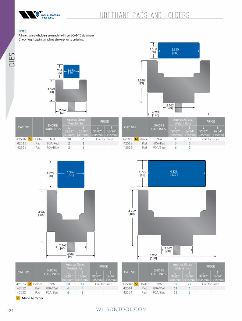
24 WILSONTOOL.COM
URETHANE PADS AND HOLDERS
4.252[108]
5.906[150]
4.331[ 110 ]
1.772[45]
2.362[60]
CAT. NO.SHORE
HARDNESS
Approx. Gross Weight [lbs]
PRICE
L 32.87”
[835mm]
S16.34”
[415mm]
L 32.87"
[835mm]
S16.34"
[415mm]
42501c M Holder N/A 10 6 Call for Price
42511 Pad 80A/Red 2 1
42521 Pad 90A/Blue 2 1
2.362[60]
1.693[43]
1.181[ 30 ]
.984[25]
NOTE:All urethane die holders are machined from 6061-T6 aluminum.Check height against machine stroke prior to ordering.
4.724[120]
3.268[83]
3.150[ 80 ]
1.183[50]
2.362[60]
2.362[60]
3.583[91]
3.937[100]
1.969[ 50 ]
1.969[50]
CAT. NO.SHORE
HARDNESS
Approx. Gross Weight [lbs]
PRICE
L 32.87”
[835mm]
S16.34”
[415mm]
L 32.87"
[835mm]
S16.34"
[415mm]
42503c M Holder N/A 35 19 Call for Price
42513 Pad 80A/Red 6 3
42523 Pad 90A/Blue 6 3
CAT. NO.SHORE
HARDNESS
Approx. Gross Weight [lbs]
PRICE
L 32.87”
[835mm]
S16.34”
[415mm]
L 32.87"
[835mm]
S16.34"
[415mm]
42502c M Holder N/A 33 17 Call for Price
42512 Pad 80A/Red 6 3
42522 Pad 90A/Blue 6 3
CAT. NO.SHORE
HARDNESS
Approx. Gross Weight [lbs]
PRICE
L 32.87”
[835mm]
S16.34”
[415mm]
L 32.87"
[835mm]
S16.34"
[415mm]
42504c M Holder N/A 52 27 Call for Price
42514 Pad 80A/Red 11 6
42524 Pad 90A/Blue 11 6
DIES
Made To OrderM

25WILSONTOOL.COM
OFFSET PUNCH AND D IE
** T= Offset dimension top of sheet to top of form
Offset tools can be used as a punch or a die.
Sold as a set - individual tools available.
Dimensions are shut height requirements less material thickness.
Offset height may vary as much as -.020”[0.5mm] after bending as all angles will be obtuse.
Special offset sizes available at additional cost.
All tonnages are based on direct load and do not apply for thrusting applications.
3.75" OFFSET PUNCH AND DIE SET
CAT. NO. **T Offset Dim.
inch [mm]
H Height
inch [mm]
W Width
inch [mm]
R3 SH.
Radius inch [mm]
D Centerline
Dim. inch [mm]
Max Ton/ft=
Approx. Gross Weight [lbs]
Bu
tto
n PRICE
Straight Groove L&S XL
36”S
18”X
35.87”L
36”S
18”X
35.87”
50087 50087G M .125 [3.2] 2.663 [66.6] 1.250 [31.8] .062 [1.6] .625 [15.9]
30 25
71 35 71
A
50088 50088G M .188 [4.8] 2.685 [68.2] 1.250 [31.8] .062 [1.6] .625 [15.9] A
50089 50089G M .250 [6.4] 2.707 [68.8] 1.250 [31.8] .094 [2.4] .625 [15.9] A
50090 50090G M .375 [9.5] 2.745 [69.7] 1.250 [31.8] .125 [3.2] .625 [15.9] A
50091 50091G M .500 [12.7] 2.789 [70.8] 1.500 [38.1] .125 [3.2] .750 [19.1] 86 43 86 C
50092 50092G M .625 [15.9] 2.833 [72.0] 1.750 [44.5] .125 [3.2] .875 [22.2] 100 50 100 C
50093 50093G M .750 [19.1] 2.877 [73.1] 2.000 [50.8] .125 [3.2] .875 [22.2] 114 58 114 C
T X 1.414” = Effective V
A B C D E GF HA B C D E GF H
H
.500[12.7]
W
.500[12.7]
.500[12.7]
W
.500[12.7]
H
W
5.250[133.3]
D
.500[12.7] .500
[12.7]
H
90º
R3
T
R3
.016[0.4]
.016[0.4]
.016[0.4]
.016[0.4]
OFFSET
Made To OrderM

26 WILSONTOOL.COM WILSONTOOL.COM
All tonnages are based on direct load and do not apply for thrusting applications.
Note: Maximum material is 16 ga. cold rolled steel.
5.75" TWO STAGE HEMMING PUNCH AND DIE SET
CAT. NO.Max Ton/
ft=Weight
/inch
Bu
tto
n PRICE
Straight Groove L, S, XL
36”S
18”X
35.87”L
36”S
18”X
35.87”
51919 51919G M Punch 25 54 29 54 B
53594 NA M Die 21 83 42 83 -
1.375[34.93]
R.031[0.79]
30º
5.661[143.79]
.031[0.79]
R
.394[10.00]
V
.625[15.88]
3.840[97.52]
.500[12.7]
2.500[63.5]
HEMMING AND FLATTEN ING
A B C D E GF H
HEM
MIN
G
Made To OrderM
H
.500[12.7]
W
.500[12.7]
.500[12.7]
W
.500[12.7]
H
W
5.250[133.3]
D
.500[12.7] .500
[12.7]
H
90º
R3
T
R3
.016[0.4]
.016[0.4]
.016[0.4]
.016[0.4]
THRUST ABSORBING FLATTENING DIE
CAT. NO.MAX. TONFT/METER
LT & ST
PRICE
L 32.87”
[835mm]
S 16.34”
[415mm]
42311c 30 / 100 Call for Price
3.780[96]
4.110[104.4]
3.110[79]
2.362[60]
A B C D E GF H
3.75" FLATTENING PUNCH AND DIE SET
CAT. NO. H Height
inch [mm]
W Width
inch [mm]
Max Ton/ft=
Approx. Gross Weight [lbs]
Bu
tto
n PRICE
Straight Groove L&S XL
36”S
18”X
35.87”L
36”S
18”X
35.87”
50048 50048G M 2.625 [66.7] 1.500 [38.1] 40 35
76 43 87 C
50049 50049G M 2.625 [66.7] 2.500 [63.4] 139 70 138 F
5.75” FLATTENING PUNCH AND DIE SET
50265 50265G M 3.625 [92.1] 1.500 [38.1] 40 35 116 58 120 C
H
.500[12.7]
W
.500[12.7]
.500[12.7]
W
.500[12.7]
H
W
5.250[133.3]
D
.500[12.7] .500
[12.7]
H
90º
R3
T
R3
.016[0.4]
.016[0.4]
.016[0.4]
.016[0.4]

27WILSONTOOL.COM WILSONTOOL.COM
HEMMING AND REPLACEMENT V-BLOCKS
CAT. NO. 43522 CAT. NO. 43524CAT. NO. 43523 CAT. NO. 43528
TWO STAGE HEMMING DIE
CAT. NO.
V1 INCHES
[mm]
HHEIGHTINCHES
[mm]
MAX. TONFT/METER
(LT & ST)
Approx. Gross Weight [lbs]
MAX MATERIAL
PRICE
LT32.87”
[835mm]
ST16.34”
[415mm]
LT32.87”
[835mm]
ST16.34”
[415mm]
42601c.236 [6.0]
4.587 [116.5]
20 / 67 86 43 20 GA. CRS Call for Price
42602c.315 [8.0]
4.587 [116.5]
20 / 67 86 43 16 GA. CRS Call for Price
42603c.394
[10.0]4.902
[124.5]20 / 67 89 45 14 GA. CRS Call for Price
42608c.394
[10.0]5.402
[137.2]20 / 67 103 52 14 GA. CRS Call for Price
HEMMING REPLACEMENT V-BLOCKS
CAT. NOMAX. TON
FT / METER(LT & ST)
Approx. Gross Weight [lbs]
MAX MATERIAL
V1 INCHES
[mm]
PRICE
LT32.87”
[835mm]
ST16.34”
[415mm]
LT32.87”
[835mm]
ST16.34”
[415mm]
43522 20 / 67 12 6 20 GA. CRS .236 [6.0]
43523 20 / 67 12 6 16 GA. CRS .315 [6.0]
43524 20 / 67 15 8 14 GA. CRS .394 [10.0]
43528 25 / 83 29 15 14 GA. CRS .394 [10.0]
.551[14]
.906[23]
.236[6]
.630[16]
.039[1]
.630[16]
.551[14]
.906[23]
.315[8]
.039[1]
.394[10]
.630[16]
.866[22]
.039[1]
1.220[31]
.394[10]
1.181[30]
.118[3]
1.720[43.7]
H
2.362[60]
HEM
MIN
G

28 WILSONTOOL.COM WILSONTOOL.COM
Note: All holders include clamping set screws every 2" [50.8mm]
All tonnages are based on direct load and do not apply for thrusting applications.
Note: All holders include clamping set screws every 2" [50.8mm]
H
.500[12.7].500
[12.7]
1.875[47.63]
.875[22.23]
1.000[25.4]
GROOVE CLAMPING TO GROOVE PUNCH TANG
CAT. NO. H
Height inch [mm]
Max Ton/ft=
Approx. Gross Weight [lbs]
Bu
tto
n PRICE
L, S, X L 36”
S 18”
X 35.87”
L 36"
S 18"
X 35.87"
50158G M 2.000 [50.8]30
35 18 37 E
50096G M 4.000 [101.6] 75 37 78 E
PUNCH HOLDER
Note: All holders include clamping set screws every 2" [50.8mm]
All tonnages are based on direct load and do not apply for thrusting applications.
EUROPEAN Z1 TO AMERICAN
CAT. NO.
Approx. Gross Weight [lbs]
Max Ton/ft= PRICE
L36”
S18”
X35.87”
L, S, X L
36”S
18”X
35.87”
43851 33 16 32 30
2.000[50.8]
1.75[44.45]
1.101[27.97]
.276[7]
AMERICAN TO AMERICAN STRAIGHT TANG
CAT. NO. H
Height inch [mm]
Max Ton/ft=
Approx. Gross Weight [lbs]
Bu
tto
n PRICE
L, S, X L 36”
S 18”
X 35.87”
L 36"
S 18"
X 35.87"
50157 2.000 [50.8]
30
36 18 35 E
50081 3.000 [76.2] 54 27 53 D
50082 4.000 [101.6] 73 37 73 E
A B C D E GF H
A B C D E GF H
HOLD
ER
2.000[50.8]
1.75[44.45]
1.101[27.97]
.276[7]
Made To OrderM

29WILSONTOOL.COM WILSONTOOL.COM
1.750[44.45]
2.00[50.8]
1.101[27.97]
.787[20]
PUNCH HOLDER
EUROPEAN Z2 TO AMERICAN
CAT. NO. H
Height inch [mm]
Max Ton/ft=
Approx. Gross Weight [lbs]
PRICE
L, S, X L 36”
S 18”
X 35.87”
L 36"
S 18"
X 35.87"
43852 2.000 [50.8] 30 35 18 35
Z2 SERIES WITH DUAL AMERICAN AND EUROPEAN CLAMPING
CAT. NO. Approx. Gross
Weight [lbs]Max Ton/ft= PRICE
43853 15 30
CL
4.724
.787Z-2
5.905[150]
HOLD
ER
Note: All holders include clamping set screws every 2" [50.8mm]

30 WILSONTOOL.COM WILSONTOOL.COM
AMERICAN TO AMERICAN
CAT. NO.
H Height
inch [mm]
Max Ton/ft=
Approx. Gross Weight [lbs]
PRICE
L, S, X L
36”S
18”X
35.87”L
36"S
18"X
35.87"
50084 2.000 [50.8]
40
30 15 30
50085 3.000 [76.2] 45 23 45
50086 4.000 [101.6] 60 30 60
Custom M Specify - - - Call for Pricing
Note: All holders include clamping set screws every 2" [50.8mm]
All tonnages are based on direct load and do not apply for thrusting applications.
EUROPEAN TO AMERICAN
CAT. NO.
Approx. Gross Weight [lbs]
Max Ton/ft= PRICE
L36”
S18”
L & S L
36”S
18”
43590 44 49 40
.500[12.7]
.625[15.9]
H
1.500[38.1]
2.362[60]
2.00[50.80]
D IE HOLDERHOLD
ER
Made To OrderM

31WILSONTOOL.COM WILSONTOOL.COM
BEND ING TH ICK MATER IAL
Wilson Tool also offers several solutions for manufacturers who use thick, heavy materials in their manufacturing process.
ADJUSTABLE V DIE see page 53The Exacta Adjustable V dies are a great solution when bending thick materials and you need the flexibility to adjust the width of the V opening. Instead of buying several dies with different V openings, Exacta Adjustable V dies enable you to adjust the width, rather than changing out the die. Adjustable V openings range from 1 to 24 inches and can be adjusted in 1 inch increments. Adjustable V dies are induction hardened and are capable of withstanding tonnage of up to 200 tons per foot, allowing you to easily bend thick material. Hard chrome rollers help reduce required tonnage by as much as 20%.
REPLACEABLE SHOULDER DIE see page 53When you work with heavy or abrasive materials such as stainless, hardened steel or parts that are not completely de-burred, you can wear out the shoulders of a die long before the entire die is worn out. With Wilson Tool’s Replaceable Shoulder Dies, you eliminate the need to replace the entire die every time a shoulder wears out. Just simply replace the shoulder in the existing die body. This will save you money on every purchase, and because the shoulder inserts are not fixed in place like on an ordinary die, you may see reduced marking as well
CONVENTIONAL PRESS BRAKE TOOLINGWilson Tool offers a complete selection of conventional press brake tooling. Standard or special forming tools can be manufactured in one-piece lengths of up to 20 feet or can be sectionalized to any length required.
If additional surface hardness is needed for working with abrasive or hard material, we offer induction-hardening treatments on punch tips and die openings.
THICK MATERIAL BENDING CONSIDERATIONS:
• Check your Tonnage and Upsize for Strength
• Consider Heat Treat Options
• Increase Punch Radius
• Increase Die Shoulder Radius
THICK
MATER
IAL

32 WILSONTOOL.COM
BEND L
IMIT G
RAPHS
3 .75 ” ACUTE PUNCH - 30º
1.750
2.500
8
7
2
3
4
5
6
1
0
72 3 4 5 610
LEN
GT
H
[L]
WIDTH [W]
W
L
30º ANGLENOTES
CAT. NO.
50045 50045G0.780”
Tip Width50046 50046G
50047 50047G
Punch detail on page 8

33WILSONTOOL.COM
BEND LIM
IT GRAPHS
5 .75 ” ACUTE PUNCH - 30º
1.750
2.500
8
7
2
3
4
5
6
1
0
72 3 4 5 610
LEN
GT
H
[L]
WIDTH [W]
W
L
30º ANGLENOTES
CAT. NO.
50209 50209G0.740”
Tip Width50221 50221G
50227 50227G
Punch detail on page 8

34 WILSONTOOL.COM
BEND L
IMIT G
RAPHS
3 .75 ” LARGE GOOSENECK PUNCH - 75º
1.750
2.500
8
7
2
3
4
5
6
1
0
72 3 4 5 610
LEN
GT
H
[L]
WIDTH [W]
W
L
75º ANGLENOTES
CAT. NO.
50236 50236G
0.438” Tip Width
50277 50277G
50278 50278G
50289 50289G
Punch detail on page 10
35WILSONTOOL.COM
BEND LIM
IT GRAPHS
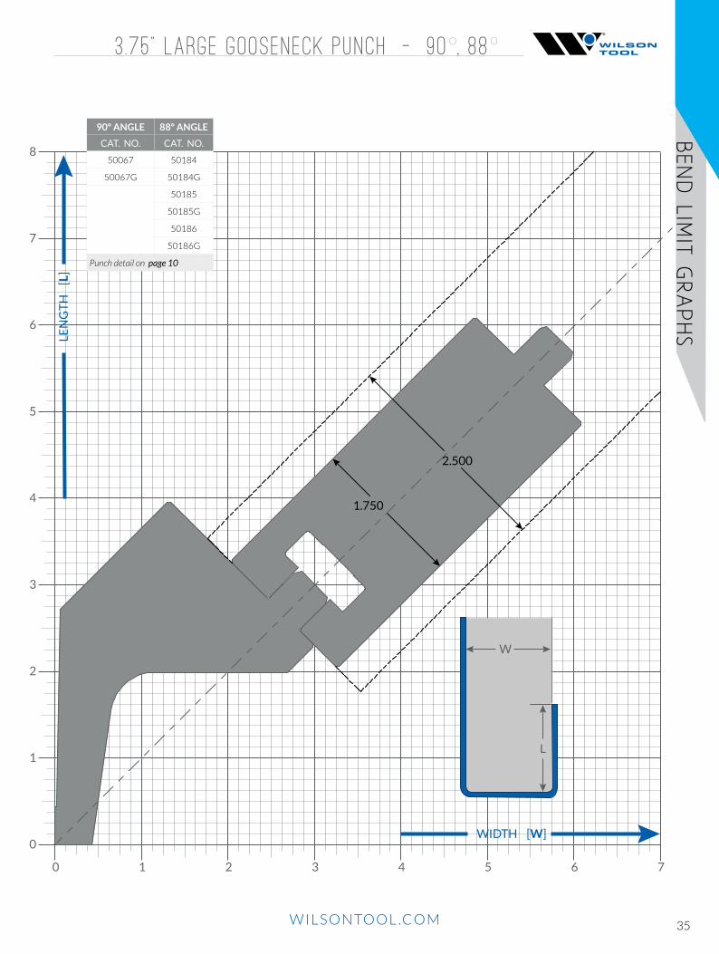
3 .75 ” LARGE GOOSENECK PUNCH - 90º, 88º
8
7
2
3
4
5
6
1
0
72 3 4 5 610
LEN
GT
H
[L]
WIDTH [W]
W
L
1.750
2.500
90º ANGLE 88º ANGLE
CAT. NO. CAT. NO.
50067 50184
50067G 50184G
50185
50185G
50186
50186G
Punch detail on page 10

36 WILSONTOOL.COM
BEND L
IMIT G
RAPHS
5 .75 ” LARGE GOOSENECK PUNCH - 75º
1.750
2.500
8
7
2
3
4
5
6
1
0
72 3 4 5 610
LEN
GT
H
[L]
WIDTH [W]
W
L
75º ANGLENOTES
CAT. NO.
50248 50248G
0.438” Tip Width
50249 50249G
50250 50250G
50266 50266G
Punch detail on page 11
37WILSONTOOL.COM
BEND LIM
IT GRAPHS
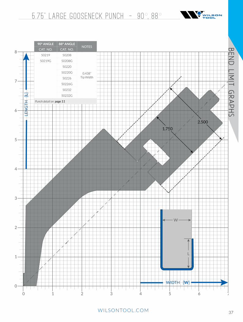
5 .75 ” LARGE GOOSENECK PUNCH - 90º, 88º
1.750
2.500
8
7
2
3
4
5
6
1
0
72 3 4 5 610
LEN
GT
H
[L]
WIDTH [W]
W
L
90º ANGLE 88º ANGLENOTES
CAT. NO. CAT. NO.
50219 50208
0.438” Tip Width
50219G 50208G
50220
50220G
50226
50226G
50232
50232G
Punch detail on page 11

38 WILSONTOOL.COM
BEND L
IMIT G
RAPHS
3 .75 ” SASH PUNCH - 75º
8
7
2
3
4
5
6
1
0
72 3 4 5 610
LEN
GT
H
[L]
WIDTH [W]
W
L
.375 TIP WIDTH
.500 TIP WIDTH
2.500
1.750
75º ANGLE
CAT. NO. NOTES
50281 50281G 0.375” Tip Width50282 50282G
50286 50286G 0.500” Tip Width50287 50287G
Punch detail on page 12

39WILSONTOOL.COM
BEND LIM
IT GRAPHS
3 .75 ” SASH PUNCH - 90º, 88º
1.750
2.500
.250 TIP WIDTH
.375 TIP WIDTH
.500 TIP WIDTH
8
7
2
3
4
5
6
1
0
72 3 4 5 610
LEN
GT
H
[L]
WIDTH [W]
W
L
90º ANGLE 88º ANGLENOTES
CAT. NO. CAT. NO.
50054 50054G 50173 50173G0.250”
Tip Width50055 50055G 50174 50174G
50175 50175G
50058 50058G 50159 50159G0.3750”
Tip Width50059 50059G 50177 50177G
50178 50178G
50063 50063G 50181 50181G 0.500” Tip Width50160 50160G
Punch detail on page 12

40 WILSONTOOL.COM
BEND L
IMIT G
RAPHS
5 .75 ” SASH PUNCH - 75º
1.750
2.500
.375 TIP WIDTH
.500 TIP WIDTH
8
7
2
3
4
5
6
1
0
72 3 4 5 610
LEN
GT
H
[L]
WIDTH [W]
W
L
75º ANGLENOTES
CAT. NO.
50326 50326G 0.3750” Tip Width50327 50327G
50263 50263G0.500”
Tip Width
Punch detail on page 13
41WILSONTOOL.COM
BEND LIM
IT GRAPHS
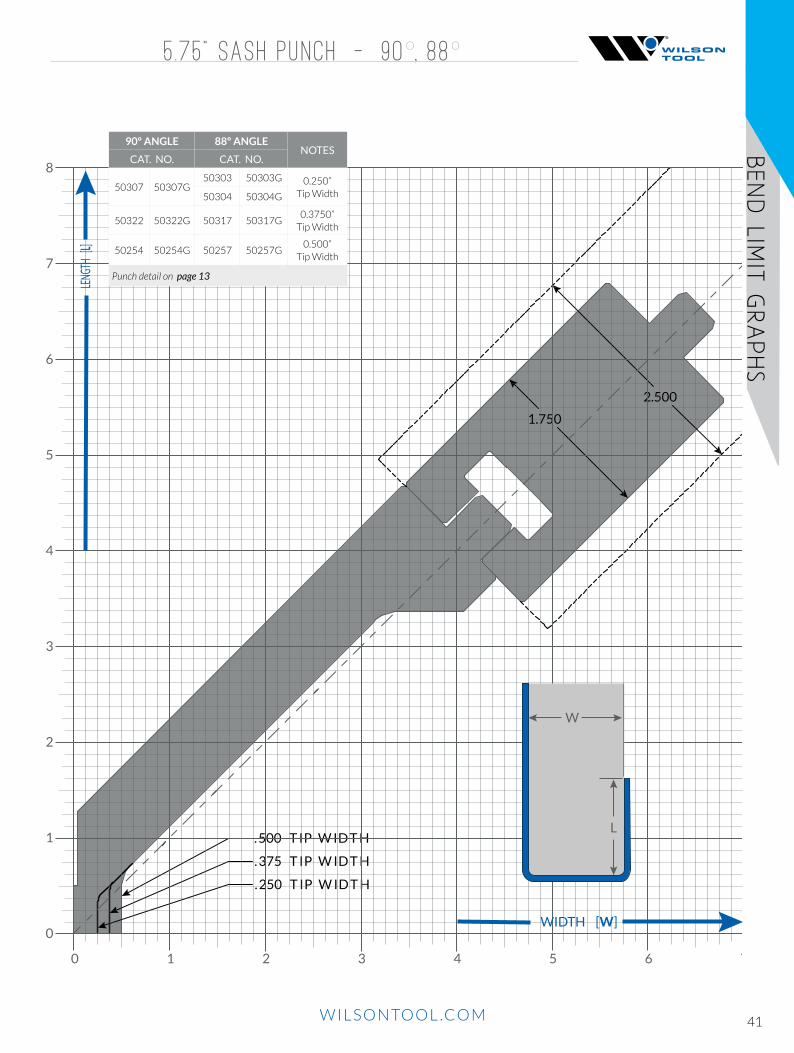
5 .75 ” SASH PUNCH - 90º, 88º
1.750
2.500
. 375 T IP W ID T H
. 250 T IP W ID T H
. 500 T IP W ID T H
8
7
2
3
4
5
6
1
0
72 3 4 5 610
LENG
TH [L]
WIDTH [W]
W
L
90º ANGLE 88º ANGLENOTES
CAT. NO. CAT. NO.
50307 50307G50303 50303G 0.250”
Tip Width50304 50304G
50322 50322G 50317 50317G0.3750”
Tip Width
50254 50254G 50257 50257G0.500”
Tip Width
Punch detail on page 13

42 WILSONTOOL.COM
BEND L
IMIT G
RAPHS
3 .75 ” ARROW PUNCH - 90º, 88º, 75º
1.750
2.500
8
7
2
3
4
5
6
1
0
72 3 4 5 610
LEN
GT
H
[L]
WIDTH [W]
W
L
90º ANGLE 88º ANGLE 75º ANGLE
CAT. NO. CAT. NO. CAT. NO.
50050 50169 50273
50050G 50169G 50273G
50051 50170 50274
50051G 50170G 50274G
50052 50171 50275
50052G 50171G 50275G
50172
50172G
Punch detail on page 9

43WILSONTOOL.COM
BEND LIM
IT GRAPHS
3 .75 ” & 5 .75 ” BLOCK PUNCH - 88º, 85º, 75º
1.750
2.500
1.25" Width
1.50" Width
2.00" Width
8
7
2
3
4
5
6
1
0
72 3 4 5 610
LEN
GT
H
[L]
WIDTH [W]
W
L
3.75” BLOCK PUNCH
88º ANGLE 85º ANGLE 75º ANGLE
CAT. NO. CAT. NO. CAT. NO.
50168 50008 50270
50168G 50008G 50270G
50009 50271
50009G 50271G
50279
50279G
50284
50284G
Punch detail on page 14
5.75” BLOCK PUNCH
88º ANGLE 85º ANGLE 75º ANGLE
CAT. NO. CAT. NO. CAT. NO.
50234 50210 50245
50234G 50210G 50245G
50222 50246
50222G 50246G
50228 50251
50228G 50251G
50260
50260G
Punch detail on page 14
44 WILSONTOOL.COM
BEND L
IMIT G
RAPHS
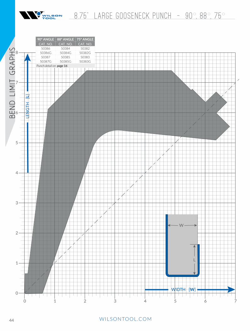
8 .75 ” Large Gooseneck PUNCH - 90º, 88º, 75º
8
7
2
3
4
5
6
1
0
72 3 4 5 610
LEN
GT
H
[L]
WIDTH [W]
W
L
90º ANGLE 88º ANGLE 75º ANGLE
CAT. NO. CAT. NO. CAT. NO.50386 50384 50382
50386G 50384G 50382G
50387 50385 50383
50387G 50385G 50383G
Punch detail on page 16

45WILSONTOOL.COM
BEND LIM
IT GRAPHS
1.750
2.500
8
7
2
3
4
5
6
1
0
72 3 4 5 610
LEN
GT
H
[L]
WIDTH [W]
W
L
8 .75 ” SASH PUNCH - 90º, 88º, 75º
90º ANGLE 88º ANGLE 75º ANGLE
CAT. NO. CAT. NO. CAT. NO.
50378 50376 50373
50378G 50376G 50373G
50379 50377 50374
50379G 50377G 50374G
50375
50375G
Punch detail on page 15

46 WILSONTOOL.COM
BEND L
IMIT G
RAPHS
8 .75 ” acute PUNCH - 30º
1.750
2.500
8
7
2
3
4
5
6
1
0
72 3 4 5 610
LENG
TH [L]
WIDTH [W]
W
L
30º ANGLE
CAT. NO. CAT. NO.
50363 50363G
50364 50364G
50365 50365G
Punch detail on page 15

47WILSONTOOL.COM
BEND LIM
IT GRAPHS
OUR “NEVER SAY NO” ATTITUDEWe regularly help customers with their most challenging applications. Our
innovative solutions simplify complex bends and make the impossible possible.
We are defined by our ‘never say no’ attitude. Bring us your most complex
problem and we will work with you until we’ve found an effective solution.
QUALITY MATERIALS. QUALITY CONTROL.We combine premium materials with specialized manufacturing systems to
produce extraordinary products that outlast the competition.
QUICK QUOTES. SHORT LEAD TIMES.With the fastest lead times in the industry, our tool might ship before the
competition provides a quote.
SPECIALS
C H A L L E N G E U S !
48 WILSONTOOL.COM
SPEC
IALS
SPEC
IALS
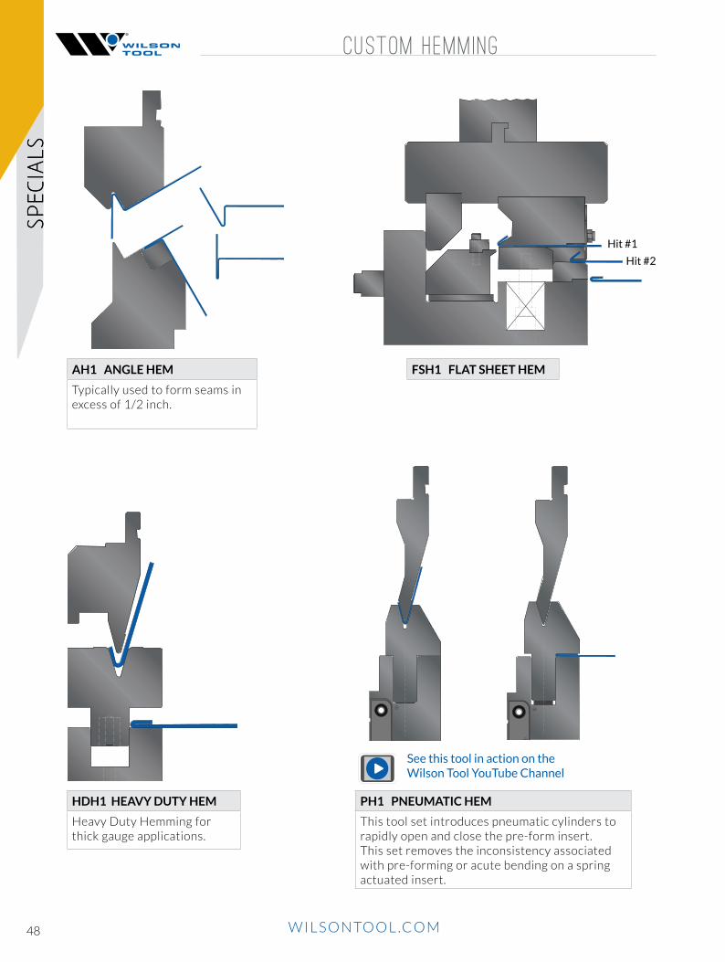
CUSTOM HEMMING
AH1 ANGLE HEM
Typically used to form seams in excess of 1/2 inch.
HDH1 HEAVY DUTY HEM
Heavy Duty Hemming for thick gauge applications.
PH1 PNEUMATIC HEM
This tool set introduces pneumatic cylinders to rapidly open and close the pre-form insert.This set removes the inconsistency associated with pre-forming or acute bending on a spring actuated insert.
FSH1 FLAT SHEET HEM
Hit #1
Hit #2
See this tool in action on the Wilson Tool YouTube Channel
49WILSONTOOL.COM
SPECIA
LSSP
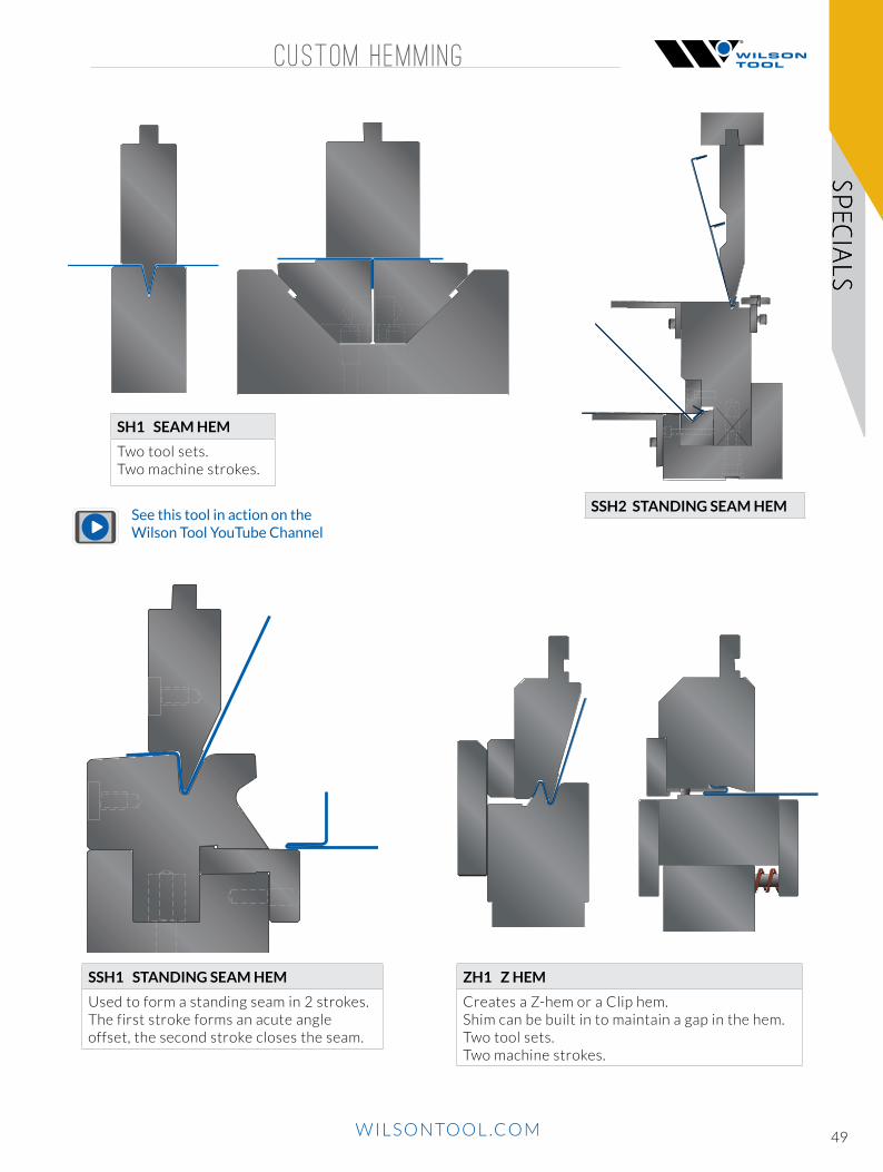
ECIALS CUSTOM HEMMING
SSH1 STANDING SEAM HEM
Used to form a standing seam in 2 strokes.The first stroke forms an acute angle offset, the second stroke closes the seam.
SH1 SEAM HEM
Two tool sets.Two machine strokes.
SSH2 STANDING SEAM HEM
ZH1 Z HEM
Creates a Z-hem or a Clip hem.Shim can be built in to maintain a gap in the hem.Two tool sets.Two machine strokes.
See this tool in action on the Wilson Tool YouTube Channel

50 WILSONTOOL.COM
SPEC
IALS
OFFSET TOOLS
AO1 ANGLED OFFSET
HO1 HORIZONTAL OFFSET
For offsets that are approximately one material thickness.Prevents material whip up.Thrust plates and adjustable back gauging are provided.
LO1 LARGE OFFSET
Used for heavy gauge, large offset bending.
NPO1 NON PARALLEL OFFSET
For offsets that have nonparallel flanges. Inset shows punch hidden for a clear view of the formed sheet.

51WILSONTOOL.COM
SPECIA
LS D IES
REPLACEABLE SHOULDER DIE
Replaceable shoulder dies are ideal for extreme wear conditions created then forming heavy plate and abrasive materials.
Replaceable inserts eliminate the need for replacing the entire die when the die shoulders wear.
Available in multiple V sizes and 75° and 85° configurations.
2" V
4" V
6" V
8" V
ADJUSTABLE DIE
• Can be configured to remain on the press permanently and function as a standard die holder.• 1 - 24” openings available.• Cover bellows available to keep the grooves that are used to adjust the dies free from dirt and dust.• Clamping options for side blocks:
» Manual clamping. » Hydraulic clamping, manual movement. » Hydraulic clamping, automated movement.
See this tool in action on the Wilson Tool YouTube Channel
52 WILSONTOOL.COM
SPEC
IALS
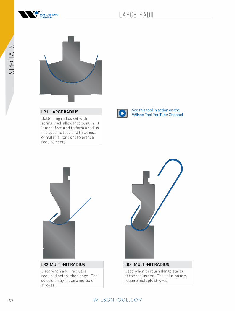
LARGE RAD I I
LR1 LARGE RADIUS
Bottoming radius set with spring-back allowance built in. It is manufactured to form a radius in a specific type and thickness of material for tight tolerance requirements.
LR2 MULTI-HIT RADIUS
Used when a full radius is required before the flange. The solution may require multiple strokes.
LR3 MULTI-HIT RADIUS
Used when th reurn flange starts at the radius end. The solution may require multiple strokes.
See this tool in action on the Wilson Tool YouTube Channel

53WILSONTOOL.COM
SPECIA
LSSTRENGTHEN ING R IB , V-R IB
VR1 V RIB
Produce a V rib in one stroke. Spring back allowance is built in.
SR1 STRENGTHENING RIB
Produce a strengthening rib in one stroke. Spring back allowance is built in. Closed end and open end ribs are available.
See this tool in action on the Wilson Tool YouTube Channel

54 WILSONTOOL.COM
SPEC
IALS
FORMING
A large variety of custom forming sets are available.
Custom built to suit any specific requirement.
Call for specific application requirements.
FM1 FORMING OH1 OPEN HATFM2 FORMING FM3 FORMING
W1 WINDOW
Used when minimum return flange clearance is required.
RB1 ROD BENDING
Provides nesting for the rod during the forming process.
See this tool in action on the Wilson Tool YouTube Channel
55WILSONTOOL.COM
SPECIA
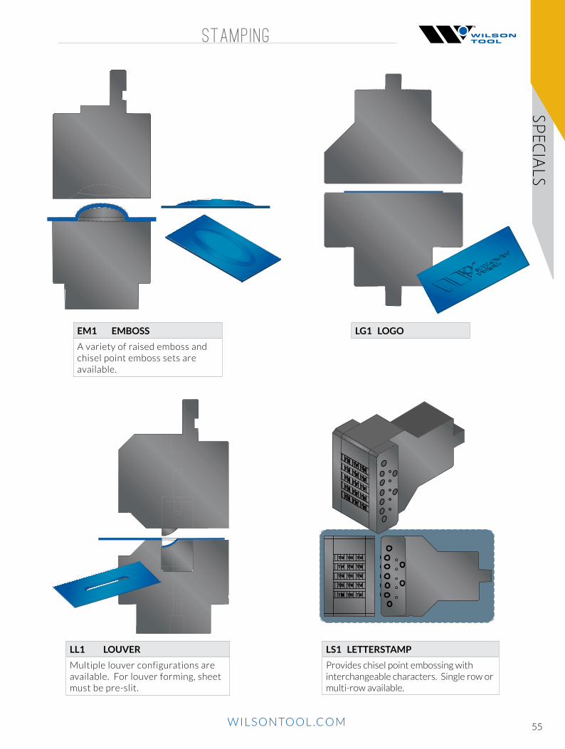
LS STAMPING
LS1 LETTERSTAMP
Provides chisel point embossing with interchangeable characters. Single row or multi-row available.
LG1 LOGOEM1 EMBOSS
A variety of raised emboss and chisel point emboss sets are available.
LL1 LOUVER
Multiple louver configurations are available. For louver forming, sheet must be pre-slit.

56 WILSONTOOL.COM
SPEC
IALS
MECHANICAL
HT1 HAT CHANNEL
Provides straight wall or angled wall hat channel bending in one stroke.Spring back allowance built in.
UC1 U CHANNEL
Recommended for applications where considerable spring back is encountered. Secondary flattening operations may be required.
UC2 U CHANNEL
Recommended for applications where considerable spring back is encountered. Secondary flattening operations may be required.
UC3 U CHANNEL
Recommended for applications where considerable spring back is encountered. Secondary flattening operations may be required.

57WILSONTOOL.COM
SPECIA
LS MECHANICAL
C1 CHANNEL C2 CHANNEL
C3 CHANNEL C4 ROTARY BEND CHANNEL
These applications are for deep channels when the channel bottom needs to remain flat.

58 WILSONTOOL.COM
SPEC
IALS
MECHANICAL
CL2 CURL TOOL SET
Typically used for thick materials and large diameter curls. 1 tool set, 3 machine strokes.
CL3 CURL
Used for hinges and corner beading. 2 tool sets, 2 machine strokes.
CL1 CURL TOOL SET
2 tool sets, 3 machine strokes.
See this tool in action on the Wilson Tool YouTube Channel

59WILSONTOOL.COM
SPECIA
LS MECHANICAL
CL4 CENTER CURL APPLICATION
2 tool sets, 3 machine strokes.
CL5 DOUBLE DECKER TOOL SET
Used for hinges and corner beading. 1 tool set, 2 machine strokes.
See this tool in action on the Wilson Tool YouTube Channel

60 WILSONTOOL.COM
SPEC
IALS
SPEC IAL SHAPE PUNCHES
PR1 PR2 PR3
PR4 PR5 PR6

61WILSONTOOL.COM
SPECIA
LS HOLDERS
EURO Z1 OR Z2 CLAMPING
Cat. No. 43002
AMERICAN DEEP GOOSENECK HOLDER
AMERICAN SELF-SEAT HOLDER
WT - AMERICAN
DIE HOLDER

62 WILSONTOOL.COM
SPEC
IALS
WIP ING AND ROTARY BEND ING
WO1 WIPING FORM
Holds the sheet flat while wiping the flange up or down.
Ideal for large panels and high production.
WD1 WIPE DOWN
Holds the sheet flat while wiping the flange down.
Ideal for large panels and high production.
RTU ROTARY FLANGE FORMING FORM UP
Holds the sheet flat while forming.Overbend allowance is built in to compensate for material springback.
Ideal for large panels and high production.
RTD ROTARY FLANGE FORMING FORM DOWN
Holds the sheet flat while forming.Overbend allowance is built in to compensate for material springback.
Ideal for large panels and high production.
See this tool in action on the Wilson Tool YouTube Channel
See this tool in action on the Wilson Tool YouTube Channel
63WILSONTOOL.COM
SPECIA
LS DEEP BOX BEND ING , SWING EARS
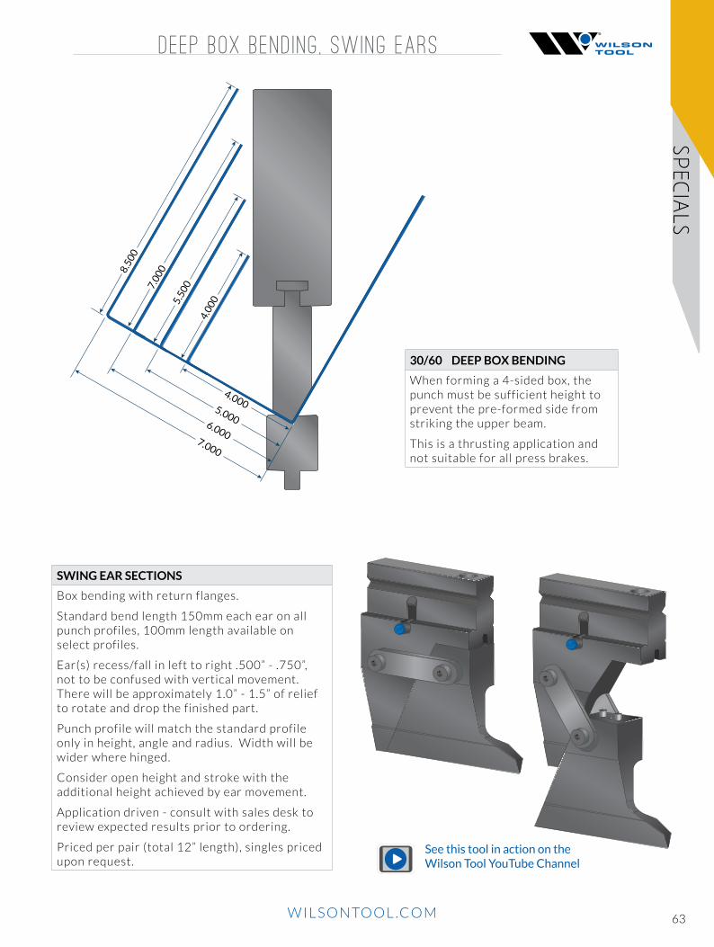
30/60 DEEP BOX BENDING
When forming a 4-sided box, the punch must be sufficient height to prevent the pre-formed side from striking the upper beam.
This is a thrusting application and not suitable for all press brakes.
SWING EAR SECTIONS
Box bending with return flanges.
Standard bend length 150mm each ear on all punch profiles, 100mm length available on select profiles.
Ear(s) recess/fall in left to right .500” - .750”, not to be confused with vertical movement.There will be approximately 1.0” - 1.5” of relief to rotate and drop the finished part.
Punch profile will match the standard profile only in height, angle and radius. Width will be wider where hinged.
Consider open height and stroke with the additional height achieved by ear movement.
Application driven - consult with sales desk to review expected results prior to ordering.
Priced per pair (total 12” length), singles priced upon request.
See this tool in action on the Wilson Tool YouTube Channel

64 WILSONTOOL.COM
SPEC
IALS
TURRET ADAPTER
FRONT VIEW
TA1 TURRET ADAPTER
This tooling set adapts punch press tooling to use in a press brake.
Multiple configurations and options are available.

65WILSONTOOL.COM
SPECIA
LS
C-FRAME TOOLING
Enables operation of single station thin turret tooling in a press brake.
PILOT PIN
DIE
PUNCH
STRIPPING GUIDEASSEMBLY
C-FRAME HOLDER
RAM PLATE
BED RAIL
SPACERS
UNIPUNCH
UNIPUNCH
C-FRAME TOOL ING

66 WILSONTOOL.COM
HAND TOOLS
ON/OFF work holding magnet150 lb [70 kg] of hold force.Size: [30] Square
Cat. No. 974150
Press Brake Compatible
Punch Press Compatible
MAGNET SQUARE
METRIC HEX KEY WRENCH SET
Press Brake Compatible
Punch Press Compatible
SOFT FACE HAMMER
Metric 9 piece long arm set. Contains 1.5x77, 2x83, 2.5x90, 3x98, 4x10⁶, 5x118, 6x137, 8x156, and 10x170.
Cat. No. 6105
ACC
ESSO
RIES Press Brake Compatible
Punch Press Compatible
Polyurethane dead-blow hammer. Steel pellets inside hammer head impact a split second after the hammer face, reducing rebound.
Cat. No. 6106
MAGNETIC SQUARING ARMDESCRIPTION CAT.
NO.
Magnetic Squaring Arm LEFT 42750L
Magnetic Squaring Arm RIGHT 42750R
30º Die Adapter 42750A
Not intended for use with American Precision style arrow dies.
42750A
42750
Press Brake Compatible
Punch Press Compatible

67WILSONTOOL.COM
ACCESSO
RIES
MEASUR ING TOOLS , URETHANE
The compact size of the Digital Cube allows you to quickly read bend angles of work material.• Real time display of angle comparison.• Magnets on three sides• Self rotating display for 180° readings.
Cat. No. 974119
Press Brake Compatible
Punch Press Compatible
DIGITAL ANGLE CUBE
Press Brake Compatible
Punch Press Compatible
DIGITAL PROTRACTOR SET Lightweight, easy-to-use, highly accurate protractors measure angles from 0º to 360º.• Accuracy: +/- .01 degrees.• Set angles in .05 degree increments• Front locking lever to hold the arm position.A hold function and reverse reading capability.
Cat. No. 980065
Press Brake Compatible
Punch Press Compatible
DIGITAL THICKNESS GAUGE • Compact size with spring loaded jaw mechanism• Accuracy to 0.002”• Readings in millimeters, inches and fractions
Cat. No. 974117
Press Brake Compatible
Punch Press Compatible
DIGITAL EASY READ CALIPER • Large digital readout [0.875” x 2.375”]• Measuring range 0 - 6”• Accuracy to 0.001”
Cat. No. 974118
DESCRIPTION CAT. NO.
.015” x 6” [.4 X 152mm] 42530
.030 “x 6” [.8 x 152mm] 42531
.022 “x 6” [.56 x 152mm] 42532
URETHANE 100’ ROLLS
Urethane dies are also available for mark-free bending. Contact our sales desk for pricing and availability.See page 24 for Urethane Pads and Holders.
Press Brake Compatible
Punch Press Compatible
DUROMETER:42530 and 42531 85A42532 95A

68 WILSONTOOL.COM
ACC
ESSO
RIES
TOOL STORAGE
TOOL STORAGE CABINET
TOOL STORAGE CABINET
Extended wheel base prevents the cabinet from tipping.
CAT. No.
Lead Time
(Days)
Height inches
Width inches
Depth inches
Drawers Included
2" [50mm]
3" [76mm]
4" [101mm]
7" [175mm]
90020 5-15 48 48.0 24.0 2 1 N/A 3
90021 5-15 51.5 48.0 27.0 2 6 2 N/A
Additional tooling cabinets available. Contact application sales desk for pricing and lead times.
CUSTOM COLOR OPTIONS
PUNCH STORAGE:• Punches held in upright custom steel U-channels• 12 punch channels for button style tooling• 4 punch channels for solid tang tooling• Additional separators available
ADDITIONAL SPECIFICATIONS:• Solid steel construction• Mobile base with heavy duty casters.• Extended leg base to prevent tipping.• Rated capacity of 3600 lbs.• Drawers lined with industrial strength rubber mat• Total weight capacity: 400 lbs per drawer • Retainer top with rubber mat• Ships via truck freight.
*Colors may differ slightly from those illustrated. Allow 15 days lead time for custom colors.
055 Avalanche Blue
051 Everest Blue
052 Classic Blue
057 Midnight Blue
102 Boreal Green
091 Black
041 Beige
061 Frost White
071 Light Gray
072 Charcoal Gray
208 Yellow
085 Sienna Orange
081 Flame Red
616 White
PUNCH STORAGE:• Lay down storage allowing visibility of laser
marking for easy tool identification.
ADDITIONAL SPECIFICATIONS:• Solid steel construction• Mobile base with heavy duty casters.• Extended leg base to prevent tipping.• Rated capacity of 3600 lbs.• Drawers lined with industrial strenght rubber mat• Total weight capacity: 400 lbs. per drawer • Retainer top with rubber mat• Ships via truck freight.
6 Drawer Tool Storage Cabinet
Cat. No. 90020
10 Drawer Tool Storage Cabinet
Cat. No. 90021
Extended wheel base prevents the cabinet from tipping.

69WILSONTOOL.COM
T IP MOD IF ICAT IONS , PUSH BUTTON COMPONENTSREFER
ENCE
TIP MODIFICATIONS
Tip modifications are available in all styles and sizes.
EAR PIECE
When ordering a special ear section from Wilson Tool, please indicate the dimensions on the diagram.
“C”
“W”
“A”
R.375
“B”

70 WILSONTOOL.COM
REF
EREN
CETONNAGE EST IMATES
MAKING MULTIPLE BENDS FORMULA ON A PRESS BRAKE:For shape as shown, in mild steel with radii equal to the metal thickness unless otherwise noted.Multiply metal thickness by factor = Tons Per Foot.
Stainless Steel [18-8 Annealed] Type 304 ... 1.55Aluminum 3303-H14 [1/2Hard] ........... .35 5052-H34 [1/2Hard] ........... .65 6061-T64 .................................. .75Brass 70/30 [1/2Hard] .................... 1.10
MULTI-BEND ALLOWANCES
SHAPE DESCRIPTION AIRFORM BOTTOMING
VEE DIE 60 150
WIPING -- 250
OFFSET 150 300/600
MATERIAL THICK OFFSET 300 600
CHANNEL 300 600
VEE RIB 200 600
W DIE 300 600
OPEN HAT CHANNEL 300 450
SQUARE HAT CHANNEL -- 600
PREFORM CURL -- 300
PREFORM CURL -- 200
CLOSED CURL -- 300
RADIUS -- 180/300
(Air) TEAR DROP -- 200
CRUSHED HEM -- 400
SHAPE CONSIDERATIONSLarge Radii
Angle VariationConcave or
Convex sides
Material Thick RadiiMin. AngleVariationMaintainFlatness

71WILSONTOOL.COM
REFER
ENCE
SPEC IALS CHECKL IST
COMPANY:
CONTACT:
PHONE: SALES ENGINEER:
QUOTE #: SALES DESK CONTACT:
MACHINE SPECIFICATIONS:
Brake Make / Model:
Open Height:
Tonnage:
TOOLING AND APPLICATION:
Tooling Type: American European WT Other
Length of Bend:
Material Type: Thickness:
Is customer currently performing this bend? YES NO
If YES, specify if this is a : Wilson Tool repeat
Replicate Customer Tool
Redesign
Explain:
TOLERANCE BLOCK:
Part Radii Tolerance:
Part Bend Angle Tolerance:
Estimated Annual Usage:
Tolerances tighter than +/- 5% may affect price / lead time.
Tolerances tighter than +/- 2% may affect price / lead time.

WILSONTOOL.COM72
WILSON TOOL OFFERS FREE SEMINARS, WEBINARS AND IN-PERSON TRAINING.
We regularly share time-tested fabrication tips and tricks and new product innovations that we’ve honed over the years through online or in-person trainings. Our free webinars offer training in solutions to common fabrication issues in a brief, convenient format. Attend one of our highly rated Fabrication Forums where you will be taught by our tooling experts in-house.
Visit the Wilson Tool newsroom at wilsontool.com for the latest seminar, webinar and events schedules.
Register at wilsontool.com to receive our free monthly newsletter and regular e-mail updates on tips and tricks and Wilson Tool products and services. Past issues can be viewed in the Wilson Tool newsroom.
wilsontool.com
Our highly trained technical staff has a combined 190+ years of experience in the industry, giving you access to one of the most knowledgeable press brake teams around.
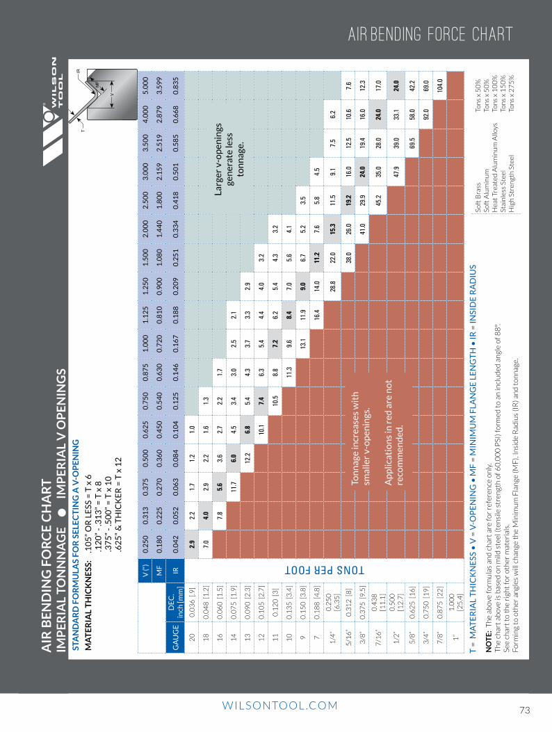
WILSONTOOL.COM WILSONTOOL.COM 73
NON-STANDARD FEATURES ADD ON CHARGES
REF
EREN
CE
TIR
V
MF
AIR
BE
ND
ING
FO
RC
E C
HA
RT
IM
PE
RIA
L TO
NN
NA
GE
I
MP
ER
IAL
V O
PE
NIN
GS
STA
ND
AR
D F
OR
MU
LAS
FO
R S
ELE
CT
ING
A V
-OP
EN
ING
MA
TE
RIA
L T
HIC
KN
ESS
: .
10
5”
OR
LE
SS =
T x
6
.
12
0”
- .3
13
” =
T x
8
.3
75
” -
.50
0”
= T
x 1
0
.
62
5”
& T
HIC
KE
R =
T x
12
NO
TE
: T
he
abov
e fo
rmu
las
and
ch
art
are
for
refe
ren
ce o
nly
.T
he
char
t ab
ove
is b
ased
on
mild
ste
el (t
ensi
le s
tren
gth
of 6
0,0
00
PSI
) fo
rmed
to
an
incl
ud
ed a
ngl
e o
f 88
º.
See
char
t to
th
e ri
ght
for
oth
er m
ater
ials
.
Form
ing
to o
ther
an
gles
will
ch
ange
th
e M
inim
um
Fla
nge
(MF
), In
sid
e R
adiu
s (I
R) a
nd
to
nn
age.
T =
MA
TE
RIA
L T
HIC
KN
ESS
• V
= V
-OP
EN
ING
• M
F =
MIN
IMU
M F
LAN
GE
LE
NG
TH
• IR
= IN
SID
E R
AD
IUS
V (“
)0
.25
00
.31
30
.37
50
.50
00
.62
50
.75
00
.87
51
.00
01
.12
51
.25
01
.50
02
.00
02
.50
03
.00
03
.50
04
.00
05
.00
0
MF
0.1
80
0.2
25
0.2
70
0.3
60
0.4
50
0.5
40
0.6
30
0.7
20
0.8
10
0.9
00
1.0
80
1.4
40
1.8
00
2.1
59
2.5
19
2.8
79
3.5
99
GA
UG
ED
EC
.in
ch [m
m]
IR0
.04
20
.05
20
.06
30
.08
40
.10
40
.12
50
.14
60
.16
70
.18
80
.20
90
.25
10
.33
40
.41
80
.50
10
.58
50
.66
80
.83
5
20
0.0
36
[.9
]
TONS PER FOOT
2.9
2.2
1.7
1.2
1.0
18
0.0
48
[1
.2]
7.0
4.0
2.9
2.2
1.6
1.3
16
0.0
60
[1
.5]
7.8
5.6
3.6
2.7
2.2
1.7
14
0.0
75
[1
.9]
11.7
6.0
4.5
3.4
3.0
2.5
2.1
13
0.0
90
[2
.3]
12.2
6.8
5.4
4.3
3.7
3.3
2.9
12
0.1
05
[2
.7]
10.1
7.4
6.3
5.4
4.4
4.0
3.2
11
0.1
20
[3
]10
.58.
87.
26.
25.
44.
33.
2
10
0.1
35
[3
.4]
11.3
9.6
8.4
7.0
5.6
4.1
90
.15
0 [
3.8
]13
.111
.99.
06.
75.
23.
5
70
.18
8 [
4.8
]16
.414
.011
.27.
65.
84.
5
1/4
”0
.25
0
[6.3
5]
28.8
22.0
15.3
11.5
9.1
7.5
6.2
5/1
6”
0.3
12
[8
]38
.026
.019
.216
.012
.510
.67.
6
3/8
”0
.37
5 [
9.5
]41
.029
.924
.019
.416
.012
.3
7/1
6”
0.4
38
[1
1.1
]45
.235
.028
.024
.017
.0
1/2
”0
.50
0
[12
.7]
47.9
39.0
33.1
24.0
5/8
”0
.62
5 [
16
]69
.558
.042
.2
3/4
”0
.75
0 [
19
]92
.069
.0
7/8
”0
.87
5 [
22
]10
4.0
1”
1.0
00
[2
5.4
]
Soft
Bra
ssSo
ft A
lum
inu
mH
eat
Trea
ted
Alu
min
um
Allo
ysSt
ain
less
Ste
elH
igh
Str
engt
h S
teel
Ton
s x
50
%To
ns
x 5
0%
Ton
s x
10
0%
Ton
s x
15
0%
Ton
s x
27
5%
Ton
nag
e in
crea
ses
wit
h
smal
ler
v-o
pen
ings
.
Ap
plic
atio
ns
in r
ed a
re n
ot
reco
mm
end
ed.
Larg
er v
-op
enin
gs
gen
erat
e le
ss
ton
nag
e.
AIR BENDING FORCE CHART

WILSONTOOL.COM WILSONTOOL.COM74
V
[mm
]4
67
81
01
21
41
61
82
02
53
24
05
06
38
01
00
12
51
60
20
02
50
V(“)
0.1
57
0.2
36
0.2
76
0.3
15
0.3
94
0.4
72
0.5
51
0.6
30
0.7
09
0.7
87
0.9
84
1.2
60
1.5
75
1.9
69
2.4
80
3.1
50
3.9
37
4.9
21
6.2
99
7.8
74
9.8
43
MF
0.1
10
0.1
65
0.1
93
0.2
20
0.2
76
0.3
31
0.3
97
0.4
54
0.5
10
0.5
67
0.7
09
0.9
45
1.1
81
1.4
76
1.8
60
2.3
62
2.9
53
3.7
89
4.8
50
6.0
63
7.5
79
GA
UG
ED
EC
.in
ch [m
m]
IR0
.02
60
.03
90
.04
60
.05
20
.06
60
.07
90
.09
20
.10
50
.11
80
.13
10
.16
40
.21
00
.26
20
.32
80
.41
30
.52
50
.65
60
.82
01
.05
01
.31
21
.64
0
20
0.0
36
[.9]
TONS PER FOOT
5.4
3.6
3.0
2.5
2.0
1.7
18
0.0
48
[1.2
]7
.25
.84
.83
.72
.72
.42
.0
16
0.0
60
[1.5
]7
.86
.05
.04
.23
.53
.12
.7
14
0.0
75
[1.9
]1
1.3
7.5
7.1
5.6
4.8
4.1
3.2
13
0.0
90
[2.3
]1
2.5
10
.18
.27
.25
.43
.7
12
0.1
05
[2.7
]1
5.8
13
.01
0.5
9.5
7.5
5.6
4.0
11
0.1
20
[3]
16
.11
3.1
10
.17
.25
.03
.8
10
0.1
35
[3.4
]1
2.0
8.1
6.2
4.7
3.5
90
.15
0 [3
.8]
13
.19
.06
.75
.2
3/1
60
.18
8 [4
.8]
24
.11
5.0
11
.37
.55
.8
1/4
0.2
50
[6.3
5]
30
.02
0.0
15
.01
0.5
8.5
5/1
60
.31
3 [8
]3
7.6
25
.01
8.8
13
.11
0.0
3/8
0.3
75
[9.5
]3
8.3
28
.12
2.5
15
.01
1.3
1/2
0.5
00
[12
.7]
52
.03
9.0
30
.02
2.0
16
.0
5/8
0.6
25
[16
]7
0.0
52
.53
7.5
27
.52
0.0
15
.0
3/4
0.7
50
[19
]6
6.0
45
.03
2.3
22
.5
11
.00
0 [2
5.4
]9
0.0
60
.04
4.0
1-1
/41
.25
0 [3
2]
10
2.5
75
.0
Ton
nage in
creases with
sm
aller v-op
enin
gs.
Ap
plicatio
ns in
red are n
ot
recom
men
ded
.
NON-STANDARD KEYING , D IE CLEARANCEREFER
ENCE
TIR
V
MF
AIR
BE
ND
ING
FO
RC
E C
HA
RT
IM
PE
RIA
L TON
NA
GE
ME
TR
IC V
OP
EN
ING
S
STAN
DA
RD
FO
RM
ULA
S FO
R SE
LEC
TIN
G A
V-O
PE
NIN
G
MA
TE
RIA
L TH
ICK
NE
SS: 2.6
mm
OR
LESS =
T x 6
3.0
0m
m - 8
.0m
m =
T x 8
9
.00
mm
- 12
.00
mm
= T
x 10
14
.00
mm
& T
HIC
KE
R =
T x 1
2
T =
MA
TE
RIA
L TH
ICK
NE
SS • V
= V
-OP
EN
ING
• M
F =
MIN
IMU
M F
LAN
GE
LEN
GT
H •
IR =
INSID
E R
AD
IUS
Soft B
rassSo
ft Alu
min
um
Heat Treated
Alu
min
um
Alloys
Stainless Steel
High
Strength
Steel
Ton
s x 50
%To
ns x 5
0%
Ton
s x 10
0%
Ton
s x 15
0%
Ton
s x 27
5%
Larger v-op
enin
gs gen
erate less to
nn
age.
NO
TE
: Th
e above fo
rmu
las and
chart are fo
r reference o
nly.
Th
e chart ab
ove is based
on
mild
steel (tensile stren
gth o
f 60
,00
0 P
SI) form
ed to
an in
clud
ed an
gle of 8
8º.
See chart to
the righ
t for o
ther m
aterials. Fo
rmin
g to o
ther an
gles will ch
ange th
e Min
imu
m F
lange (M
F), In
side R
adiu
s (IR) an
d to
nn
age.
AIR BENDING FORCE CHART

WILSONTOOL.COM WILSONTOOL.COM 75
Clamping Innovations - Fast Tool Changes
Whether you’re looking for cost-effective mechanical clamping, simple push-button setups or an ultra-fast hydraulic solution, Wilson Tool has a clamping system to meet your needs.
ExpressRail Hydraulic ClampingThe ExpressRail™ hydraulic clamping system reduces set-up time with a wireless pendant control that clamps and seats your press brake tooling in seconds. This system also gives you more open height and extended clamp life. The ExpressRail hydraulic clamping system works with WT Style or American Precision G Series tooling.
PowerExpress Hydraulic ClampingThe PowerExpress hydraulic clamping system offers easy installation, lightning fast changeouts, long-term reliability and increased bending capacity. Clamp and seat straight-tanged American style tooling in a single operation.
Express ClampsInstantly lock European style press brake punches in place with the push of a lever. Express Clamps are uniquely de-signed to increase your productivity and reduce your operating costs. Available for virtually any make and model of press brake.
EUROPEAN STYLE
WT STYLE
CONVENTIONAL
From standard tooling solutions for American Precision®, European Style, WT Style Precision™ and Con-ventional press brake tooling to customized tooling for the most unique bending applications. Wilson Tool provides the broadest selection of tooling options to press brake fabrica-tors around the world.
Almost 200 years of experience is just a phone call or email away. Our highly trained technical staff has a combined 190 years of experience. Our staff of engineers, designers, and customer support team are highly qualified to find the best tooling solutions for you. From your first inquiry into tooling until your business is more successful than you imagined, we are here to help.

WILSON TOOL INTERNATIONAL
WORLD HEADQUARTERS
Wilson Tool International - United StatesTel (Free): 800-445-4518 Fax (Free): 800-539-4590 Email: [email protected]
NORTH AMERICA
Wilson Tool - CanadaPunching and Stamping Division Tel: 800-268-5573 | Fax: 800-668-9314 Email: [email protected]
Wilson Tool - CanadaPress Brake Division Tel: 800-268-4180 | Fax: 905-840-1032 Email: [email protected]
Wilson Tool - MexicoTel: 52 (81) 8865-4820 | Fax: 52 (81) 8865-4599 Email: [email protected]
SOUTH AMERICA
Wilson Tool - ArgentinaTel: +54 114 799 6519 Email: [email protected]
Milling Ferramentas - BrazilTel/Fax: 55 11 5621-2100 Email: [email protected]
CHINA / PACIFIC RIM
Wilson Tool - ChinaTel: +86 21 51089638 | Fax: +86 21 64422195 Email: [email protected]
EUROPE / MIDEAST / AFRICA
Wilson Tool - United KingdomTel (Free): 0800-373748 | Tel: +44 1793 831818 Fax (Free): 0800-373758 | Fax: +44 1793 831945 or 46 Email: [email protected]
Wilson Tool - GermanyTel (Free): 00800-9457668665 | Tel: +49 5723 747 0 Fax (Free): 00800-945766329 | Fax: +49 5723 747 10 Email: [email protected]
Wilson Tool - DenmarkTel (Free): 80 20 20 24 | Tel: +45 44 53 1699 Fax (Free): 80 20 20 26 | Fax: +45 44 53 0607 Email: [email protected]
Wilson Tool - FranceTel: +33 (0) 164 13 47 80 | Fax: +33 (0) 164 13 47 81 Email: [email protected]
Toolspress - ItalyTel: +39 0521 850510 / 850677 Fax: +39 0521 850796 Email: [email protected]
B351C USA 2016© 2016 Wilson Tool International