Embed Size (px)
Citation preview
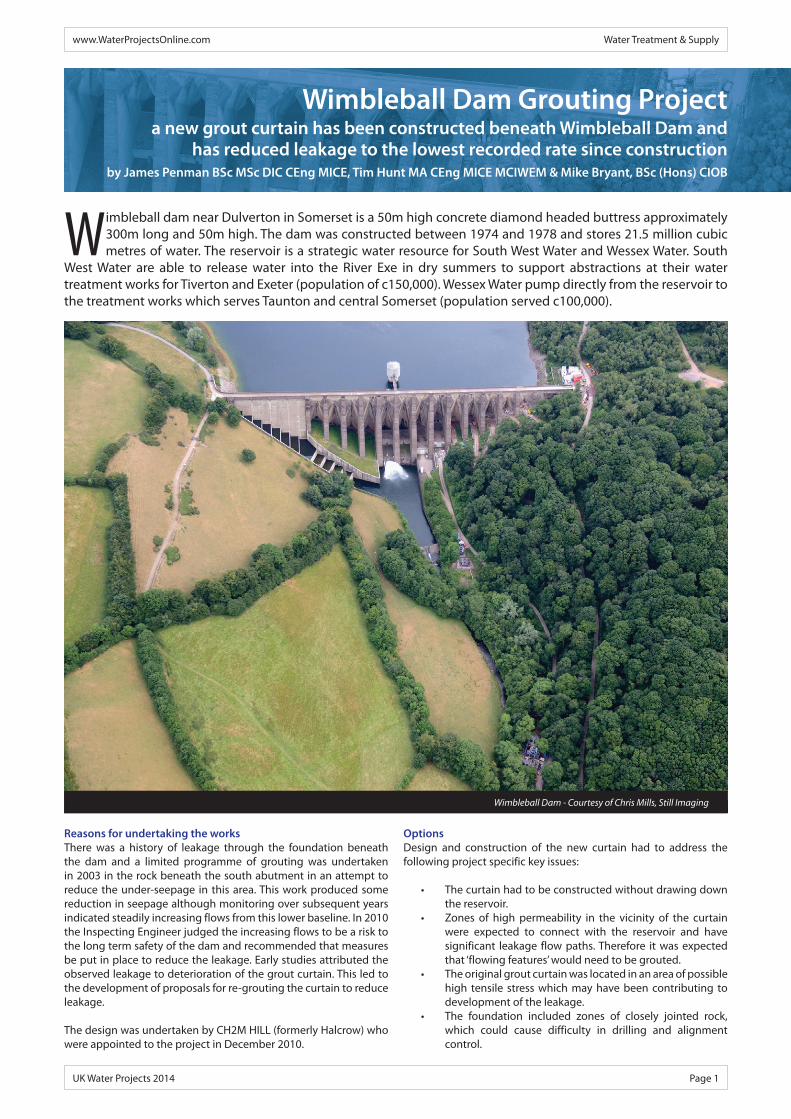
Wimbleball dam near Dulverton in Somerset is a 50m high concrete diamond headed buttress approximately 300m long and 50m high. The dam was constructed between 1974 and 1978 and stores 21.5 million cubic metres of water. The reservoir is a strategic water resource for South West Water and Wessex Water. South
West Water are able to release water into the River Exe in dry summers to support abstractions at their water treatment works for Tiverton and Exeter (population of c150,000). Wessex Water pump directly from the reservoir to the treatment works which serves Taunton and central Somerset (population served c100,000).
Reasons for undertaking the worksThere was a history of leakage through the foundation beneath the dam and a limited programme of grouting was undertaken in 2003 in the rock beneath the south abutment in an attempt to reduce the under-seepage in this area. This work produced some reduction in seepage although monitoring over subsequent years indicated steadily increasing flows from this lower baseline. In 2010 the Inspecting Engineer judged the increasing flows to be a risk to the long term safety of the dam and recommended that measures be put in place to reduce the leakage. Early studies attributed the observed leakage to deterioration of the grout curtain. This led to the development of proposals for re-grouting the curtain to reduce leakage.
The design was undertaken by CH2M HILL (formerly Halcrow) who were appointed to the project in December 2010.
www.WaterProjectsOnline.com Water Treatment & Supply
UK Water Projects 2014 Page 1
Wimbleball Dam Grouting Projecta new grout curtain has been constructed beneath Wimbleball Dam and
has reduced leakage to the lowest recorded rate since constructionby James Penman BSc MSc DIC CEng MICE, Tim Hunt MA CEng MICE MCIWEM & Mike Bryant, BSc (Hons) CIOB
Wimbleball Dam - Courtesy of Chris Mills, Still Imaging
Options Design and construction of the new curtain had to address the following project specific key issues:
• The curtain had to be constructed without drawing down the reservoir.
• Zones of high permeability in the vicinity of the curtain were expected to connect with the reservoir and have significant leakage flow paths. Therefore it was expected that ‘flowing features’ would need to be grouted.
• The original grout curtain was located in an area of possible high tensile stress which may have been contributing to development of the leakage.
• The foundation included zones of closely jointed rock, which could cause difficulty in drilling and alignment control.

For Hire, Sales & Technical Support Call Siltbuster on 01600 772256 or visit www.siltbuster.com
• Lamella Clarifi ers• Biological Treatment Solutions• Dissolved Air Flotation Units• pH Correction
• Filter Media Washing • Chemical Dosing• Filter Presses & Screw Presses• Dissolved Metals Removal
Struggling to source temporary treatment during refurbishment or upgrading of existing works?Siltbuster Process Solutions (SPS) Ltd are the largest supplier of transportable equipment in the wastewater industry priding ourselves on providing a technical solution and not just a product. Our solutions enable works to be taken offl ine at no risk to site discharge consents.
Our Rapidly Deployable Solutions Include:
UK Water Projects 2014.indd 1 16/07/2014 12:10:24
www.WaterProjectsOnline.com Water Treatment & Supply
UK Water Projects 2014 Page 3
Initial studies focused on attempting to renew the existing vertical grout curtain at the upstream toe of the dam. Options considered included grouting from a tunnel driven along the line of the curtain from either a shaft on the south abutment or from access tunnels downstream of the dam passing beneath the dam foundation.
However, this strategy was changed when the stability analysis indicated that the original grout curtain was within a tension zone and that there was an opportunity to move the grout curtain downstream without adversely impacting the stability of the dam.
Moving the curtain downstream allowed an inclined curtain to be constructed on the line of the downstream edge of the buttress head with the curtain inclined upstream at a gradient of 1v:0.4h.
Options for constructing the curtain then included:
• OptionA: driving galleries through the buttress webs and backfill, accessed from a tunnel leading to the downstream toe.
• OptionB: lowering the backfill level between the buttresses and driving galleries though the buttresses at the lowered ground level.
Option B was the lowest cost option in terms of capital expenditure, long term O&M costs and construction time. It had significant safety advantages over the other options including avoiding underground works and confined spaces. Although cased drill holes would be required to reach the grout curtain area, this was offset by being able to use larger, higher power drilling rigs, providing better drilling rates and directional accuracy compared with the smaller rigs required for work underground.
The construction of a new curtain from the downstream side of the dam constrains the alignment of the grout curtain to be parallel to the face of the dam and so inclined across the plane of the existing grout curtain.
Scheme designAfter a review of potential access arrangements for Option B it was concluded that there was no benefit in the excavation of backfill material from between the buttresses as it would be possible to construct access tracks into each bay at close to the existing levels. The additional drilling lengths through the backfill material were considered acceptable.
The initial concept of drilling parallel grout holes along the full length of the curtain required the formation of galleries through the buttresses, which would have been time consuming.
The arrangement was therefore developed into a combination of parallel and inclined holes such that the sections of curtain beneath the buttresses were covered by “crossover” inclined holes drilled from the adjacent bays. At each end of the new curtain there are transitions back to the original curtain.
The design included a planned systematic grouting procedure comprising three series of injection boreholes drilled and grouted successively to progressively ‘tighten’ the ground. This resulted in a final hole spacing of 2m. Each borehole was grouted in multiple stages, varying between 3m and 5m in length, using mainly descending stage grouting.
The design of the works followed state-of-the-art observational techniques to assess and control the quantities of grout to be injected into the ground. The process can be summarised as follows:
• Initial hydrotests, televiewer inspection and geophysical logging of ungrouted boreholes to give information on permeability, fissure frequency and fissure apertures.
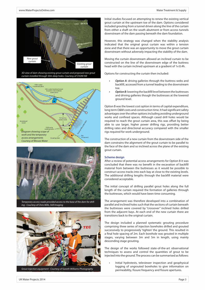
Diagram showing scope of work and the temporary access arrangements Courtesy of Wessex Water
Temporary access roads provided access to the base of the dam for drill-ing - Courtesy of Chris Mills, Still Imaging
3D view of dam showing existing grout curtain and proposed new grout curtain installed through 50m deep holes. Courtesy of CH2M Hill
New groutcurtain
Existing groutcurtain
Grout injection equipment - Courtesy of Gareth Williams Photography

www.WaterProjectsOnline.com Water Treatment & Supply
UK Water Projects 2014 Page 4
• Drilling and grouting a 16m long representative trial curtain segment, adjacent to the new main curtain location, using the selected grout materials and an initial estimate of Grout Intensity Number (GIN) and hole spacing.
• From each Series to the next, the grout take should be seen to diminish, while the final pressure will progressively increase. Increasing pressure from one borehole Series to the next indicates that the first Series has sealed the wider fissures with the following Series sealing the remaining finer fissures. The grouting records form an important part of the validation of the works.
• Confirmation of the overall result by conducting hydrotests in validation holes on the completed grout curtain and adjacent ground to demonstrate the reduction in permeability and width of curtain achieved.
Contractual arrangementsFollowing a competitive tender the contract for the construction works was let to Bachy Soletanche as an NEC Option C contract in December 2012. The contractor and the designer were jointly incentivised against a Target Cost with any savings or increases, up to 15% of the Target cost, being shared in the ratio SWW 50%, contractor 47% and designer 3%.
The contract included an early contractor involvement phase during which the design, and implementation options, were developed jointly by the client, designer and contractor. The final project value was £9.5 million.
ConstructionConstruction works commenced in January 2013 with the site establishment. To provide access for the drilling rigs between the buttresses considerable temporary works were required to re-open the original dam construction routes and provide new temporary access roads.
Site establishment was followed by an initial phase of investigations and trials. The main grouting works commenced in early October 2013 and were substantially complete by the end of April 2014. The main works included:
• 103 (No.) grout holes.• 5,500m of drilling.• 3,500m of drilling in foundations grouted.• 670m3 of grout injected.
Three drilling rigs and two self-contained and automated grout injection units (each capable of up to six simultaneous injections) were used enabling up to 50 grout stages to be completed in a week.
The grout mix was initially developed during earlier laboratory and full scale trials at the contractor’s laboratory in France. The mix was further developed during the on site trials phase to provide a durable and stable grout and comprised a combination of ultrafine cement, silica fume, superplasticiser and water.
The grout injection process was undertaken using the GIN technique and was managed by computer-controlled pumps. The contractor’s software recorded volume, pressure, and flow in real time with pre-set cut off levels for maximum pressure and volume.
In general, the GIN technique advocates the use of a single, stable, fine-grained, cement grout mix of relatively low water:cement ratio. A steady, low to medium rate of injection is maintained, which results in a progressively increasing injection pressure. The rate of pressure increase varies depending on the fissures being injected.
Use of the GIN technique prevents combinations of high pressure and large volumes occurring that can result in uncontrolled
Drill rig - Courtesy of South West Water
S P E C I A L I S T G E O T E C H N I C S
Permeation Grouting
Compensation Grouting
Jet Grouting
Soil Mixing (Wet or Dry)
Compaction & Fissure Grouting
Ground Anchors
Mini Piling
Soil Nailing
Restricted Access Piling
Slurry cut-off Walls & Trenchmix
www.bacsol.co.uk
Camberley Normanton
www.WaterProjectsOnline.com Water Treatment & Supply
UK Water Projects 2014 Page 5
hydraulic jacking and disruption of the rock mass, while at the same time allowing the use of high pressure at low volumes to ensure penetration of fine fissures.
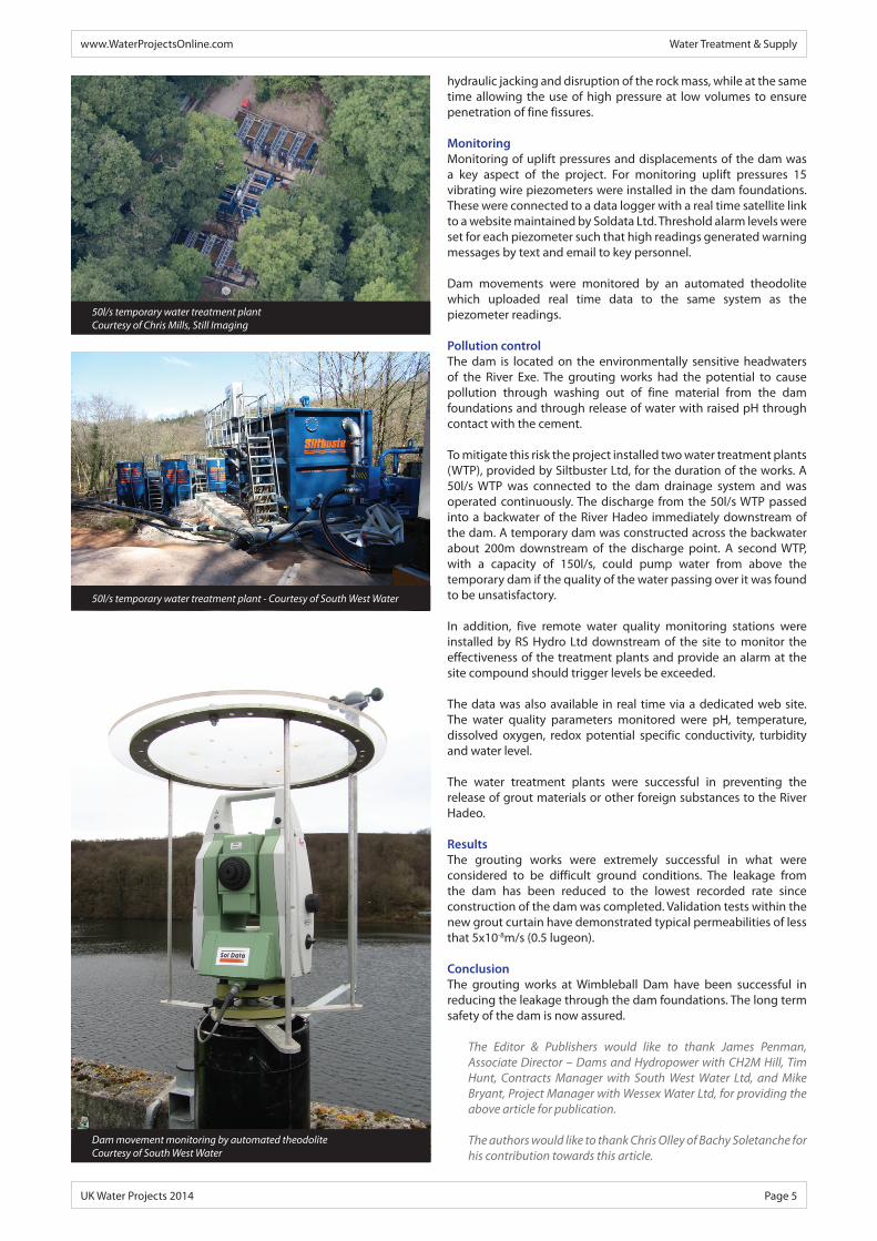
Monitoring Monitoring of uplift pressures and displacements of the dam was a key aspect of the project. For monitoring uplift pressures 15 vibrating wire piezometers were installed in the dam foundations. These were connected to a data logger with a real time satellite link to a website maintained by Soldata Ltd. Threshold alarm levels were set for each piezometer such that high readings generated warning messages by text and email to key personnel.
Dam movements were monitored by an automated theodolite which uploaded real time data to the same system as the piezometer readings.
Pollution controlThe dam is located on the environmentally sensitive headwaters of the River Exe. The grouting works had the potential to cause pollution through washing out of fine material from the dam foundations and through release of water with raised pH through contact with the cement.
To mitigate this risk the project installed two water treatment plants (WTP), provided by Siltbuster Ltd, for the duration of the works. A 50l/s WTP was connected to the dam drainage system and was operated continuously. The discharge from the 50l/s WTP passed into a backwater of the River Hadeo immediately downstream of the dam. A temporary dam was constructed across the backwater about 200m downstream of the discharge point. A second WTP, with a capacity of 150l/s, could pump water from above the temporary dam if the quality of the water passing over it was found to be unsatisfactory.
In addition, five remote water quality monitoring stations were installed by RS Hydro Ltd downstream of the site to monitor the effectiveness of the treatment plants and provide an alarm at the site compound should trigger levels be exceeded.
The data was also available in real time via a dedicated web site. The water quality parameters monitored were pH, temperature, dissolved oxygen, redox potential specific conductivity, turbidity and water level.
The water treatment plants were successful in preventing the release of grout materials or other foreign substances to the River Hadeo.
ResultsThe grouting works were extremely successful in what were considered to be difficult ground conditions. The leakage from the dam has been reduced to the lowest recorded rate since construction of the dam was completed. Validation tests within the new grout curtain have demonstrated typical permeabilities of less that 5x10⁻⁸m/s (0.5 lugeon).
ConclusionThe grouting works at Wimbleball Dam have been successful in reducing the leakage through the dam foundations. The long term safety of the dam is now assured.
The Editor & Publishers would like to thank James Penman, Associate Director – Dams and Hydropower with CH2M Hill, Tim Hunt, Contracts Manager with South West Water Ltd, and Mike Bryant, Project Manager with Wessex Water Ltd, for providing the above article for publication.
The authors would like to thank Chris Olley of Bachy Soletanche for his contribution towards this article.
Dam movement monitoring by automated theodoliteCourtesy of South West Water
50l/s temporary water treatment plant - Courtesy of South West Water
50l/s temporary water treatment plantCourtesy of Chris Mills, Still Imaging