Embed Size (px)
Citation preview
Wind action on small sky observatory ScopeDome
A.Flagaa, G. Bosaka, Ł. Flagab, G. Kimbara, M. Floreka
aWind Engineering Laboratory, Cracow University of Technology, Cracow, Poland, [email protected]
aDepartment of Architecture, Lublin University of Technology, Lublin, Poland, [email protected]
1 INTRODUCTION
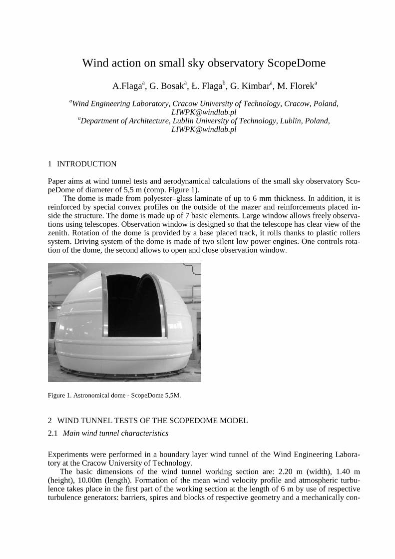
Paper aims at wind tunnel tests and aerodynamical calculations of the small sky observatory Sco-peDome of diameter of 5,5 m (comp. Figure 1).
The dome is made from polyester–glass laminate of up to 6 mm thickness. In addition, it is reinforced by special convex profiles on the outside of the mazer and reinforcements placed in-side the structure. The dome is made up of 7 basic elements. Large window allows freely observa-tions using telescopes. Observation window is designed so that the telescope has clear view of the zenith. Rotation of the dome is provided by a base placed track, it rolls thanks to plastic rollers system. Driving system of the dome is made of two silent low power engines. One controls rota-tion of the dome, the second allows to open and close observation window.
Figure 1. Astronomical dome - ScopeDome 5,5M.
2 WIND TUNNEL TESTS OF THE SCOPEDOME MODEL
2.1 Main wind tunnel characteristics
Experiments were performed in a boundary layer wind tunnel of the Wind Engineering Labora-tory at the Cracow University of Technology.
The basic dimensions of the wind tunnel working section are: 2.20 m (width), 1.40 m (height), 10.00m (length). Formation of the mean wind velocity profile and atmospheric turbu-lence takes place in the first part of the working section at the length of 6 m by use of respective turbulence generators: barriers, spires and blocks of respective geometry and a mechanically con-
trolled height. In the working section of the tunnel there is a round rotational table of 2 m in di-ameter which makes possible the change of a wind inflow direction on the examined model.
2.2 Decsription of the ScopeDome model
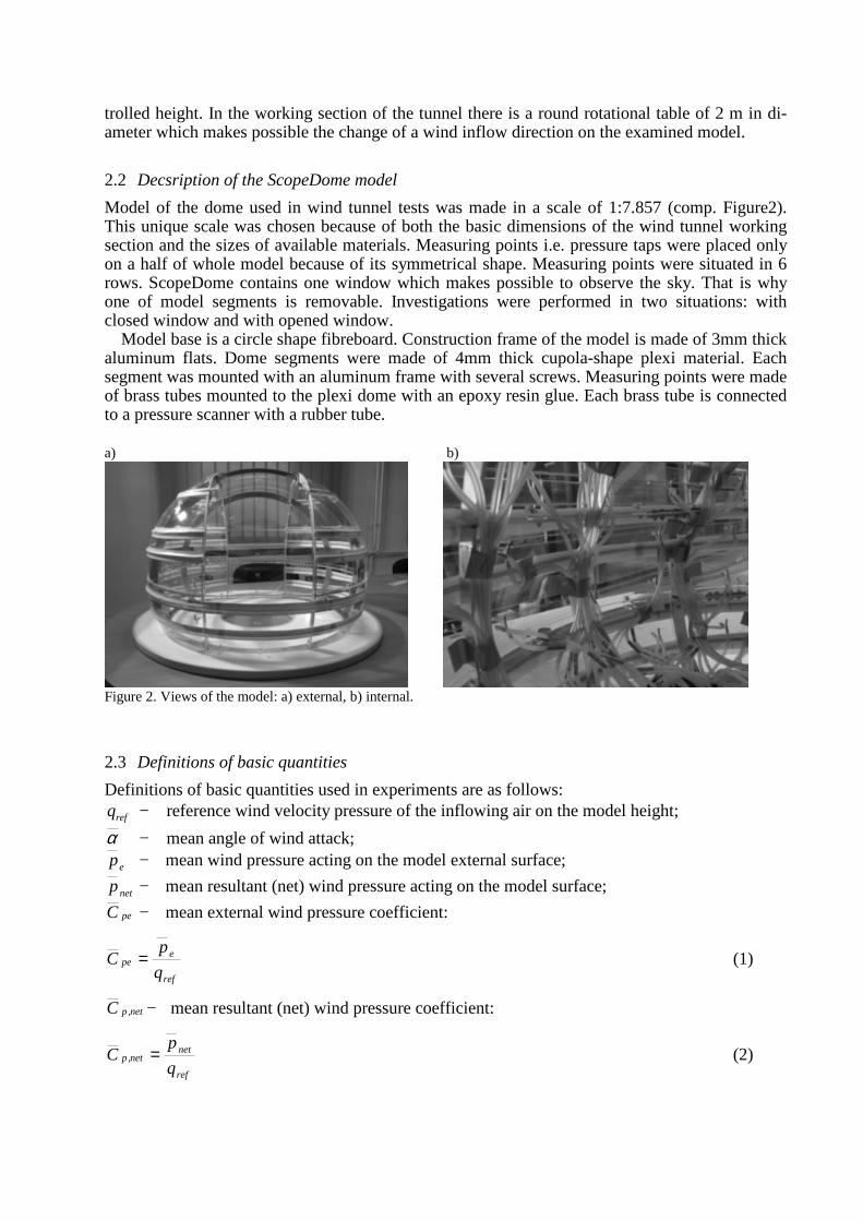
Model of the dome used in wind tunnel tests was made in a scale of 1:7.857 (comp. Figure2). This unique scale was chosen because of both the basic dimensions of the wind tunnel working section and the sizes of available materials. Measuring points i.e. pressure taps were placed only on a half of whole model because of its symmetrical shape. Measuring points were situated in 6 rows. ScopeDome contains one window which makes possible to observe the sky. That is why one of model segments is removable. Investigations were performed in two situations: with closed window and with opened window.
Model base is a circle shape fibreboard. Construction frame of the model is made of 3mm thick aluminum flats. Dome segments were made of 4mm thick cupola-shape plexi material. Each segment was mounted with an aluminum frame with several screws. Measuring points were made of brass tubes mounted to the plexi dome with an epoxy resin glue. Each brass tube is connected to a pressure scanner with a rubber tube. a) b)
Figure 2. Views of the model: a) external, b) internal.
2.3 Definitions of basic quantities
Definitions of basic quantities used in experiments are as follows:
refq − reference wind velocity pressure of the inflowing air on the model height;
α − mean angle of wind attack;
ep − mean wind pressure acting on the model external surface;
netp − mean resultant (net) wind pressure acting on the model surface;
peC − mean external wind pressure coefficient:
ref
epe
q
pC = (1)
net,pC − mean resultant (net) wind pressure coefficient:
ref
netnet,p
q
pC = (2)
2.4 Brief description of wind tunnel tests and exemplary results
Two measurement situations were taken under considerations. In the first one, the dome was closed and characterized by rotational symmetry. Then, as a result, only one wind direction was considered during tunnel tests. In the second measurement situation, the dome was opened and had only one symmetry plane. In order to estimate pressure distributions on the whole model sur-face, the examinations had to be carried out in the full range of the wind inflow directions, which was made with the step of 15o.
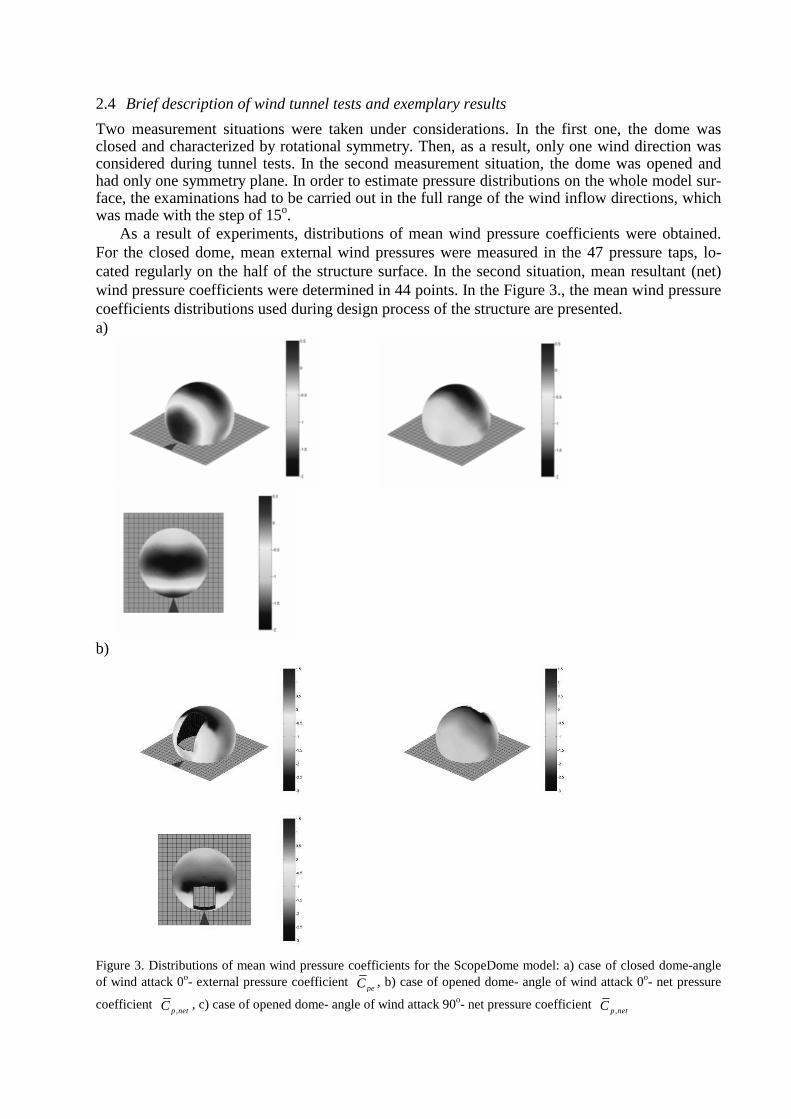
As a result of experiments, distributions of mean wind pressure coefficients were obtained. For the closed dome, mean external wind pressures were measured in the 47 pressure taps, lo-cated regularly on the half of the structure surface. In the second situation, mean resultant (net) wind pressure coefficients were determined in 44 points. In the Figure 3., the mean wind pressure coefficients distributions used during design process of the structure are presented. a)
b)
Figure 3. Distributions of mean wind pressure coefficients for the ScopeDome model: a) case of closed dome-angle of wind attack 0o- external pressure coefficient
peC , b) case of opened dome- angle of wind attack 0o- net pressure
coefficient ,p netC , c) case of opened dome- angle of wind attack 90o- net pressure coefficient
,p netC
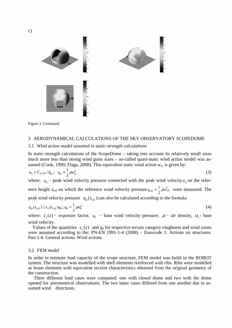
c)
Figure 3. Continued
3 AERODYNAMICAL CALCULATIONS OF THE SKY OBSERVATORY SCOPEDOME
3.1 Wind action model assumed in static-strength calculations
In static-strength calculations of the ScopeDome – taking into account its relatively small sizes much more less than strong wind gusts sizes – so-called quasi-static wind action model was as-sumed (Cook, 1990; Flaga, 2008). This equivalent static wind action we, is given by:
pnetpe qCw ⋅= , ; 2
2
1ppq ρυ= (3)
where: pq − peak wind velocity pressure connected with the peak wind velocity pυ on the refer-
ence height zref on which the reference wind velocity pressure 2
2
1refrefq υρ= were measured. The
peak wind velocity pressure ( )p refq z can also be calculated according to the formula:
breferefp qzczq )()( ≅ ; 2
21
bbq ρυ= (4)
where: )(zce − exposure factor, bq − base wind velocity pressure; ρ − air density, bυ - base
wind velocity. Values of the quantities )(zce and qb for respective terrain category roughness and wind zones
were assumed according to the: PN-EN 1991-1-4 (2008) − Eurocode 1: Actions on structures. Part 1-4. General actions. Wind actions.
3.2 FEM model
In order to estimate load capacity of the scope structure, FEM model was build in the ROBOT system. The structure was modelled with shell elements reinforced with ribs. Ribs were modelled as beam elements with equivalent section characteristics obtained from the original geometry of the construction.
Three different load cases were computed: one with closed dome and two with the dome opened for astronomical observations. The two latter cases differed from one another due to as-sumed wind directions.
In purpose of redesigning of the construction support system, the distribution of reactions was also estimated. In the performed analysis the whole bottom ring of the construction was fixed by boundary conditions. Simplifying assumption was made that in any particular position of the dome the resultant force acting on a single support is an integral of the distributed force at bottom ring over the range of adjacent halves of the spans between supports. Thereafter, an envelope of this results was obtained in regard to different positions of the support.
3.3 Exemplary calculation results
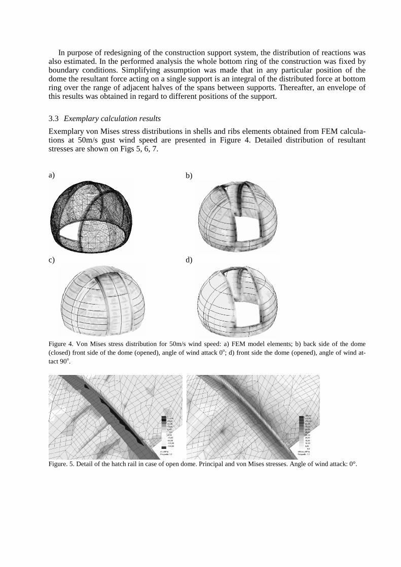
Exemplary von Mises stress distributions in shells and ribs elements obtained from FEM calcula-tions at 50m/s gust wind speed are presented in Figure 4. Detailed distribution of resultant stresses are shown on Figs 5, 6, 7. a)
b)
c)
d)
Figure 4. Von Mises stress distribution for 50m/s wind speed: a) FEM model elements; b) back side of the dome (closed) front side of the dome (opened), angle of wind attack 0o; d) front side the dome (opened), angle of wind at-tact 90o.
Figure. 5. Detail of the hatch rail in case of open dome. Principal and von Mises stresses. Angle of wind attack: 0°.
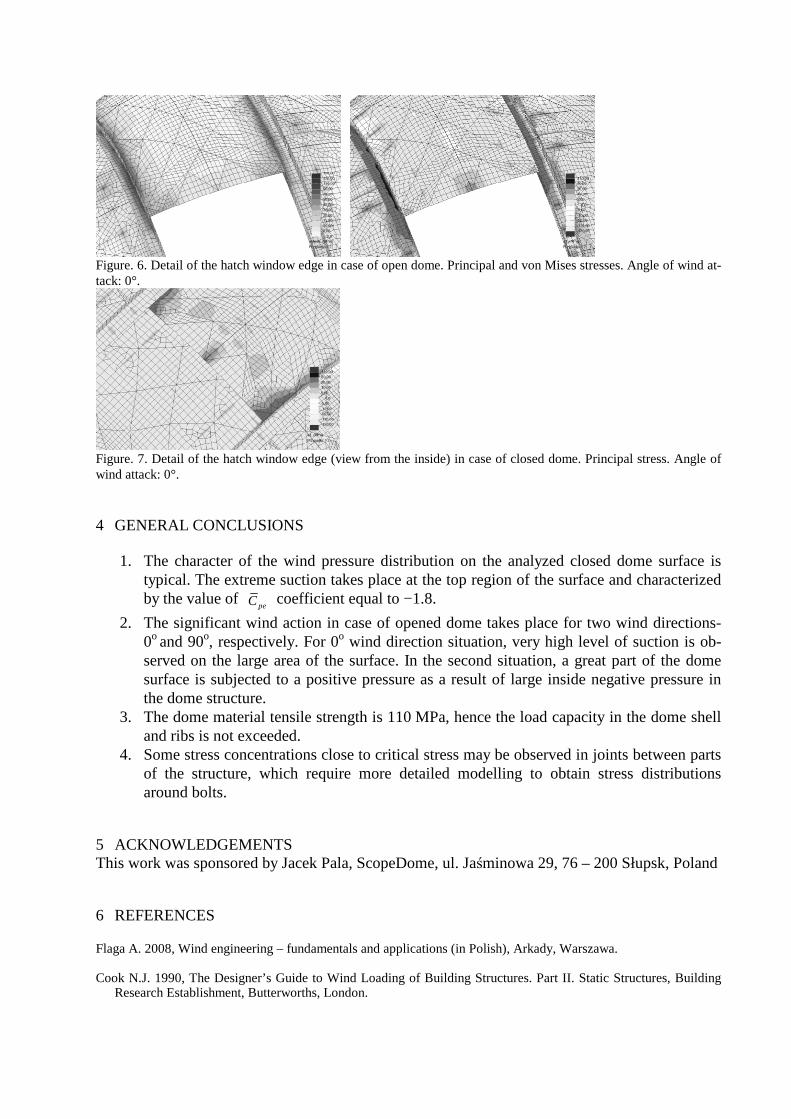
Figure. 6. Detail of the hatch window edge in case of open dome. Principal and von Mises stresses. Angle of wind at-tack: 0°.
Figure. 7. Detail of the hatch window edge (view from the inside) in case of closed dome. Principal stress. Angle of wind attack: 0°.
4 GENERAL CONCLUSIONS 1. The character of the wind pressure distribution on the analyzed closed dome surface is
typical. The extreme suction takes place at the top region of the surface and characterized by the value of
peC coefficient equal to −1.8.
2. The significant wind action in case of opened dome takes place for two wind directions- 0o and 90o, respectively. For 0o wind direction situation, very high level of suction is ob-served on the large area of the surface. In the second situation, a great part of the dome surface is subjected to a positive pressure as a result of large inside negative pressure in the dome structure.
3. The dome material tensile strength is 110 MPa, hence the load capacity in the dome shell and ribs is not exceeded.
4. Some stress concentrations close to critical stress may be observed in joints between parts of the structure, which require more detailed modelling to obtain stress distributions around bolts.
5 ACKNOWLEDGEMENTS This work was sponsored by Jacek Pala, ScopeDome, ul. Jaśminowa 29, 76 – 200 Słupsk, Poland
6 REFERENCES
Flaga A. 2008, Wind engineering – fundamentals and applications (in Polish), Arkady, Warszawa. Cook N.J. 1990, The Designer’s Guide to Wind Loading of Building Structures. Part II. Static Structures, Building
Research Establishment, Butterworths, London.


![Night sky photometry and spectroscopy performed … · arXiv:1304.7716v1 [astro-ph.IM] 29 Apr 2013 Night sky photometry and spectroscopy performed at the Vienna University Observatory](https://img.pdfslide.net/doc/110x75/5b9f1e6209d3f26e288c575d/night-sky-photometry-and-spectroscopy-performed-arxiv13047716v1-astro-phim.jpg)