Embed Size (px)
Citation preview

WIN
D
T H E W O R L D O F W E A T H E R D A T A
THE WORLD OF WEATHER DATAMeasurement and Documentation:Thies’ range of service for meteorology, environmental protection and industry
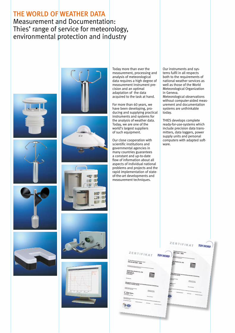
Today more than ever the measurement, processing and analysis of meteorological data requires a high degree of measurement instrument pre-cision and an optimal adaptation of the data acquired to the task at hand.
For more than 60 years, we have been developing, pro-ducing and supplying practical instruments and systems for the analysis of weather data.Today, we are one of theworld’s largest suppliers of such equipment.
Our close cooperation with scientific institutions and governmental agencies in many countries guarantees a constant and up-to-date flow of information about all aspects of individual national problems and projects and the rapid implementation of state-of-the-art developments and measurement techniques.
Our instruments and sys-tems fulfil in all respects both to the requirements of national weather services as well as those of the World Meteorological Organization in Geneva.Meteorological observations without computer-aided meas-urement and documentation systems are unthinkable today.
THIES develops complete ready-for-use-systems which include precision data trans-mitters, data loggers, power supply units and personal computers with adapted soft-ware.
Glossary . . . . . . . . . . . . . . . . . . . . . . . . . . . . . . . . . . . . . . . . . . . . . . 2
Ultrasonic Anemometer . . . . . . . . . . . . . . . . . . . . . . . . . . . . . . . . . . . . . 5
First Class (Anemometer and Wind Direction Transmitter) . . . . . . . . . . . . . . . . . 17
Classic (Anemometer and Wind Direction Transmitter) . . . . . . . . . . . . . . . . . . . 25
Compact (Anemometer and Wind Direction Transmitter) . . . . . . . . . . . . . . . . . . 31
Cold Climate (Anemometer, Wind Transmitters and Wind Direction Transmitters) . . . . 37
Small Wind Transmitters . . . . . . . . . . . . . . . . . . . . . . . . . . . . . . . . . . . . 41
Wind Transmitters for Air Flow . . . . . . . . . . . . . . . . . . . . . . . . . . . . . . . . . 43
Hand Instruments, Mechanical Anemometer . . . . . . . . . . . . . . . . . . . . . . . . . 45
Integrated Sensors: METEO comp, Clima Sensor, Weather Station . . . . . . . . . . . . 47
Messuring Transformers . . . . . . . . . . . . . . . . . . . . . . . . . . . . . . . . . . . . 53
Indicators, Records, Software . . . . . . . . . . . . . . . . . . . . . . . . . . . . . . . . . . 55
Wind Alarm . . . . . . . . . . . . . . . . . . . . . . . . . . . . . . . . . . . . . . . . . . . . 63
Masts and Mechanical Accessories . . . . . . . . . . . . . . . . . . . . . . . . . . . . . . 65
Power Supply . . . . . . . . . . . . . . . . . . . . . . . . . . . . . . . . . . . . . . . . . . . 71
Wind Table of Contents
NEW
2
Wind Glossary
Damping coefficient The damping coefficient characterises the oscillations of the wind vane . It is an important characteristic quantity for the qualitative evaluation of the wind vane . The damping coefficient is determined from the amplitudes of two successive excursions and is calculated by means of an equation .
Damping ratio Measure for the damping of wind vanes . It represents the ratio
between the consecutive damped deflection amplitudes (for example 3rd amplitude to 1st amplitude) in one direction .
Wind run The path covered by the wind for a certain period of time .
Delay distance The path covered by the wind which is reached when, after a sudden change in wind speed, the speed reaches 63% of its end value . Stress Maximum allowable wind speed at which no damage occurs on the
wind measuring instruments .
Wind force ”Beaufort“ (bft) classes for certain wind speed ranges .
bft m/s bft m/s 0 0 - 0 .2 9 20 .8 - 24 .4 1 0 .3 - 1 .5 10 24 .5 - 28 .4 2 1 .6 - 3 .3 11 28 .5 - 32 .6 3 3 .4 - 5 .4 12 32 .7 - 36 .9 4 5 .5 - 7 .9 13 37 .0 - 41 .4 5 8 .0 - 10 .7 14 41 .5 - 46 .1 6 10 .8 - 13 .8 15 46 .2 - 50 .9 7 13 .9 - 17 .1 16 51 .0 - 56 .0 8 17 .2 - 20 .7 17 56 .1 - 61 .2
Wind speed The most common units of measurement are: 1 m/s = 3 .6 km/h = 1 .9455 knots
Wind direction Information on the direction from which the wind is coming . Information appears clockwise from North to East (90°), South (180°), West (270°) and North (360°) . Starting value The wind speed at which a cup anemometer respectively the wind vane starts to move .
Detection limit The lowest value of wind speed and wind direction at which a stable value sets in .
Variation The range within which wind direction has changed within the preceding 10 minutes (in accordance with ICAO) .
Gliding mean value The mean value which is updated as the mean value time at short time intervals . (for example the 10 min .-mean value is updated once a second )
3
Wind Glossary
Arithmetic mean value The quotient from the sum of all the individual values and the number of values within the mean value time .
Vectorial mean value Method of calculation: The individual vectors, measured as wind speed and direction, are decomposed into rectangular components . The components are averaged arithmetically, these mean values are then composed into a vectorial mean value .
Vectorial mean value Only used for wind direction . A constant wind speed is assumed for the with standard vectors individual vectors . Orthogonal A straight line standing vertically to another straight line . By arrangingWind velocity vector two measurement distances standing vertically on each others you
achieve the amount and angle of the wind velocity vector in the form of rectangular components . After measurement of the rectangular wind velocity components the amount and angle of the wind velocity can be calculated .
Scalar wind velocity Wind velocity amount without indication of direction Acoustic virtual temperature The acoustic virtual temperature is the air temperature referred to dry
air without any portion of water vapour . It is acquired by propagation measurements of sonic pulses . After
respective correction of the humidity influence the procedure exceeds the accuracy of the classic procedures of the temperature measurement in a weather and thermal radiation shield .
Gray-code One-increment binary code, on the changeover of one value to the next
one only one single data bit modifies each to the previous and the next value respectively . The Gray-code is used for the digital determination of distances, for ex . the wind direction of a wind vane .
The code can be set up by means of any number of digits, it depends only on the required accuracy of resolution .
8-bit wind direction Gray-code The wind direction (0 … 360°) is converted into an 8 bit Gray code
(Thies special) and transmitted . The resolution is 2,5°, 144 increments per revolution .
Increment 0 = 0° = North and corresponds to the sector 0 … 2 .5° Increment 143 = 357 .5° corresponds to the sector 357 .5 … 0° . Serial-synchron. output The serial-synchronous interface is a unidirectional two-wire-interface
with Thies specifications . It allows the connection between Thies wind sensors with serial-synchronous output and respective periphery (for ex . display instruments)

4
Your Notice
5
Wind Ultrasonic Anemometer
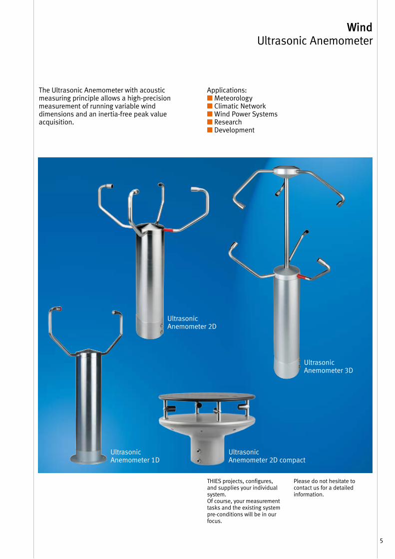
The Ultrasonic Anemometer with acoustic measuring principle allows a high-precision measurement of running variable wind dimensions and an inertia-free peak value acquisition .
THIES projects, configures, and supplies your individual system .Of course, your measurement tasks and the existing system pre-conditions will be in our focus .
Please do not hesitate to contact us for a detailed information .
Ultrasonic Anemometer 3D
Ultrasonic Anemometer 2D
Ultrasonic Anemometer 1D
Ultrasonic Anemometer 2D compact
Applications:■ Meteorology■ Climatic Network■ Wind Power Systems■ Research■ Development
6
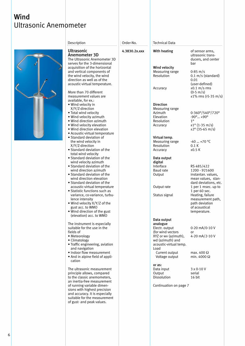
UltrasonicAnemometer 3DThe Ultrasonic Anemometer 3D serves for the 3-dimensional acquisition of the horizontal and vertical components of the wind velocity, the wind direction as well as of the acoustic-virtual temperature .
More than 70 different measurement values are available, for ex .:• Wind velocity in
X/Y/Z-direction• Total wind velocity• Wind velocity azimuth• Wind direction azimuth• Wind velocity elevation• Wind direction elevation• Acoustic-virtual temperature • Standard deviation of
the wind velocity in X/Y/Z-direction
• Standard deviation of the total wind velocity
• Standard deviation of the wind velocity azimuth
• Standard deviation of the wind direction azimuth
• Standard deviation of the wind direction elevation
• Standard deviation of the acoustic-virtual temperature
• Statistic functions such as variance, co-variance, turbu-lence intensity
• Wind velocity X/Y/Z of the gust acc . to WMO
• Wind direction of the gust (elevation) acc . to WMO
The instrument is especially suitable for the use in the fields of• Meteorology• Climatology• Traffic engineering, aviation
and navigation• Indoor flow measurement• And in alpine field of appli-
cation
The ultrasonic measurement principle allows, compared to the classic anemometers, an inertia-free measurement of running variable dimen-sions with highest precision and accuracy . It is especially suitable for the measurement of gust- and peak values .
4.3830 .2x.xxx
With heating
Wind velocityMeasuring rangeResolution
Accuracy
DirectionMeasuring rangeAzimuthElevationResolutionAccuracy
Virtual temp .Measuring rangeResolutionAccuracy
Data output digitalInterfaceBaud rate Output
Output rate
Status signal
Data output analogueElectr . output(for wind vectors XYZ or wv (azimuth), wd (azimuth) and acoustic-virtual temp .Load Current output Voltage output
or as:Data inputOutputDissolution
of sensor arms,ultrasonic trans-ducers, and center bar
0-85 m/s0 .1 m/s (standard)0 .01(user-defined)±0 .1 m/s rms(0-5 m/s)±1% rms (>5-35 m/s)
0-360°/540°/720°-90°… +90°1°±1° (1-35 m/s)±2° (35-65 m/s)
-40 … +70 °C0 .1 K±0 .5 K
RS 485/4221200 - 921600instantan . values,mean values, stan-dard deviations, etc .1 per 1 msec . up to1 per 60 sec .Heating, failure measurement path, path deviation of acoustical temperature .
0-20 mA/0-10 Vor4-20 mA/2-10 V
max . 400 Ωmin . 4000 Ω
3 x 0-10 Vserial16 bit
Description Order-No . Technical Data
Wind Ultrasonic Anemometer
Continuation on page 7
7
Wind Ultrasonic Anemometer
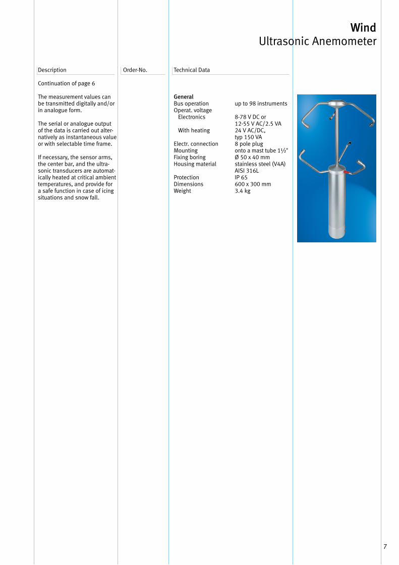
Continuation of page 6 The measurement values can be transmitted digitally and/or in analogue form .
The serial or analogue output of the data is carried out alter-natively as instantaneous value or with selectable time frame .
If necessary, the sensor arms, the center bar, and the ultra-sonic transducers are automat-ically heated at critical ambient temperatures, and provide for a safe function in case of icingsituations and snow fall .
Description Order-No . Technical Data
GeneralBus operationOperat . voltage Electronics
With heating
Electr . connectionMountingFixing boringHousing material
ProtectionDimensionsWeight
up to 98 instruments
8-78 V DC or12-55 V AC/2 .5 VA24 V AC/DC, typ 150 VA8 pole plugonto a mast tube 1½"Ø 50 x 40 mmstainless steel (V4A) AISI 316LIP 65600 x 300 mm3 .4 kg
8
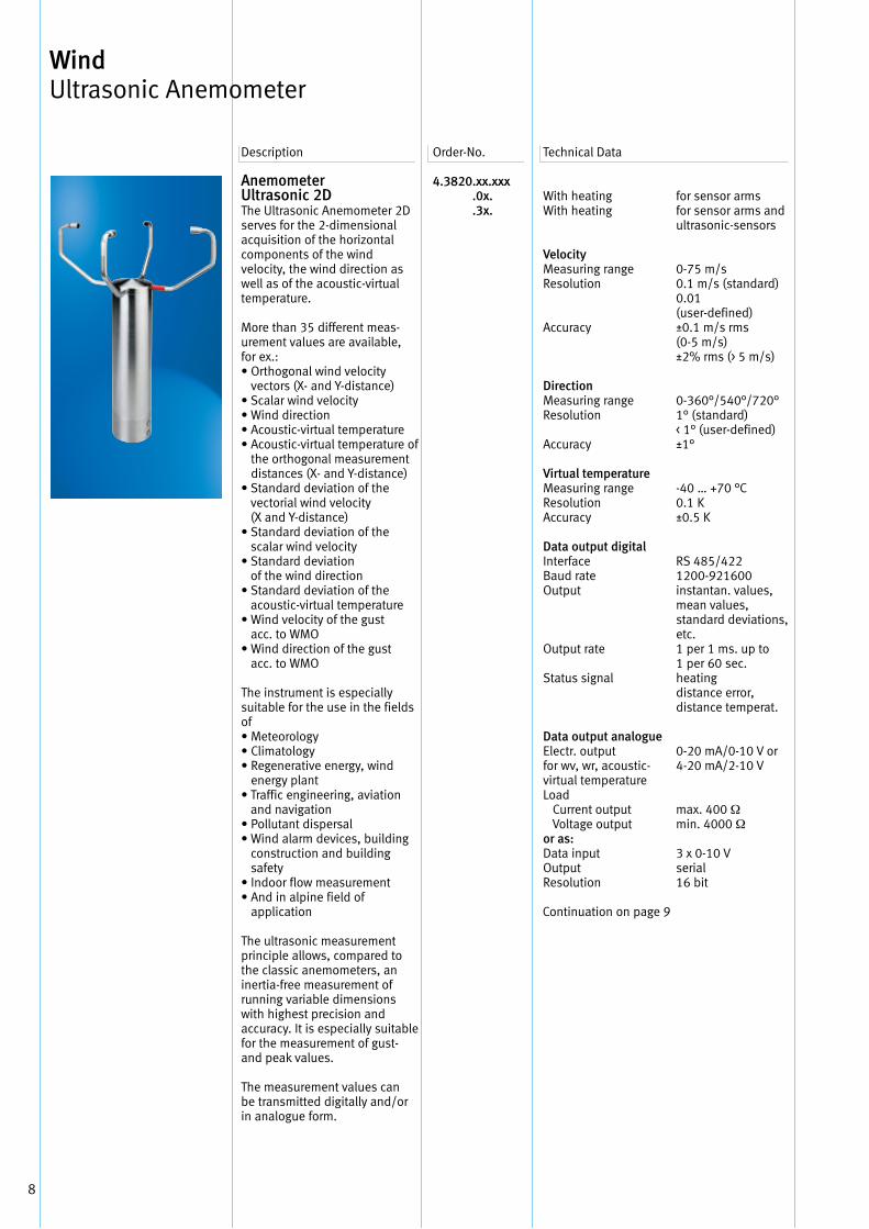
Anemometer Ultrasonic 2DThe Ultrasonic Anemometer 2D serves for the 2-dimensional acquisition of the horizontal components of the wind velocity, the wind direction as well as of the acoustic-virtual temperature .
More than 35 different meas-urement values are available, for ex .:• Orthogonal wind velocity
vectors (X- and Y-distance)• Scalar wind velocity• Wind direction• Acoustic-virtual temperature • Acoustic-virtual temperature of
the orthogonal measurement distances (X- and Y-distance)
• Standard deviation of the vectorial wind velocity (X and Y-distance)
• Standard deviation of the scalar wind velocity
• Standard deviation of the wind direction
• Standard deviation of the acoustic-virtual temperature
• Wind velocity of the gust acc . to WMO
• Wind direction of the gust acc . to WMO
The instrument is especially suitable for the use in the fields of• Meteorology• Climatology• Regenerative energy, wind
energy plant• Traffic engineering, aviation
and navigation• Pollutant dispersal• Wind alarm devices, building
construction and building safety
• Indoor flow measurement• And in alpine field of
application
The ultrasonic measurement principle allows, compared to the classic anemometers, an inertia-free measurement of running variable dimensions with highest precision and accuracy . It is especially suitable for the measurement of gust- and peak values .
The measurement values can be transmitted digitally and/or in analogue form .
4.3820 .xx.xxx .0x. .3x.
With heatingWith heating
VelocityMeasuring rangeResolution
Accuracy
DirectionMeasuring range Resolution
Accuracy
Virtual temperatureMeasuring rangeResolutionAccuracy
Data output digital InterfaceBaud rateOutput
Output rate
Status signal
Data output analogueElectr . outputfor wv, wr, acoustic-virtual temperatureLoad Current output Voltage outputor as: Data input Output Resolution
for sensor armsfor sensor arms and ultrasonic-sensors
0-75 m/s0 .1 m/s (standard)0 .01(user-defined)±0 .1 m/s rms(0-5 m/s)±2% rms (> 5 m/s)
0-360°/540°/720°1° (standard)< 1° (user-defined)±1°
-40 … +70 °C0 .1 K±0 .5 K
RS 485/4221200-921600instantan . values,mean values,standard deviations,etc .1 per 1 ms . up to1 per 60 sec .heatingdistance error,distance temperat .
0-20 mA/0-10 V or4-20 mA/2-10 V
max . 400 Ωmin . 4000 Ω
3 x 0-10 V serial 16 bit
Description Order-No . Technical Data
Wind Ultrasonic Anemometer
Continuation on page 9
9
Wind Ultrasonic Anemometer
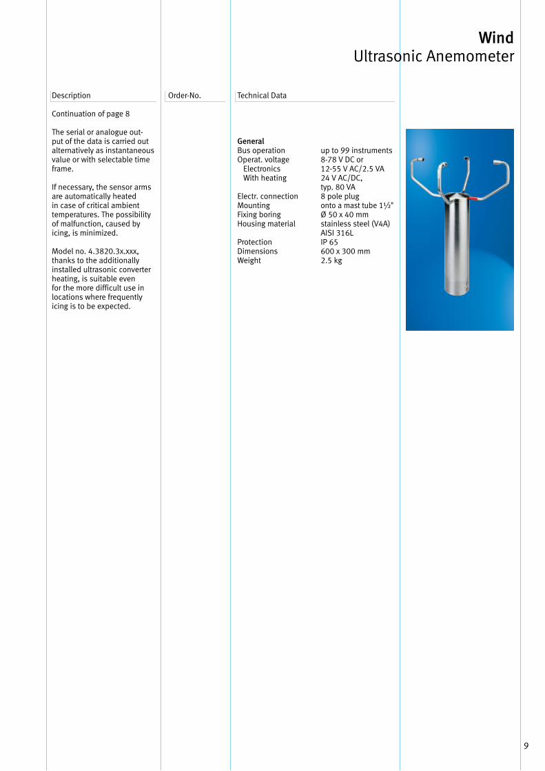
Continuation of page 8
The serial or analogue out-put of the data is carried out alternatively as instantaneous value or with selectable time frame .
If necessary, the sensor arms are automatically heated in case of critical ambient temperatures . The possibility of malfunction, caused by icing, is minimized .
Model no . 4 .3820 .3x .xxx, thanks to the additionally installed ultrasonic converter heating, is suitable even for the more difficult use in locations where frequently icing is to be expected .
Description Order-No . Technical Data
General Bus operation Operat . voltage Electronics With heating
Electr . connection MountingFixing boring Housing material
Protection Dimensions Weight
up to 99 instruments 8-78 V DC or12-55 V AC/2 .5 VA 24 V AC/DC, typ . 80 VA8 pole plug onto a mast tube 1½"Ø 50 x 40 mm stainless steel (V4A) AISI 316L IP 65 600 x 300 mm 2 .5 kg
10
Description Order-No . Technical Data
Technical Data
Wind Ultrasonic Anemometer
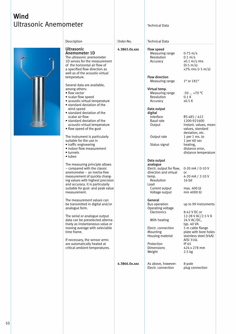
Ultrasonic Anemometer 1DThe ultrasonic anemometer1D serves for the measurement of the horizontal air flow of a specified flow direction as well as of the acoustic-virtual temperature .
Several data are available, among others:• flow vector• scalar flow speed• acoustic-virtual temperature• standard deviation of the
wind speed• standard deviation of the
scalar air flow• standard deviation of the
acoustic-virtual temperature• flow speed of the gust
The instrument is particularly suitable for the use in• traffic engineering• indoor flow measurement• tunnels• tubes
The measuring principle allows – compared with the classic anemometer – an inertia-free measurement of quickly chang-ing values with highest precision and accuracy . It is particularly suitable for gust- and peak value measurement .
The measurement values can be transmitted in digital and/or analogue form .
The serial or analogue output data can be preselected alterna-tively as instantaneous value or moving average with selectable time frame .
If necessary, the sensor arms are automatically heated at critical ambient temperatures .
4.3865.0x.xxx
4.3866.0x.xxx
Flow speed Measuring range Resolution Accuracy
Flow direction Measuring range
Virtual temp. Measuring range Resolution Accuracy
Data output digital Interface Baud rate Output
Output rate
Status signal
Data output analogueElectr . output for flow,direction and virtual temp . ResolutionLoad Current output Voltage output
General Bus operation Operating voltage Electronics
With heating
Electr . connectionMountingHousing material
Protection Dimensions Weight
As above, however: Electr . connection
0-75 m/s0 .1 m/s±0 .1 m/s rms(0-5 m/s)±2% rms (> 5 m/s)
1° or 181°
-50 . . . +70 °C 0 .1 K±0 .5 K
RS 485 / 4221200-921600instant . values, mean values, standard deviation, etc .1 per 1 ms . to1 per 60 sec heating, distance error, distance temperature
0-20 mA / 0-10 Vor4-20 mA / 2-10 V16 bit
max . 400 Ωmin 4000 Ω
up to 99 instruments
8-42 V DC or12-28 V AC/2 .5 V A24 V AC/DC, typ . 40 VA5 m cable flange plate with bore holesstainless steel (V4A) AISI 316LIP 65424 x 278 mm2 .5 kg
8-poleplug connection
11
Wind Ultrasonic Anemometer
Description Order-No . Technical DataTechnical Data
Accessories
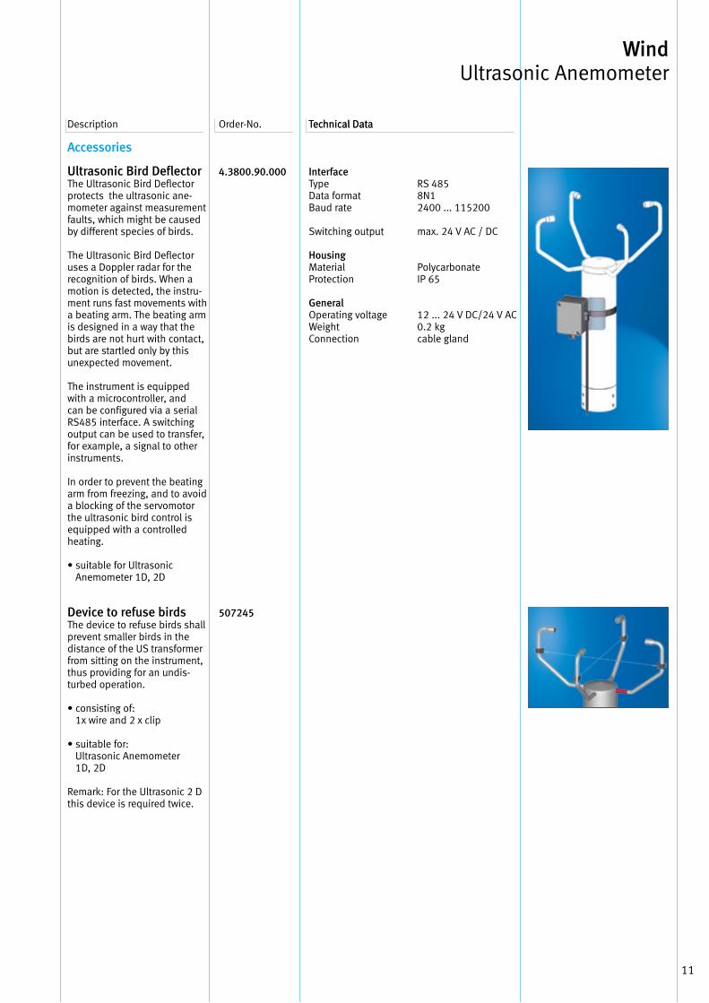
Ultrasonic Bird DeflectorThe Ultrasonic Bird Deflector protects the ultrasonic ane-mometer against measurement faults, which might be caused by different species of birds .
The Ultrasonic Bird Deflector uses a Doppler radar for the recognition of birds . When a motion is detected, the instru-ment runs fast movements with a beating arm . The beating arm is designed in a way that the birds are not hurt with contact, but are startled only by this unexpected movement .
The instrument is equipped with a microcontroller, and can be configured via a serial RS485 interface . A switching output can be used to transfer, for example, a signal to other instruments .
In order to prevent the beating arm from freezing, and to avoid a blocking of the servomotor the ultrasonic bird control is equipped with a controlled heating .
• suitable for Ultrasonic Anemometer 1D, 2D
Device to refuse birdsThe device to refuse birds shall prevent smaller birds in the distance of the US transformer from sitting on the instrument, thus providing for an undis-turbed operation .
• consisting of: 1x wire and 2 x clip
• suitable for: Ultrasonic Anemometer 1D, 2D
Remark: For the Ultrasonic 2 D this device is required twice .
4.3800.90.000
507245
InterfaceType Data formatBaud rate
Switching output
Housing Material Protection
General Operating voltage Weight Connection
RS 4858N12400 . . . 115200
max . 24 V AC / DC
PolycarbonateIP 65
12 . . . 24 V DC/24 V AC0 .2 kgcable gland
12
Description Order-No . Technical Data
Wind Ultrasonic Anemometer
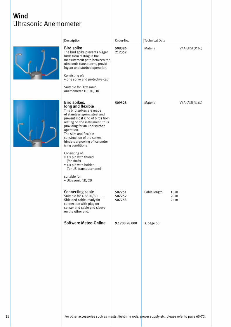
Bird spike The bird spike prevents bigger birds from resting in the measurement path between the ultrasonic transducers, provid-ing an undisturbed operation .
Consisting of:• one spike and protective cap
Suitable for UltrasonicAnemometer 1D, 2D, 3D
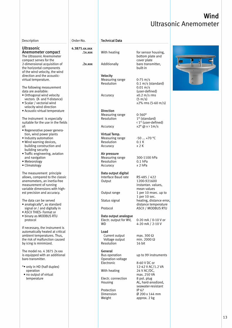
Bird spikes, long and flexibleThis bird spikes are made of stainless spring steel and prevent most kind of birds from resting on the instrument, thus providing for an undisturbed operation .The slim and flexible construction of the spikes hinders a growing of ice under icing conditions
Consisting of:• 1 x pin with thread
(for shaft)• 4 x pin with holder
(for US transducer arm)
suitable for:• Ultrasonic 1D, 2D
Connecting cable Suitable for 4 .3820/30 . . . . . . . . Shielded cable, ready for connection with plug on sensor and cable end sleeve on the other end .
Software Meteo-Online
508396212352
509528
507751507752507753
9.1700.98.000
Material
Material
Cable length 15 m 20 m 25 m
s . page 60
V4A (AISI 316L)
V4A (AISI 316L)
For other accessories such as masts, lightning rods, power supply etc . please refer to page 65-72 .
13
Wind Ultrasonic Anemometer
Description Order-No . Technical DataTechnical Data
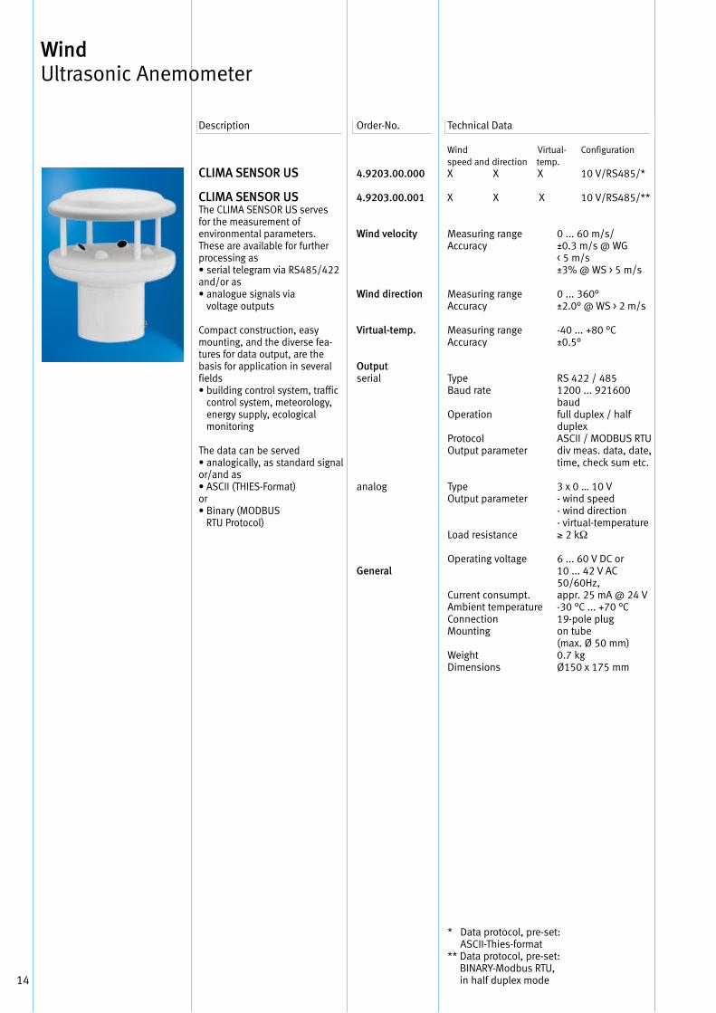
Ultrasonic Anemometer compact The Ultrasonic Anemometer compact serves for the 2-dimensional acquisition of the horizontal components of the wind velocity, the wind direction and the acoustic- virtual temperature .
The following measurement data are available:• Orthogonal wind velocity
vectors (X- and Y-distance)• Scalar / vectorial wind
velocity wind direction• Acoustic-virtual temperature
The instrument is especially suitable for the use in the fields of:• Regenerative power genera-
tion, wind power plants• Industry automation• Wind warning devices,
building construction and building security
• Traffic engineering, aviation and navigation
• Meteorology• Climatology
The measurement principle allows, compared to the classic anemometers, an inertia-free measurement of runningvariable dimensions with high-est precision and accuracy .
The data can be served• analogically*, as standard
signal or / and digitally in• ASCII THIES- Format or• binary as MODBUS RTU
protocol
If necessary, the instrument is automatically heated at critical ambient temperatures . Thus, the risk of malfunction caused by icing is minimized .
The model no . 4 3875 2x xxx is equipped with an additional baro transmitter .
* • only in HD (half duplex) operation • no output of virtual temperature
4.3875 .xx.xxx .1x.xxx .2x.xxx
With heating
Additionally
Velocity Measuring range Resolution
Accuracy
Direction Measuring range Resolution
Accuracy
Virtual Temp. Measuring range Resolution Accuracy
Air pressureMeasuring rangeResolutionAccuracy
Data output digitalInterface Baud rate Output
Output range
Status signal
Protocol
Data output analogueElectr . output for WV, WD
Load Current output Voltage output Resolution
GeneralBus operationOperation voltageElectronic
With heating
Electr . connectionHousing
Protection Dimension Weight
for sensor housing,bottom plate andcover platebaro transmitter, built-in
0-75 m/s0 .1 m/s (standard)0 .01 m/s(user-defined)±0 .2 m/s rms(5 m/s)±2% rms (5-60 m/s)
0-360°1° (standard)< 1° (user-defined)±2° @ v > 1m/s
-50 . . . +70 °C0 .1 K± 2 K
300-1100 hPa0 .1 hPa± 2 hPa
RS 485 / 4221200-921600instantan . values, mean values1 per 10 msec . up to1 per 10 sec . heating, distance error, distance temperatureASCII / MODBUS RTU
0-20 mA / 0-10 V or4-20 mA / 2-10 V
max . 300 Ωmin . 2000 Ω16 bit
up to 99 instruments
8-60 V DC or12-42 V AC/1 .2 VA24 V AC/DC, max . 250 VA8 pol . plugAL, hard-anodized,seawater-resistantIP 67Ø 200 x 144 mm approx . 2 kg
14
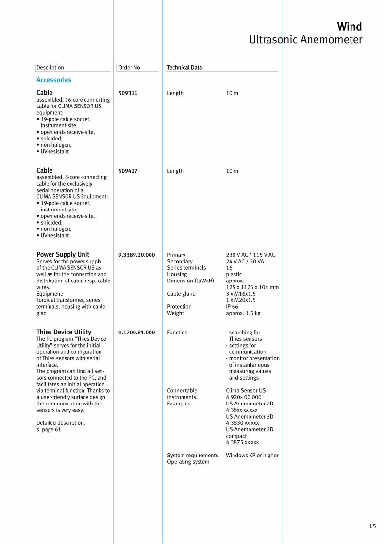
CLIMA SENSOR US
CLIMA SENSOR US The CLIMA SENSOR US serves for the measurement of environmental parameters .These are available for further processing as• serial telegram via RS485/422and/or as• analogue signals via
voltage outputs
Compact construction, easy mounting, and the diverse fea-tures for data output, are the basis for application in several fields• building control system, traffic
control system, meteorology, energy supply, ecological monitoring
The data can be served• analogically, as standard signal or/and as• ASCII (THIES-Format)or• Binary (MODBUS RTU Protocol)
4.9203.00.000
4.9203.00.001
Wind velocity
Wind direction
Virtual-temp.
Outputserial
analog
General
Measuring rangeAccuracy
Measuring rangeAccuracy
Measuring rangeAccuracy
TypeBaud rate
Operation
ProtocolOutput parameter
TypeOutput parameter
Load resistance
Operating voltage
Current consumpt . Ambient temperature Connection Mounting
WeightDimensions
0 . . . 60 m/s/±0 .3 m/s @ WG< 5 m/s±3% @ WS > 5 m/s
0 . . . 360°±2 .0° @ WS > 2 m/s
-40 . . . +80 °C±0 .5°
RS 422 / 4851200 . . . 921600baud full duplex / half duplexASCII / MODBUS RTU div meas . data, date, time, check sum etc .
3 x 0 … 10 V- wind speed- wind direction- virtual-temperature≥ 2 kΩ
6 . . . 60 V DC or10 . . . 42 V AC50/60Hz,appr . 25 mA @ 24 V-30 °C . . . +70 °C19-pole plugon tube(max . Ø 50 mm)0 .7 kgØ150 x 175 mm
Description Order-No . Technical Data
Wind Ultrasonic Anemometer
Wind Virtual- Configurationspeed and direction temp .X X X 10 V/RS485/*
X X X 10 V/RS485/**
* Data protocol, pre-set: ASCII-Thies-format
** Data protocol, pre-set: BINARY-Modbus RTU, in half duplex mode
15
Wind Ultrasonic Anemometer
Description Order-No . Technical DataTechnical Data
Accessories
Cable assembled, 16-core connecting cable for CLIMA SENSOR US equipment:• 19-pole cable socket,
instrument-site,• open ends receive-site,• shielded,• non-halogen,• UV-resistant
Cable assembled, 8-core connecting cable for the exclusively serial operation of a CLIMA SENSOR US Equipment:• 19-pole cable socket,
instrument-site,• open ends receive-site,• shielded,• non-halogen,• UV-resistant
Power Supply Unit Serves for the power supply of the CLIMA SENSOR US as well as for the connection and distribution of cable resp . cable wires .Equipment:Toroidal transformer, series terminals, housing with cable glad
Thies Device Utility The PC program “Thies Device Utility” serves for the initial operation and configuration of Thies sensors with serial interface .The program can find all sen-sors connected to the PC, and facilitates an initial operation via terminal function . Thanks to a user-friendly surface design the communication with the sensors is very easy .
Detailed description, s . page 61
509311
509427
9.3389.20.000
9.1700.81.000
Length
Length
Primary Secondary Series terminals HousingDimension (LxWxH)
Cable gland
ProtectionWeight
Function
Connectable instruments,Examples
System requirements Operating system
10 m
10 m
230 V AC / 115 V AC24 V AC / 30 VA16plastic approx . 125 x 1125 x 104 mm3 x M16x1 .51 x M20x1 .5IP 66approx . 1 .5 kg
- searching for Thies sensors
- settings for communication
- monitor presentation of instantaneous measuring values and settings
Clima Sensor US4 920x 00 000US-Anemometer 2D4 38xx xx xxxUS-Anemometer 3D4 3830 xx xxxUS-Anemometer 2Dcompact4 3875 xx xxx
Windows XP or higher

16
Your Notice
17
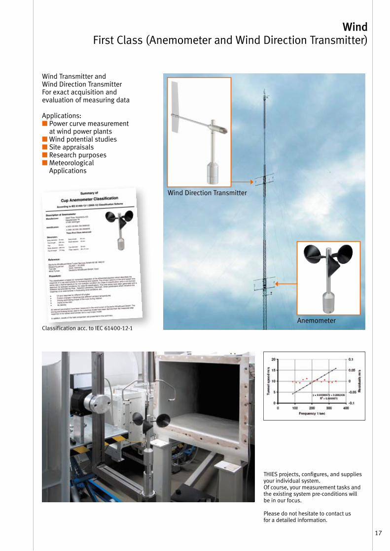
THIES projects, configures, and suppliesyour individual system .Of course, your measurement tasks and the existing system pre-conditions will be in our focus .
Please do not hesitate to contact us for a detailed information .
Classification acc . to IEC 61400-12-1
Wind Transmitter andWind Direction TransmitterFor exact acquisition andevaluation of measuring data Applications:■ Power curve measurement
at wind power plants■ Wind potential studies■ Site appraisals■ Research purposes■ Meteorological
Applications
Wind First Class (Anemometer and Wind Direction Transmitter)
Einsatz-Beispiele
Wind Direction Transmitter
Anemometer
18
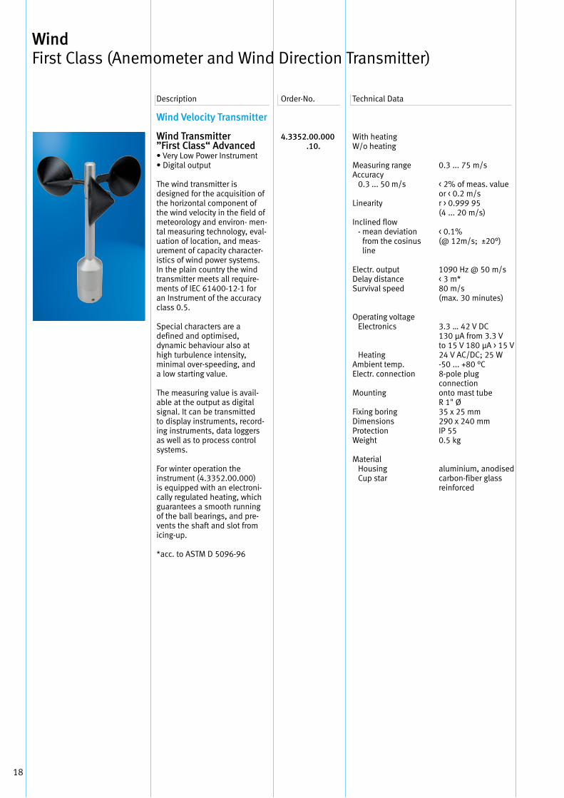
Wind Velocity Transmitter
Wind Transmitter”First Class“ Advanced• Very Low Power Instrument• Digital output
The wind transmitter is designed for the acquisition of the horizontal component of the wind velocity in the field of meteorology and environ- men-tal measuring technology, eval-uation of location, and meas-urement of capacity character-istics of wind power systems . In the plain country the wind transmitter meets all require-ments of IEC 61400-12-1 for an Instrument of the accuracy class 0 .5 .
Special characters are a defined and optimised, dynamic behaviour also at high turbulence intensity, minimal over-speeding, and a low starting value .
The measuring value is avail-able at the output as digital signal . It can be transmitted to display instruments, record-ing instruments, data loggers as well as to process control systems .
For winter operation the instrument (4 .3352 .00 .000) is equipped with an electroni-cally regulated heating, which guarantees a smooth runningof the ball bearings, and pre-vents the shaft and slot from icing-up .
*acc . to ASTM D 5096-96
4.3352.00.000 .10.
With heatingW/o heating
Measuring rangeAccuracy 0 .3 . . . 50 m/s
Linearity
Inclined flow - mean deviation
from the cosinus line
Electr . output Delay distance Survival speed
Operating voltage Electronics
Heating Ambient temp . Electr . connection
Mounting
Fixing boring Dimensions Protection Weight
Material Housing Cup star
0 .3 . . . 75 m/s
< 2% of meas . value or < 0 .2 m/sr > 0 .999 95 (4 . . . 20 m/s)
< 0 .1%(@ 12m/s; ±20°)
1090 Hz @ 50 m/s< 3 m*80 m/s(max . 30 minutes)
3 .3 … 42 V DC130 μA from 3 .3 Vto 15 V 180 μA > 15 V24 V AC/DC; 25 W-50 . . . +80 °C8-pole plug connectiononto mast tube R 1" Ø 35 x 25 mm290 x 240 mmIP 550 .5 kg
aluminium, anodised carbon-fiber glass reinforced
Description Order-No . Technical Data
Wind First Class (Anemometer and Wind Direction Transmitter)
19
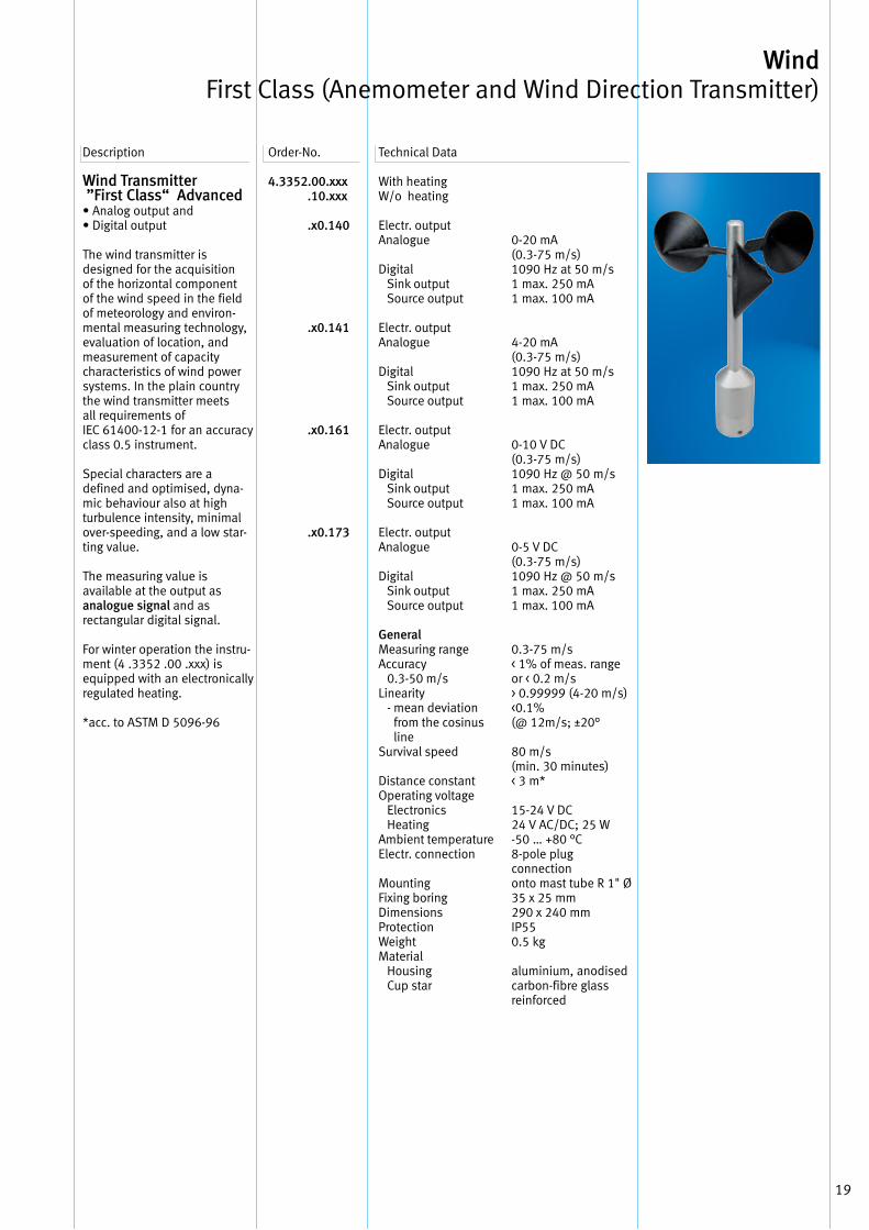
Wind Transmitter ”First Class“ Advanced• Analog output and • Digital output The wind transmitter is designed for the acquisition of the horizontal component of the wind speed in the field of meteorology and environ-mental measuring technology, evaluation of location, and measurement of capacity characteristics of wind power systems . In the plain country the wind transmitter meets all requirements of IEC 61400-12-1 for an accuracy class 0 .5 instrument .
Special characters are a defined and optimised, dyna-mic behaviour also at high turbulence intensity, minimal over-speeding, and a low star-ting value .
The measuring value is available at the output as analogue signal and as rectangular digital signal .
For winter operation the instru-ment (4 .3352 .00 .xxx) is equipped with an electronically regulated heating .
*acc . to ASTM D 5096-96
4.3352.00.xxx .10.xxx
.x0.140
.x0.141
.x0.161
.x0.173
Description Order-No . Technical Data
With heating W/o heating
Electr . outputAnalogue
Digital Sink output Source output
Electr . outputAnalogue
Digital Sink output Source output
Electr . outputAnalogue
Digital Sink output Source output
Electr . outputAnalogue
Digital Sink output Source output
GeneralMeasuring range Accuracy 0 .3-50 m/sLinearity - mean deviation
from the cosinus line
Survival speed
Distance constantOperating voltage Electronics HeatingAmbient temperatureElectr . connection
Mounting Fixing boring DimensionsProtectionWeight Material Housing Cup star
0-20 mA(0 .3-75 m/s)1090 Hz at 50 m/s1 max . 250 mA1 max . 100 mA
4-20 mA(0 .3-75 m/s)1090 Hz at 50 m/s1 max . 250 mA1 max . 100 mA
0-10 V DC(0 .3-75 m/s)1090 Hz @ 50 m/s1 max . 250 mA1 max . 100 mA
0-5 V DC(0 .3-75 m/s)1090 Hz @ 50 m/s1 max . 250 mA1 max . 100 mA
0 .3-75 m/s< 1% of meas . rangeor < 0 .2 m/s> 0 .99999 (4-20 m/s)<0 .1%(@ 12m/s; ±20°
80 m/s(min . 30 minutes)< 3 m*
15-24 V DC24 V AC/DC; 25 W-50 … +80 °C8-pole plug connectiononto mast tube R 1" Ø 35 x 25 mm290 x 240 mmIP550 .5 kg
aluminium, anodised carbon-fibre glass reinforced
Wind First Class (Anemometer and Wind Direction Transmitter)
20
Description Order-No . Technical Data
Wind Direction Transmitter
Wind DirectionTransmitter ”First Class“ • Low Power Instrument
With digital output (Thies serial-synchronous)
The wind transmitter is desi-gned for the acquisition of the horizontal component of the wind direction in the field of meteorology and environmental measuring technology, evalua-tion of location, and measure-ment of capacity characteristics of wind power systems .
Special characters are a defined and optimised, dynamic behaviour as well as:• High measurement accuracy
and resolution• High damping with small
distance constant• Low starting value• Low power consumption• Simple mounting
The measuring value is available at the output as digital signal . The output signal can be trans-mitted to display instruments, recording instruments, data loggers as well as to process control systems .
For winter operation the instrument (4 .3150 .00 .xxx) is equipped with an electronically regulated heating .
* acc . to ASTM D 5096-96** acc . to VDI 3786 page 2
Wind Direction Transmitter ”First Class“ • Digital output RS 485
The wind transmitter is desi-gned for the acquisition of the horizontal component of the wind direction in the field of meteorology and environmental measuring technology, evalua -tion of location, and measure-ment of capacity characteristics of wind power systems . Special characters are a defined and optimised, dynamic behaviour as well as:• High measurement accuracy
and resolution• High damping with small
distance constant• Low starting value• Low power consumption• Simple mounting
4.3151.00.00x .10.00x
.x0.000
.x0.001
4.3151.00.400 .10.400
With heatingW/o heating
Measuring rangeAccuracy
Electr . outputResolution
Electr . outputResolution
Operating voltage Electronics Current consumption Heating Ambient temp . Starting value
Distance constantDamping ratioElectr . connection
Mounting
Fixing boring Dimensions Protection Weight Material
With heatingW/o heating
Measuring range Accuracy Resolution
Electr . output Interface Baud rateOutput telegram
Operating voltage Electronic Current consumption
HeatingAmbient temperature Starting value
0-360°1° (0 .5°)
8 bit serial-synchron2 .5°
10 bit serial-synchron0 .35°
3 .3-42 V DC1 .4 mA . standby24 V AC/DC; 25 W-50 . . . +80 °C< 0 .5 m/s at 10°*< 0 .2 m/s at 90°**< 1 .8 m*D > 0 .3*8-pole plug connectiononto mast tube R 1" Ø 35 x 25 mmH: 410, D: 450 mmIP 550 .7 kgaluminium, anodised
0-360°1°0 .1°
RS 4851200-57600 baudxxx .xx for ex . 075 .1
3 .3-42 V DCapprox . 1 mA @ 3 .3Vapprox . 1 .5 mA @ 5V24 V AC/DC; 25 W-50 . . . +80 °C< 0 .5 m/s at 10°*< 0 .2 m/s at 90°**
Wind First Class (Anemometer and Wind Direction Transmitter)
Continuation on page 21
21
Description Order-No . Technical DataTechnical Data
Continuation of page 20
The measuring value is available at the output as digital signal . The output signal can be trans-mitted to display instru ments, recording instruments, data loggers as well as to process control systems .
Characteristic:The WD transmitter can acquire the WS signals of 4 .3352 .x .000, and add the parameter wind speed to its serial data telegram
* acc . to ASTM D 5096-96** acc . to VDI 3786 page 2
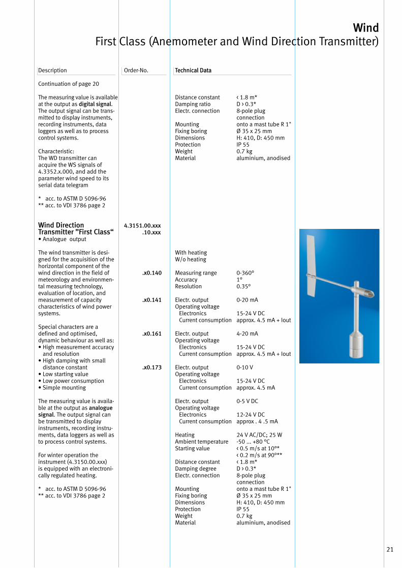
Wind Direction Transmitter ”First Class“ • Analogue output
The wind transmitter is desi-gned for the acquisition of the horizontal component of the wind direction in the field of meteorology and environmen-tal measuring technology, evaluation of location, and measurement of capacity characteristics of wind power systems .
Special characters are a defined and optimised, dynamic behaviour as well as:• High measurement accuracy
and resolution• High damping with small
distance constant• Low starting value• Low power consumption• Simple mounting
The measuring value is availa-ble at the output as analogue signal . The output signal can be transmitted to display instruments, recording instru-ments, data loggers as well as to process control systems .
For winter operation the instrument (4 .3150 .00 .xxx) is equipped with an electroni-cally regulated heating .
* acc . to ASTM D 5096-96** acc . to VDI 3786 page 2
4.3151.00.xxx .10.xxx
.x0.140
.x0.141
.x0.161 .x0.173
Distance constantDamping ratioElectr . connection
Mounting Fixing boring Dimensions Protection Weight Material
With heatingW/o heating
Measuring rangeAccuracyResolution
Electr . outputOperating voltage Electronics Current consumption
Electr . outputOperating voltage Electronics Current consumption
Electr . outputOperating voltage Electronics Current consumption
Electr . outputOperating voltage Electronics Current consumption
HeatingAmbient temperatureStarting value
Distance constantDamping degreeElectr . connection
MountingFixing boringDimensionsProtectionWeightMaterial
< 1 .8 m* D > 0 .3*8-pole plug connectiononto a mast tube R 1" Ø 35 x 25 mmH: 410, D: 450 mmIP 550 .7 kgaluminium, anodised
0-360° 1° 0 .35°
0-20 mA
15-24 V DC approx . 4 .5 mA + Iout
4-20 mA
15-24 V DCapprox . 4 .5 mA + Iout
0-10 V
15-24 V DCapprox . 4 .5 mA
0-5 V DC
12-24 V DCapprox . 4 .5 mA
24 V AC/DC; 25 W -50 . . . +80 °C < 0 .5 m/s at 10°*< 0 .2 m/s at 90°**< 1 .8 m* D > 0 .3*8-pole plug connectiononto a mast tube R 1"Ø 35 x 25 mm H: 410, D: 450 mmIP 55 0 .7 kg aluminium, anodised
Wind First Class (Anemometer and Wind Direction Transmitter)
22
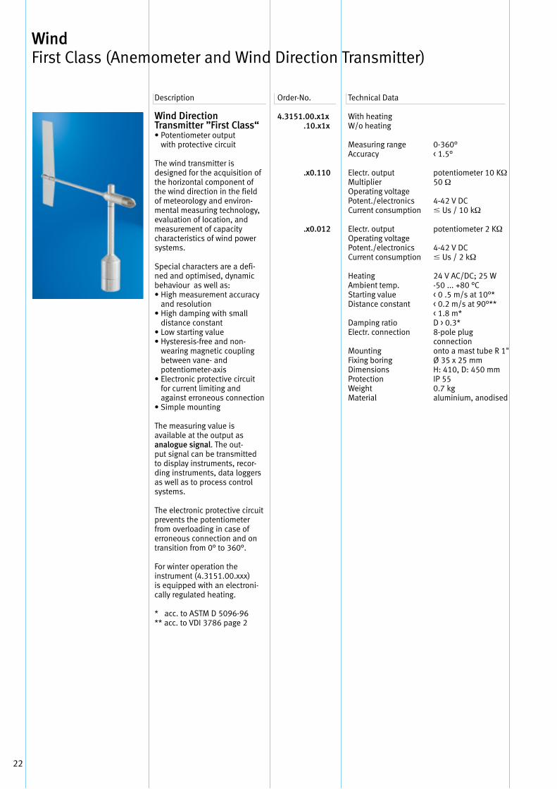
Wind Direction Transmitter ”First Class“• Potentiometer output
with protective circuit
The wind transmitter is designed for the acquisition of the horizontal component of the wind direction in the field of meteorology and environ-mental measuring technology, evaluation of location, and measurement of capacity characteristics of wind power systems .
Special characters are a defi-ned and optimised, dynamic behaviour as well as:• High measurement accuracy
and resolution• High damping with small
distance constant• Low starting value• Hysteresis-free and non-
wearing magnetic coupling between vane- and potentiometer-axis
• Electronic protective circuit for current limiting and against erroneous connection
• Simple mounting
The measuring value is available at the output as analogue signal . The out-put signal can be transmitted to display instruments, recor-ding instruments, data loggers as well as to process control systems .
The electronic protective circuit prevents the potentiometer from overloading in case of erroneous connection and on transition from 0° to 360° .
For winter operation the instrument (4 .3151 .00 .xxx) is equipped with an electroni-cally regulated heating .
* acc . to ASTM D 5096-96** acc . to VDI 3786 page 2
4.3151.00.x1x .10.x1x
.x0.110
.x0.012
With heatingW/o heating
Measuring rangeAccuracy
Electr . outputMultiplier Operating voltagePotent ./electronicsCurrent consumption
Electr . outputOperating voltagePotent ./electronicsCurrent consumption
HeatingAmbient temp .Starting valueDistance constant
Damping ratioElectr . connection
MountingFixing boringDimensionsProtectionWeightMaterial
0-360° < 1 .5°
potentiometer 10 KΩ 50 Ω
4-42 V DC Us / 10 kΩ
potentiometer 2 KΩ
4-42 V DC Us / 2 kΩ
24 V AC/DC; 25 W -50 . . . +80 °C < 0 .5 m/s at 10°*< 0 .2 m/s at 90°**< 1 .8 m*D > 0 .3*8-pole plug connectiononto a mast tube R 1"Ø 35 x 25 mm H: 410, D: 450 mmIP 55 0 .7 kg aluminium, anodised
Description Order-No . Technical Data
Wind First Class (Anemometer and Wind Direction Transmitter)
23
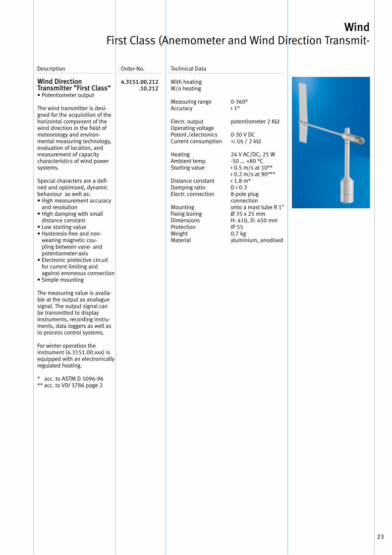
Wind Direction Transmitter ”First Class“• Potentiometer output
The wind transmitter is desi-gned for the acquisition of the horizontal component of the wind direction in the field of meteorology and environ-mental measuring technology, evaluation of location, and measurement of capacity characteristics of wind power systems .
Special characters are a defi-ned and optimised, dynamic behaviour as well as:• High measurement accuracy
and resolution• High damping with small
distance constant• Low starting value• Hysteresis-free and non-
wearing magnetic cou-pling between vane- and potentiometer-axis
• Electronic protective circuit for current limiting and against erroneous connection
• Simple mounting
The measuring value is availa-ble at the output as analogue signal . The output signal can be transmitted to display instruments, recording instru-ments, data loggers as well as to process control systems .
For winter operation the instrument (4 .3151 .00 .xxx) is equipped with an electronically regulated heating .
* acc . to ASTM D 5096-96** acc . to VDI 3786 page 2
4.3151.00.212 .10.212
Description Order-No . Technical Data
With heatingW/o heating
Measuring rangeAccuracy
Electr . outputOperating voltagePotent ./electronicsCurrent consumption
HeatingAmbient temp .Starting value
Distance constantDamping ratioElectr . connection
MountingFixing boringDimensionsProtectionWeightMaterial
0-360° < 1°
potentiometer 2 KΩ
0-30 V DC Us / 2 kΩ
24 V AC/DC; 25 W -50 . . . +80 °C < 0 .5 m/s at 10°*< 0 .2 m/s at 90°**< 1 .8 m*D > 0 .38-pole plug connectiononto a mast tube R 1"Ø 35 x 25 mm H: 410, D: 450 mmIP 55 0 .7 kg aluminium, anodised
Wind First Class (Anemometer and Wind Direction Transmit-

24
Your Notice
25
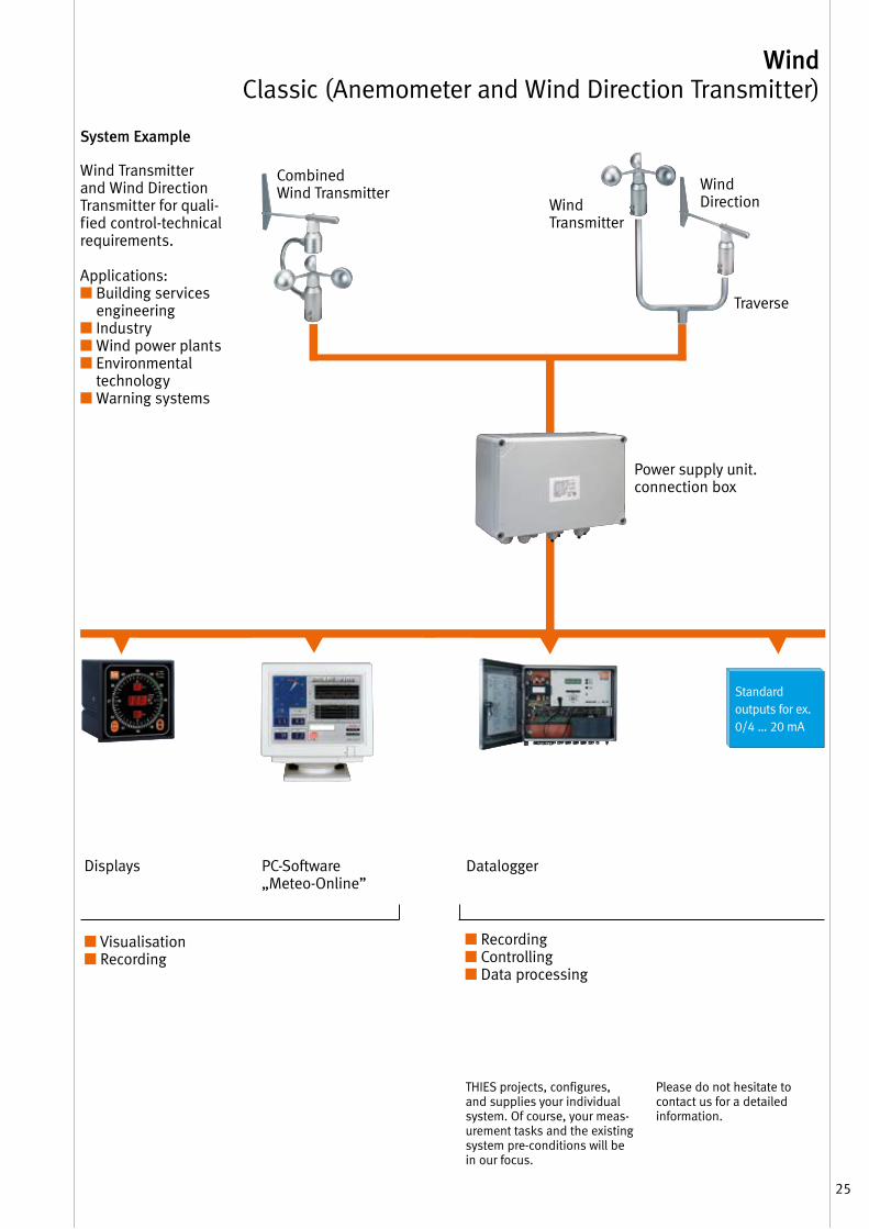
Wind Classic (Anemometer and Wind Direction Transmitter)
Power supply unit . connection box
Wind Transmitter
Traverse
■ Visualisation ■ Recording
■ Recording■ Controlling ■ Data processing
PC-Software „Meteo-Online”
Displays Datalogger
Standard outputs for ex . 0/4 … 20 mA
THIES projects, configures, and supplies your individual system . Of course, your meas-urement tasks and the existing system pre-conditions will be in our focus .
Please do not hesitate to contact us for a detailed information .
Wind Direction
Combined Wind Transmitter
System Example
Wind Transmitter and Wind Direction Transmitter for quali-fied control-technical requirements .
Applications: ■ Building services
engineering■ Industry■ Wind power plants■ Environmental
technology■ Warning systems
26
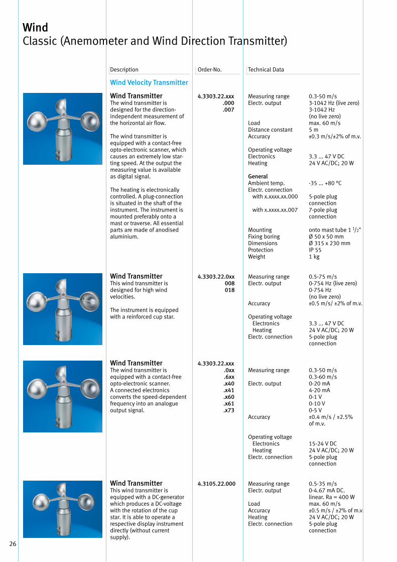
Wind Velocity Transmitter
Wind Transmitter The wind transmitter is designed for the direction-independent measurement of the horizontal air flow .
The wind transmitter is equipped with a contact-free opto-electronic scanner, which causes an extremely low star-ting speed . At the output the measuring value is available as digital signal .
The heating is electronically controlled . A plug-connection is situated in the shaft of the instrument . The instrument is mounted preferably onto a mast or traverse . All essential parts are made of anodised aluminium .
Wind Transmitter This wind transmitter is designed for high wind velocities .
The instrument is equippedwith a reinforced cup star .
Wind Transmitter The wind transmitter is equipped with a contact-free opto-electronic scanner . A connected electronics converts the speed-dependent frequency into an analogue output signal .
Wind Transmitter This wind transmitter is equipped with a DC-generator which produces a DC-voltage with the rotation of the cup star . It is able to operate a respective display instrument directly (without current supply) .
4.3303.22.xxx .000 .007
4.3303.22.0xx 008 018
4.3303.22.xxx .0xx .6xx .x40 .x41 .x60 .x61 .x73
4.3105.22.000
Measuring range Electr . output
Load Distance constant Accuracy
Operating voltage Electronics Heating
General Ambient temp . Electr . connection with x .xxxx .xx .000
with x .xxxx .xx .007
Mounting Fixing boring Dimensions Protection Weight
Measuring range Electr . output
Accuracy
Operating voltage Electronics Heating Electr . connection
Measuring range
Electr . output
Accuracy
Operating voltage Electronics HeatingElectr . connection
Measuring range Electr . output
Load Accuracy Heating Electr . connection
0 .3-50 m/s3-1042 Hz (live zero)3-1042 Hz (no live zero)max . 60 m/s5 m±0 .3 m/s/±2% of m .v .
3 .3 . . . 47 V DC 24 V AC/DC; 20 W
-35 . . . +80 °C
5-pole plug connection7-pole plug connection
onto mast tube 1 1/2"Ø 50 x 50 mmØ 315 x 230 mmIP 551 kg
0 .5-75 m/s0-754 Hz (live zero)0-754 Hz (no live zero)±0 .5 m/s/ ±2% of m .v .
3 .3 . . . 47 V DC 24 V AC/DC; 20 W5-pole plug connection
0 .3-50 m/s0 .3-60 m/s0-20 mA4-20 mA0-1 V0-10 V0-5 V±0 .4 m/s / ±2 .5% of m .v .
15-24 V DC24 V AC/DC; 20 W5-pole plug connection
0 .5-35 m/s0-4 .67 mA DC . linear . Ra = 400 Wmax . 60 m/s±0 .5 m/s / ±2% of m .v .24 V AC/DC; 20 W5-pole plug connection
Description Order-No . Technical Data
Wind Classic (Anemometer and Wind Direction Transmitter)
27
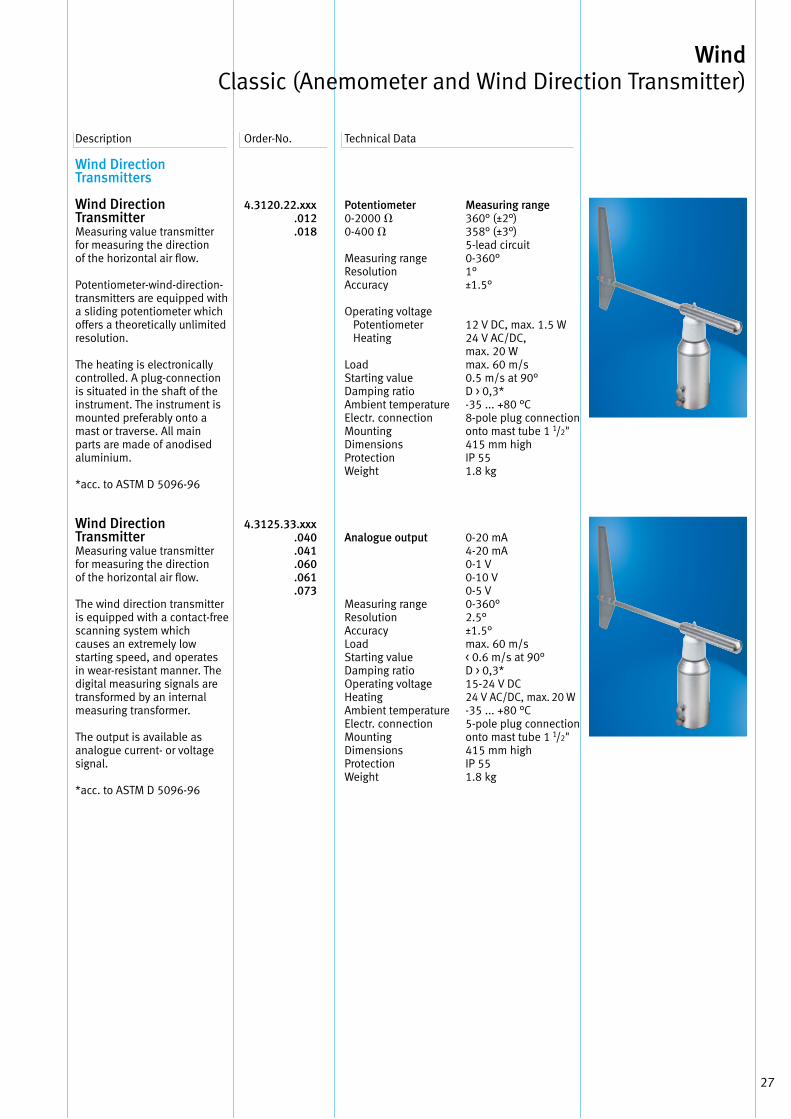
Wind Direction Transmitters
Wind Direction TransmitterMeasuring value transmitter for measuring the direction of the horizontal air flow .
Potentiometer-wind-direction-transmitters are equipped with a sliding potentiometer which offers a theoretically unlimited resolution .
The heating is electronically controlled . A plug-connection is situated in the shaft of the instrument . The instrument is mounted preferably onto a mast or traverse . All main parts are made of anodised aluminium .
*acc . to ASTM D 5096-96
Wind Direction TransmitterMeasuring value transmitter for measuring the direction of the horizontal air flow .
The wind direction transmitter is equipped with a contact-freescanning system whichcauses an extremely low starting speed, and operates in wear-resistant manner . The digital measuring signals are transformed by an internal measuring transformer .
The output is available as analogue current- or voltage signal . *acc . to ASTM D 5096-96
4.3120.22.xxx .012 .018
4.3125.33.xxx .040 .041 .060 .061 .073
Description Order-No . Technical Data
Potentiometer0-2000 V0-400 V
Measuring range Resolution Accuracy
Operating voltage Potentiometer Heating
Load Starting value Damping ratio Ambient temperature Electr . connection Mounting Dimensions Protection Weight
Analogue output
Measuring range Resolution Accuracy Load Starting value Damping ratio Operating voltage Heating Ambient temperature Electr . connection Mounting Dimensions ProtectionWeight
Measuring range360° (±2°)358° (±3°) 5-lead circuit0-360°1°±1 .5°
12 V DC, max . 1 .5 W24 V AC/DC, max . 20 Wmax . 60 m/s0 .5 m/s at 90°D > 0,3*-35 . . . +80 °C8-pole plug connectiononto mast tube 1 1/2"415 mm highIP 551 .8 kg
0-20 mA4-20 mA0-1 V0-10 V0-5 V0-360°2 .5°±1 .5°max . 60 m/s< 0 .6 m/s at 90°D > 0,3*15-24 V DC24 V AC/DC, max . 20 W-35 . . . +80 °C5-pole plug connectiononto mast tube 1 1/2"415 mm highIP 551 .8 kg
Wind Classic (Anemometer and Wind Direction Transmitter)
28
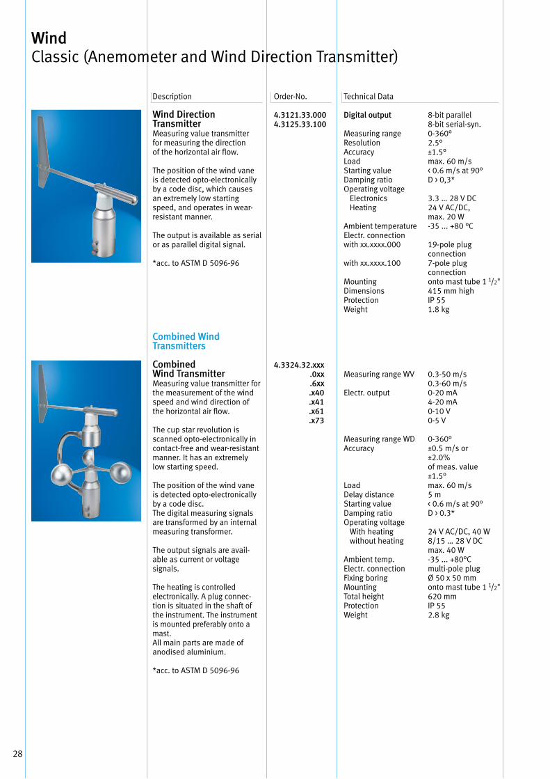
Wind Direction TransmitterMeasuring value transmitter for measuring the direction of the horizontal air flow .
The position of the wind vane is detected opto-electronically by a code disc, which causes an extremely low starting speed, and operates in wear-resistant manner .
The output is available as serial or as parallel digital signal . *acc . to ASTM D 5096-96
Combined Wind Transmitters
Combined Wind Transmitter Measuring value transmitter for the measurement of the wind speed and wind direction of the horizontal air flow .
The cup star revolution is scanned opto-electronically in contact-free and wear-resistant manner . It has an extremely low starting speed .
The position of the wind vane is detected opto-electronically by a code disc . The digital measuring signals are transformed by an internal measuring transformer .
The output signals are avail-able as current or voltage signals .
The heating is controlled electro nically . A plug connec-tion is situated in the shaft of the instrument . The instrument is mounted preferably onto a mast . All main parts are made of anodised aluminium .
*acc . to ASTM D 5096-96
4.3121.33.0004.3125.33.100
4.3324.32.xxx .0xx .6xx .x40 .x41 .x61 .x73
Digital output
Measuring range Resolution Accuracy Load Starting value Damping ratio Operating voltage Electronics Heating
Ambient temperature Electr . connection with xx .xxxx .000
with xx .xxxx .100
Mounting Dimensions ProtectionWeight
Measuring range WV
Electr . output
Measuring range WD Accuracy
Load Delay distance Starting valueDamping ratio Operating voltage With heating without heating
Ambient temp . Electr . connection Fixing boring Mounting Total height Protection Weight
8-bit parallel8-bit serial-syn .0-360°2 .5°±1 .5°max . 60 m/s< 0 .6 m/s at 90°D > 0,3*
3 .3 … 28 V DC24 V AC/DC, max . 20 W-35 . . . +80 °C
19-pole plug connection7-pole plug connectiononto mast tube 1 1/2"415 mm highIP 551 .8 kg
0 .3-50 m/s0 .3-60 m/s0-20 mA4-20 mA0-10 V0-5 V
0-360°±0 .5 m/s or±2 .0% of meas . value ±1 .5°max . 60 m/s5 m< 0 .6 m/s at 90°D > 0 .3*
24 V AC/DC, 40 W8/15 … 28 V DCmax . 40 W-35 . . . +80°Cmulti-pole plugØ 50 x 50 mmonto mast tube 1 1/2"620 mmIP 552 .8 kg
Description Order-No . Technical Data
Wind Classic (Anemometer and Wind Direction Transmitter)
29
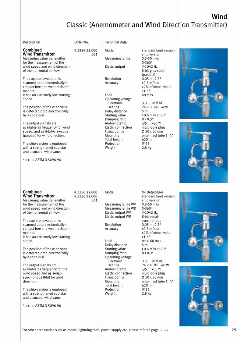
Combined Wind Transmitter Measuring value transmitter for the measurement of the wind speed and wind direction of the horizontal air flow .
The cup star revolution is scanned opto-electronically in contact-free and wear-resistant manner . It has an extremely low starting speed .
The position of the wind vane is detected opto-electronically by a code disc .
The output signals are available as frequency for wind speed, and as 8-bit-Gray-code (parallel) for wind direction .
The ship-version is equipped with a strengthened cup star and a smaller wind vane .
*acc . to ASTM D 5096-96
Combined Wind Transmitter Measuring value transmitter for the measurement of the wind speed and wind direction of the horizontal air flow .
The cup star revolution is scanned opto-electronically in contact-free and wear-resistant manner . It has an extremely low starting speed .
The position of the wind vane is detected opto-electronically by a code disc .
The output signals are available as frequency for the wind speed and as serial-synchronous 8-bit for wind direction .
The ship-version is equipped with a strengthened cup star and a smaller wind vane .
*acc . to ASTM D 5096-96
4.3324.32.000 .001
4.3336.22.0004.3336.32.000 .001
Description Order-No . Technical Data
Model
Measuring range
Electr . output
ResolutionAccuracy
LoadOperating voltage Electronik HeatingDelay distance Starting valueDamping ratio Ambient temp . Electr . connection Fixing boring Mounting Total height ProtectionWeight
Model
Measuring range WV Measuring range WD Electr . output WV Electr . output WD
Resolution Accuracy
Load Delay distance Starting value Damping ratioOperating voltage Electronic HeatingAmbient temp . Electr . connection Fixing boring Mounting Total height Protection Weight
standard land version ship version 0 .3-50 m/s0-360°3-1042 Hz8-bit-gray-code (parallel)0 .05 m; 2 .5°±0 .3 m/s or±2% of meas . value±1 .5°60 m/s
3 .3 … 28 V DC 24 V DC/AC, 40W5 m< 0 .6 m/s at 90°D > 0 .3*-35 . . . +80 °Cmulti-pole plugØ 50 x 50 mmonto mast tube 1 1/2"620 mmIP 552 .8 kg
for Dataloggerstandard land version ship version 0 .3-50 m/s0-360°3-1042 Hz8-bit serial- synchronous0 .05 m; 2 .5°±0 .3 m/s or±2% of meas . value±1 .5°max . 60 m/s5 m< 0 .6 m/s at 90°D > 0 .3*
3 .3 … 28 V DC24 V AC/DC, 40 W-35 . . . +80 °Cmulti-pole plugØ 50 x 50 mmonto mast tube 1 1/2"620 mmIP 552 .8 kg
For other accessories such as masts, lightning rods, power supply etc . please refer to page 65-72 .
Wind Classic (Anemometer and Wind Direction Transmitter)

30
Your Notice
31
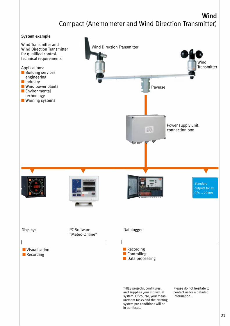
Wind Compact (Anemometer and Wind Direction Transmitter)
Wind Transmitter andWind Direction Transmitter for qualified control- technical requirements
Applications:■ Building services
engineering■ Industry■ Wind power plants■ Environmental
technology■ Warning systems
System example
Power supply unit . connection box
Wind Transmitter
Traverse
Wind Direction Transmitter
Displays
■ Visualisation ■ Recording
■ Recording■ Controlling ■ Data processing
PC-Software ”Meteo-Online”
Datalogger
Standard outputs for ex . 0/4 … 20 mA
THIES projects, configures, and supplies your individual system . Of course, your meas-urement tasks and the existing system pre-conditions will be in our focus .
Please do not hesitate to contact us for a detailed information .
32
Wind Velocity Transmitters
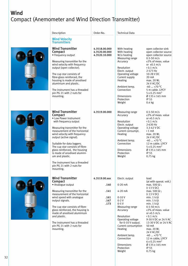
Wind Transmitter Compact• Frequency output
Measuring transmitter for the wind velocity with frequency output (open collector) .
The cup star consists of fibre-glass reinforced, the housing is made of anodised aluminium and plastic .
The instrument has a threaded pin PG 21 with 2 nuts for mounting .
Wind Transmitter Compact • Low Power Instrument with frequency output
Measuring transmitter for the measurement of the horizontal wind velocity with frequency output (active signal) .
Suitable for data loggers . The cup star consists of fibre-glass reinforced, the housing is made of anodised alumini-um and plastic .
The instrument has a threaded pin PG 21 with 2 nuts for mounting .
Wind Transmitter Compact• Analogue output
Measuring transmitter for the measurement of the horizontal wind speed with analogue output signals .
The cup star consists of fibre-glass reinforced, the housing is made of anodised aluminium and plastic .
The instrument has a threaded pin PG 21 with 2 nuts for mounting .
4.3518.00.0004.3520.00.0004.3520.10.000
4.3519.00.000
4.3519.00.xxx
.140
.141
.161 .167 .173
With heating With heating W/o heating Measuring range Accuracy
Resolution Electr . output Operating voltage Current supply Heating
Ambient temp . Connection
Dimensions Protection Weight
Measuring range Accuracy
Resolution Electr . output Operating voltage Current consumpt . Heating
Ambient temp . Connection
DimensionsProtection Weight
Electr . output
0-20 mA
4-20 mA
0-10 V 0-2 V 0-5 V Measuring range Accuracy
Resolution Operating voltage for 0-10 V output . Current consumptionHeating
Ambient temp . Connection
Dimensions ProtectionWeight
open collector sinkopen collector sourceopen collector source0 .5-50 m/s±3% of meas . valueor ±0 .5 m/s< 0 .1 m/s2-573 Hz10-28 V DC20 mAmax . 20 W; 24 V AC/DC-40 . . . +70 °C5 m cable . LiYCY 5 x 0 .25 mm2 Ø 135 x 165 mmIP 550 .4 kg
0 .5-50 m/s±3% of meas . valueor ±0 .5 m/s< 0 .1 m/s2-630 Hz 3 .3-42 V DC< 1 mAmax . 20 W; 24 V AC/DC-40 . . . +70 °C12 m cable . LiYCY 5 x 0 .25 mm2
Ø 135 x 165 mmIP 550 .75 kg
load (at with operat . volt .)max . 500 Ω ; (> 13 V DC)max . 500 Ω ; (> 13 V DC)min . 1 k Ωmin . 1 k Ωmin . 1 k Ω0 .5-50 m/s±3% of meas . valueor ±0 .5 m/s< 0 .1 m/s9-30 V DC or 24 V AC13-30 V DC or 24 V AC 50 mAmax . 20 W; 24 V AC/DC-40 . . . +70 °C12 m cable, LiYCY 6 x 0 .25 mm2
Ø 135 x 165 mmIP 550 .75 kg
Description Order-No . Technical Data
Wind Compact (Anemometer and Wind Direction Transmitter)
33
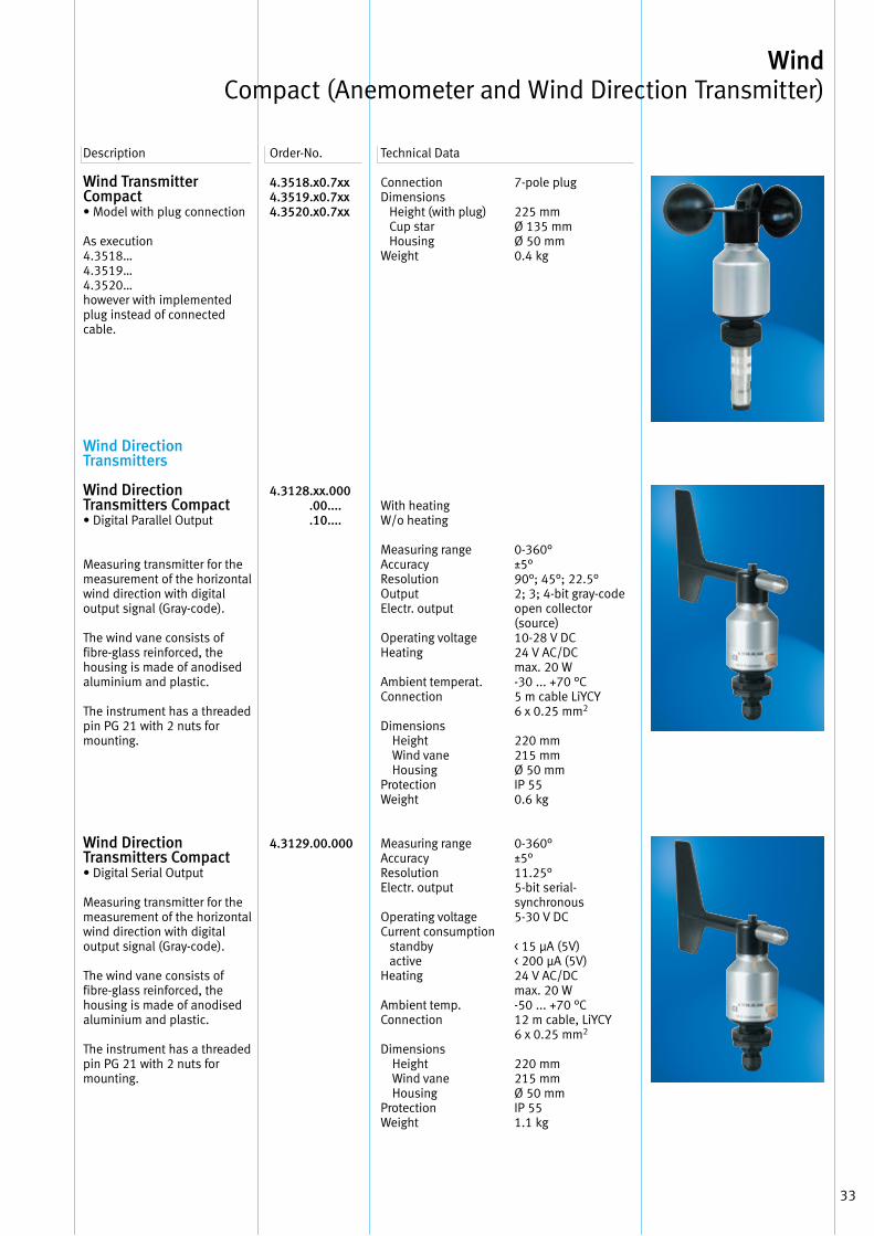
Wind Transmitter Compact• Model with plug connection
As execution 4 .3518…4 .3519…4 .3520…however with implemented plug instead of connected cable .
Wind Direction Transmitters
Wind Direction Transmitters Compact • Digital Parallel Output
Measuring transmitter for the measurement of the horizontal wind direction with digital output signal (Gray-code) .
The wind vane consists of fibre-glass reinforced, the housing is made of anodised aluminium and plastic .
The instrument has a threaded pin PG 21 with 2 nuts for mounting .
Wind Direction Transmitters Compact • Digital Serial Output
Measuring transmitter for the measurement of the horizontal wind direction with digital output signal (Gray-code) .
The wind vane consists of fibre-glass reinforced, the housing is made of anodised aluminium and plastic .
The instrument has a threaded pin PG 21 with 2 nuts for mounting .
4.3518.x0.7xx 4.3519.x0.7xx4.3520.x0.7xx
4.3128.xx.000 .00.... .10....
4.3129.00.000
Description Order-No . Technical Data
ConnectionDimensions Height (with plug) Cup star HousingWeight
With heatingW/o heating
Measuring range Accuracy Resolution OutputElectr . output
Operating voltageHeating
Ambient temperat .Connection
Dimensions Height Wind vane HousingProtectionWeight
Measuring range Accuracy Resolution Electr . output
Operating voltage Current consumption standby activeHeating
Ambient temp . Connection
Dimensions Height Wind vane HousingProtectionWeight
7-pole plug
225 mmØ 135 mmØ 50 mm0 .4 kg
0-360°±5°90°; 45°; 22 .5°2; 3; 4-bit gray-codeopen collector (source)10-28 V DC24 V AC/DCmax . 20 W -30 . . . +70 °C 5 m cable LiYCY 6 x 0 .25 mm2
220 mm215 mmØ 50 mmIP 55 0 .6 kg
0-360°±5°11 .25°5-bit serial- synchronous 5-30 V DC
< 15 μA (5V)< 200 μA (5V)24 V AC/DCmax . 20 W -50 . . . +70 °C 12 m cable, LiYCY 6 x 0 .25 mm2
220 mm215 mmØ 50 mmIP 55 1 .1 kg
Wind Compact (Anemometer and Wind Direction Transmitter)
34
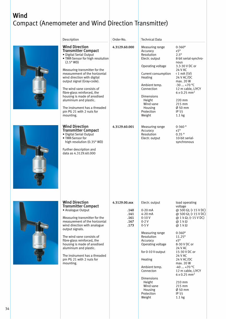
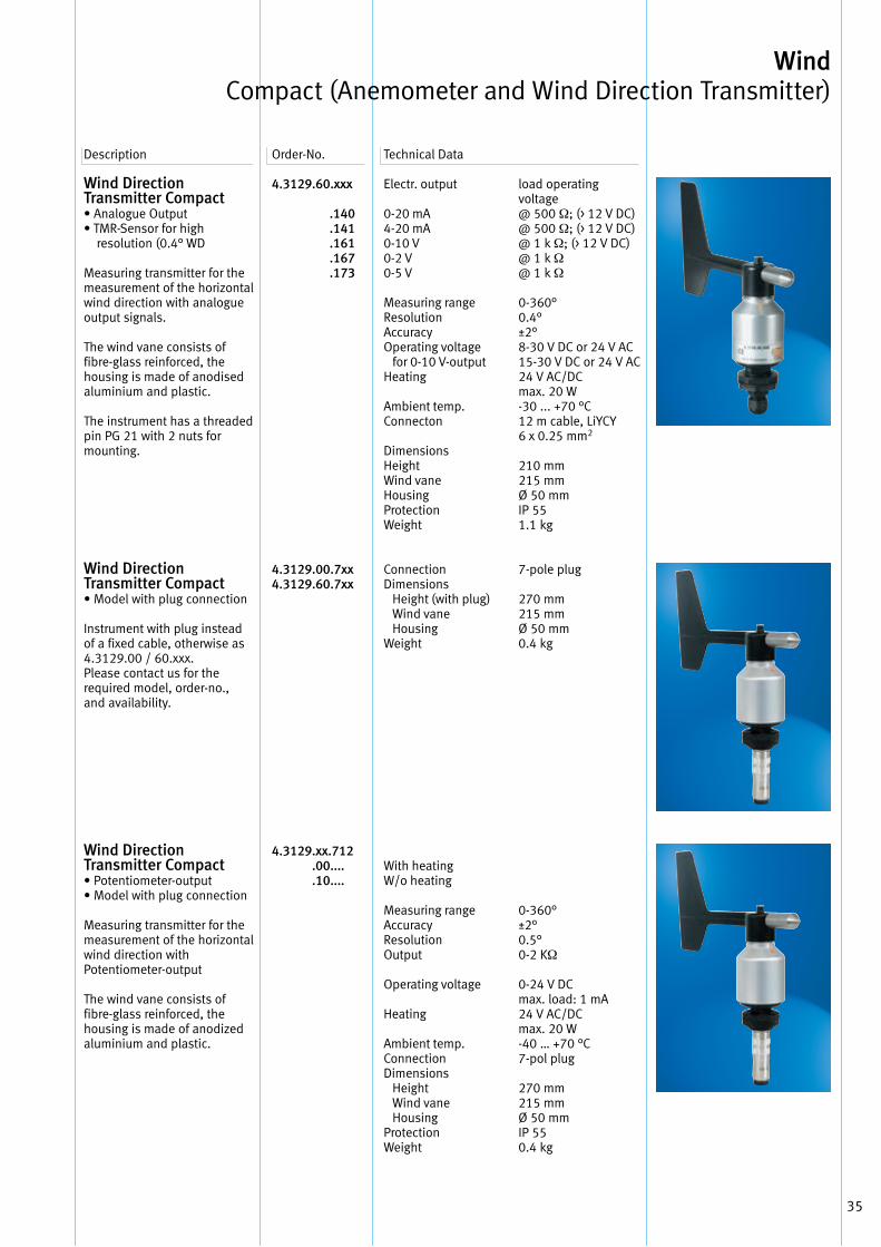
Wind Direction Transmitter Compact • Digital Serial Output• TMR-Sensor for high resolution
(2 .5° WD)
Measuring transmitter for the measurement of the horizontal wind direction with digital output signal (Gray-code) .
The wind vane consists of fibre-glass reinforced, the housing is made of anodised aluminium and plastic .
The instrument has a threaded pin PG 21 with 2 nuts for mounting .
Wind Direction Transmitter Compact • Digital Serial Output• TMR-Sensor for
high resolution (0 .35° WD)
Further description and data as 4 .3129 .60 .000
Wind Direction Transmitter Compact • Analogue Output
Measuring transmitter for the measurement of the horizontal wind direction with analogue output signals .
The wind vane consists of fibre-glass reinforced, the housing is made of anodised aluminium and plastic .
The instrument has a threaded pin PG 21 with 2 nuts for mounting .
4.3129.60.000
4.3129.60.001
4.3129.00.xxx .140 .141 .161 .167 .173
Measuring range Accuracy Resolution Electr . output
Operating voltage
Current consumption Heating
Ambient temp . Connection
Dimensions Height Wind vane HousingProtectionWeight
Measuring range Accuracy Resolution Electr . output
Electr . output
0-20 mA 4-20 mA 0-10 V 0-2 V 0-5 V
Measuring range Resolution Accuracy Operating voltage
for 0-10 V-output
Heating
Ambient temp . Connecton
Dimensions Height Wind vane HousingProtectionWeight
0-360°±5°2 .5°8-bit serial-synchro-nous3 .3-30 V DC or24 V AC< 1 mA (5V)24 V AC/DCmax . 20 W -30 . . . +70 °C 12 m cable, LiYCY 6 x 0 .25 mm2
220 mm215 mmØ 50 mmIP 55 1 .1 kg
0-360 °±1°0 .35 °10-bit serial- synchronous
load operating voltage @ 500 Ω; (> 15 V DC) @ 500 Ω; (> 15 V DC) @ 1 k Ω; (> 15 V DC)@ 1 k Ω @ 1 k Ω
0-360° 11 .25° ±5° 8-30 V DC or24 V AC 15-30 V DC or24 V AC24 V AC/DCmax . 20 W -40 . . . +70 °C 12 m cable, LiYCY 6 x 0 .25 mm2
210 mm215 mmØ 50 mmIP 55 1 .1 kg
Description Order-No . Technical Data
Wind Compact (Anemometer and Wind Direction Transmitter)
35
Wind Direction Transmitter Compact • Analogue Output• TMR-Sensor for high
resolution (0 .4° WD
Measuring transmitter for the measurement of the horizontal wind direction with analogue output signals .
The wind vane consists of fibre-glass reinforced, the housing is made of anodised aluminium and plastic .
The instrument has a threaded pin PG 21 with 2 nuts for mounting .
Wind DirectionTransmitter Compact• Model with plug connection
Instrument with plug instead of a fixed cable, otherwise as 4 .3129 .00 / 60 .xxx .Please contact us for the required model, order-no ., and availability .
Wind Direction Transmitter Compact• Potentiometer-output• Model with plug connection
Measuring transmitter for the measurement of the horizontal wind direction with Potentiometer-output
The wind vane consists of fibre-glass reinforced, the housing is made of anodized aluminium and plastic .
4.3129.60.xxx .140 .141 .161 .167 .173
4.3129.00.7xx 4.3129.60.7xx
4.3129 .xx.712 .00.... .10....
Description Order-No . Technical Data
Electr . output
0-20 mA 4-20 mA0-10 V0-2 V0-5 V
Measuring range Resolution Accuracy Operating voltage for 0-10 V-output Heating
Ambient temp . Connecton
Dimensions HeightWind vaneHousingProtectionWeight
ConnectionDimensions Height (with plug) Wind vane HousingWeight
With heating W/o heating
Measuring rangeAccuracyResolutionOutput
Operating voltage
Heating
Ambient temp . Connection Dimensions Height Wind vane HousingProtectionWeight
load operating voltage@ 500 Ω; (> 12 V DC) @ 500 Ω; (> 12 V DC) @ 1 k Ω; (> 12 V DC)@ 1 k Ω @ 1 k Ω
0-360° 0 .4° ±2° 8-30 V DC or 24 V AC 15-30 V DC or 24 V AC24 V AC/DCmax . 20 W -30 . . . +70 °C 12 m cable, LiYCY 6 x 0 .25 mm2
210 mm215 mmØ 50 mmIP 55 1 .1 kg
7-pole plug
270 mm215 mmØ 50 mm0 .4 kg
0-360°±2°0 .5°0-2 KΩ
0-24 V DC max . load: 1 mA24 V AC/DCmax . 20 W-40 … +70 °C7-pol plug
270 mm215 mmØ 50 mmIP 550 .4 kg
Wind Compact (Anemometer and Wind Direction Transmitter)

36
Your Notice
37
Wind Cold Climate (Anemometer, Wind Transmitters
and Wind Direction Transmitters)
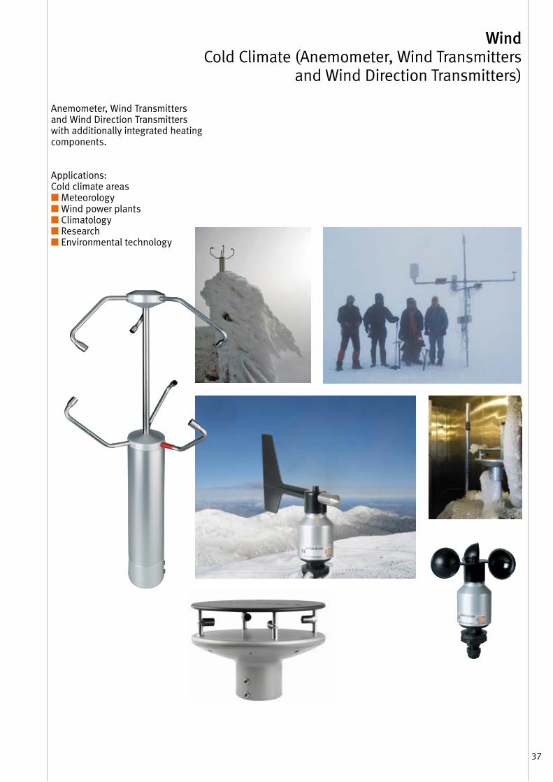
Anemometer, Wind Transmitters and Wind Direction Transmitters with additionally integrated heating components .
Applications: Cold climate areas ■ Meteorology■ Wind power plants■ Climatology■ Research■ Environmental technology
38
Description Order-No . Technical Data
Wind Cold Climate (Anemometer, Wind Transmitters and Wind Direction Transmitters)
Anemometer
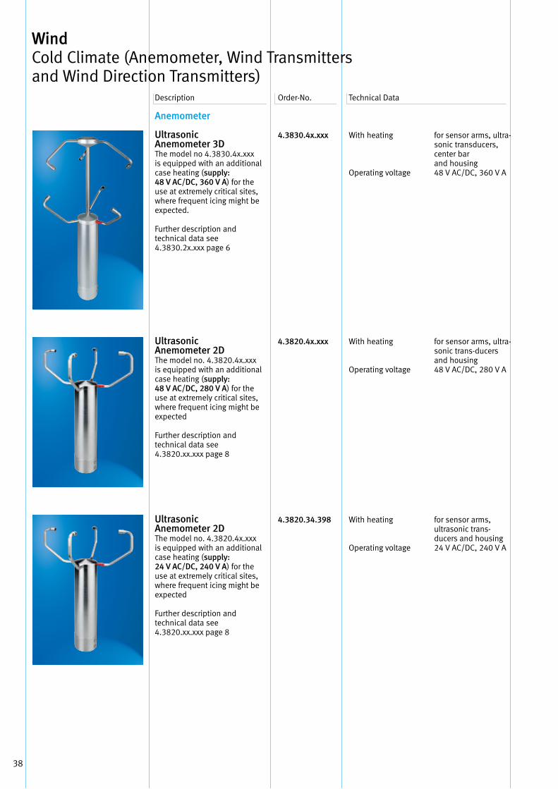
UltrasonicAnemometer 3DThe model no 4 .3830 .4x .xxx is equipped with an additional case heating (supply: 48 V AC/DC, 360 V A) for the use at extremely critical sites, where frequent icing might be expected .
Further description and technical data see4 .3830 .2x .xxx page 6
UltrasonicAnemometer 2DThe model no . 4 .3820 .4x .xxx is equipped with an additional case heating (supply: 48 V AC/DC, 280 V A) for the use at extremely critical sites, where frequent icing might be expected
Further description and technical data see4 .3820 .xx .xxx page 8
UltrasonicAnemometer 2DThe model no . 4 .3820 .4x .xxx is equipped with an additional case heating (supply: 24 V AC/DC, 240 V A) for the use at extremely critical sites, where frequent icing might be expected
Further description and technical data see4 .3820 .xx .xxx page 8
4.3830.4x.xxx
4.3820.4x.xxx
4.3820.34.398
With heating
Operating voltage
With heating
Operating voltage
With heating
Operating voltage
for sensor arms, ultra-sonic trans ducers, center barand housing48 V AC/DC, 360 V A
for sensor arms, ultra-sonic trans-ducers and housing48 V AC/DC, 280 V A
for sensor arms, ultrasonic trans -ducers and housing24 V AC/DC, 240 V A
39
Wind Cold Climate (Anemometer, Wind Transmitters
and Wind Direction Transmitters)Description Order-No . Technical Data
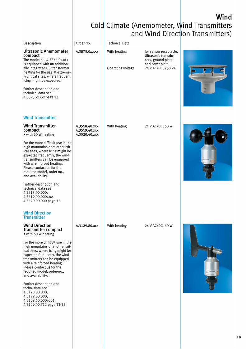
Ultrasonic Anemometer compactThe model no . 4 .3875 .0x .xxx is equipped with an addition-ally integrated US transformer heating for the use at extreme-ly critical sites, where frequent icing might be expected .
Further description and technical data see4 .3875 .xx .xxx page 13
Wind Transmitter
Wind Transmitter compact• with 60 W heating
For the more difficult use in the high mountains or at other crit-ical sites, where icing might be expected frequently, the wind transmitters can be equipped with a reinforced heating .Please contact us for the required model, order-no ., and availability .
Further description and technical data see4 .3518 .00 .000,4 .3519 .00 .000/xxx,4 .3520 .00 .000 page 32
Wind Direction Transmitter
Wind Direction Transmitter compact• with 60 W heating
For the more difficult use in the high mountains or at other crit-ical sites, where icing might be expected frequently, the wind transmitters can be equipped with a reinforced heating .Please contact us for the required model, order-no ., and availability .
Further description and techn . data see4 .3128 .00 .000,4 .3129 .00 .000,4 .3129 .60 .000/001,4 .3129 .00 .712 page 33-35
4.3875.0x.xxx
4.3518.40.xxx4.3519.40.xxx4.3520.40.xxx
4.3129.80.xxx
With heating
Operating voltage
With heating
With heating
for sensor receptacle, Ultrasonic transdu-cers, ground plate and cover plate24 V AC/DC, 250 VA
24 V AC/DC, 60 W
24 V AC/DC, 60 W

40
Your Notice
41
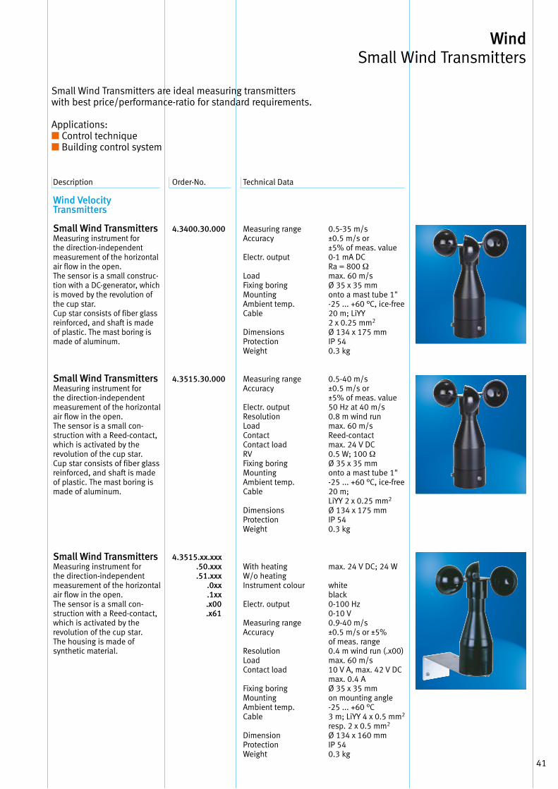
Wind Small Wind Transmitters
Wind VelocityTransmitters
Small Wind TransmittersMeasuring instrument for the direction-independent measurement of the horizontal air flow in the open . The sensor is a small construc-tion with a DC-generator, which is moved by the revolution of the cup star . Cup star consists of fiber glass reinforced, and shaft is made of plastic . The mast boring is made of aluminum .
Small Wind TransmittersMeasuring instrument for the direction-independent measurement of the horizontal air flow in the open . The sensor is a small con-struc tion with a Reed-contact, which is activated by the revolution of the cup star . Cup star consists of fiber glass reinforced, and shaft is made of plastic . The mast boring is made of aluminum .
Small Wind TransmittersMeasuring instrument for the direction-independent measurement of the horizontal air flow in the open . The sensor is a small con-struction with a Reed-contact, which is activated by the revolution of the cup star . The housing is made of synthetic material .
4.3400.30.000
4.3515.30.000
4.3515.xx.xxx .50.xxx .51.xxx .0xx .1xx .x00 .x61
Description Order-No . Technical Data
Measuring range Accuracy
Electr . output
Load Fixing boring Mounting Ambient temp . Cable
Dimensions Protection Weight
Measuring range Accuracy
Electr . output Resolution Load Contact Contact load RV Fixing boring Mounting Ambient temp . Cable
Dimensions Protection Weight
With heating W/o heating Instrument colour
Electr . output
Measuring range Accuracy
Resolution Load Contact load
Fixing boring Mounting Ambient temp . Cable
Dimension Protection Weight
0 .5-35 m/s±0 .5 m/s or ±5% of meas . value0-1 mA DCRa = 800 Ωmax . 60 m/sØ 35 x 35 mmonto a mast tube 1" -25 . . . +60 °C, ice-free 20 m; LiYY 2 x 0 .25 mm2
Ø 134 x 175 mmIP 540 .3 kg
0 .5-40 m/s±0 .5 m/s or ±5% of meas . value50 Hz at 40 m/s0 .8 m wind runmax . 60 m/sReed-contactmax . 24 V DC0 .5 W; 100 ΩØ 35 x 35 mmonto a mast tube 1" -25 . . . +60 °C, ice-free 20 m; LiYY 2 x 0 .25 mm2
Ø 134 x 175 mmIP 540 .3 kg
max . 24 V DC; 24 W
whiteblack0-100 Hz0-10 V0 .9-40 m/s±0 .5 m/s or ±5% of meas . range0 .4 m wind run ( .x00)max . 60 m/s10 V A, max . 42 V DCmax . 0 .4 AØ 35 x 35 mmon mounting angle -25 . . . +60 °C3 m; LiYY 4 x 0 .5 mm2
resp . 2 x 0 .5 mm2
Ø 134 x 160 mmIP 540 .3 kg
Small Wind Transmitters are ideal measuring transmitters with best price/performance-ratio for standard requirements .
Applications:■ Control technique■ Building control system
42
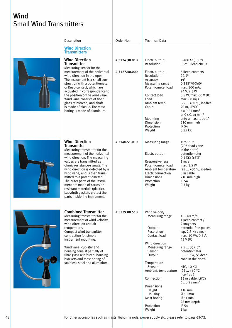
Wind Direction Transmitters
Wind Direction Transmitter Measuring sensor for the measurement of the horizontal wind direction in the open . The instrument is a small con-struction with a potentiometer or Reed-contact, which are activated in correspondence to the position of the wind vane . Wind vane consists of fiber glass reinforced, and shaft is made of plastic . The mast boring is made of aluminum .
Wind Direction Transmitter Measuring transmitter for the measurement of the horizontal wind direction . The measuring values are transmitted as ohmic resistance-signals . The wind direction is detected by a wind vane, and is then trans-mitted to a potentiometer . The outer parts of the instru-ment are made of corrosion-resistant materials (plastic) . Labyrinth gaskets protect the parts inside the instrument .
Combined Transmitter Measuring transmitter for themeasurement of wind velocity,wind direction and air temperature .Compact wind transmittercontruction for simple instrument mounting .
Wind vane, cup star and housing consist partially of fibre glass reinforced, housing brackets and mast boring of stainless steel and aluminium .
4.3124.30.018
4.3127.40.000
4.3140.51.010
4.3329.00.510
Electr . output Resolution
Electr . output Resolution AccuracyMeasuring range Potentiometer load
Contact load Load Ambient temp . Cable
Mounting Dimension Protection Weight
Measuring range
Electr . output
Responsiveness Potentiometer load Ambient temperature Electr . connection Dimensions Protection Weight
Wind velocity Measuring range
Output Resolution Contact load
Wind direction Measuring range Sensor Output
Temperature Sensor Ambient . temperature
Connection
Dimensions Height Housing Mast boring
Protection Weight
0-400 Ω (358°)0 .5°, 5-lead circuit
8 Reed contacts 22 .5°±4°0-358°/0-360°max . 100 mA, 24 V, 2 .5 W0 .5 W, max . 60 V DCmax . 60 m/s-25 . . . +60 °C, ice-free 20 m, LiYCY 5 x 0 .25 mm2
or 9 x 0 .14 mm2
onto a mast tube 1" 210 mm highIP 540 .55 kg
10°-350° (20° dead-zone in the north)potentiometer 0-1 KΩ (±3%)1 m/smax . 1 .5 W-25 . . . +60 °C, ice-free 3 m cable210 mm highIP 540 .3 kg
1 . . . 40 m/s1 Reed contact / 2 magnetspotential-free pulsestyp . 2 .3 Hz / ms-1
max . 10 VA, 0 .5 A,42 V DC
2 .5 . . . 357 .5°potentiometer0 . . . 1 KΩ, 5° dead-zone in the North
NTC, 10 KΩ-25 . . . +60 °C (ice-free )15 m cable, LiYCY 6 x 0 .25 mm2
418 mmØ 50 mmØ 31 mm 26 mm depth IP 54 1 kg
Description Order-No . Technical Data
Wind Small Wind Transmitters
For other accessories such as masts, lightning rods, power supply etc . please refer to page 65-72 .
43
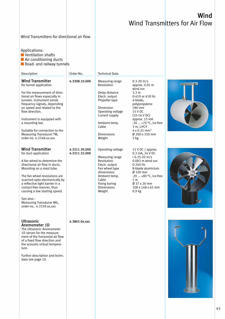
Wind Wind Transmitters for Air Flow
Description Order-No . Technical Data
Wind Transmitter for tunnel application
For the measurement of direc-tional air flows especially in tunnels . Instrument sends frequency signals, depending on speed and related to the flow direction .
Instrument is equipped with a mounting bar .
Suitable for connection to the Measuring Transducer TW, order-no . 4 .3348 .xx .xxx
Wind Transmitter for duct application
A fan wheel to determine the directional air flow in ducts . Mounting on a mast tube .
The fan wheel revolutions are scanned opto-electronically by a reflective light barrier in a contact-free manner, thus causing a low starting speed .
See also : Measuring Transducer WG, order-no . . 4 .3339 .xx .xxx
Ultrasonic Anemometer 1DThe Ultrasonic Anemometer1D serves for the measure- ment of the horizontal air flow of a fixed flow direction and the acoustic-virtual tempera-ture .
Further description and techn . data see page 10 .
4.3308.10.000
4.3311.30.0004.3311.32.000
4.3865.0x.xxx
Measuring range Resolution
Delay distance Electr . output Propeller type
Dimension Operating voltage Current supply
Ambient temp . Cable
Dimensions Weight
Operating voltage
Measuring range Resolution Electr . output Fan wheel type dimensions Ambient temp . Cable Fixing boring Dimensions Weight
0 .3-20 m/sapprox . 0 .05 m wind run3 .3 m0-410 or 418 Hz4-blade, polypropylene 180 mm15 V DC (10-16 V DC)approx . 15 mA-20 . . . +70 °C, ice-free 3 m, LiYCY 4 x 0 .25 mm2
Ø 200 x 350 mm5 kg
15 V DC / approx . 0 .3 mA, 24 V DC< 0 .25-20 m/s0 .083 m wind run0-240 Hz8-blade aluminium Ø 100 mm-20 . . . +80 °C, ice-free 1 m Ø 37 x 20 mm108 x 148 x 65 mm0 .9 kg
Wind Transmitters for directional air flow
Applications:■ Ventilation shafts■ Air conditioning ducts■ Road- and railway tunnels

44
Your Notice
45
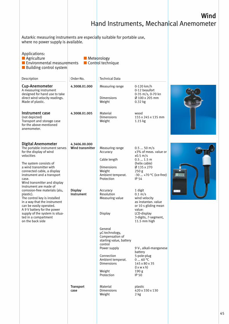
Description Order-No . Technical Data
Cup-Anemometer A measuring instrument designed for hand use to take direct wind velocity readings . Made of plastic .
Instrument case (not depicted) Transport and storage case for the above-mentioned anemometer .
Digital AnemometerThe portable instrument servesfor the display of wind velocities
The system consists ofa wind transmitter with connected cable, a displayinstrument and a transportcase .Wind transmitter and displayinstrument are made of corrosion-free materials (alu,plastic) .The control key is installedin a way that the instrument can be easily operated .A 9 V battery for the powersupply of the system is situa-ted in a compartment on the back side
4.3008.01.000
4.3008.01.005
4.3406.00.000 Wind transmitter
Display Instrument
Transportcase
Measuring range
Dimensions Weight
Material Dimensions Weight
Measuring rangeAccuracy
Cable length
DimensionsWeightAmbient temperat .Protection
AccuracyResolutionMeasuring value
Display
General μC-technology,Compensation ofstarting value, battery control Power supply
ConnectionAmbient temperat .Dimensions
Weight Protection
MaterialDimensionsWeight
0-120 km/h0-12 beaufort 0-35 m/s, 0-70 knØ 100 x 205 mm0 .32 kg
wood 155 x 245 x 135 mm1 .15 kg
0 .5 . . . 50 m/s±3% of meas . value or ±0 .5 m/s0 .5 … 1 .5 m (helix cable)Ø 135 x 270250 g-30 … +70 °C (ice-free)IP 54
1 digit0 .1 m/swind velocityas instantan . valueor 10 s gliding mean value:LCD-display3-digits, 7-segment,11 .5 mm high
9 V-, alkali-manganese battery5-pole-plug0 . . . 60 °C145 x 80 x 35 (l x w x h)190 gIP 50
plastic 420 x 330 x 130 2 kg
Autarkic measuring instruments are especially suitable for portable use, where no power supply is available .
Wind Hand Instruments, Mechanical Anemometer
Applications:■ Agriculture ■ Environmental measurements■ Building control system
■ Meteorology■ Control technique
46
Telescope - suitable for Digital Anemometer 4 .3406 .00 .000
Serves as extended handhold of the wind transmitterfor carrying out measurementsat places which are difficult to reach .
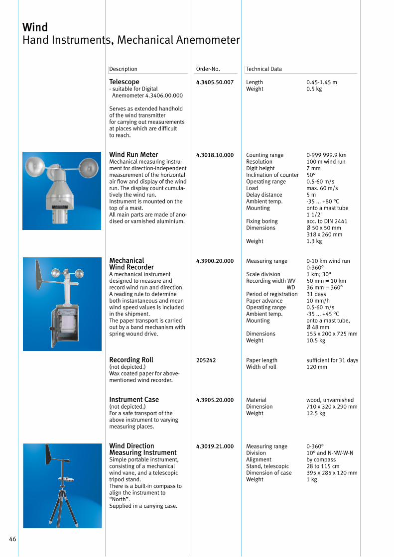
Wind Run Meter Mechanical measuring instru-ment for direction-independent measurement of the horizontal air flow and display of the wind run . The display count cumula-tively the wind run . Instrument is mounted on the top of a mast . All main parts are made of ano-dised or varnished aluminium .
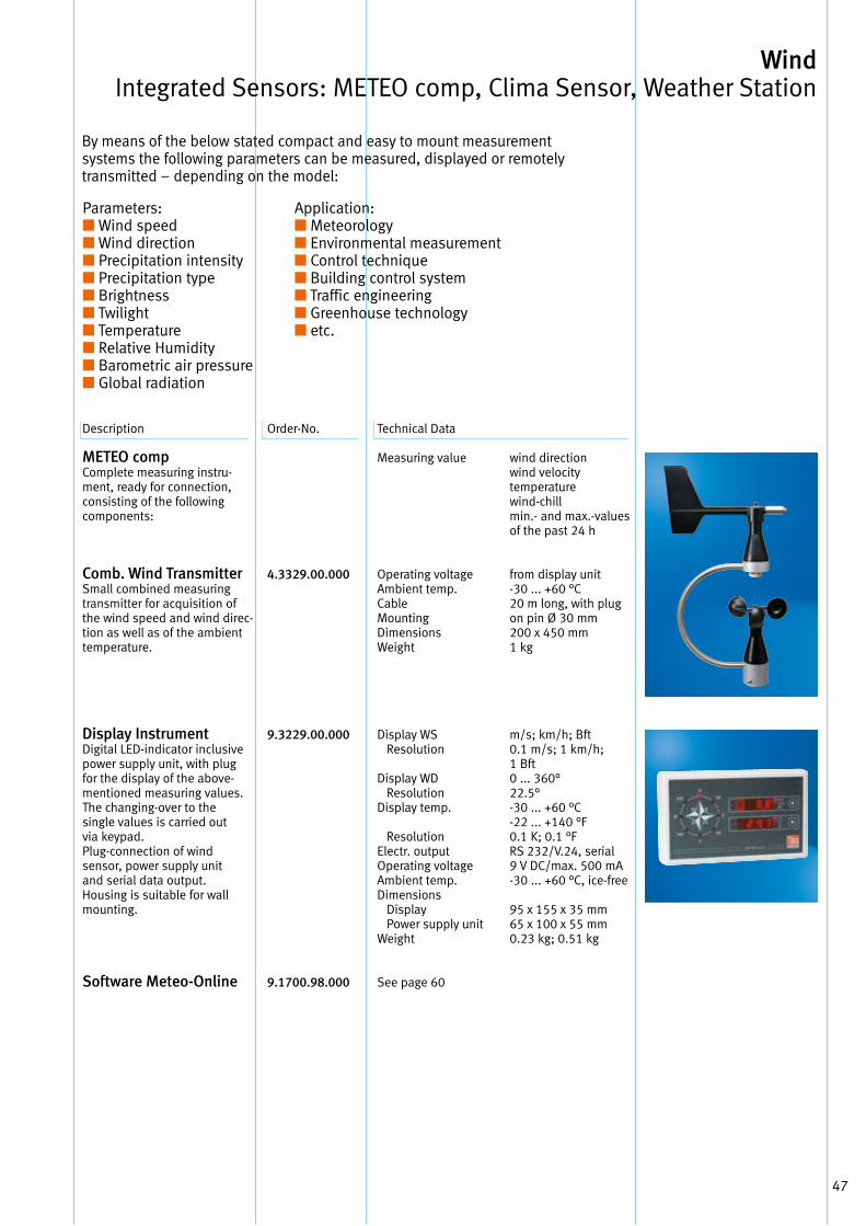
Mechanical Wind Recorder A mechanical instrument designed to measure and record wind run and direction . A reading rule to determine both instantaneous and mean wind speed values is included in the shipment . The paper transport is carried out by a band mechanism with spring wound drive .
Recording Roll (not depicted .) Wax coated paper for above-mentioned wind recorder .
Instrument Case (not depicted .) For a safe transport of the above instrument to varying measuring places .
Wind Direction Measuring Instrument Simple portable instrument, consisting of a mechanical wind vane, and a telescopic tripod stand . There is a built-in compass to align the instrument to “North” . Supplied in a carrying case .
4.3405.50.007
4.3018.10.000
4.3900.20.000
205242
4.3905.20.000
4.3019.21.000
LengthWeight
Counting range Resolution Digit height Inclination of counter Operating range Load Delay distance Ambient temp . Mounting
Fixing boring Dimensions
Weight
Measuring range
Scale division Recording width WV WD Period of registration Paper advance Operating range Ambient temp . Mounting
Dimensions Weight
Paper length Width of roll
Material Dimension Weight
Measuring range Division Alignment Stand, telescopic Dimension of case Weight
0 .45-1 .45 m0 .5 kg
0-999 999 .9 km100 m wind run7 mm50°0 .5-60 m/smax . 60 m/s5 m-35 . . . +80 °Conto a mast tube 1 1/2"acc . to DIN 2441Ø 50 x 50 mm318 x 260 mm1 .3 kg
0-10 km wind run0-360°1 km; 30°50 mm = 10 km36 mm = 360°31 days10 mm/h0 .5-60 m/s-35 . . . +45 °Conto a mast tube, Ø 48 mm155 x 200 x 725 mm10 .5 kg
sufficient for 31 days 120 mm
wood, unvarnished 710 x 320 x 290 mm12 .5 kg
0-360° 10° and N-NW-W-N by compass 28 to 115 cm 395 x 285 x 120 mm 1 kg
Description Order-No . Technical Data
Wind Hand Instruments, Mechanical Anemometer
47
METEO comp Complete measuring instru-ment, ready for connection, consisting of the following components:
Comb. Wind Transmitter Small combined measuring transmitter for acquisition of the wind speed and wind direc-tion as well as of the ambient temperature .
Display Instrument Digital LED-indicator inclusive power supply unit, with plug for the display of the above-mentioned measuring values . The changing-over to the single values is carried out via keypad . Plug-connection of wind sensor, power supply unit and serial data output . Housing is suitable for wall mounting .
Software Meteo-Online
4.3329.00.000
9.3229.00.000
9.1700.98.000
Measuring value
Operating voltage Ambient temp . Cable Mounting Dimensions Weight
Display WS Resolution
Display WD Resolution Display temp .
Resolution Electr . output Operating voltage Ambient temp . Dimensions Display Power supply unit Weight
See page 60
wind direction wind velocity temperature wind-chill min .- and max .-values of the past 24 h
from display unit -30 . . . +60 °C 20 m long, with plug on pin Ø 30 mm 200 x 450 mm 1 kg
m/s; km/h; Bft 0 .1 m/s; 1 km/h; 1 Bft 0 . . . 360° 22 .5° -30 . . . +60 °C -22 . . . +140 °F 0 .1 K; 0 .1 °F RS 232/V .24, serial 9 V DC/max . 500 mA -30 . . . +60 °C, ice-free
95 x 155 x 35 mm 65 x 100 x 55 mm 0 .23 kg; 0 .51 kg
Wind Integrated Sensors: METEO comp, Clima Sensor, Weather Station
By means of the below stated compact and easy to mount measurement systems the following parameters can be measured, displayed or remotely transmitted – depending on the model:
Application:■ Meteorology■ Environmental measurement■ Control technique■ Building control system■ Traffic engineering■ Greenhouse technology■ etc .
Parameters: ■ Wind speed■ Wind direction■ Precipitation intensity■ Precipitation type■ Brightness■ Twilight■ Temperature■ Relative Humidity■ Barometric air pressure■ Global radiation
Description Order-No . Technical Data
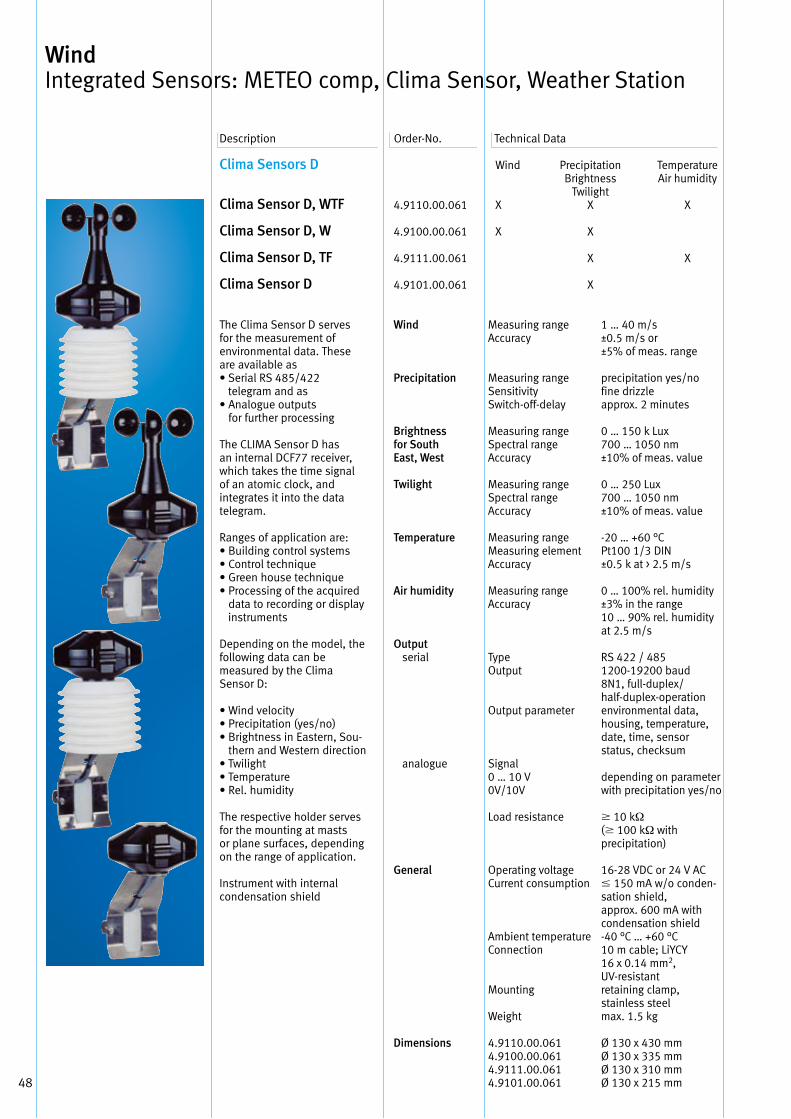
48
Clima Sensors D
Clima Sensor D, WTF
Clima Sensor D, W
Clima Sensor D, TF
Clima Sensor D
The Clima Sensor D servesfor the measurement ofenvironmental data . Theseare available as• Serial RS 485/422
telegram and as• Analogue outputs
for further processing
The CLIMA Sensor D hasan internal DCF77 receiver,which takes the time signalof an atomic clock, and integrates it into the datatelegram .
Ranges of application are:• Building control systems• Control technique• Green house technique• Processing of the acquired
data to recording or display instruments
Depending on the model, thefollowing data can bemeasured by the Clima Sensor D:
• Wind velocity• Precipitation (yes/no)• Brightness in Eastern, Sou-
thern and Western direction• Twilight• Temperature• Rel . humidity
The respective holder servesfor the mounting at mastsor plane surfaces, dependingon the range of application .
Instrument with internalcondensation shield
Description Order-No . Technical Data
Wind Integrated Sensors: METEO comp, Clima Sensor, Weather Station
Wind Precipitation Temperature Brightness Air humidity Twilight4 .9110 .00 .061 X X X
4 .9100 .00 .061 X X
4 .9111 .00 .061 X X
4 .9101 .00 .061 X
Wind Measuring range 1 … 40 m/s Accuracy ±0 .5 m/s or ±5% of meas . range
Precipitation Measuring range precipitation yes/no Sensitivity fine drizzle Switch-off-delay approx . 2 minutes Brightness Measuring range 0 … 150 k Luxfor South Spectral range 700 … 1050 nmEast, West Accuracy ±10% of meas . value Twilight Measuring range 0 … 250 Lux Spectral range 700 … 1050 nm Accuracy ±10% of meas . value Temperature Measuring range -20 … +60 °C Measuring element Pt100 1/3 DIN Accuracy ±0 .5 k at > 2 .5 m/s Air humidity Measuring range 0 … 100% rel . humidity Accuracy ±3% in the range 10 … 90% rel . humidity at 2 .5 m/sOutput serial Type RS 422 / 485 Output 1200-19200 baud 8N1, full-duplex/ half-duplex-operation Output parameter environmental data, housing, temperature, date, time, sensor status, checksum analogue Signal 0 … 10 V depending on parameter 0V/10V with precipitation yes/no Load resistance 10 kΩ ( 100 kΩ with precipitation) General Operating voltage 16-28 VDC or 24 V AC Current consumption 150 mA w/o conden- sation shield, approx . 600 mA with condensation shield Ambient temperature -40 °C … +60 °C Connection 10 m cable; LiYCY 16 x 0 .14 mm2, UV-resistant Mounting retaining clamp, stainless steel Weight max . 1 .5 kg Dimensions 4 .9110 .00 .061 Ø 130 x 430 mm 4 .9100 .00 .061 Ø 130 x 335 mm 4 .9111 .00 .061 Ø 130 x 310 mm 4 .9101 .00 .061 Ø 130 x 215 mm
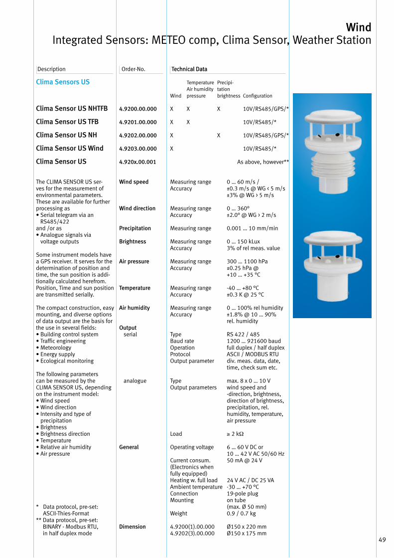
49
Description Order-No . Technical DataTechnical Data
Wind Precipitation Temperature Brightness Air humidity Twilight4 .9110 .00 .061 X X X
4 .9100 .00 .061 X X
4 .9111 .00 .061 X X
4 .9101 .00 .061 X
Wind Measuring range 1 … 40 m/s Accuracy ±0 .5 m/s or ±5% of meas . range
Precipitation Measuring range precipitation yes/no Sensitivity fine drizzle Switch-off-delay approx . 2 minutes Brightness Measuring range 0 … 150 k Luxfor South Spectral range 700 … 1050 nmEast, West Accuracy ±10% of meas . value Twilight Measuring range 0 … 250 Lux Spectral range 700 … 1050 nm Accuracy ±10% of meas . value Temperature Measuring range -20 … +60 °C Measuring element Pt100 1/3 DIN Accuracy ±0 .5 k at > 2 .5 m/s Air humidity Measuring range 0 … 100% rel . humidity Accuracy ±3% in the range 10 … 90% rel . humidity at 2 .5 m/sOutput serial Type RS 422 / 485 Output 1200-19200 baud 8N1, full-duplex/ half-duplex-operation Output parameter environmental data, housing, temperature, date, time, sensor status, checksum analogue Signal 0 … 10 V depending on parameter 0V/10V with precipitation yes/no Load resistance 10 kΩ ( 100 kΩ with precipitation) General Operating voltage 16-28 VDC or 24 V AC Current consumption 150 mA w/o conden- sation shield, approx . 600 mA with condensation shield Ambient temperature -40 °C … +60 °C Connection 10 m cable; LiYCY 16 x 0 .14 mm2, UV-resistant Mounting retaining clamp, stainless steel Weight max . 1 .5 kg Dimensions 4 .9110 .00 .061 Ø 130 x 430 mm 4 .9100 .00 .061 Ø 130 x 335 mm 4 .9111 .00 .061 Ø 130 x 310 mm 4 .9101 .00 .061 Ø 130 x 215 mm
Clima Sensors US
Clima Sensor US NHTFB
Clima Sensor US TFB
Clima Sensor US NH
Clima Sensor US Wind
Clima Sensor US
The CLIMA SENSOR US ser-ves for the measurement of environmental parameters . These are available for further processing as• Serial telegram via an
RS485/422and /or as• Analogue signals via
voltage outputs
Some instrument models have a GPS receiver . It serves for the determination of position and time, the sun position is addi-tionally calculated herefrom . Position, Time and sun position are transmitted serially .
The compact construction, easy mounting, and diverse options of data output are the basis for the use in several fields:• Building control system• Traffic engineering• Meteorology• Energy supply• Ecological monitoring
The following parameters can be measured by the CLIMA SENSOR US, depending on the instrument model:• Wind speed• Wind direction• Intensity and type of
precipitation • Brightness• Brightness direction• Temperature• Relative air humidity• Air pressure
* Data protocol, pre-set: ASCII-Thies-Format
** Data protocol, pre-set: BINARY - Modbus RTU, in half duplex mode
4.9200.00.000
4.9201.00.000
4.9202.00.000
4.9203.00.000
4.920x.00.001
Wind speed
Wind direction
Precipitation
Brightness
Air pressure
Temperature
Air humidity
Output serial
analogue
General
Dimension
Temperature Precipi- Air humidity tationWind pressure brightness Configuration
X X X 10V/RS485/GPS/*
X X 10V/RS485/*
X X 10V/RS485/GPS/*
X 10V/RS485/* As above, however**
Measuring rangeAccuracy
Measuring rangeAccuracy
Measuring range
Measuring rangeAccuracy
Measuring rangeAccuracy
Measuring rangeAccuracy
Measuring rangeAccuracy
Type Baud rate OperationProtocolOutput parameter
TypeOutput parameters
Load
Operating voltage
Current consum .(Electronics when fully equipped) Heating w . full load Ambient temperature Connection Mounting
Weight
4 .9200(1) .00 .0004 .9202(3) .00 .000
0 … 60 m/s /±0 .3 m/s @ WG < 5 m/s±3% @ WG > 5 m/s
0 … 360°±2 .0° @ WG > 2 m/s
0 .001 … 10 mm/min
0 … 150 kLux3% of rel meas . value
300 … 1100 hPa±0 .25 hPa @+10 … +35 °C
-40 … +80 °C±0 .3 K @ 25 °C
0 … 100% rel humidity±1 .8% @ 10 … 90%rel . humidity
RS 422 / 4851200 … 921600 baud full duplex / half duplexASCII / MODBUS RTUdiv . meas . data, date, time, check sum etc .
max . 8 x 0 … 10 V wind speed and -direction, brightness, direction of brightness, precipitation, rel . humidity, temperature, air pressure
≥ 2 kΩ
6 … 60 V DC or10 … 42 V AC 50/60 Hz50 mA @ 24 V
24 V AC / DC 25 VA-30 … +70 °C19-pole plugon tube(max . Ø 50 mm)0 .9 / 0 .7 kg
Ø150 x 220 mmØ150 x 175 mm
Wind Integrated Sensors: METEO comp, Clima Sensor, Weather Station
50
Accessories
Cable16-core assembled connectingcable for CLIMA SENSOR US equipment:• 19-pole cable socket,
instrument-site,• open ends receive-site,• shielded,• non-halogen,• UV-resistant
Cable8-core assembled connectingcable for the exclusively serial operation of a CLIMA SENSOR US equipment:• 19-pole cable socket,
instrument-site,• open ends, receive-site,• shielded,• non-halogen,• UV-resistant
Power Supply UnitServes for the power supply of the CLIMA SENSOR US as well as for the connection and distribution of cable resp . cable wires equipment:Toroidal transformer, series terminals, housing with cable gland .
PC ProgramThies Device UtilityFor initial operation and confi-guration of Thies-sensors with serial interface .
509311
509427
9.3389.20.000
9.1700.81.000
Length
Length
PrimarySecondary Series terminals Housing Dimension (LxWxH)
Cable gland
ProtectionWeight
see page 61
10 m
10 m
230 V AC/115 V AC24 V AC/30 VA16plasticca . 125 x 1125 x 104 mm3 x M16 x 1 .51 x M20 x 1 .5IP 66approx 1 .5 kg
Description Order-No . Technical Data
Wind Integrated Sensors: METEO comp, Clima Sensor, Weather Station
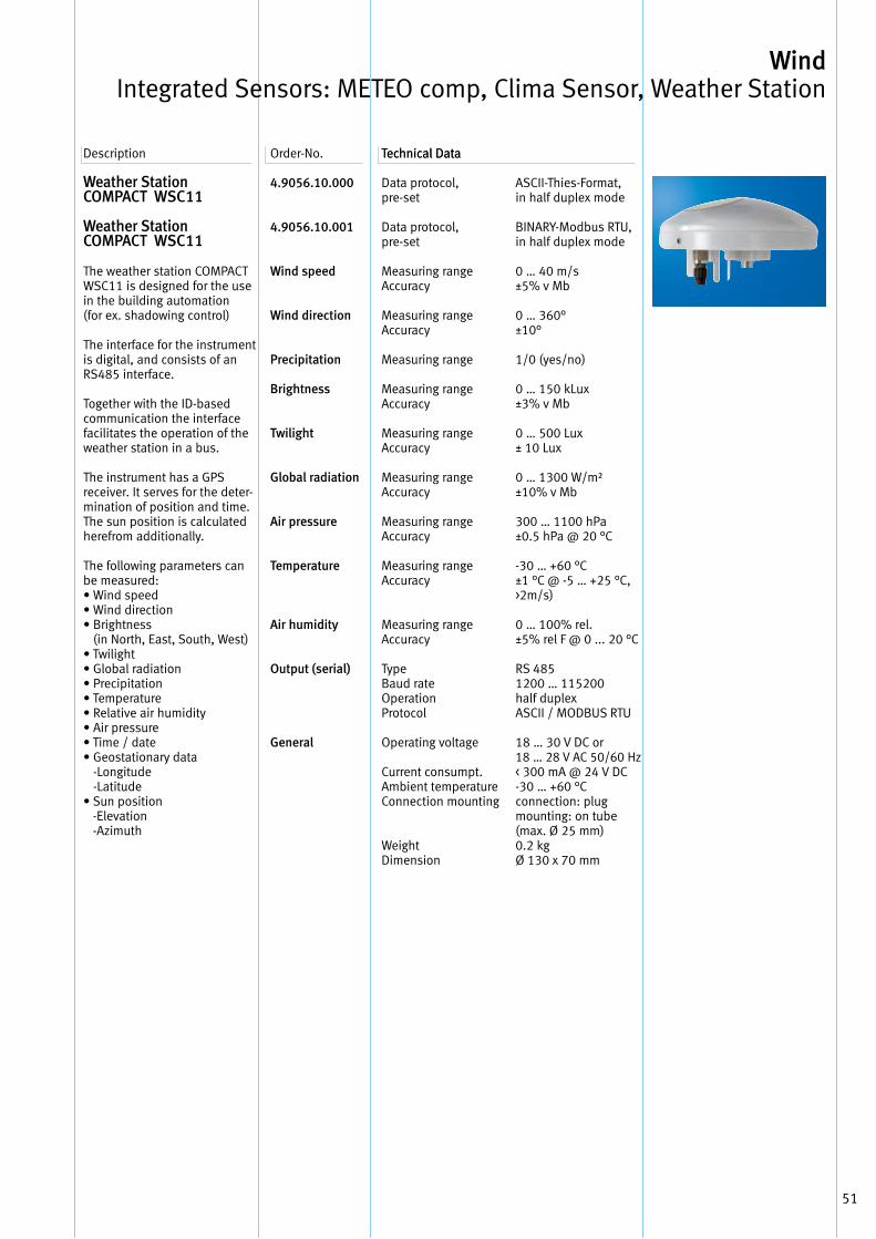
51
Weather Station COMPACT WSC11
Weather Station COMPACT WSC11
The weather station COMPACT WSC11 is designed for the use in the building automation(for ex . shadowing control)
The interface for the instrument is digital, and consists of an RS485 interface .
Together with the ID-based communication the interface facilitates the operation of the weather station in a bus .
The instrument has a GPS receiver . It serves for the deter-mination of position and time . The sun position is calculated herefrom additionally .
The following parameters can be measured:• Wind speed• Wind direction• Brightness
(in North, East, South, West)• Twilight• Global radiation• Precipitation• Temperature• Relative air humidity• Air pressure• Time / date• Geostationary data
-Longitude -Latitude
• Sun position -Elevation -Azimuth
4.9056.10.000
4.9056.10.001
Wind speed
Wind direction
Precipitation
Brightness
Twilight
Global radiation
Air pressure
Temperature
Air humidity
Output (serial)
General
Description Order-No . Technical DataTechnical Data
Data protocol, pre-set
Data protocol, pre-set
Measuring rangeAccuracy
Measuring rangeAccuracy
Measuring range
Measuring rangeAccuracy
Measuring rangeAccuracy
Measuring rangeAccuracy
Measuring rangeAccuracy
Measuring rangeAccuracy
Measuring rangeAccuracy
Type Baud rate Operation Protocol
Operating voltage
Current consumpt . Ambient temperature Connection mounting
WeightDimension
ASCII-Thies-Format, in half duplex mode
BINARY-Modbus RTU,in half duplex mode
0 … 40 m/s±5% v Mb
0 … 360°±10°
1/0 (yes/no)
0 … 150 kLux±3% v Mb
0 … 500 Lux± 10 Lux
0 … 1300 W/m²±10% v Mb
300 … 1100 hPa±0 .5 hPa @ 20 °C
-30 … +60 °C±1 °C @ -5 … +25 °C,>2m/s)
0 … 100% rel . ±5% rel F @ 0 . . . 20 °C
RS 4851200 … 115200half duplexASCII / MODBUS RTU
18 … 30 V DC or18 … 28 V AC 50/60 Hz< 300 mA @ 24 V DC-30 … +60 °C connection: plug mounting: on tube(max . Ø 25 mm)0 .2 kgØ 130 x 70 mm
Wind Integrated Sensors: METEO comp, Clima Sensor, Weather Station
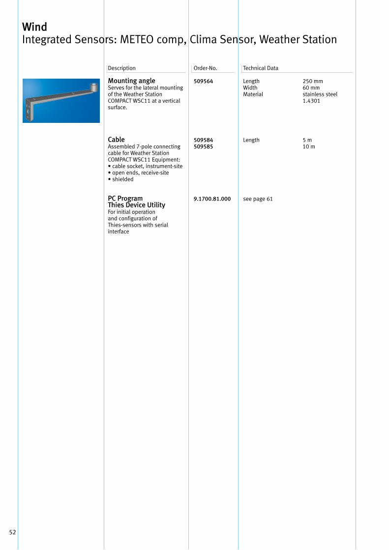
52
Mounting angleServes for the lateral mountingof the Weather Station COMPACT WSC11 at a vertical surface .
CableAssembled 7-pole connecting cable for Weather Station COMPACT WSC11 Equipment:• cable socket, instrument-site• open ends, receive-site• shielded
PC ProgramThies Device UtilityFor initial operationand configuration ofThies-sensors with serialinterface
509564
509584509585
9.1700.81.000
Length Width Material
Length
see page 61
250 mm 60 mmstainless steel 1 .4301
5 m10 m
Description Order-No . Technical Data
Wind Integrated Sensors: METEO comp, Clima Sensor, Weather Station
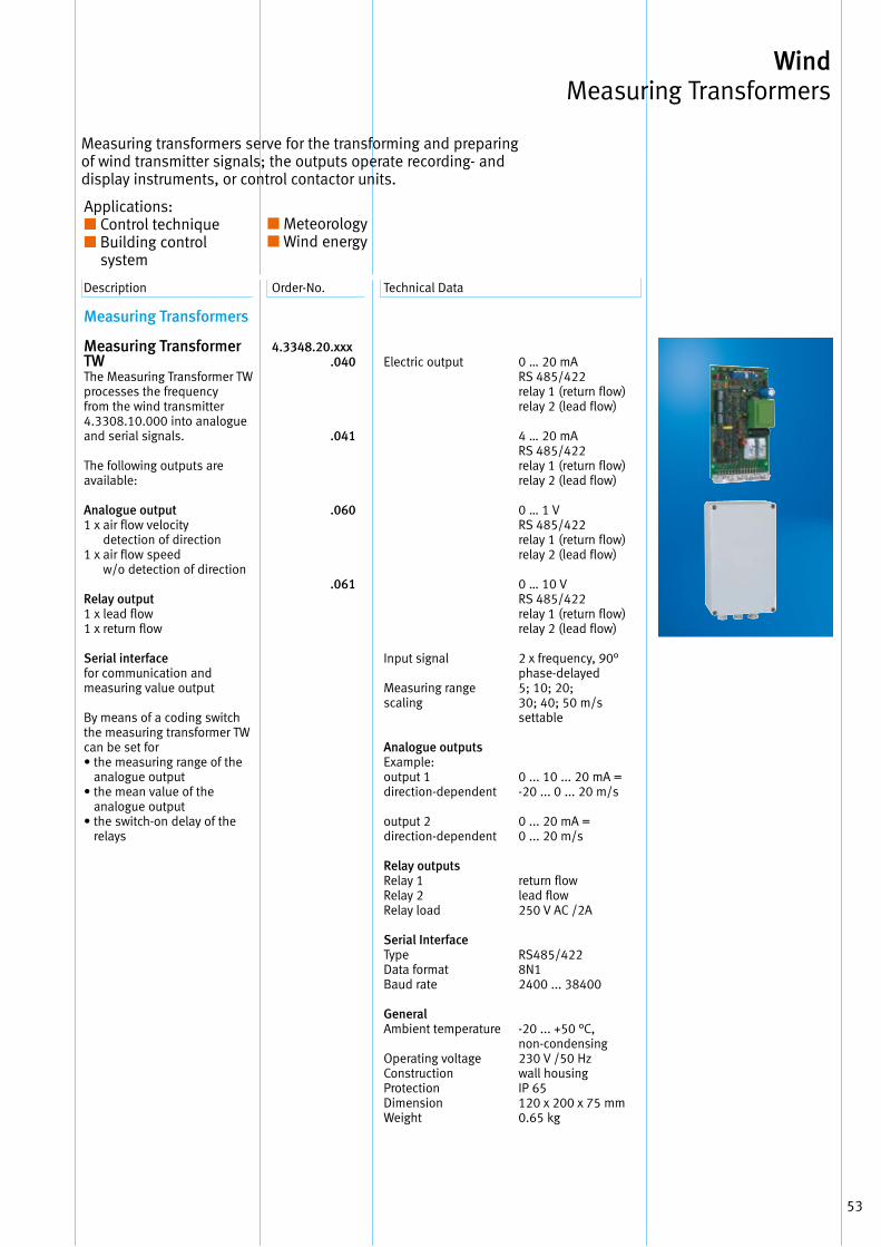
53
Wind Measuring Transformers
Description Order-No . Technical Data
Measuring transformers serve for the transforming and preparingof wind transmitter signals; the outputs operate recording- and display instruments, or control contactor units .
Applications:■ Control technique■ Building control
system ■
■ Meteorology■ Wind energy
Measuring Transformers
Measuring Transformer TW The Measuring Transformer TW processes the frequency from the wind transmitter4 .3308 .10 .000 into analogue and serial signals .
The following outputs are available:
Analogue output1 x air flow velocity
detection of direction1 x air flow speed
w/o detection of direction
Relay output1 x lead flow1 x return flow
Serial interfacefor communication and measuring value output
By means of a coding switch the measuring transformer TW can be set for• the measuring range of the
analogue output• the mean value of the
analogue output• the switch-on delay of the
relays
4.3348.20 .xxx .040 .041 .060 .061
Electric output
Input signal
Measuring range scaling
Analogue outputs Example: output 1direction-dependent
output 2 direction-dependent
Relay outputsRelay 1Relay 2Relay load
Serial InterfaceType Data format Baud rate
GeneralAmbient temperature
Operating voltageConstruction ProtectionDimension Weight
0 … 20 mA RS 485/422relay 1 (return flow)relay 2 (lead flow)
4 … 20 mA RS 485/422relay 1 (return flow)relay 2 (lead flow)
0 … 1 VRS 485/422relay 1 (return flow) relay 2 (lead flow)
0 … 10 VRS 485/422relay 1 (return flow) relay 2 (lead flow)
2 x frequency, 90°phase-delayed5; 10; 20;30; 40; 50 m/s settable
0 . . . 10 . . . 20 mA =-20 . . . 0 . . . 20 m/s
0 . . . 20 mA =0 . . . 20 m/s
return flowlead flow250 V AC /2A
RS485/4228N12400 . . . 38400
-20 . . . +50 °C,non-condensing230 V /50 Hz wall housingIP 65120 x 200 x 75 mm0 .65 kg
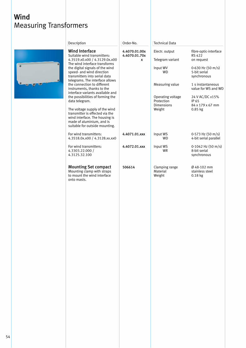
54
Wind Interface Suitable wind transmitters: 4 .3519 .x0 .x00 / 4 .3129 .0x .x00 The wind interface transforms the digital signals of the wind speed- and wind direction transmitters into serial data telegrams . The interface allows the connection to different instruments, thanks to the interface variants available and the possibilities of forming the data telegram .
The voltage supply of the wind transmitter is effected via the wind interface . The housing is made of aluminium, and is suitable for outside mounting .
For wind transmitters: 4 .3518 .0x .x00 / 4 .3128 .xx .xx0
For wind transmitters: 4 .3303 .22 .000 / 4 .3125 .32 .100
Mounting Set compact Mounting clamp with straps to mount the wind interface onto masts .
4.4070.01.00x4.4070.01.70x x
4.4071.01.xxx
4.4072.01.xxx
506614
Electr . output
Telegram variant
Input WV WD
Measuring value
Operating voltage Protection Dimensions Weight
Input WS WD
Input WS WR
Clamping range Material Weight
fibre-optic-interface RS 422 on request
0-630 Hz (50 m/s)5-bit serial synchronous
1 s instantaneous value for WS and WD
24 V AC/DC ±15%IP 6584 x 179 x 67 mm0 .85 kg
0-573 Hz (50 m/s)4-bit serial parallel
0-1042 Hz (50 m/s)8-bit serial synchronous
Ø 48-102 mmstainless steel 0 .18 kg
Description Order-No . Technical Data
Wind Measuring Transformers
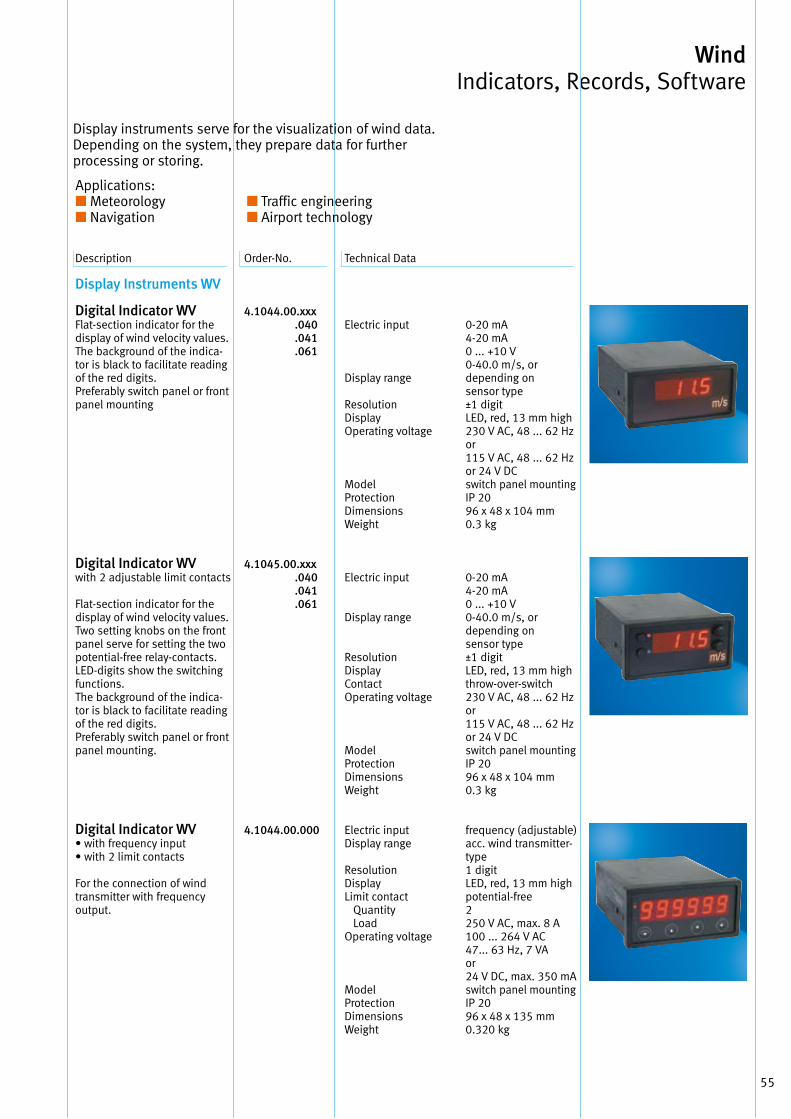
55
Wind Indicators, Records, Software
Description Order-No . Technical Data
Display Instruments WV
Digital Indicator WV Flat-section indicator for the display of wind velocity values . The background of the indica-tor is black to facilitate reading of the red digits . Preferably switch panel or front panel mounting
Digital Indicator WV with 2 adjustable limit contacts
Flat-section indicator for the display of wind velocity values . Two setting knobs on the front panel serve for setting the two potential-free relay-contacts . LED-digits show the switching functions . The background of the indica-tor is black to facilitate reading of the red digits . Preferably switch panel or front panel mounting .
Digital Indicator WV • with frequency input• with 2 limit contacts
For the connection of wind transmitter with frequency output .
4.1044.00.xxx .040 .041 .061
4.1045.00.xxx .040 .041 .061
4.1044.00.000
Electric input
Display range
Resolution Display Operating voltage
Model Protection Dimensions Weight
Electric input
Display range
Resolution Display Contact Operating voltage
Model Protection Dimensions Weight
Electric input Display range
ResolutionDisplayLimit contact Quantity LoadOperating voltage
Model Protection Dimensions Weight
0-20 mA4-20 mA0 . . . +10 V0-40 .0 m/s, or depending on sensor type ±1 digitLED, red, 13 mm high230 V AC, 48 . . . 62 Hzor115 V AC, 48 . . . 62 Hz or 24 V DCswitch panel mounting IP 2096 x 48 x 104 mm0 .3 kg
0-20 mA4-20 mA0 . . . +10 V0-40 .0 m/s, or depending on sensor type ±1 digitLED, red, 13 mm highthrow-over-switch 230 V AC, 48 . . . 62 Hzor115 V AC, 48 . . . 62 Hz or 24 V DCswitch panel mountingIP 2096 x 48 x 104 mm0 .3 kg
frequency (adjustable) acc . wind transmitter- type1 digitLED, red, 13 mm highpotential-free2250 V AC, max . 8 A100 . . . 264 V AC47 . . . 63 Hz, 7 VA or24 V DC, max . 350 mAswitch panel mounting IP 20 96 x 48 x 135 mm 0 .320 kg
Display instruments serve for the visualization of wind data . Depending on the system, they prepare data for further processing or storing .
Applications: ■ Meteorology■ Navigation
■ ■ Traffic engineering■ ■ Airport technology
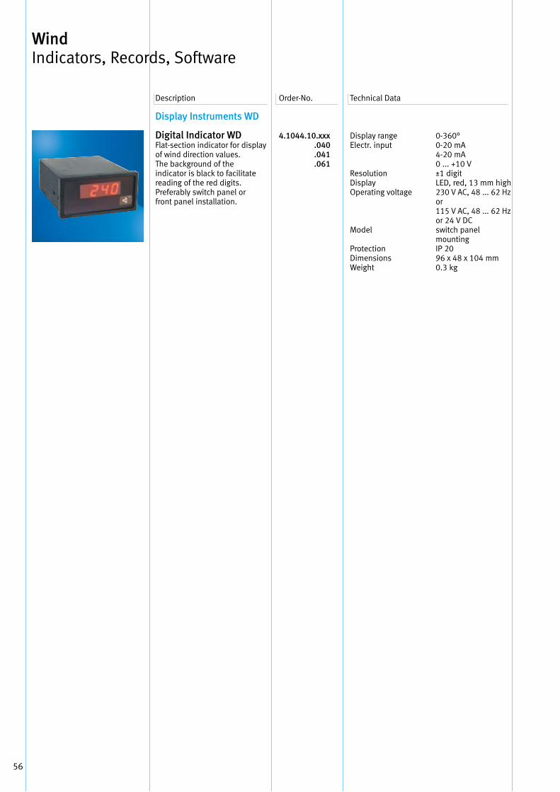
56
Display Instruments WD
Digital Indicator WD Flat-section indicator for display of wind direction values . The background of the indicator is black to facilitate reading of the red digits . Preferably switch panel or front panel installation .
4.1044.10.xxx .040 .041 .061
Display range Electr . input
Resolution Display Operating voltage
Model
Protection Dimensions Weight
0-360°0-20 mA4-20 mA0 . . . +10 V±1 digitLED, red, 13 mm high230 V AC, 48 . . . 62 Hzor115 V AC, 48 . . . 62 Hz or 24 V DCswitch panel mounting IP 2096 x 48 x 104 mm0 .3 kg
Description Order-No . Technical Data
Wind Indicators, Records, Software
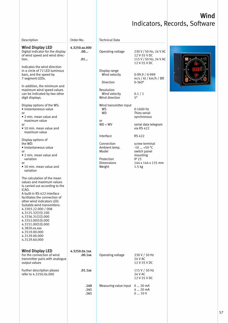
57
Wind Indicators, Records, Software
Wind Display LEDDigital indicator for the display of wind speed and wind direc-tion .
Indicates the wind direction in a circle of 72 LED luminous bars, and the speed by 7-segment-LEDs .
In addition, the minimum and maximum wind speed values can be indicated by two other digit displays .
Display options of the WS: • instantaneous value or • 2 min . mean value and
maximum value or • 10 min . mean value and
maximum value
Display options of the WD: • instantaneous value or • 2 min . mean value and
variation or • 10 min . mean value and
variation
The calculation of the mean values and maximum values is carried out according to the ICAO . A built-in RS-422-interface facilitates the connection of other wind indicators LED: Suitable wind transmitters: 4 .3303 .22 .000 / 0084 .3125 .32(33) .1004 .3336 .31(32) .0004 .3352 .00(10) .0004 .3151 .00(10) .0004 .3820 .xx .xxx4 .3519 .00 .0004 .3129 .00 .0004 .3129 .60 .000
Wind Display LEDFor the connection of windtransmitter pairs with analogueoutput values
Further description please refer to 4 .3250 .0x .000
4.3250.xx.000 .00... .01...
4.3250.0x.1xx .00.1xx
.01.1xx
.140 .141 .161
Description Order-No . Technical Data
Operating voltage
Display range Wind velocity
Direction
Resolution Wind velocityWind direction
Wind transmitter input WS WD
or WD + WV
Interface
Connection Ambient temp . Model
Protection Dimensions Weight
Operating voltage
Measuring value input
230 V / 50 Hz; 24 V AC12 V-35 V DC115 V / 50 Hz; 24 V AC12 V-35 V DC
0-99 .9 / 0-999 m/s / kt / km/h / Bft0-360°
0 .1 / 15°
0-1600 HzThies-serial- synchronous
serial data telegram via RS 422
RS 422
screw terminal -10 . . . +50 °Cswitch panel mounting IP 23144 x 144 x 135 mm1 .5 kg
230 V / 50 Hz 24 V AC 12 V-35 V DC
115 V / 50 Hz24 V AC 12 V-35 V DC
0 … 20 mA4 … 20 mA0 . . . 10 V
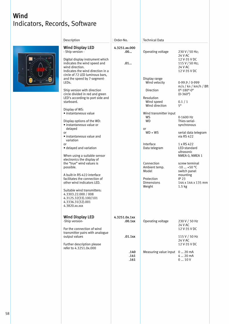
58
Wind Display LED - Ship version -
Digital display instrument which indicates the wind speed and wind direction . Indicates the wind direction in a circle of 72 LED luminous bars, and the speed by 7-segment-LEDs .
Ship version with direction circle divided in red and green LED’s according to port side and starboard .
Display of WS: • instantaneous value Display options of the WD: • instantaneous value or
delayed or • instantaneous value and
variation or • delayed and variation
When using a suitable sensor electronics the display of the “true” wind values is possible .
A built-in RS-422-interface facilitates the connection of other wind indicators LED .
Suitable wind transmitters: 4 .3303 .22 .000 / 008 4 .3125 .32(33) .100/1014 .3336 .31(32) .0014 .3820 .xx .xxx
Wind Display LED -Ship version-
For the connection of wind transmitter pairs with analogue output values
Further description please refer to 4 .3251 .0x .000
4.3251.xx.000 .00...
.01...
4.3251.0x.1xx .00.1xx
.01.1xx
.140 .141 .161
Operating voltage
Display range Wind velocity
Direction
Resolution Wind speed Wind direction
Wind transmitter input WS WD
or WD + WS
Interface Data telegram
Connection Ambient temp . Model
Protection Dimensions Weight
Operating voltage
Measuring value input
230 V / 50 Hz; 24 V AC12 V-35 V DC115 V / 50 Hz; 24 V AC12 V-35 V DC
0-99 .9 / 0-999 m/s / kn / km/h / Bft0°-180°-0° (0-360°) 0 .1 / 15°
0-1600 HzThies-serial- synchronous
serial data telegram via RS 422
1 x RS 422LED-standard ultrasonic NMEA 0, NMEA 1
screw terminal -10 . . . +50 °Cswitch panel mounting IP 23144 x 144 x 135 mm1 .5 kg
230 V / 50 Hz 24 V AC12 V-35 V DC
115 V / 50 Hz24 V AC12 V-35 V DC
0 … 20 mA 4 … 20 mA0 . . . 10 V
Description Order-No . Technical Data
Wind Indicators, Records, Software
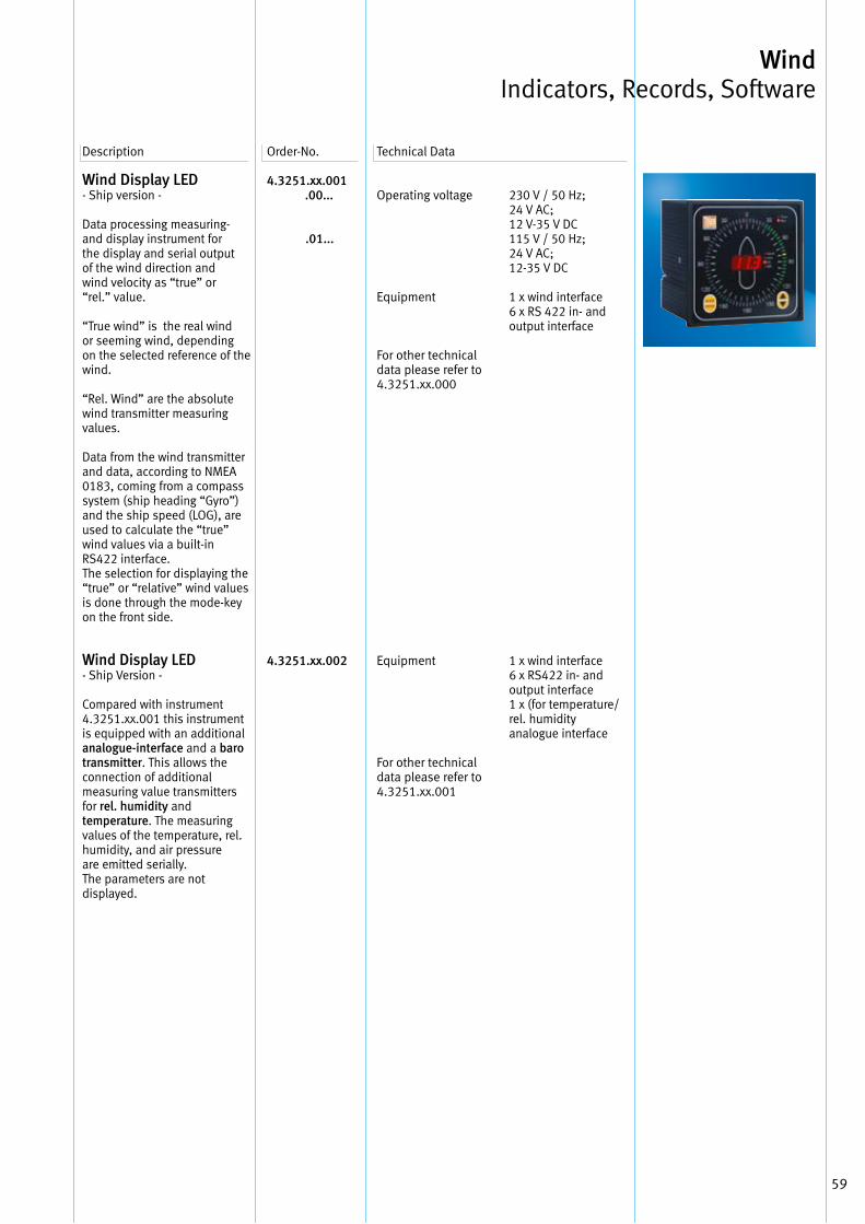
59
Wind Indicators, Records, Software
Wind Display LED - Ship version -
Data processing measuring-and display instrument forthe display and serial outputof the wind direction andwind velocity as “true” or“rel .” value .
“True wind” is the real windor seeming wind, dependingon the selected reference of the wind .
“Rel . Wind” are the absolutewind transmitter measuring values .
Data from the wind transmitter and data, according to NMEA 0183, coming from a compass system (ship heading “Gyro”) and the ship speed (LOG), are used to calculate the “true” wind values via a built-in RS422 interface . The selection for displaying the “true” or “relative” wind values is done through the mode-key on the front side .
Wind Display LED - Ship Version -
Compared with instrument 4 .3251 .xx .001 this instrument is equipped with an additionalanalogue-interface and a baro transmitter . This allows theconnection of additional measuring value transmittersfor rel. humidity and temperature . The measuringvalues of the temperature, rel .humidity, and air pressureare emitted serially .The parameters are not displayed .
4.3251.xx.001 .00...
.01...
4.3251.xx.002
Description Order-No . Technical Data
Operating voltage
Equipment
For other technical data please refer to4 .3251 .xx .000
Equipment
For other technical data please refer to4 .3251 .xx .001
230 V / 50 Hz; 24 V AC;12 V-35 V DC115 V / 50 Hz; 24 V AC;12-35 V DC
1 x wind interface6 x RS 422 in- andoutput interface
1 x wind interface6 x RS422 in- andoutput interface1 x (for temperature/rel . humidityanalogue interface
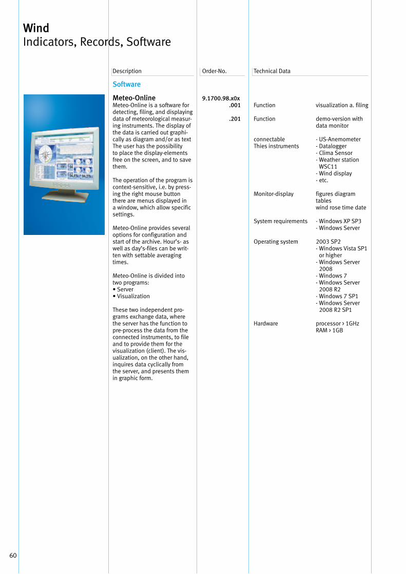
60
Software
Meteo-OnlineMeteo-Online is a software for detecting, filing, and displaying data of meteorological measur-ing instruments . The display of the data is carried out graphi-cally as diagram and/or as text The user has the possibility to place the display-elements free on the screen, and to save them .
The operation of the program is context-sensitive, i .e . by press-ing the right mouse button there are menus displayed in a window, which allow specific settings .
Meteo-Online provides several options for configuration and start of the archive . Hour’s- as well as day’s-files can be writ-ten with settable averaging times .
Meteo-Online is divided into two programs:• Server• Visualization
These two independent pro-grams exchange data, where the server has the function to pre-process the data from the connected instruments, to file and to provide them for the visualization (client) . The vis-ualization, on the other hand, inquires data cyclically from the server, and presents them in graphic form .
9.1700.98 .x0x .001 .201
Function
Function
connectableThies instruments
Monitor-display
System requirements
Operating system
Hardware
visualization a . filing
demo-version with data monitor
- US-Anemometer- Datalogger- Clima Sensor- Weather station
WSC11- Wind display- etc .
figures diagram tables wind rose time date
- Windows XP SP3- Windows Server
2003 SP2- Windows Vista SP1
or higher- Windows Server
2008 - Windows 7- Windows Server
2008 R2 - Windows 7 SP1- Windows Server
2008 R2 SP1
processor > 1GHzRAM > 1GB
Description Order-No . Technical Data
Wind Indicators, Records, Software
61
Wind Indicators, Records, Software
Thies Device UtilityThe PC program “Thies Device Utility” serves for the initial operation and configuration of Thies sensors with serial interface .The program can find all sen-sors connected to the PC, and facilitates an initial operation via terminal function . Thanks to a user-friendly surface design the communication with the sensors is very easy .
Functions:1 Searching for sensors:- Selection of serial interface- Selection of baud rates for
the search- Selection of bus addresses
for the search- Setting of delays in the com-
munication with the interface transformer (RS485/422)
2 Display / operation:- Selection of interpreter
“THIES” or “MODBUS-RTU”- Terminal function to
“Thies Interpreter”- Terminal function to
“MODBUS-RTU Interpreter”- Tabular presentation of the
instantaneous measuring values .
9.1700.81.000
Description Order-No . Technical Data
Function
Connectable Instru-ments, Examples
System requirements Operating system
searching for Thies-sensors settings for the communication monitor-presentation of instantaneous measuring values and settings
Weather Station Compact WSC114 .9056 .00 .000Clima Sensor US4 .920x .00 .000US-Anemometer 2D4 .38xx .xx .xxxUS-Anemometer 3D4 .3830 .xx .xxxUS-Anemometer 2Dcompact4 .3875 .xx .xxx
Windows XP or higher

62
Your Notice
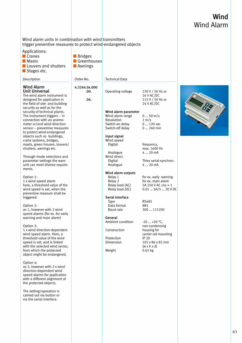
63
Description Order-No . Technical Data
Wind Alarm Unit Universal The wind alarm instrument is designed for application in the field of site- and building security as well as for the security of technical plants .The instrument triggers – in connection with an anemo-meter or/and wind direction sensor – preventive measures to protect wind-endangered objects such as buildings, crane systems, bridges, masts, green houses, louvers/ shutters, awnings etc .
Through mode selections and parameter settings the warn unit can meet diverse require-ments .
Option 1:1 x wind speed alarmhere, a threshold value of the wind speed is set, when the preventive measure shall be triggered .
Option 2:as 1, however with 2 wind speed alarms (for ex . for early warning and main alarm)
Option 3:1 x wind direction-dependent wind speed alarm . Here, a threshold value of the wind speed is set, and is linked with the selected wind sector, from which the protected object might be endangered .
Option 4:as 3, however with 2 x wind direction-dependent wind speed alarms for application with a different alignment of the protected objects .
The setting/operation is carried out via button or via the serial interface .
4.3244 .0x.000 .00. .04.
Operating voltage
Wind alarm parameter Wind alarm range Resolution Switch-on delay Switch-off delay
Input signalWind speed Digital
AnalogueWind direct . Digital Analogue
Wind alarm outputs Relay 1 Relay 2 Relay load (AC) Relay load (DC) Serial interface Type Data format Baud rate
GeneralAmbient condition
Construction
ProtectionDimension
Weight
230 V / 50 Hz or 24 V AC/DC115 V / 50 Hz or 24 V AC/DC
0 . . . 50 m/s1 m/s0 . . . 120 sec0 . . . 240 min
frequency,max . 1600 Hz4 . . . 20 mA
Thies serial-synchron .4 . . . 20 mA
for ex . early warningfor ex . main alarm5A 250 V AC cos = 10 .01 … 5A/5 … 30 V DC
RS4858N1300 . . . 115200
-20 . . . +50 °C,non-condensing housing for carrier rail mounting IP 20105 x 86 x 85 mm(w x h x d)0 .65 kg
Wind alarm units in combination with wind transmitterstrigger preventive measures to protect wind-endangered objects
Applications:■ Cranes ■ Bridges■ Masts ■ Greenhouses■ Louvers and shutters ■ Awnings■ Stages etc .
Wind Wind Alarm

Your Notice
64
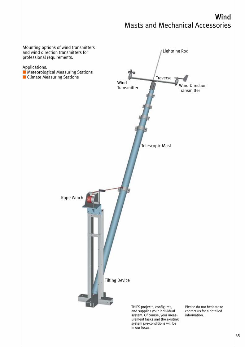
THIES projects, configures, and supplies your individual system . Of course, your meas-urement tasks and the existing system pre-conditions will be in our focus .
Please do not hesitate to contact us for a detailed information .
Wind Masts and Mechanical Accessories
Mounting options of wind transmittersand wind direction transmitters for professional requirements .
Applications: ■ Meteorological Measuring Stations■ Climate Measuring Stations
Lightning Rod
Wind Direction Transmitter
Telescopic Mast
Rope Winch
Tilting Device
Wind Transmitter
Traverse
65
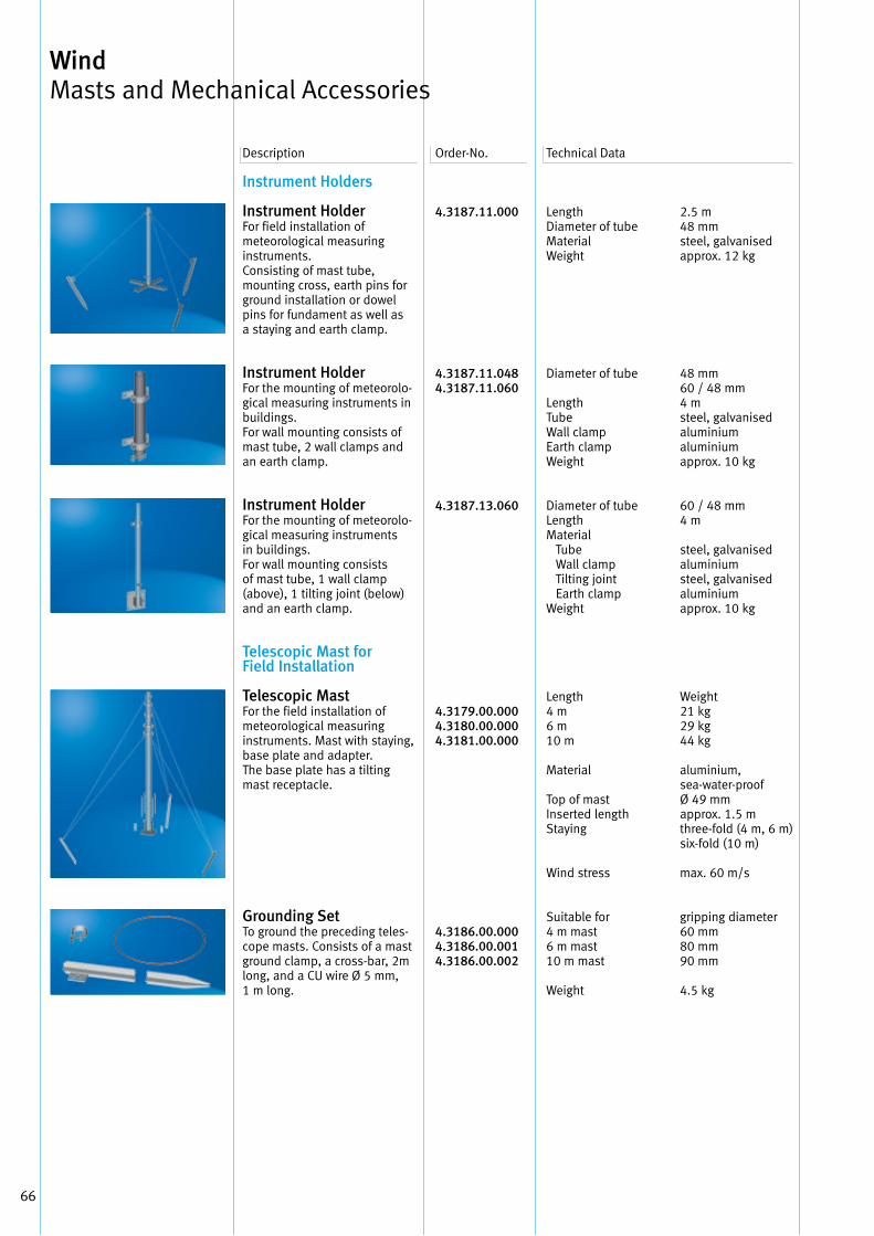
66
4.3187.11.000
4.3187.11.0484.3187.11.060
4.3187.13.060
4.3179.00.0004.3180.00.0004.3181.00.000
4.3186.00.0004.3186.00.0014.3186.00.002
Length Diameter of tube Material Weight
Diameter of tube
Length TubeWall clampEarth clampWeight
Diameter of tubeLength Material Tube Wall clamp Tilting joint Earth clampWeight
Length 4 m 6 m 10 m
Material
Top of mast Inserted length Staying
Wind stress
Suitable for 4 m mast 6 m mast 10 m mast
Weight
2 .5 m48 mmsteel, galvanisedapprox . 12 kg
48 mm60 / 48 mm4 m steel, galvanised aluminium aluminiumapprox . 10 kg
60 / 48 mm4 m
steel, galvanisedaluminiumsteel, galvanisedaluminiumapprox . 10 kg
Weight21 kg29 kg44 kg
aluminium, sea-water-proof Ø 49 mmapprox . 1 .5 mthree-fold (4 m, 6 m)six-fold (10 m)
max . 60 m/s
gripping diameter60 mm 80 mm 90 mm
4 .5 kg
Description Order-No . Technical Data
Wind Masts and Mechanical Accessories
Instrument Holders
Instrument HolderFor field installation of meteorological measuring instruments . Consisting of mast tube, mounting cross, earth pins for ground installation or dowel pins for fundament as well as a staying and earth clamp .
Instrument HolderFor the mounting of meteorolo-gical measuring instruments in buildings . For wall mounting consists of mast tube, 2 wall clamps and an earth clamp .
Instrument Holder For the mounting of meteorolo-gical measuring instruments in buildings . For wall mounting consists of mast tube, 1 wall clamp (above), 1 tilting joint (below) and an earth clamp .
Telescopic Mast for Field Installation
Telescopic Mast For the field installation of meteorological measuring instruments . Mast with staying, base plate and adapter . The base plate has a tilting mast receptacle .
Grounding Set To ground the preceding teles-cope masts . Consists of a mast ground clamp, a cross-bar, 2m long, and a CU wire Ø 5 mm, 1 m long .
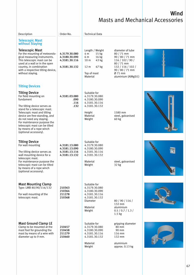
67
Wind Masts and Mechanical Accessories
Telescopic Mast without Staying
Telescopic Mast For the mounting of meteorolo-gical measuring instruments . This telescopic mast can be used at a wall or in the open country, in combination with a respective tilting device, without staying .
Tilting Devices
Tilting Device For field mounting on fundament
The tilting device serves as stand for a telescopic mast . Telescopic mast and tilting device are free-standing, and do not need any staying . For maintenance purpose the telescopic mast can be tilted by means of a rope winch (optional accessory) .
Tilting Device For wall mounting
The tilting device serves as wall mounting device for a telescopic mast . For maintenance purpose the telescopic mast can be tilted by means of a rope winch (optional accessory) .
Mast Mounting Clamp Type: LMB 80/90/116/132
For wall mounting of the telescopic mast .
Mast Ground Clamp LE Clamp to be mounted at the mast foot for grounding the mast by means of a wire with diameter up to 9 mm .
4.3179.30.0804.3180.30.0904.3181.30.116
4.3181.30.132
4.3181.03.080 .090 .116 .132
4.3181.13.0804.3181.13.0904.3181.13.1164.3181.13.132
210363210364211278210368
210457210458211279210460
Description Order-No . Technical Data
Length / Weight4 m 15 kg6 m 16 kg10 m 43 kg
12 m 67 kg
Top of mast Material
Suitable for 4 .3179 .30 .080 4 .3180 .30 .090 4 .3181 .30 .116 4 .3181 .30 .132
Height Material Weight
Suitable for 4 .3179 .30 .080 4 .3180 .30 .090 4 .3181 .30 .116 4 .3181 .30 .132
Material Weight
Suitable for 4 .3179 .30 .080 4 .3180 .30 .090 4 .3181 .30 .116 4 .3181 .30 .132 Diameter
Material Weight
Suitable for 4 .3179 .30 .080 4 .3180 .30 .090 4 .3181 .30 .116 4 .3181 .30 .132
Material Weight
diameter of tube80 / 71 mm90 / 80 / 71 mm116 / 102 / 90 / 80 / 71 mm132 / 116 / 102 / 90 / 80 / 71 mmØ 71 mmaluminium (AlMgSi1)
1580 mmsteel, galvanised60 kg
steel, galvanised32 kg
80 / 90 / 116 / 132 mmaluminium0 .5 / 0 .7 / 1 .3 / 1 .5 kg
gripping diameter 80 mm 90 mm116 mm132 mm
aluminiumapprox . 0 .13 kg
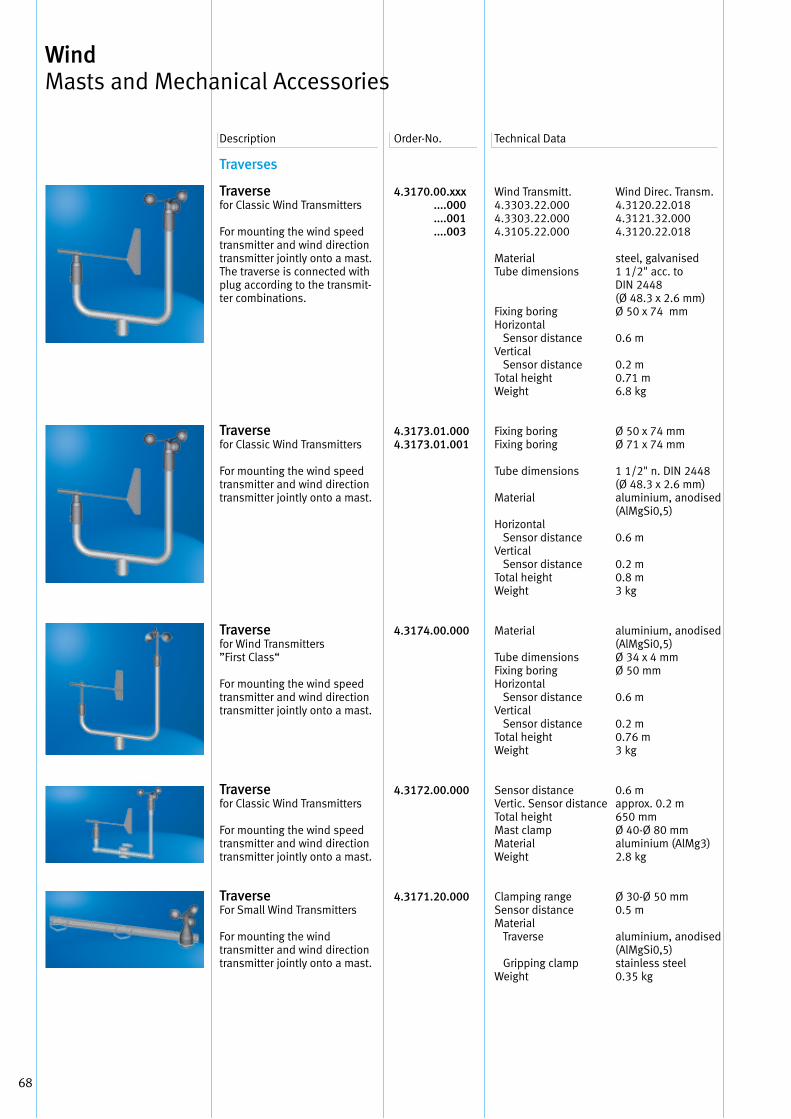
68
4.3170.00.xxx ....000 ....001 ....003
4.3173.01.0004.3173.01.001
4.3174.00.000
4.3172.00.000
4.3171.20.000
Wind Transmitt . 4 .3303 .22 .000 4 .3303 .22 .000 4 .3105 .22 .000
Material Tube dimensions
Fixing boring Horizontal Sensor distance Vertical Sensor distance Total height Weight
Fixing boring Fixing boring
Tube dimensions
Material
Horizontal Sensor distance Vertical Sensor distance Total height Weight
Material
Tube dimensionsFixing boringHorizontal Sensor distanceVertical Sensor distanceTotal heightWeight
Sensor distance Vertic . Sensor distance Total height Mast clamp Material Weight
Clamping range Sensor distance Material Traverse Gripping clamp Weight
Wind Direc . Transm .4 .3120 .22 .0184 .3121 .32 .0004 .3120 .22 .018
steel, galvanised1 1/2" acc . to DIN 2448(Ø 48 .3 x 2 .6 mm)Ø 50 x 74 mm
0 .6 m
0 .2 m0 .71 m6 .8 kg
Ø 50 x 74 mmØ 71 x 74 mm
1 1/2" n . DIN 2448 (Ø 48 .3 x 2 .6 mm) aluminium, anodised(AlMgSi0,5)
0 .6 m
0 .2 m 0 .8 m 3 kg
aluminium, anodised(AlMgSi0,5)Ø 34 x 4 mmØ 50 mm
0 .6 m
0 .2 m 0 .76 m 3 kg
0 .6 mapprox . 0 .2 m650 mmØ 40-Ø 80 mmaluminium (AlMg3)2 .8 kg
Ø 30-Ø 50 mm0 .5 m
aluminium, anodised(AlMgSi0,5)stainless steel 0 .35 kg
Description Order-No . Technical Data
Wind Masts and Mechanical Accessories
Traverses
Traversefor Classic Wind Transmitters
For mounting the wind speed transmitter and wind direction transmitter jointly onto a mast . The traverse is connected with plug according to the transmit-ter combinations .
Traversefor Classic Wind Transmitters
For mounting the wind speed transmitter and wind direction transmitter jointly onto a mast .
Traverse for Wind Transmitters ”First Class“
For mounting the wind speed transmitter and wind direction transmitter jointly onto a mast .
Traversefor Classic Wind Transmitters
For mounting the wind speed transmitter and wind direction transmitter jointly onto a mast .
TraverseFor Small Wind Transmitters
For mounting the wind transmitter and wind direction transmitter jointly onto a mast .
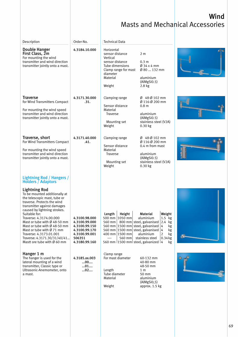
69
Wind Masts and Mechanical Accessories
Double HangerFirst Class, 2mFor mounting the wind transmitter and wind direction transmitter jointly onto a mast .
Traversefor Wind Transmitters Compact
For mounting the wind speed transmitter and wind direction transmitter jointly onto a mast .
Traverse, short For Wind Transmitters Compact
For mounting the wind speed transmitter and wind direction transmitter jointly onto a mast .
Lightning Rod / Hangers / Holders / Adaptors
Lightning Rod To be mounted additionally at the telescopic mast, tube or traverse . Protects the wind transmitter against damages caused by lightning strokes . Suitable for: Traverse: 4 .3174 .00 .000Mast or tube with Ø 48-50 mm Mast or tube with Ø 48-50 mm Mast or tube with Ø 71 mm Traverse: 4 .3173 .01 .001Traverse: 4 .3171 .30/31/40/41…Mastt ore tube with Ø 60 mm
Hanger 1 mThe hanger is used for the lateral mounting of a wind transmitter, Classic type or Ultrasonic-Anemometer, onto a mast .
4.3184.10.000
4.3171.30.000 .31.
4.3171.40.000 .41.
4.3100.98.0004.3100.99.0004.3100.99.1504.3100.99.1704.3100.99.0015063514.3180.99.160
4.3185.xx.003 ...00.... ...01.... ...02....
Description Order-No . Technical Data
Horizontal sensor distance Vertical sensor distance Tube dimensions Clamp range for mast diameter Material
Weight
Clamping range
Sensor distance Material Traverse
Mounting set Weight
Clamping range
Sensor distance Material Traverse
Mounting set Weight
Clamp range For mast diameter
LengthTube diameterMaterial
Weight
2 m
0 .3 mØ 34 x 4 mmØ 80 . . . 132 mm
aluminium(AlMgSi0 .5)2 .8 kg
Ø 48-Ø 102 mmØ 116-Ø 200 mm0 .8 m
aluminium (AlMgSi0 .5)stainless steel (V2A)0 .30 kg
Ø 48-Ø 102 mmØ 116-Ø 200 mm0 .4 m from mast
aluminium(AlMgSi0 .5)stainless steel (V2A)0 .30 kg
60-132 mm40-80 mm48-50 mm1 m50 mmaluminium (AlMgSi0,5)approx . 1 .5 kg
Length Height Material Weight500 mm 1050 mm aluminium 1 .5 kg 560 mm 800 mm steel, galvanised 2 .4 kg 560 mm 1500 mm steel, galvanised 4 kg 560 mm 1500 mm steel, galvanised 4 kg 400 mm 1500 mm aluminium 2 kg ---- 560 mm stainless steel 0 .34 kg560 mm 1500 mm steel, galvanized 4 kg
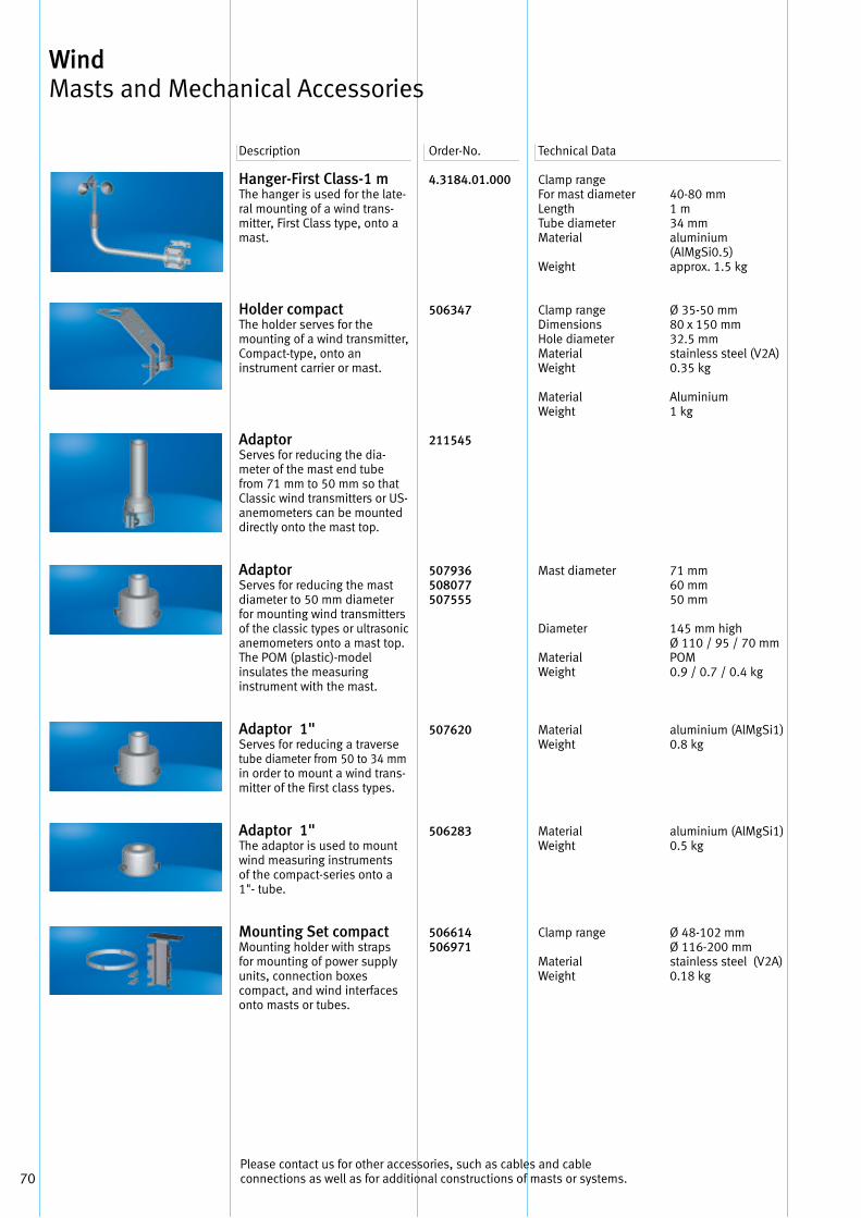
70
Hanger-First Class-1 m The hanger is used for the late-ral mounting of a wind trans-mitter, First Class type, onto a mast .
Holder compactThe holder serves for the mounting of a wind transmitter,Compact-type, onto an instrument carrier or mast .
Adaptor Serves for reducing the dia-meter of the mast end tube from 71 mm to 50 mm so that Classic wind transmitters or US-anemometers can be mounted directly onto the mast top .
Adaptor Serves for reducing the mastdiameter to 50 mm diameter for mounting wind transmitters of the classic types or ultrasonic anemometers onto a mast top .The POM (plastic)-model insulates the measuring instrument with the mast .
Adaptor 1" Serves for reducing a traversetube diameter from 50 to 34 mmin order to mount a wind trans-mitter of the first class types .
Adaptor 1"The adaptor is used to mount wind measuring instruments of the compact-series onto a 1"- tube .
Mounting Set compactMounting holder with straps for mounting of power supply units, connection boxes compact, and wind interfaces onto masts or tubes .
4.3184.01.000
506347
211545
507936508077507555
507620
506283
506614506971
Clamp rangeFor mast diameterLength Tube diameterMaterial
Weight
Clamp rangeDimensionsHole diameterMaterial Weight
Material Weight
Mast diameter
Diameter
MaterialWeight
MaterialWeight
MaterialWeight
Clamp range
MaterialWeight
40-80 mm1 m34 mmaluminium (AlMgSi0 .5)approx . 1 .5 kg
Ø 35-50 mm80 x 150 mm32 .5 mmstainless steel (V2A)0 .35 kg
Aluminium1 kg
71 mm 60 mm50 mm
145 mm high Ø 110 / 95 / 70 mmPOM0 .9 / 0 .7 / 0 .4 kg
aluminium (AlMgSi1)0 .8 kg
aluminium (AlMgSi1)0 .5 kg
Ø 48-102 mm Ø 116-200 mm stainless steel (V2A)0 .18 kg
Description Order-No . Technical Data
Wind Masts and Mechanical Accessories
Please contact us for other accessories, such as cables and cableconnections as well as for additional constructions of masts or systems .
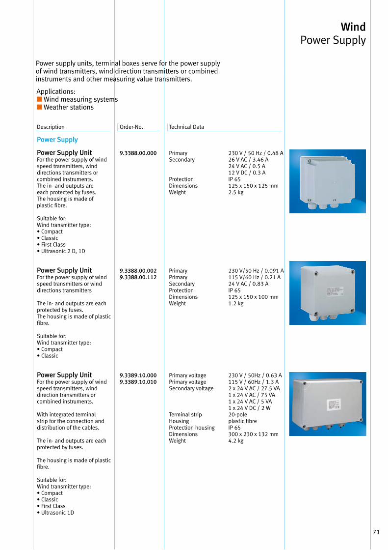
71
Description Order-No . Technical Data
Power Supply
Power Supply Unit For the power supply of wind speed transmitters, wind directions transmitters or combined instruments . The in- and outputs are each protected by fuses . The housing is made of plastic fibre .
Suitable for: Wind transmitter type: • Compact• Classic• First Class• Ultrasonic 2 D, 1D
Power Supply Unit For the power supply of wind speed transmitters or wind directions transmitters
The in- and outputs are each protected by fuses . The housing is made of plastic fibre .
Suitable for: Wind transmitter type: • Compact• Classic
Power Supply Unit For the power supply of wind speed transmitters, wind direction transmitters or combined instruments .
With integrated terminal strip for the connection and distribution of the cables .
The in- and outputs are each protected by fuses .
The housing is made of plastic fibre .
Suitable for: Wind transmitter type: • Compact• Classic• First Class• Ultrasonic 1D
9.3388.00.000
9.3388.00.002 9.3388.00.112
9.3389.10.000 9.3389.10.010
Primary Secondary
Protection Dimensions Weight
Primary Primary Secondary Protection Dimensions Weight
Primary voltage Primary voltage Secondary voltage
Terminal strip Housing Protection housing Dimensions Weight
230 V / 50 Hz / 0 .48 A 26 V AC / 3 .46 A24 V AC / 0 .5 A12 V DC / 0 .3 AIP 65125 x 150 x 125 mm 2 .5 kg
230 V/50 Hz / 0 .091 A115 V/60 Hz / 0 .21 A24 V AC / 0 .83 A IP 65 125 x 150 x 100 mm 1 .2 kg
230 V / 50Hz / 0 .63 A115 V / 60Hz / 1 .3 A2 x 24 V AC / 27 .5 VA1 x 24 V AC / 75 VA1 x 24 V AC / 5 VA1 x 24 V DC / 2 W20-pole plastic fibreIP 65 300 x 230 x 132 mm 4 .2 kg
Power supply units, terminal boxes serve for the power supply of wind transmitters, wind direction transmitters or combined instruments and other measuring value transmitters .
Applications: ■ Wind measuring systems■ Weather stations
Wind Power Supply
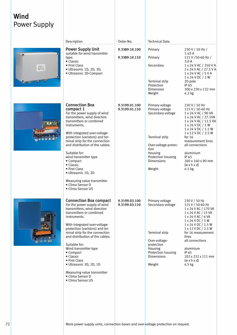
72
Power Supply Unitsuitable for wind transmitter type:• Classic• First Class• Ultrasonic 1D, 2D, 3D,• Ultrasonic 2D-Compact
Connection Box compact 1 For the power supply of wind transmitters, wind directiontransmitters or combined instruments .
With integrated over-voltage-protection (varistors) and ter-minal strip for the connection and distribution of the cables .
Suitable for: wind transmitter type• Compact• Classic• First Class• Ultrasonic 1D, 2D
Measuring value transmitter• Clima Sensor D• Clima Sensor US
Connection Box compact For the power supply of wind transmitters, wind directiontransmitters or combined instruments .
With integrated over-voltage-protection (varistors) and ter-minal strip for the connection and distribution of the cables .
Suitable for: Wind transmitter type• Compact• Classic• First Class• Ultrasonic 3D, 2D, 1D
Measuring value transmitter• Clima Sensor D• Clima Sensor US
9.3389.10.100
9.3389.10.110
9.3199.01.100 9.3199.01.110
9.3199.03.100 9.3199.03.110
Primary
Primary
Secondary
Terminal strip Protection Dimension Weight
Primary voltage Primary voltage Secondary voltage
Terminal strip
Over-voltage-protec-tion Housing Protection housing Dimensions
Weight
Primary voltage Secondary voltage
Terminal strip
Over-voltage- protection Housing Protection housing Dimensions
Weight
230 V / 50 Hz /1 .45 A115 V /50-60 Hz /3 .0 A1 x 24 V AC / 250 V A2 x 24 V AC / 27 .5 V A1 x 24 V AC / 5 V A1 x 24 V DC / 2 W20-poleIP 65300 x 230 x 132 mm4 .2 kg
230 V / 50 Hz 115 V / 50-60 Hz1 x 24 V AC / 90 VA1 x 24 V AC / 27 .5VA1 x 24 V AC / 12 .5 VA1 x 24 V DC / 5 W1 x 24 V DC / 1 .5 W1 x 12 V DC / 2 .5 W for 16 measurement lines all connections
aluminium IP 65 260 x 160 x 90 mm (w x h x d)4 .5 kg
230 V / 50 Hz115 V / 50-60 Hz1 x 24 V AC / 170 VA1 x 24 V AC / 15 VA1 x 24 V AC / 6 VA1 x 24 V DC / 5 W1 x 24 V DC / 1 .5 W1 x 12 V DC / 2 .5 W for 16 measurement lines all connections
aluminium IP 65 202 x 232 x 111 mm (w x h x d)4 .5 kg
Description Order-No . Technical Data
Wind Power Supply
More power supply units, connection boxes and over-voltage protection on request .
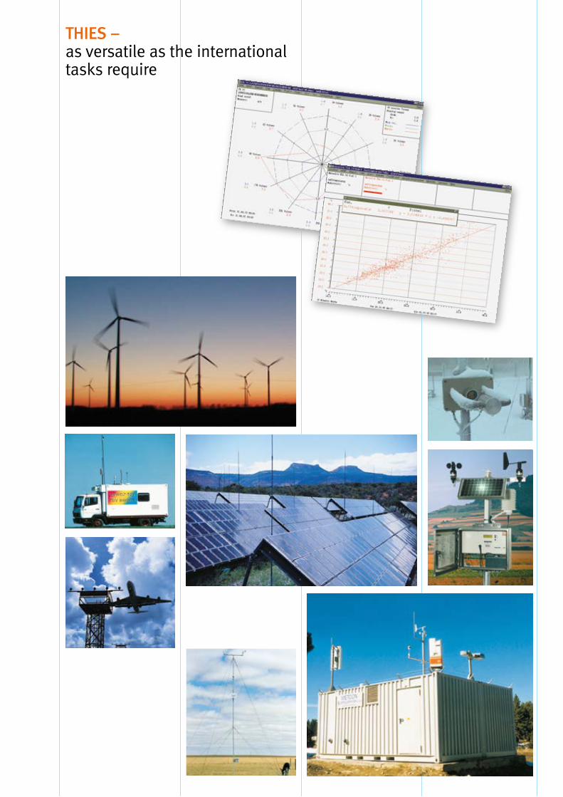
THIES – as versatile as the international tasks require

0101
29/0
9/14
–
Alte
rati
ons
rese
rved
–
cov
er p
ictu
re: F
otol
ia.d
e
THIES-CLIMA – WorldwideWeather and Environmental monitoring technology needs a competent partner
ADOLF THIES GMBH & CO KG Meteorology- Environmental TechnologyBox 3536 + 354137025 Göttingen · GermanyPhone +49 (0) 551 7 90 01-0Fax +49 (0) 551 7 90 [email protected]
We have developed a smoothly functioning system of partners and subsidiaries throughout the world to provide expert advice there where you need it.
THIES assumes complete super-vision of the tasks at hand, from project planning to the instal-lation of the system, from staff training to the processing of the measurement results.Should you want to contact one of our foreign partners, please write or call us first in Göttingen. We will provide you with the exact address.
Climatic measurement and intelligent analysis are inter-national tasks. They do not only demand a worldwide cooperation of the responsible authorities, but also a com-prehensive network of sensors and analytical systems.
Information is everything.Please ask for our complete catalogue and product descriptions concerning all questions of weather data acquisition – or attend our internet page:www.thiesclima.com