Embed Size (px)
Citation preview

Naval Research LaboratoryWashington, DC 20375-5320
AD-A279 922 NRL/MR/5710--94-7485
Wind Tunnel Tests of a 42 Inch DiameterSelf-Starting Autogyro Rotor
STEVEN K. TAYMAN
Off-Board Countermeasures BranchTactical Electronic Warfare Division D TIC
ELECTEJUN 0 1994
May 31, 1994
94-16632I II~i 111 11111 I Dliinl~
c C77Approved for public release; distrbution unlimited.

REPORT DOCUMENTATION PAGE Fn PII OMS ft. 0704-0188
Ptdft OP.I •lrd 1w ftd onf@1 eemion w o estim led to wwwu I h" pw resep o, kck~fh ft tm for r*vewWq W*tuctiW. ewd*g sexeg dm ws.ledmrmaq mad mmndanll II dota needed, wad ceaeia wad aevnewing die1c edno kdwetion Swad comments r~erwdaa dhe Iwde tmaem at ma oi eaec of t
lea . beun, Iug eueetlow fr d t burden to WesVton Hemdquewne Sevi•. Directorate for Irdomtien Opeim wfldAporte. 1216 JeffeeOwD Hisaway. Suie 1204. ArWiton. VA 22202-4302. mad to the Office of Maegemeait aid Sudget. Plewwoerk Reduction Peoect 10704-018), Weedinfton. OC 20603.
1. AGENCY USE ONLY (Lmve MBnk) 2. REPORT DATE 3. REPORT TYPE AND DATES COVERED
May 31, 1994 Interim Report 19934. TITLE AND SUBTITLE 5. FUNDING NUMBERS
Wind Tunnel Tests of a 42 Inch Diameter Self-Starting Autogyro Rotor PE - RE7OPIO
6. AUTHOR(S)
Steven K. Tayman
7. PERFORMING ORGANIZATION NAME(S) AND ADDRESS(ES) 8. PERFORMING ORGANIZATIONREPORT NUMBER
Naval Research LaboratoryWashington, DC 20375-5320 NRL/MR/5710-94-7485
S. SPONSORINGJMONITORING AGENCY NAME(S) AND ADDRESS(ES) 10. SPONSORING/MONITORINGAGENCY REPORT NUMBER
Chief of Naval Research800 North Quincy StreetArlington, VA 22217-5660
11. SUPPLEMENTARY NOTES
12a. DISTROUTIONIAVAILABILrIY STATEMENT 12b. DISTRIBUTION CODE
Approved for public release; distribution unlimited.
13. ABSTRACT (AMtxfum 200 wods)
The autogyro is being investigated for potential use u a small unmanned air vehicle for Navy electronic warfare missions. Thispaper presents wind tunnel test results for a 42 inch diameter unpowered rotor with coupling between feathering and flapping thatallows for self-starting from a vertical deseat. Aerodynamic performance is given for several blade pitch angles and angles ofattack.
14. SUBJECT TERMS 15. NUMBER OF PAGES
Autgyro 20Rotor 16. PRICE CODERotay-wing
17. SECWRITY CLASSIFICATION 1S. SECURITY CLASSIFICATION 19. SECURITY CLASSIFICATION 20. LIMITATION OF ABSTRACTOF REPORT OF THIS PAGE OF ABSTRACT
UNCLASSIIED UNCLASSIFIED UNCLASSIFIED UL
NSN 754001-2104HI-00 9twad rm 2ft Vlv. 2-11ftene by ANS Sad 239-18
235.102

Table Of Contents
Page
Introduction 1
Background 1
axperimental Apparatus 2
Autogyro Model And Inutrumentation 3
Test Results And Discussion 3
Conclusion 6
References 7
Nomenclature 8
Figures
Accesion For
NTIS CRA&IDTIC TABUnannounced 0justification --
By-.-Distibution I
Availability Codes
Avail and IorDist Special
'iU

4-1-93WIND TUNL TESTS OF A 42 INCH DIAMETER
SZLF-STARTING AUTOGYRO ROTOR
Steven K. Tayman, Code 5712
INTRODUCTION:
Autogyros show great potential as small unmanned air vehicles
for Navy electronic warfare missions. The rotor provides high lift
at low speeds and the vehicle is very compact when folded. In aneffort to simplify the vehicle, the feasibility of using tailsurfaces for stability and control rather than the conventionalrotor cyclic and collective pitch controls was explored. Without
collective pitch control, the rotor would only self-start at zeroto negative pitch angles which are inefficient for forward flight.'This rotor model wind tunnel test addressed the self-starting issueand the performance of an autogyro rotor operating at low blade
chord Reynolds numbers.Wind tunnel test results are presented for a small two-bladed
autogyro rotor with high coupling between flapping and featheringsuch that when the rotors flap upward they feather to a negative
pitch angle. This type of hinge is comnmonly termed a Delta-3hinge. The purpose of the offset Delta-3 hinge in this
application, is to allow the rotor blades to fold along a fuselageand be self-starting from a vertical free fall with a rotor angleof attack of 90 degrees. The average blade chord Reynolds numbervaried from 150,000 to 219,000. The effect of varying Reynolds
number on aerodynamic performance is presented. The performance for
different blade pitch angles are compared. In addition to self-starting from a vertical free fall, the Delta-3 hinge allowed self-
starting at angles of attack above 10 degrees with blade pitchangles of up to 4 degrees measured at a flap angle of zero.
5AcKGROUND=
The U.S. Navy is interested in the application of smallunmanned autogyros as expendable decoy vehicles launched from a
Mm~tapproved April 6, 1994.1 1

ship and capable of flying at ship-like speeds. An autogyro is
particularly suited to this mission because of its compactness,
simplicity, and slow speed capability. The current autogyro decoy
design concept requires that the vehicle be deployed from a mortar
tube type launcher by a solid rocket motor. In storage, the rotor
hub is at the rear of the fuselage and the blades are folded
forward along the fuselage. The deployment scheme is illustrated
in Fig. 1. At apogee, the rotor blades are released and blown back
from alongside the vehicle's fuselage and assume a large coneing
angle of about 20-30 degrees. The rotor blades due to the Delta-3
hinge will assume a negative pitch angle. The negative pitch angle
will cause the rotor to begin autorotation in the desired direction
of rotation. As the rotor coneing angle decreases with increasing
rotational speed and the resulting centrifugal force, the pitch
angle increases to a small positive angle (0 to 4 degrees). A
positive blade pitch angle is required to achieve the best
performance possible in forward flight.' Transition to forward
flight from the autorotative descent is accomplished by rotating
the body about 90 degrees relative to the mast, unfolding the tail
surfaces, and applying power to the tractor propeller.
XPIDRXMZ AL APPARATUS:
The experiment was conducted in NRL's low speed wind tunnel
facility, the Off Board Testing Platform (OBTP). The closed loop
tunnel has a four foot square test section and is capable of speeds
from 15 to 200 knots. The settling chamber has a honeycomb flow
straightening section followed by 4 screens. The contraction ratio
is 6.8 to 1.The test section has a sting type model support capable of -12
to 30 degrees angle of attack and +/- 30 degrees of yaw. An
internal strain gage balance measures all six forces and moments.
Output from the balance goes through signal conditioners and is
read by a PC based data acquisition system. Other data gathered by
computer includes the stilling chamber pressure, test section
static pressure, total temperature, pitch position, and yaw
2

position.
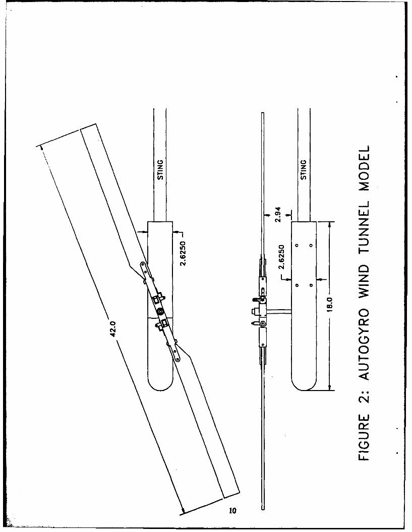
AUTOGYRO MODEL AND INSTRUMENTATION:
The autogyro model has a 42 inch diameter two-bladed rotor
with a 1.75 inch chord (see Fig. 2). The diameter is as large as
wall interference considerations would allow in the 48 inch by 48
inch test section. The rotor blades were made from wooden model
helicopter blades with a 15% thick flat-bottomed airfoil, no
taper, and no twist. The hub has a flapping offset of 1.25 inches
and permitted a maximum coneing angle of approximately 21 degrees.The blade pitch link arms were fixed and mounted off the axis ofthe flapping pin, so as to couple blade feathering with blade
flapping. Two different amounts of coupling were tested by
fabricating different length brackets to which the pitch link armswere attached. The pitch link arm lengths were adjusted to set the
blade pitch angle.
A plywood body with a 2.625 inch square cross section served
as an aerodynamic fairing for the balance. The mast is a 0.375inch diameter steel rod which positions the rotor 4.125 inches
above the center line of the body. The mast was mounted
perpendicular to the body to allow adequate clearance between the
blades and the sting. The rotor was mounted sideways in the
tunnel to allow the rotor to be spun up by hand to help start
autorotation when necessary. Rotor rpm was measured using a halleffect sensor and two magnets mounted on the hub. A small threewire cable powered the sensor and provided the output signal. The
accuracy of the measured rpm was about +/- 10.
TNBT RMSULTS AND DISCUSSION:
Initially, the coupling of feathering with flapping (dO/d )was
set at -0.6, that is for every degree of upward flapping there was
-0.6 degrees of feathering or pitch change. To test whether thismagnitude of coupling was sufficient, the rotor was tested at a 90
degree angle of attack to simulate vertical descent. With the blade
3
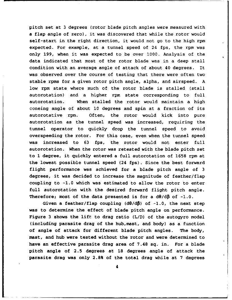
pitch set at 3 degrees (rotor blade pitch angles were measured with
a flap angle of zero), it was discovered that while the rotor would
self-start in the right direction, it would not go to the high rpmexpected. For example, at a tunnel speed of 24 fps, the rpm was
only 199, when it was expected to be over 1000. Analysis of the
data indicated that most of the rotor blade was in a deep stall
condition with an average angle of attack of about 40 degrees. It
was observed over the course of testing that there were often two
stable rpms for a given rotor pitch angle, alpha, and airspeed. A
low rpm state where much of the rotor blade is stalled (stall
autorotation) and a higher rpm state corresponding to full
autorotation. When stalled the rotor would maintain a high
coneing angle of about 10 degrees and spin at a fraction of its
autorotative rpm. Often, the rotor would kick into pure
autorotation as the tunnel speed was increased, requiring the
tunnel operator to quickly drop the tunnel speed to avoid
overspeeding the rotor. For this case, even when the tunnel speed
was increased to 63 fps, the rotor would not enter full
autorotation. When the rotor was retested with the blade pitch set
to 1 degree, it quickly entered a full autorotation of 1658 rpm at
the lowest possible tunnel speed (24 fps). Since the best forward
flight performance was achieved for a blade pitch angle of 3
degrees, it was decided to increase the magnitude of feather/flap
coupling to -1.0 which was estimated to allow the rotor to enter
full autorotation with the desired forward flight pitch angle.
Therefore; most of the data presented is for a dO/df of -1.0.
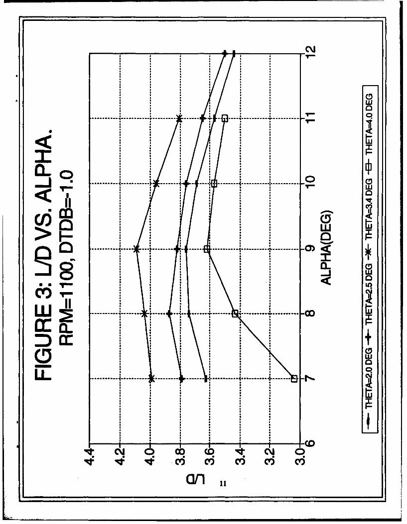
Given a feather/flap coupling (dO/dM) of -1.0, the next step
was to determine the effect of blade pitch angle on performance.
Figure 3 shows the lift to drag ratio (L/D) of the autogyro model
(including parasite drag of the hub,mast, and body) as a function
of angle of attack for different blade pitch angles. The body,
mast, and hub were tested without the rotor and were determined to
have an effective parasite drag area of 7.48 sq. in. For a blade
pitch angle of 2.5 degrees at 18 degrees angle of attack the
parasite drag was only 2.8% of the total drag while at 7 degrees
4
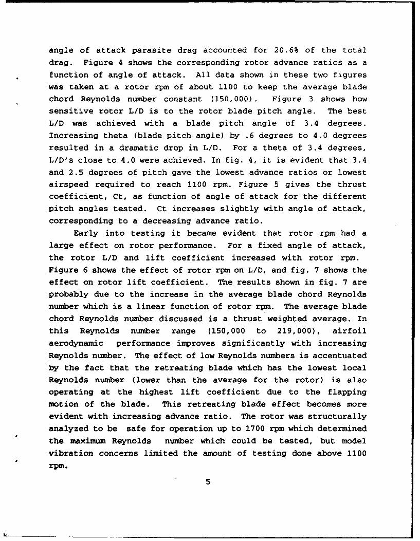
angle of attack parasite drag accounted for 20.6% of the total
drag. Figure 4 shows the corresponding rotor advance ratios as a
function of angle of attack. All data shown in these two figures
was taken at a rotor rpm of about 1100 to keep the average blade
chord Reynolds number constant (150,000). Figure 3 shows howsensitive rotor L/D is to the rotor blade pitch angle. The best
L/D was achieved with a blade pitch angle of 3.4 degrees.
Increasing theta (blade pitch angle) by .6 degrees to 4.0 degrees
resulted in a dramatic drop in L/D. For a theta of 3.4 degrees,
L/D's close to 4.0 were achieved. In fig. 4, it is evident that 3.4
and 2.5 degrees of pitch gave the lowest advance ratios or lowestairspeed required to reach 1100 rpm. Figure 5 gives the thrust
coefficient, Ct, as function of angle of attack for the different
pitch angles tested. Ct increases slightly with angle of attack,
corresponding to a decreasing advance ratio.
Early into testing it became evident that rotor rpm had alarge effect on rotor performance. For a fixed angle of attack,
the rotor L/D and lift coefficient increased with rotor rpm.Figure 6 shows the effect of rotor rpm on L/D, and fig. 7 shows the
effect on rotor lift coefficient. The results shown in fig. 7 are
probably due to the increase in the average blade chord Reynolds
number which is a linear function of rotor rpm. The average blade
chord Reynolds number discussed is a thrust weighted average. In
this Reynolds number range (150,000 to 219,000), airfoil
aerodynamic performance improves significantly with increasing
Reynolds number. The effect of low Reynolds numbers is accentuated
by the fact that the retreating blade which has the lowest local
Reynolds number (lower than the average for the rotor) is alsooperating at the highest lift coefficient due to the flapping
motion of the blade. This retreating blade effect becomes more
evident with increasing advance ratio. The rotor was structurally
analyzed to be safe for operation up to 1700 rpm which determined
the maximum Reynolds number which could be tested, but model
vibration concerns limited the amount of testing done above 1100
rpm.
5

The rotor with a pitch angle of 2.5 degrees was tested at 90
degrees angle of attack to verify that the increased feather/flap
coupling was sufficient to cause the rotor to self-start and enter
full autorotation in a vertical descent. The tunnel was run at its
lowest possible speed, about 24 fps, and the rotor quickly spun upto 1680 rpm. Unfortunately in the closed test section it was not
possible to take meaningful vertical descent performance data due
to wall effects. For example, the dynamic pressure without the
rotor was 0.67 psf, and the rotor generated 11.8 lbs of drag with
a disk area of 9.62 square feet (60% of the tunnel cross-section).
Ignoring wall effects the calculated effective CD for the rotor was
1.83 while the expected value was 1.2.2 Nevertheless, the test did
verify the effectiveness of the feather/flap coupling with respect
to autorotation self-starting.
The aerodynamic power required to fly is a very important
consideration for the application of the autogyro as a decoy
vehicle; especially if electric propulsion is to be used. Because
of the relatively poor energy density of available batteries it is
critical to keep the power requirements to a minimum, otherwise,
the decoy will not have enough flight duration to be effective.
Figure 8 shows the aerodynamic power (drag times velocity)normalized for a lift of 4.5 lbs as a function of angle of attack.
For this model, with its fairly low chord Reynolds number, the
decrease in airspeed required to generate 4.5 lbs of lift withincreasing angle of attack more than offsets the decrease in L/D.
Therefore; the optimum flight condition with respect to power
required occurs at the very high angle of attack of 16 degrees.
The optimum angle of attack for an actual full scale decoy vehicle
would probably be closer to 10 degrees because the small decrease
in power above 10 degrees would not justify the increase inpropeller diameter and gear drive ratio required to attain the same
propulsive efficiency at the lower airspeed.
CONCLUSION:This experiment successfully demonstrated the use of
6
feather/flap coupling to allow a rotor with a positive pitch angle
at a small coneing angle (2-3 degrees) to automatically enter
autorotation at an angle of attack of 90 degrees. From this
experiment, it was determined that a feather/flap coupling of -1.0
with a maximum coneing angle of 21 degrees is sufficient to allow
the rotor to enter full autorotation starting from a vertical
descent with rotors stopped. If for the decoy vehicle design, the
rotors begin autorotation at the launch apogee, the high initial
airspeed (around 150 fps) should accelerate the rotors to flight
rpm (around 900) in a few seconds. The effect of the Delta-3 hinge
on forward flight performance was to improve L/D slightly by
reducing the rotor flap back angle. The improvement in L/D was
offset somewhat by a decrease in rotor lift coefficient.
The rotor's performance in forward flight and the effect of
the average blade chord Reynolds number were measured. For example,
a change in average blade chord Reynolds number from 150,000 to
219,000, increased the L/D from 3.82 to 4.13 and increased rotor CL
from 0.178 to 0.216. Planned autogyro decoys will probably
operate with an average blade chord Reynolds number of over 300, 000
which should result in superior performance compared to this model.
Future autogyro models may be designed to allow operation at up to
2700 rpm which will bring the average blade chord Reynolds number
up to this range. Additionally, airfoils optimized for operation
at these low blade chord Reynolds numbers could be used in the
rotor blade design to improve rotor performance.
References:
'Wheatley, J. B., and Bioletti, C., "Wind-Tunnel Tests Of 10-Foot-
Diameter Autogiro Rotors", NACA Report No. 552, 1935.2Gessow, A., and Myers G. C., Aerodynamics ofthe Helicopter, Frederick
Ungar Publishing Co., NY, 1967.
7
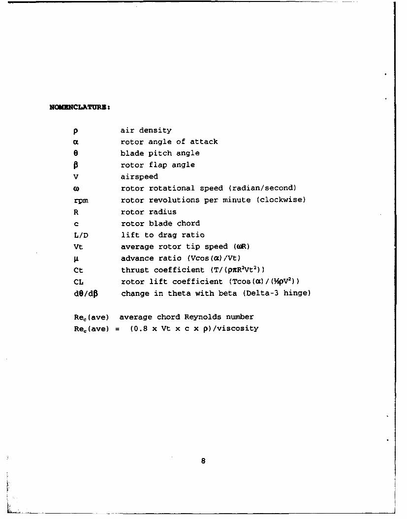
NOMUNCLATURB:
p air density
C rotor angle of attack
0 blade pitch angle
0 rotor flap angle
V airspeed
(0 rotor rotational speed (radian/second)
rpm rotor revolutions per minute (clockwise)
R rotor radius
c rotor blade chord
L/D lift to drag ratio
Vt average rotor tip speed (R)
A advance ratio (Vcos(a)/Vt)
Ct thrust coefficient (T/(pER2Vt 2 ))
CL rotor lift coefficient (Tcos(a)/(MpV2 ))
dO/dP change in theta with beta (Delta-3 hinge)
Re,(ave) average chord Reynolds number
Re,(ave) = (0.8 x Vt x c x p)/viscosity
8

Ls..z L
0-
z 0
V) 0) - 0
LAJm> 0) 0 L Z
CL 0
0 0o 0 0
cxj
LUJ
0C-)LUJ
00
Z 0
Lii
0 00) 0
0 <00
00 WL*L 0 0 W
w 0
0 9
-LJ
0
L_.Lfl f0
zz
0 0
too
0 - N
z
0V 0
0
e4,
a i,i
F-
10
* S a S a* a S a a a* a a a a a* a a a a a
a a a a a a a* a a a a aa a a a a aa a a a a a
* a a a a a* a a a a
* a a a a a* a a a a a w* a a a a a
* a a a a* �. .
a a a a a Ia a a a a aa a a a a aa a a a a a* a a a aa a a a a4 : * a a a aa a a a a a
* a a a a aI * a a a a a______ a a a a a aI. a a a a a a
* a a a a aa a a a a a IJI - Lii0
El a a aEl a a a
* a a a* a a a* a a adim
* a a a a* a a a Ill _a a a a -- ____* a a aa a a a* a a a a a* S a a a a0 a.................................................................................a a a a* a a a a ** a a a a Ia a a a a aa a a a a aa a a a a a* S a a a a 0..a a a a a a* a a a a aa a a a a a w* a a a a a* a a a a a a 0
_____ a a a a a aU a a a a a a* a a a a a* ft a a a aa a a a a aa a a a a aa a a a a aa a a a a aa a a a a aIi a a a a a a* a a a a aElI * a a a.............a aa a a a a a..............................................................................- a -a.
-� ft S a a aa a a a a Ua a a a a aa a a a a aa a a a a aa a a a a a
a a a a aa a a a a i$.a a a a aa a a a a
a a a a a aa a a a a aa a a a a 0a a a aa a a a a Wa a a a aa a a a a 0* a a aa a a a
................ 4.......4........�a a a a a aa a a a a a* ft a a a aa a a a a aa a a a a aa a a a a a* a a a a aa a a a a a* a a a a aa a a a a aa a a a a aa a a a a aa a a a a a
a a a a a a* a a a a a a e* a a a a a* a a a a fta a a a
* * a aa a a a__* see__:**__
�0CO�D q�J. 0c'S
01111

LU
S........ ........ F .......... . !.................... &................... 0 )
* S
0 ---
0
L .".. ... ... ...... ... . .....--- -------"
C5 ,,,d
*' i
(ouivu 3oNvAav) nvy12
S S S

I. Y- - _________ C\j
A 0SLU
S.......L - ..... • aE........ i ......... . ...... ..... .............. . ""
........... ... ....... ..... ...... ......... ... .... ............ .
LLO i EIIm i I ' ÷1
......... 0 .,.,
.-,-........... .... .e.... .. ........... r.,,
.m NI S 3
ii _C/' I
>1- S1_
U . . S S S

a a
lo
a a
W e
..................... ............. T------------ .. ... ............
a an
14
i [w

* a * a* a a a* * a a* a a aa a a a
V a a a a* a a a* a a a* a a a* a a a* a a a* a a a* a a a
A a a a a* a a a* a a a
a a a a* a a aSa a a a* a a a
- � J�* a a a* a a aa a a aDi.... * a a a 1-* a a a* a a a
a a a a* a a a
III a a a a_________ a a a a
a a a a* a a a* a a a* a a a* a a a* a a aa a a aa a a a* a a aa a a
------------------------------------------------------------------------------------------------------------ J* a a* a a a ___* a a aa a a aa a a a* a a a* a a aa a a a* a a aa a a aa a a aa a V aa a a aa a a aQOin * a a a* a a a* a a-J * a a* a a aa a a aa a V aa a a a
Sa--------------------a a a* a a a0 * a a a* a a a* a V a
a a a acEO a a a a* a a a* a a a* a S a%m�W * a a a* a a aa a S aa a a aa a S S-Jo a a a aa a aa a a a* a a a* a a aOLO a a a aa a a aa a a a
*-------------------------------a a a a* a a aS a a a* a a a* a a aa a a aa a S aa a a aa a a a* a a a
a:a a
* a
a U
m a
LL
I I ic�J C�J 0) COc'J c'J 'N- 'N-6 o 6 6 6
(uo±ou)io15

.i, . . . . . . . . . . . . . . . . . •... 4 - .. . . . . . . . . . . . . . . - - - - - - - - - - - - -
.......... .......... S ........... ....... .......... ........... ........... ............ O
* al
ww
........ ...... a....
............................. --------- ......
a .L . . . . . . . . . . . . .... .... .... -- - - - - -- - - - - -
QC4
a 0
(00'A) U3M1d OH3V
16
*' a aaa