Embed Size (px)
Citation preview

Journal o f lndustrial Aerodynamics, 5(1980) 357--372 357 © Elsevier Scientific Publishing Company, Amsterdam -- Printed in The Netherlands
WIND-TURBINE AERODYNAMICS
R.E. WILSON
Oregon State University, Corvallis, Oregon, 97331 (U.S.A.)
Summary
The aerodynamics of wind turbines is reviewed starting with effects of lift and drag on translating devices and proceeding through the performance aerodynamics of the horizontal- axis and vertical-axis machines currently in service. Horizontal-axis rotor aerodynamics is outlined and the performance limits are presented along with key assumptions and problem areas. The Darrieus rotor multiple streamtube analysis is developed and compared with fixed and free wake analyses for an idealized case.
I. In troduct ion
The energy in the wind is in the form of kinetic energy, 1/2 p V:~ where V~ is the wind speed. The kinetic energy flux through an area A perpendicular to the wind is rn 1/2V2 ® or 1/2pAV3~. A wind-power machine may extract as much as 16/27 of this kinetic energy. However in practice, aerodynamic, mechanical and electrical losses reduce the amount of power which can be obtained so that the peak power ou tpu t is about s /27pAV3 ~ . Expressing the area in m 2 and the wind speed in m/s the corresponding power ou tpu t is 1.134 × 10⁻⁴AV3~ kW. This relationship expresses the importance of siting in wind power as improved machine aerodynamic performance is no match for the V3~ dependence upon wind speed.
The cost of electricity is the single most significant parameter by which the effectiveness of a wind turbine can be gaged. In determination of cost, a simple relation is used
(initial cost) fixed charge rate + (O&M) ¢/kW h = (1.1)
(annual kW h) (availability factor)
Here (O&M) represents the annual operation and maintenance costs. Wind- turbine performance deals with the annual energy product ion and is intimately related to the site wind characteristics as well as the machine characteristics. Since wind turbines are no t usually designed for specific sites, wind character- istics are expressed for design purposes in terms of a single parameter, the mean wind speed. The NASA/Lewis wind speed distribution relation used in the USA is such a single parameter relation.

358
Annual wind energy product ion is evaluated by integrating the power with respect to time. Letting H be the time in hours and using the power coefficient C_~ = (power)/(l/2pA Ira ) the annual energy product ion is given by
8760
annual k W h = 1/2pA f CvsV ~ dH (1.2) 0
Here Cps is the system power coefficient which includes transmission and generator efficiencies. Typical transmission and generator losses are of the order of 12% at rated power and a greater percentage loss occurs during partial load operation. The rotor performance is determined from consideration of the action of lift and drag forces on the blades.
The most simple form of wind machine is the device that moves in a straight line under action of the wind. The direction of mot ion determines the type of force experienced by the device; whether it is primarily subject to lift or to drag. Not only are translating lift-driven and drag-driven devices of historical interest but they may also be illustrative in examining various rotary machines since the translation can be considered as an instantaneous blade element of a rotating machine.
First, consider a device to be driven by drag. For such a device the power extracted is equal to the do t product of the drag force and the translation velocity. The power, P, is found to be proport ional to (V®--v)2~, where v is the translational velocity. The translational velocity, p, must lie between zero and the wind velocity, V... Further analysis shows that the maximum power is obtained when ~ = V®/3 so it may be seen that the translational speed does little to increase the power. In fact above a speed of V®/3 increasing the translator speed decreases available power. Drag devices always move slower than the wind and their mot ion detracts rather than enhances the power extraction.
By contrast, lift devices do much better. In simplest form, the lifting translator consists of an aerodynamic body moving perpendicular to the wind. Since lift is always accompanied by drag we must also include drag to obtain an accurate evaluation of lift-driven wind-power machines. The direction of the lift and drag forces are found to depend upon the relative magnitudes of the wind speed V® and the translation speed v. At low values of v/V,., the power extracted from a lift-driven device is proport ional to V 2 . ~ while at high speeds the power varies as ~2[V® - u/El. In both cases, the speed of trans- lation acts to increase the power extraction. The lift-driven device delivers its maximum power at a speed ratio v/V.. = 2E/3 where E is the lift-to-drag ratio of the translator. A comparison of the relative efficiencies of lift- and drag- driven devices may be made. The ratio of power developed by a lift device to that developed by a drag-driven device is approximately E 2. That is, the lift device develops E 2 times that power of a drag device, where E is the lift-to- drag ratio of the lift device. Since this ratio may easily be over ten the lift device can readily produce 100 times the ou tpu t of a drag device of equal area.

359
Of course, sailors have long known they can reach higher speeds moving across the wind rather than moving with the wind. The maximum power for a lift device is achieved when the angle between the translator velocity and the wind is, for usual values of the LID ratio, within 3 ° of moving perpendicular to the wind.
With the superiority of the lift-driven devices established as well as the fact that maximum power is obtained when the device is moving perpendicular to the wind, the concept of placing lifting surfaces on a rotating machine is seen to be an obvious method of deployment. The familiar Dutch Windmill is an adaptation of the sail to a rotating machine which was accomplished during the 1400's.
II. Actuator disk
The starting point in wind-turbine analysis lies in the control-volume ap- proach contained in the actuator-disk concept originated by Rankine and ex- tended by the Froudes for marine propellers. Figure 1 shows a stream tube with an actuator disk representing the wind turbine. The air being decelerated from approach speed V~ to velocity u at the disk and then to u l well down- stream of the disk. Application of momentum and energy relationships for simple axial flow having no tangential component, leads to the relationship
u = 1/2(V~, + ul) (2.1)
Thus half the total velocity decrease ~h(V~ - u~) occurs upstream of the disk and half downstream. This retardation is expressed in the form of an axial induction factor a, such that u = (1 - a)V~ or a = I - ( u / V ~ ) . Hence u~ = V® (1 - 2a) and therefore a has a maximum value of lh when ul = 0.
V.
]
] Fig. 1. Wind-turbine streamtube.
360
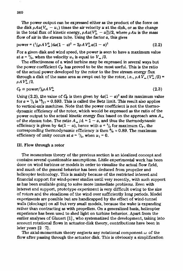
The power ou tpu t can be expressed either as the product of the force on the disk pAu(Vo, - ul) times the air velocity u at the disk, or as the change in the total flux of kinetic energy, pAu(V2~ - u~)/2, where p A u is the mass f low of air in the stream tube. Using the factor a, this gives
power = (I/2pA V3~ )4a(1 - a) 2 = 2pA V3~a(1 - a) 2 (2.2)
For a given disk and wind speed, the power is seen to have a maximum value at a = 1/3, when the velocity u l is equal to V . / 3 .
The effectiveness of a wind turbine may be expressed in several ways bu t the power coefficient Cp has proved to be the most useful. This is the ratio of the actual power developed by the rotor to the free stream energy flux through a disk of the same area as swept out by the rotor, i.e., pAV,~ (V2o./2) = pA V3® /2.
Cp - power/1/~oA V3~ (2.3)
Using {2.2}, the value of Cp is then given by 4a(1 - a) 2 and its maximum value for a = 1/3 is 1~[27 = 0.593. This is called the Betz limit. This result also applies to vertical-axis machines. Note that the power coefficient is not the thermo- dynamic efficiency of the rotor, which would be expressed as the ratio of the power ou tpu t to the actual kinetic energy flux based on the approach area A~ of the stream tube. The ratio A ~ / A -- 1 - a, and thus the thermodynamic efficiency is given by 4a(1 - a), hence with a = 1/3 for maximum Cp, the corresponding thermodynamic efficiency is then 8/9 -- 0.89. The maximum efficiency of uni ty occurs at a = 1/2, when u ~ = 0.
III. F low through a ro tor
The momen tum theory of the previous section is an idealized concept and contains several questionable assumptions. Little experimental work has been done on wind turbines or models in order to visualize the actual f low field, and much of the general behavior has been deduced from propeller and helicopter technology. This is mainly because of the restricted interest and financial support for wind-power studies until very recently, with such support as has been available going to solve more immediate problems. Even with interest and support , p ro to type experiment is very difficult owing to the size of rotors and the steadiness of the wind over sufficiently long periods. Model experiments are possible but are handicapped by the effect of wind-tunnel walls (blockage) on all but very small models, because the wake is expanding rather than contracting as with propellers. On a generalized basis, helicopter experience has been used to shed light on turbine behavior. Apart from the earlier analyses of Glauert [1], who systematized the development, taking into account rotational flows in actuator-disk theory, contributions have been in later years [2--7].
The axial-momentum theory neglects any rotational component co of the flow after passing through the actuator disk. This is obviously a simplification

361
and its effect must be examined. This was done by Glauert following the original analysis for propellers of Joukowski and has been recapitulated in ref. [2]. The addition of a vortex component must reduce the torque and power given to the disk because it introduces rotational kinetic energy to the fluid passing through the disk. It is thus discontinuous at the disk and also is opposite to the disk rotation. It can be shown that for constant angular momentum in the wake flow (irrotational vortex, ¢or 2 = constant) then
a = 1/2b{1 - [52(1 - a ) / 4 X 2 ( b - - a ) ] } (3.1)
where b is the wake axial induction factor, i.e., b = 1 - u l / V ~ . ; X is the tip speed ratio, ~ R / V , . = U / V , , with ~2 the rotor angular velocity, R the rotor radius, and U the rotor tip speed equal to ~2R.
Figure 2 presents a plot of the relationship (3.1) and it is seen that for the ideal actuator disk with X = =, then b = 2a exactly. For X > 2 then b is little different from 2a, but rapidly departs from this value for X < 1. The second term within the brackets in (3.1) is usually small and if b is replaced therein by its approximate value from the axial analysis, 2a, then
a : 1/2b {1 - [a(1 - a ) / X 2] }
The power coefficient with a rotational component is found to be
Cp = b2(1 - a)2/(b - a)
(3.2)
(3.3)
' °[ , ,X , o.k , ~ 06
~s'l' ' O.4
= 0.25/
0 0.1 0.2 0,5 0,4
V®-U ( : t = ~
v . Fig. 2. Effect of tip-speed ratio on induction factors.
i °
V® I ~ / ~ u ~ u i I'
i l 0.5

362
and with b -~ 2a this reduces to
Cp = 4a(1 - a) 2 (3.4)
again the exact relationship for the axial theory. The assumption of the free vortex condition, w r 2 = constant, across the wake becomes untenable near the axis and the free vortex can be replaced with a Rankine vortex having a finite value for Wma x . This is shown in Fig. 3 as CPm=~ vs. ~2R/V®, with values of ¢Om~ = oo, ~2, and ~2/2. This gives an indication that Cpm= x = 16/27 is approached quite closely for ~2R/Vo, greater than about 2, but decreases rapidly for low-speed rotors. For a given power, low values of X imply high torque and the previous analysis shows that this also yields lower values of C~.
g
0.6
0.5
0.4
0.3
0.2
O.I
i ,~iJ u A & =
Vf
WAKE R O T A T I O N A L V E L O C I T Y D ISTRIBUTION
T I | ! I 0 I 2 3 4
V=
Fig. 3. M a x i m u m p o w e r coe f f i c i en t versus t ip-speed ra t io for a r o t o r w i t h R a n k i n e vo r t ex wake.
This is the effect of higher wake rotational energy due to higher torque. But high-torque turbines obviously have bet ter starting characteristics than those with low torque, i.e., they can overcome starting resistance and produce useful power at lower values of wind velocity. Thus a basically more efficient wind turbine will yield reduced energy at minimum wind speeds. The parameter X = U / V . is a very important one in wind-turbine performance, as is its inverse

363
V=/~2R in propeller performance. It is a dimensionless kinematic parameter and is related to the helix angle of the shed vorticity. It contains the three most important variables of turbine design and analysis; the wind speed, the rotor size, and the rotor rpm. It is used as a parameter against which the effect of aerodynamic variables as well as overall performance parameters such as power output , Cp, etc. may be expressed.
The actuator-disk analysis is an idealized concept and efforts continue to be made to refine it to provide more exact answers. It does seem important that there should be a firm standard representing maximum performance capability against which to judge actual wind-turbine behavior. The simple axial-disk analysis leads to the result that the induction factor a cannot be greater than 0.5 as this yields zero downstream velocity. However, increasing thrust coefficient values are obtained for a > 0.5.
Following on the early work of Glauert and others on flow regimes in pro- pellers (and to some extent with wind turbines), Wilson and Lissaman [2] , Wilson et al. [4] and Stoddard [6] have enlarged autogyro and helicopter rotor experience. It is possible by using the momen tum theory alone to analyze several f low patterns for a propeller-like rotor and to gain an understanding of general behavior under a variety of circumstances. There are three overall f low states for a rotor which can be distinguished, each for a range of the induction factor a. These are shown diagrammatically in Fig. 4. For a < 0 (i.e., negative values), the rotor is acting as a propeller accelerating the flow, with thrust opposing flow and requiring power to be added. The thrust and power coefficients CT and C~ are then negative (CT = thrust/l/2pAV2® ). The second regime has two subdivisions, one for 0 < a < 0.5, and one for 0.5 < a < 1.0.
/
1,5 / / / / "(~EMPIRICAL / t / (GLAUERT) /
/
t CT 0 -~ -0.5 .5 1.0 -0.5 / 0
-1.5- iV. , Iv= . Iv. Iv. iv.
ROTORsTO~TERATING PROPELLOR'~---- WlNOMILL ._..L.Tuee~ENI WlNOMILL "I"LvoRTEX"LPROPELLORmN6 I BRAKE
Fig. 4. Rotor flow states.

364
Both are for decelerating flow, with C,r and C~ positive, and hence power is extracted from the flow. This is then the "windmil l" state, with the former subdivision termed the (normal) "windmill brake state", with Cr a maximum at a = 0.5 and Cp a maximum at a = 1/3. At a > 0.5, the wake velocity is zero, streamlines cease to exist, and the regime is incompatible with the simple m o m e n t u m assumptions. For 0.5 < a < 1.0, the simple theory would require flow reversal in the far wake and zero velocity somewhere between disk and infinity. It is therefore necessary to look to observed behavior, since the rotor continues to operate in this anomalous state. It is called the " turbulent wake state", characterized by large recirculating flows and high turbulence. Values of CT increase in this state, which is likened to that of a solid disk perpendicular to flow, with analogous downstream reverse flow and turbulence, and a wind- wise force coefficient of 1.2 and greater, which is actually observed. For a > 1, the ro tor enters the propeller brake state, with power being added to the flow to create downwind thrust, corresponding to reversing propeller thrust on landing. For values of a not greatly over unity, the flow regime is called the vortex ring state, experienced by helicopter rotors during part-power descent. Airplane propellers pass through this state to that of their brake state with reversing thrust, a > 1.
Wind turbines will then normally operate in the region of 0 <a < 0.5, but when a rotor operates at tip-speed ratios appreciably above the design value, then the tips may be driven into the vortex ring state.
In the region a > 0.5 it may be noted that there is a considerable difference in the force coefficient CT between the Glauert relation and the momen tum relation. When the momen tum relation, CT = 4a(1 -- a) is used locally in strip theory models, the predicted forces and performance differ significantly from test results for certain cases. Recently, as a result of comparing test results and theory, Dugundji et al. have shown that the Glauert relation gives better cor- relation with experiment than the momen tum relation [8].
IV. Aerodynamic analysis of rotors - p r o p e l l e r type
The global approach via the actuator-disk model supplies the basic analysis, but it is necessary to introduce aerodynamic theory to design a rotor to yield a known performance in terms of force, torque and power, or alternatively to determine these elements for a given rotor. The origin of such analysis lies in nineteenth-century work on marine propellers and it was greatly extended by the advent o f aeronautics and the application of wing theory to propeller design, which in turn serve as the starting point for wind turbines. It is not the purpose here to examine these analyses in great detail, but again the basic approach is recapitulated to establish the method as it applies to wind turbines and to focus on their particular problems. The model used is that of the "propel ler" type of turbine, quite obviously in view of the history of the analysis, but it is capable of application to any lift type of rotor with some modification, including the Darrieus rotor. Thus, the terminology and geometry used is that of the horizontal-axis airfoil-bladed rotor.

365
Figure 5(a) shows a diagrammatic front view of such a rotor blade, with a blade profile shown at radius r, while Fig. 5(b) shows an enlarged profile section with the relevant velocities and forces. The wind velocity V® is modi- fied at the rotor by the axial induction factor a and the rotor velocity ~2 r is modified by a rotational induction factor a' defined as a' - ¢o/212. The blade
i_ I (o)
d5
v=O-a)
Fig. 5. Airfoil-blade geometry. (a) Front view; (b) profile section.
angle is given by ~, and @ is the angle between the plane of rotation and the relative velocity W. The air flow gives rise to a lift force L and a drag force D whose resultant can be resolved into components of normal force dF n and tangential force dF t perpendicular to and parallel to the plane of rotation, respectively. From the geometry, we have
dFn = L cos @ + D sin ¢ (4.1)
dFt = L sin ¢ - D cos ~ (4.2)
The thrust dT on the number B of blade elements dr of chord c is given by
dT = Bc ' /~p W2C~ dr (4.3)
where C, is the normal force coefficient. Applying the momentum equation to a control volume formed by the annulus containing dr and extending from the free stream to the far wake, this force may be written as
dT= drh(V~ -- u~)
with din = p(2~r dr)u and using the momentum relationships one obtains
dT = p(2nr dr) (1 - a ) V . ( 2 a V ~ )= urdrp V2. (CT)loca, (4.4)

366
Equating (4.3) and (4.4) and substituting W sin ~ ffi V~ (1 - a) and ( C T ) ~ = 4a(1 -- a) yields
a/(1 - a) = oC~/(4 sin 2 ~), where o = Bc/21rr (4.5)
Considering only the lift to produce action-at-a-distance forces, then C~ = CL cos ~b, and
a/(1 - a) = aCL cos ~/(4 sin 2 ~) (4.6)
A similar analysis can be made for the torque dQ from the force dF t and this is equated with the angular m o m e n t u m of the air. Using the approximation b = 2a, as before, results in
a'/(1 + a') = UCL/(4 cos~) (4.7)
From eqns. (4.1)--4.7), together with previous expressions for torque and power, the elements of rotor blade design can be established. This is the basis of the blade element or strip theory, which assumes that each elementary strip or annulus behaves independent ly of every other strip. Glauert has developed the analysis to show the opt imum variation of the angle ~ along the blade and the number and shape of the blades. This gives rise to the relationship of solidity aCT. and velocity ratio ~ R / V , . , where R is the blade-tip radius, and the characteristic form of fast-running wind turbines resembling propellers and of slow-running turbines with a large number of blades with large blade angles. References [2] and [4] demonstrate an iteration procedure for these basic relationships by assuming values of a and a', then calculating ¢, ~, and the force coefficients from airfoil data and substituting back in (4.6) and (4.7) until agreement with the assumed values is obtained.
The next step in rotor analysis is the introduction of vortex theory, that is, the discontinuity introduced by the rotor into the undisturbed wind is represented by a vortex sheet or tube behind the rotor. This has been used in the development of propeller theory for many years but its application to turbines would seem to require replacement of the rigid wake vortex of a propeller by more-flexible models. Useful summary presentations are given in [2, 4, 5, 9].
An illustration of the vortex flow model is shown in Fig. 6, with a system of bound vortices along the rotor blades which produce the lift on the blade and free vortices at the rotor tips which produce the induced velocity components. This yields a vortex tube of increasing radius downstream to- gether with a central vortex to fulfill the Helmholtz vortex cont inui ty laws. A high tip-speed ratio X or a large number of blades result in a " t ighter" helix, passing in the limit to a continuous bounding vortex system for an infinite number of blades. The expanding nature of the wake vortex leads to some relief f rom difficulties which occur with the contracting wake of the propeller, e.g., trailing vortex-blade interaction at low advance ratios.
Foley [10] has presented a comparison of classical wake analyses and dis- to t ted wake analysis for a wind turbine and concluded that the added

v¢,, - - - - *
Fig. 6. Vortex-flow model for a propeller-type wind turbine.
367
complexi ty of employing a distorted-wake computer model is probably not warranted for wind turbine analysis because:
1. The tip vortices are posit ioned sufficiently behind the turbine to make the distortion of each point on the tip vortex small, relative to its distance to the wind-turbine blades.
2. The distortions are in a direction away from the wind turbine so that the tip vortices do no t pass directly under the blades. This is opposite to the tip- vortex distortions for a powered propeller where the tip vortex is distorted toward the blade and can lead to large aerodynamic interference effects when the tip vortex of one blade passes close to the following blade.
Wilson et al. [4] discuss the aerodynamics of opt imum-performance wind turbines as calculated by the Goldstein method. Opt imum wind turbines have also been examined by Rohrbach and Worobel [9]. It was seen earlier that the power coefficient Cp and the tip-speed ratio X were primary parameters for design and performance and can be given in terms of the rotor geometry, that is, the number of blades, chord distribution, twist and airfoil section as expressed by the lift/drag ratio L/D. Some of the results are shown in Figs. 7 and 8. Figure 7 shows the effect of number of blades B for L / D = ~o (no drag), with Cp increasing with B and X, with significant but no t major difference for the former. Figure 8 shows the strong adverse effect of decreasing L I D ratio, particularly the decreasing power coefficient with X for low values of L/D.
V. Aerodynamic analysis of Darrieus rotors
The obvious difference between cross-wind rotors and the wind-axis type is that there is a continuously varying local wind as a blade rotates from "up- wind" to " d o w n w i n d " or "leeward". The previous general aerodynamic ap- proach via wake-momentum analysis and blade-element theory can be followed bu t there are differences in analysis according to the assumptions made and the degree of complexi ty of solution. A quasi-steady condit ion is usually assumed and effects of the upwind blade influence on the blade in downwind

368
Cp
0 . 6 -
0.5
0.4
03
tl 0.2 I
0.1
I 0
I I G L ~ d U E R T I D E A L I I I I _
'1
L / D = o ~
0.6
O.5
0.4
Cp 0.3
0.2
o.i
I I I I I I I I 4 8 12 16 20 0
TIP SPEED RATIO, R,(),/V,=o
Fig. 7. Ef fec t o f number o f blades on power coeff ic ient .
Fig. 8. Ef fec t o f L/D ratio on power coeff ic ient .
~ G L , ~ U E R r / D E ' A L I J I I
L / D = o o
4 8 12 16 2( TIP SPEED RATIO, R,C/,/V~o
position is neglected. Figure 9 shows a diagrammatic plan view of a Darrieus with notation used in the succeeding discussion.
Templin's analysis [11] is the earliest, as the work of the NRC of Canada beginning in the mid 1960's heralded the present interest in the Darrieus concept. It is simple and straightforward and results in good agreement with the available test data. It treats the f low as a single streamtube with the induced velocity constant across the rotor, which allows a closed solution, but which limits its use to lightly loaded blades and circumstances in which there is no
voo
/ i1
\ / \ /
\ /
"~-- .-,_L J
__ CROSSWlNO
- - FORCE
WlNDWlSE
FORCE
Fig. 9. F l o w geometry o f Darrieus rotor.

369
significant variation of wind velocity across the flow area. The analysis includes aerodynamic drag of the blades and it shows that performance is sensitive to drag, particularly at high values of X.
Other analyses [2, 12.---15] adopt the multiple-streamtube concept, for which an iteration procedure is required, as the ratio of wind speed u at the rotor to the freestream velocity V . is not constant and must be obtained by matching of momen tum and blade-element relationships. An analysis by Wilson and Lissaman using a model with straight blades parallel to the axis, inviscid flow, and a lift coefficient CL = 2~ sin a demonstrates very simply some of the essential behavior of the Darrieus rotor. The local induction factor a = 1 -- u / V ~ is given by a = aXisin 0 I, where a = solidity = B c / 2 R , with B equal to the number of blades, c the chord, R the rotor radius, and X = ~ 2 R / V ~ . Theta is the blade angular position, Fig. 9, defined with 0 = 0 at 3 o'clock position.
The time averaged power coefficient is given by
Cp = 21¢oX[1/2 - ( 8 / 3 n ) o X + 3/ao2X2]
This yields a maximum value of Cp = 0.554 when amax = 0.401, indicating a slightly lower value than the 0.593 for the simple actuator-disc model. Also, the maximum angle of attack occurs near 0 = ~/2 and tan a = (1 -- a ) / X = 1 / X - B c / 2 R . Thus if amax is the stalling angle = 14 °, then the starting value of X ~- 4/(1 + 2 B c / R ) . This means that for typical values of B, c, and R, the minimum starting value of X will be the order of 2--3. This first approximation is borne out in practice and the Darrieus rotor needs to have a starting device of some sort. If drag is considered for this model, it can be shown that the reduction in power coefficient is given approximately by
ACp = --CD ( B c / 2 R ) X 3
An analysis of a curved rotor is also carried out by introducing the local angle between the blade tangent and the axis of rotat ion and integrating for a given geometry. A circular arc rotor shape yields Ce = 0.536 at am~x = 0.461.
Holme [15] has conducted an elaborate analysis for two-dimensional inviscid flow through a straight-bladed VAWT. He takes into account bound vorticity as well as the wake vorticity and uses the Biot-Savart relationship for obtaining the induced velocities from vortex sheets. His results show that the velocity induction effect is such that half the retardation takes place within the turbine itself and hence that blade incidence and aerodynamic loading are much higher on the windward side than on the leeward side. Streamtube analyses do not show these unsymmetrical conditions. A numerical calculation shows tha t for a value of o = 0.2, a maximum Cp of 0.545 at X = 3.54 is obtained. The angle of attack was found to vary from - 1 3 . 5 ° to +8.5 ° . The most complex method of analysis that has been developed for the Darrieus rotor is the free-vortex approach [16] . Using the circle theorem, the airfoil is mapped into the circle plane where the Kut ta condition is satisfied and the strength of the induced center, shed and image vortices are determined. The wake is modeled by discrete, force-free vortices convected downstream with

370
velocity determined by induced velocities from the rest of the system. The method has been checked by comparison with the K~n~n--Sears solution for a plunging fiat plate and the discrete-vortex approach yields excellent agree, ment with the analytical solution.
The forces and the moment on the blade are determined by two independent methods: (1) Integration of the pressure over the airfoil using the unsteady Blasius theorem; and (2) determination of the impulse of the wake vortices.
Agreement between these two approaches to two significant figures is used to argue that a force-free wake exists.
The free-vortex approach stands to yield understanding of the role of un- steady aerodynamics for the Darrieus rotor. Both the unsteady flow and the wake crossing are found to have a significant role in determining the forces on the Darrieus rotor blades. Additionally, the moment is determined by this approach.
The free-vortex approach, however, has several disadvantages. These are: (1) It is quite expensive to use; (2) the effects of stall are not included; (3) only a single, straight-bladed rotor may be treated; and (4) the values for the performance and loads are approached asymptotically. Since the wake never reaches an infinite length, the loads and performance are higher with a finite- length wake than would be obtained with an infinite wake.
The angle of attack history for a rotor going through a cycle is shown in Fig. 10. The agreement between the various methods is good with the exceptiox that the streamtube methods fail to predict the fore and aft angle of attack differences. At a tip speed ratio of 3.54 this fore and aft difference is in the range of 2 to 4 degrees. In an actual rotor, the blades in the upwind position will experience higher than predicted angles of attack when using streamtube methods.
Since the Darrieus rotor uses fixed pitch blades, the operating envelope is uniquely determined by the aerodynamics, that is, the power coefficient versus
16
¢$ 0 I I I I pZ 30 60 90 120 150 h
0 _ 4 ' UJ ..J
-12
FREE VORTEX METHOD - - F I X E D WAKE METHOD . . . . . . MULTIPLE STREAMTUBE
METHOD SINGLE STREAMTUBE
METHOD
1 I I 1 l J 180 ° Zl0 240 270 300 330 360
B L A D E P O S I T I O N , 0 -16 ~
Fig. 10. Angle o f a t t a ck h i s t o r y o f Darr ieus ro to r , c/R = 0.2, X = 3.54.

371
tip-speed ratio curve. During constant rpm operation, the low wind-speed performance is governed by the zero-lift drag coefficient, CD0, while the high wind-speed portion of the envelope is governed by the nature of the blade stalling characteristics. Power coefficient tailoring using the difference in blade angle of attack (possibly employing blade camber) holds the prospect of improving the cost effectiveness by producing an operating envelope of the Darrieus rotor that is similar to the ramp-plateau shaped operating envelope of the horizontal-axis wind turbine.
Notation
a axial induction factor a' angular induction factor A flow area b wake induction factor B number of blades c blade chord CL blade sectional lift coefficient CD blade sectional drag coefficient Cp power coefficient CT thrust coefficient C~ blade local normal force coefficient D section drag force E lift-to-drag ratio of translator device Fn local force normal to plane of rotation Ft local force parallel to plane of rotation L section lift force rh mass flow rate through turbine r local blade radius R rotor tip radius T force in streamwise direction u local axial velocity at rotor U l axial velocity in far wake U rotor tip speed V~ free stream wind speed W local wind speed relative to blade X ratio of rotor tip speed to wind speed
blade angle of attack local blade pitch angle angle of flow relative to rotor plane of rotation
0 Darrieus rotor blade position p fluid density ~2 rotor angular velocity ¢o fluid angular velocity v translator speed o solidity: Bc/2•r, horizontal-axis rotor; Bc/2R, Darrieus rotor

372
Subscripts oo free stream 1 far wake n normal to plane of rotation t tangent to plane of rotation
References
1 H. Glauert, in W.F. Durand (Ed.), Airplane Propellers, Aerodynamic Theory, Vol. 4, Springer, New York (Reprinted, Dover, New York, 1963).
2 R.E. Wilson and P.B.S. Lissaman, Applied aerodynamics of wind power machines, PB 238595, Rep. No. NSF-RA-N-74-113, NTIS, Springfield, Virginia.
3 E.E. Lapin, Theoretical performance of vertical axis wind turbines, ASME Pap. No. 75-WA/Ener-1, 1975.
4 R.E. Wilson, P.B.S. Lissaman and S.N. Walker, Aerodynamic performance of wind turbines, Oregon State Univ., Corvallis. 1976.
5 C. Rohrbach, Experimental and analytical research on the aerodynamics of wind turbines, Mid-term Tech. Rep., June 1--Dec. 31, 1975, COO-2615-76-T-1, United Technology Corp., Windsor Locks, Conn.
6 R.S. Stoddard, Wind Tech., 1(1) (1977) 3--9. 7 U. HUrter, Annu. Rev. Fluid Mech., 9 (1977) 399--419. 8 J. Dugundji, E.E. Larrabee and P.H. Bauer, Experimental investigation of a horizontal
axis wind turbine, Volume V. Wind Energy Conversion ASRL TR-184-11, M.I.T. Dept. of Aeronautics and Astronautics, Cambridge, Mass., 1978.
9 C. Rohrbach and R. Worobel, Performance characteristics of aerodynamically optimum turbines for wind energy generators, Annu. Forum, 31st, Am. Helicopter Soc., Washington, D.C. S-996, 1975.
10 W.M. Foley, From daVinci to the present -- A review of airscrew theory for helicopters, propellers, windmills and engines, AIAA Paper 76-367, July, 1976.
11 R.J. Templin, Aerodynamic performance theory for the NRC vertical-axis wind turbine, Rep. No. LTR-LA-160, N.A.E., 1974.
12 P.N. Shankar, Proc. R. Soc. London. Ser. A, 349 (1976) 35--51. 13 R.J. Muraca, M.V. Stephens and J.R. Dagenhart, Theoretical performance of cross-
wind axis turbines with results for a catenary vertical axis configuration, NASA Tech. Memo. NASA TM X-72662, 1976.
14 J.H. Strickland, The Darrieus turbine: A performance prediction model using multiple streamtubes, SAND 75-0431, Sandia Lab., Albuquerque, New Mexico, 1975.
15 O. Holme, A contribution to the aerodynamic theory of the vertical-axis wind turbine, Proc. Int. Syrup. Wind Energy Syst. BHRA, Cambridge, U.K., Pap. C4, 1976.
16 R.E. Wilson and W.R. McKie, A comparison of aerodynamic analyses for the Darrieus rotor, Proc. Int. Wind Energy System, BHRA, Amsterdam, 1978.