Embed Size (px)
Citation preview

Windfreak Technologies SynthNV PRO API Guide v1.0a Hardware v1.x, Firmware v2.x
© Windfreak Technologies, LLC. 2019. All rights reserved.
_______________________________________________________________________
Windfreak Technologies SynthNV Pro Programming Interface
The SynthNV Pro responds to commands that come in through its USB port. The USB port,
when plugged in and powered will be assigned a COM port by its operating system that will
accept serial commands from your code or from a basic terminal emulator. With Linux and
Windows 10 the drivers are supplied automatically by the OS. If using older versions of
Windows, you will need to install the drivers from the CD or software download.
Communicating with the SynthNV Pro:
First you need to know the COM Port that your computer assigns to your SynthNV Pro. Go to
Device Manager and see what has been assigned. In this case we are using COM12. Yours may
say Teensy in the description. If you have a few COM ports assigned it is a good idea to plug
and unplug the device to know for sure which is which.
Once you know the SynthNV Pro COM port, communicating with it is as simple as:
1) Open the COM port
2) Send a command character (example “f” without quotes)
3) Send data characters (example “1000.0” without quotes)
4) Close the COM port
If you know the cable will not be unplugged, you could leave the COM Port open.

12.5MHz – 6.4GHz Signal Generator plus RF Detector
2 Windfreak Technologies, LLC.
All the legacy COM port settings such as Data bits, Stop bits, etc. are “don’t cares”. It is
important to set baud rate to anything but 1200 baud. All communication will go at full USB
speed no matter what these settings are.
The SynthNV Pro does not accept termination characters such as carriage return or line feed.
This was done to make the USB communication scheme as simple and fast as possible. It is
possible to string together multiple commands. For example, setting frequency and power to
1000.0MHz and 0.0dBm would be formatted like: “f1000.0W0.0” (without the quotes or any
termination characters). Since there are no termination characters it is essential that the
command and data are sent as a packet all at once.
Finally, the SynthNV Pro expects case sensitive characters. It is essential that for any data you
send to the device you convert any number values to their corresponding characters. In other
words, the number 255 has a value that is represented as a single byte value (b11111111), but it
will need to be converted to 3 bytes of characters 2,5, and 5. Programming languages such as
LabVIEW have a native function to do this shown below:
Using a Serial Terminal:
Before beginning your programming project, it might be a good idea to do some communicating
with a 3rd party terminal program to understand how some of the commands work. In Windows,
Windfreak Tech recommends a free program called Termite from www.compuphase.com.
CuteCom is recommended for Linux. Serial USB Terminal is recommended for Android. The
following graphic shows the use and setup of Termite. The only thing to set up is under Setting /
“Transmitted text”. There you will need to set “Append nothing” to transmitted characters. A
Cutecom screen capture follows with the circled portion showing how to remove termination
characters in that program for Linux.

12.5MHz –6.4GHz Signal Generator plus RF Detector
Windfreak Technologies, LLC. 3
At the bottom of the screen is the command and data entry box. Send a “?” to have the SynthNV
Pro respond back with a list of its commands. Try sending a frequency or power command like
already mentioned and watch for the change on your spectrum analyzer. Also try sending
queries like “f?” to have the SynthNV Pro respond with the status of that command variable. All
responses are terminated with a “\n” which is a LF (or New Line) character.

12.5MHz – 6.4GHz Signal Generator plus RF Detector
4 Windfreak Technologies, LLC.

12.5MHz –6.4GHz Signal Generator plus RF Detector
Windfreak Technologies, LLC. 5
After sending a “?” command the SynthNV Pro will respond with a list of its commands
and settings similar to the following list. Click the links below for quick access to further
details on each command.
f) RF Frequency Now (MHz) 1000.00000000
W) RF Power (dBm) 10.300
V) Amp Calibration success? 1
Z) Temperature Comp (0=none, 1=on set, 2=1sec, 3=10sec) 3
w) Read Pwr Detector dBm (burst samples) -49.112
&) RF Detector Mode Inst(0), Av(1), Pk(2) 0
a) VGA DAC Setting (0=min, 4000=max) 2238
~) RF Phase Step (0=minimum, 360.0=maximum) 0.0000
h) RF High(1) or Low(0) Power 1
E) PLL Chip En On(1) or Off(0) 1
U) PLL charge pump current 5
D) REF Doubler On(1) or Off(0) 0
i) Channel spacing (Hz) 10.000
x) Reference (external=0, int 27MHz=1, int 10MHz=2) 1
*) PLL reference frequency (MHz) 27.00000000
l) Sweep lower frequency (MHz) 1000.00000000
u) Sweep upper frequency (MHz) 5000.00000000
s) Sweep step size (MHz/%) 200.00000000
t) Sweep step time (mS) 1.000
[) Sweep amplitude low (dBm) 0.000
]) Sweep amplitude high (dBm) 0.000
^) Sweep direction (up=1 / down=0) 1
X) Sweep type (lin=0 / tab=1 / %=2) 0
r) set reading while sweeping (on=1 / off=0) 0
d) set sweep display (off=0 / freq+amp=1 / only amp=2) 0
m) show maximum then minimum of a sweep (not enabled yet)
g) Sweep run (on=1 / off=0) 0
c) Sweep set continuous mode 0
y) Enable trigger: (0=software, 1=sweep, 2=step, 3=hold all) 0
F) AM step time (uS) 4998
q) AM # of cycle repetitions 65

12.5MHz – 6.4GHz Signal Generator plus RF Detector
6 Windfreak Technologies, LLC.
A) AM Run Continuous (on=1 / off=0) 0
P) Pulse On time (uS) 1
O) Pulse Off time (uS) 10
R) Pulse # of repetitions 10
:) Pulse Invert signal (on=1 / off=0) 0
G) Pulse Run one burst
j) Pulse continuous mode 0
<) FM Frequency (Hz) 500
>) FM Deviation (Hz) 10000
,) FM # of repetitions 100
;) FM Type (sinusoid=0 / chirp=1) 0
/) FM continuous mode 0
b) Speaker Feedback Mode 0
p) Phase lock status (lock=1 / unlock=0) 1
z) Temperature in degrees C 27.750
v) Show version (0=firmware, 1=hardware) 2.01
+) Model Type
-) Serial Number 25
e) Write all settings to eeprom
?) help
Command Definitions:
Set Frequency in MHz (Command f):
The SynthNV Pro frequency is settable between 12.5MHz and 6400.0MHz. The setting is
always in MHz.
fxxxx.xxxxxxx sets frequency to x MHz in 0.1Hz resolution
f? queries frequency setting in 0.1Hz resolution
Set Power in dBm (Command W):
The SynthNV Pro RF power is settable between -60dBm and +20dBm depending on frequency.
With this setting the SynthNV Pro will automatically calibrate itself and set the power as close as
it can get to what is requested.
Wxx.xxx sets RF power to x dBm in 0.001dB resolution
W? queries the RF output power setting in 0.001dB resolution

12.5MHz –6.4GHz Signal Generator plus RF Detector
Windfreak Technologies, LLC. 7
Query for Successful Calibration Completion (Command V):
If the SynthNV Pro can successfully complete its calibration routine upon frequency or
amplitude set, it will set a flag of 1 showing the output should be accurate and leveled.
V queries if there was successful calibration. 1=success, 0=failure
Set Temperature Compensation Method (Command Z):
The SynthNV Pro RF power can be stabilized over temperature. “On set” means that it will only
be adjusted for when frequency or power is set. The 1 second and 10 second setting will also
both be adjusted “on set” as well but also automatically compensate every 1 or 10 seconds
respectively. The default setting is to automatically run the routine every 10 seconds. During
modulation, the temperature compensation routine is put on hold and resumes once modulation is
turned off.
Zx sets the method for temperature compensation (x=0=none, 1=on set, 2=1sec, 3=10sec).
Z? queries the setting for Temperature Compensation
Read Power Detector (Command w):
Measure detected RF power on the RFin connector. The report is in dBm followed by
“/nEOM./n” where “/n” is a line feed termination character. Sending “w” or “w0” or “w1” all
respond with 1 measurement. If requesting more than 1 measurement, the device measures as
fast as it can and each dBm response is followed by “/n” with the end of message designated by
“EOM./n” . The RF detector uses the RF generator frequency setting for its calibration
frequency. Disable the RF generator (“E0”) for maximum dynamic range if not concurrently
using the RF generator.
An example response for a “w5” command is as follows:
“-10.176
-10.176
-10.149
-10.176
-10.176
EOM.”
wx measures RFin power x times
Set RF Detector Mode (Command &):
The RF power detector can asynchronously measure RF power in 1 of 3 modes:
0) (“&0”) The default measurement mode is instantaneous. This mode sets the log detector
to measure with no averaging. Its best for CW signals with similar peak and average
power levels. This mode is calibrated.
1) (“&1”) This mode runs the output of the log detector through an RC (series resistor, shunt
capacitor) low pass filter to achieve some amount of averaging of the incoming signal.
Use this mode for signals with different peak and average powers that vary quickly. The
RC time constant (t=R*C) is 5.6mS. This mode is calibrated.
2) (“&2”) This mode runs the output of the log detector through a series diode, shunt
capacitor to attempt to capture sporadic peak RF events, possibly in conjunction with
using the internal speaker. This mode is experimental and not calibrated due to the diode

12.5MHz – 6.4GHz Signal Generator plus RF Detector
8 Windfreak Technologies, LLC.
voltage drop. There is a bleed-off resistor for the capacitor that has a time constant of
50mS.
&x sets the method for RF detection (x=0=instant, 1=average, 2=peak).
&? queries the setting for RF Detector Mode
Set Raw DAC Value (Command a):
The SynthNV Pro RF power setting can be bypassed and set with a raw VGA DAC value
between 0 and 4000. A setting of 0 is minimal and 4000 would be maximum gain. To use this
function Temperature Compensation must be turned off with “Z0”.
ax sets DAC value for x drive level where x is between 0 and 4000
a? queries the DAC setting
Set Phase Step Value (Command ~):
The SynthNV Pro RF phase can be adjusted. These adjustments are relative adjustments that add
the phase amount to the current phase being generated. There is no way (currently) to know the
absolute phase setting of the SynthNV Pro without external measurement. Every reboot or
frequency change (besides FM) will reset the phase to an arbitrary value.
~xxx.xxx sends a phase increment to the SynthNV Pro in x degrees. (Sending x359.0 will appear
to decrement the phase by 1.0 degrees).
~? Has no real meaning.
Set RF Mute (Command h):
The SynthNV Pro output power can be muted without fully powering down the PLL. The
amount of muting depends on frequency.
hx sets the muting function where x=1=not muted and x=0=muted
h? queries the setting
Set PLL Power On (Command E):
The SynthNV Pro PLL can be powered down for absolute minimum noise on the output
connector. This command enables and disables the PLL and VCO to save energy and can take
20mS to boot up.
Ex sets the enable function where x=1=powered on and x=0=powered off
E? queries the setting
Set PLL Charge Pump Current (Command U):
PLL loop filter bandwidth can be adjusted to a certain degree through the PLL charge pump
current setting. This can affect things like lock time, phase noise and FM quantization noise. In
general, higher values give higher loop filter bandwidths, but the steps are not monotonic. Higher
bandwidths tend to have better phase noise and stepping times, but possibly higher spurs. A
setting of zero should be avoided as the charge pump output is tri-stated and the PLL will not
phase lock.
Ux sets the the charge pump current where x=1 through 15 is allowed
U? queries the setting

12.5MHz –6.4GHz Signal Generator plus RF Detector
Windfreak Technologies, LLC. 9
Reference Frequency (x2) Doubler (Command D):
The doubler will control whether the phase detector phase comparison frequency runs at the
reference frequency or at double the reference frequency. Keep the comparison frequency below
100MHz. Use the doubler and higher comparison frequencies for achieving better phase noise.
Dx turns on and off the reference doubler where x=0 doubler disabled and x=1 is doubler
enabled.
D? queries the setting
Channel Spacing (Command i):
Sets the frequency resolution for the RF signal generator between 0.1Hz and 1000Hz. The
SynthNV Pro will attempt to achieve mathematically perfect RF frequency settings at the
fundamental VCO frequency. The drawback for small settings can be very long phase tuning
time, especially at low RF frequencies. Smaller channel spacing will have higher phase and
frequency resolutions but slower phase tuning speed. Going below 100MHz carrier with smaller
channel spacing than 100Hz may be prohibitively slow and/or erratic and may cause slow USB
communication response times.
ix sets the channel spacing x is the frequency in Hz
i? queries the setting
Program all Settings to Nonvolatile Memory (EEPROM) (Command e):
All of the settings currently set in the SynthNV Pro can be programmed to the SynthNV Pro
nonvolatile memory for default operation on power up. Verify that the SynthNV Pro is set
exactly the way you need it set before sending this command since it will also save a state that
may not work. Almost all functions like modulation, sweep etc. are saved. Lookup tables
(sweep, FM, AM) may not be saved.
e saves all variables in the SynthNV Pro for power up boot
Set Internal or External Reference (Command x):
The SynthNV Pro has two internal references (10MHz and 27MHz). It also has the ability to use
an external reference. If using an external reference, see the “*” PLL Reference Frequency
Command.
xy sets the reference where y=0=external, y=1=internal 27MHz, y=2=internal 10MHz
x? queries the setting
Set Reference Frequency in MHz (Command *):
The SynthNV Pro reference frequency is settable between 10.0MHz and 100.0MHz. The setting
is always in MHz. Reference frequency is automatically set when one of the internal frequencies
is selected with the “x” command.
*xxx.xxx sets frequency to x MHz in 0.001MHz resolution
*? queries reference frequency setting
Set Trigger Connector Functions (Command y):
The SynthNV Pro Trigger input is a multifunction input. It is used for trigger events, but also
used for other things like external FM, AM and Pulse modulation inputs. The values are:
0) No Triggers

12.5MHz – 6.4GHz Signal Generator plus RF Detector
10 Windfreak Technologies, LLC.
1) Trigger full frequency sweep
2) Trigger single frequency step
3) Trigger “stop all” which pauses sequencing through all functions of the SynthNV Pro
4) Trigger digital RF ON/OFF – Could be used for External Pulse Modulation
5) Remove Interrupts (Makes modulation have less jitter – use carefully)
6) Reserved
7) Reserved
8) External AM modulation input (requires AM Internal modulation LUT set to ramp)
9) External FM modulation input (requires FM Internal modulation set to chirp)
wx sets the Trigger connector as described above to x
w? queries the setting
Notes on External Modulations:
External AM Modulation is driven through the Trigger connector and responds to analog
voltages between 0 and 2.5V. It responds to setting stored in the AM look up table and cycles
through each sample. For best performance set the AM frequency to 1Hz which gives the
maximum of 200 samples. Set the wave shape to RAMP and select whether you want the
response linear in dB or Volts. 0V input will correspond with the Minimum Power setting
and 2.5V will drive to the Peak Power setting with 100 steps in between. Sample rate is roughly
22uS.
External FM Modulation is driven through the Trigger connector and responds to analog
voltages between 0 and 2.5V. It responds to setting stored in the FM control tab and cycles
through each sample it creates. For best performance set the FM frequency to 1Hz which gives
the maximum of 100 samples. Set the wave shape to CHIRP. 0V input will correspond with the
(negative) FM Deviation setting and 2.5V will drive to the (positive) Deviation setting with 100
steps in between. Sample rate is roughly 22uS per point.
Software doesn’t necessarily have to perform these functions every time. The SynthNV Pro can
be programmed for the proper external modulation and the data be saved to nonvolatile
EEPROM so that its always there. Use the supplied GUI to do these functions as well as set any
other defaults (uses the “e” command).
Sweep Definitions:
Lower Frequency for Linear Sweep (Command l):
Sets the lower frequency for the linear sweep in MHz. This frequency should be lower than the
Upper Frequency and kept within 12.5MHz – 6400MHz.
lx sets the lower frequency where x is the frequency in MHz
l? queries the setting
Upper Frequency for Linear Sweep (Command u):
Sets the upper frequency for the linear sweep in MHz. This frequency should be higher than the
Lower Frequency and kept within 12.5MHz – 6400MHz.

12.5MHz –6.4GHz Signal Generator plus RF Detector
Windfreak Technologies, LLC. 11
ux sets the upper frequency where x is the frequency in MHz
u? queries the setting
Step Size Frequency for Linear Sweep (Command s):
Sets the step size frequency for the linear sweep in MHz. This frequency should be smaller than
the range between Lower and Upper frequencies.
sx sets the step size frequency where x is the frequency in MHz
s? queries the setting
Step Time for Linear Sweep (Command t):
Sets the step time for the linear sweep in mS. Step time should be kept between 0.1mS and
60,000.0 mS.
txxxxx.xxx sets the step size frequency where x is the time in mS.
t? queries the setting
Linear Sweep Power Low (Command [):
Sets the sweep RF power in dBm for the Lower Frequency setting of the sweep. RF Power
should be within the range of -50 to +20dBm. This value is used in combination with the Sweep
Power High (]) and causes a linear adjustment of power as the sweep occurs. Keep both values
the same to have a level sweep.
[xx.xxx sets the lower RF sweep power setting in dBm.
[? queries the setting
Linear Sweep Power High (Command ]):
Sets the sweep RF power in dBm for the Upper Frequency setting of the sweep. RF Power
should be within the range of -50 to +20dBm. This value is used in combination with the Sweep
Power Low ([) and causes a linear adjustment of power as the sweep occurs. Keep both values
the same to have a level sweep.
]xx.xxx sets the upper frequency RF sweep power setting in dBm.
]? queries the setting
Sweep Direction (Command ^):
Sets the sweep direction from upper frequency to lower frequency or vice versa.
^x sets the direction where x=0 is from upper frequency to lower frequency and x=1 is from
lower frequency to upper frequency. For tabular sweep x=0 reverses the order of the steps and
x=1 is normal increment.
^? queries the setting
Sweep Type (Command X):
Determines whether to do a linear sweep (0), tabular sweep (1) (500 point frequency and power
table hopping), or a percentage of frequency sweep (3).
Xy toggles the type of sweep to perform where y=0=linear, y=1=tabular and y=2=percentage
X? queries the setting

12.5MHz – 6.4GHz Signal Generator plus RF Detector
12 Windfreak Technologies, LLC.
Read RFin power while sweeping RFout (Command r):
Sets the SynthNV pro to measure its power detector on RFin after every new frequency is set in
the generator - only during an automated sweep. This does not control the display of the data,
only the measurement.
rx sets read while sweep, where x=0 is don’t read and x=1 is to read.
r? queries the setting
Set Sweep Display style (Command d):
Sets the SynthNV Pro to display the frequency in MHz and/or power in dBm after every new
frequency is set in the generator - only during an automated sweep. Every value of the sweep is
followed by a “/n” (line feed) termination character and the total sweep is final after an
“EOM./n” end of message flag.
A sweep of 6 data points from 1000.0MHz to 2000.0MHz at 200.0MHz steps with a “d1” setting
would look similar to:
1000.00000
-9.96
1200.00000
-10.26
1400.00000
-10.38
1600.00000
-10.08
1800.00000
-9.81
2000.00000
-9.84
EOM.
dx sets sweep display style, where x=0 is don’t display, x=1 is display frequency and amplitude,
and x=2 is display only amplitude.
d? queries the setting
0
Run Sweep (Command g):
Starts a sweep. Once complete the value is automatically returned to 0 unless Sweep Continuous
“c” is set to 1. If “c” is set to 1 then the sweep process automatically repeats forever. If Sweep
Continuous “c” is set to 0 a g1 will completely restart the sweep no matter where the sweep is at.
If “c” is set to 1 a “g0” will pause the sweep and a “g1” will continue the sweep.
gx controls running a single sweep when x=1=start, restart or continue and x=0=pause
g? queries the setting
Sweep Continuously (Command c):
Sets sweep continuously mode. If asserted (“c1”) the Run Sweep “g” command will not be reset
to 0 after a complete sweep and sweeping or hopping will continue until a “g0” command is sent.
Alternatively, a “c0” will terminate the sweep after it is complete.
cx controls running a single sweep when x=0 and continuous, repetitive sweeping when x=1
c? queries the setting

12.5MHz –6.4GHz Signal Generator plus RF Detector
Windfreak Technologies, LLC. 13
AM Step Time in Microseconds (Command F):
Sets the additive delay on top of the minimum sample rate achieved by the DAC driving the
VGA to achieve AM modulation.
Fx sets the delay where x is in microseconds
F? queries the setting
Amplitude Modulation Definitions:
AM modulation is achieved through a digital sampled waveform that has to be uploaded to the
device and “played” with a certain sample rate. The waveform is always loaded 200 samples
long, but any sample with a value of -75.0dBm is not played. So frequency is determined both
by the number of samples played in the waveform and the samples per second play rate.
An example of loading a sinusoidal, 10KHz, +10dBm to -30dBm table to the device would be:
[email protected]@[email protected]@[email protected]@[email protected]@7a-30.00@8a-
[email protected]@[email protected]@[email protected]@[email protected]@16a-
[email protected]@[email protected]@[email protected]@[email protected]@24a-
[email protected]@[email protected]@[email protected]@[email protected]@32a-
[email protected]@[email protected]@[email protected]@[email protected]@40a-
[email protected]@[email protected]@[email protected]@[email protected]@48a-
[email protected]@[email protected]@[email protected]@[email protected]@56a-
[email protected]@[email protected]@[email protected]@[email protected]@64a-
[email protected]@[email protected]@[email protected]@[email protected]@72a-
[email protected]@[email protected]@[email protected]@[email protected]@80a-
[email protected]@[email protected]@[email protected]@[email protected]@88a-
[email protected]@[email protected]@[email protected]@[email protected]@96a-
[email protected]@[email protected]@[email protected]@[email protected]@104a-
[email protected]@[email protected]@[email protected]@110a-75.0@111a-
[email protected]@[email protected]@[email protected]@117a-75.0@118a-
[email protected]@[email protected]@[email protected]@124a-75.0@125a-
[email protected]@[email protected]@[email protected]@131a-75.0@132a-
[email protected]@[email protected]@[email protected]@138a-75.0@139a-
[email protected]@[email protected]@[email protected]@145a-75.0@146a-
[email protected]@[email protected]@[email protected]@152a-75.0@153a-
[email protected]@[email protected]@[email protected]@159a-75.0@160a-
[email protected]@[email protected]@[email protected]@166a-75.0@167a-
[email protected]@[email protected]@[email protected]@173a-75.0@174a-
[email protected]@[email protected]@[email protected]@180a-75.0@181a-
[email protected]@[email protected]@[email protected]@187a-75.0@188a-
[email protected]@[email protected]@[email protected]@194a-75.0@195a-
[email protected]@[email protected]@199a-75.0
12.5MHz – 6.4GHz Signal Generator plus RF Detector
14 Windfreak Technologies, LLC.
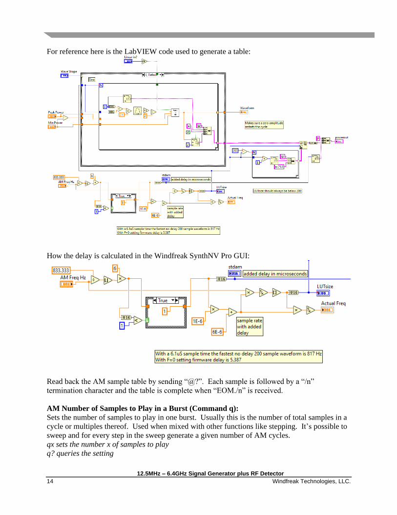
For reference here is the LabVIEW code used to generate a table:
How the delay is calculated in the Windfreak SynthNV Pro GUI:
Read back the AM sample table by sending “@?”. Each sample is followed by a “/n”
termination character and the table is complete when “EOM./n” is received.
AM Number of Samples to Play in a Burst (Command q):
Sets the number of samples to play in one burst. Usually this is the number of total samples in a
cycle or multiples thereof. Used when mixed with other functions like stepping. It’s possible to
sweep and for every step in the sweep generate a given number of AM cycles.
qx sets the number x of samples to play
q? queries the setting

12.5MHz –6.4GHz Signal Generator plus RF Detector
Windfreak Technologies, LLC. 15
AM Run Continuously (Command A):
Turns continuous AM modulation on or off.
Ax turns AM on or off with x=1=on and x=0=off
A? queries the setting
Program a Spot in the AM Lookup Table in dBm (Command @):
Programming the AM lookup table requires programming memory locations of 0-199 with an
amplitude value in dBm. The command is a series of two commands.
@xay sets value in AM LUT where x=memory value between 0 and 199, and y= value in dBm
@xa? Queries value at memory location x
Pulse Modulation Commands:
Pulse On Time (Command P):
Sets the Pulse Modulation On time in microseconds. Range is 1uS to 10,000,000 uS (10
seconds).
Px sets the on time x of the RF pulse in microseconds
P? queries the setting
Pulse Off Time (Command O):
Sets the Pulse Modulation Off time in microseconds. Range is 2uS to 10,000,000 uS (10
seconds).
Ox sets the off time x of the RF pulse in microseconds
O? queries the setting
Pulse Number of Repetitions in a Burst (Command R):
Sets the Pulse Modulation number of repetitions in a burst. Range is 1 to 65500. Burst size is
used when mixed with other functions like stepping. It’s possible to sweep and for every step in
the sweep generate the given number of Pulse On/Off cycles in the burst.
Rx sets the CW off time x of the RF pulse in microseconds
R? queries the setting
Pulse Invert Signal (Command :):
Inverts the Pulse polarity.
This feature is needed if other modulations are required inside the pulse. With a setting of 0 the
SynthNV Pro firmware will turn on the RF, delay for the on time, turn off the RF, delay for the
off time, (multiply by the burst number) and then go service other routines like USB
communication and other modulations. After setting the Invert Pulse to 1, the order is reversed
so that the RF is left on during the servicing of those routines. For example, this allows you to do
an FM chirp during the pulse on time. When Invert Pulse is ON, the On Time and Off Time get
reversed. Finally, since the PAM feature could be used on power amplifiers where the average
power is much less than the CW power, RF power is left off after the burst is finished when
Invert Pulse is set to 0. This helps protect power amplifiers. Send “h1” (RF Mute OFF) to re-
assert CW power.
:x sets the CW off time x of the RF pulse in microseconds
:? queries the setting

12.5MHz – 6.4GHz Signal Generator plus RF Detector
16 Windfreak Technologies, LLC.
Run One Pulse Burst (Command G):
Starts one cycle of a pulse burst.
G starts a burst
Run Pulse Modulation Continuously (Command j):
Starts continuous pulse amplitude modulation.
jx starts continuous pulse modulation where x=1 starts the modulation and x=0 stops the
modulation
j? queries the setting
Frequency Modulation Commands:
FM Frequency (Command <):
Sets FM modulation frequency.
<x Sets FM modulation frequency where x is frequency in Hz and the range is 1Hz – 5000Hz
<? queries the setting
FM Deviation (Command >):
Sets FM deviation frequency.
>x Sets FM modulation deviation where x is frequency in +/- Hz. The range minimum is 1 Hz
and range maximum is specified by band for the table below.
>? queries the setting
Widest FM Deviation +/-
12.5-25.0MHz = 62.5KHz
-50.0MHz = 125KHz
-100.0MHz = 250KHz
-200.0MHz = 500KHz
-400.0MHz = 1MHz
-800MHz = 2MHz
-1600MHz = 4MHz
-3200MHz = 8MHz
-6400MHz = 16MHz
(at room temperature)
FM Number of Samples in Burst (Command ,):
Sets the number of FM samples to play in one burst. Usually this is the number of total samples
in a cycle or multiples thereof. Used when mixed with other functions like stepping. It’s
possible to sweep and for every step in the sweep generate a given number of FM cycles.
,x Sets FM modulation number of samples in a burst
,? queries the setting
FM Modulation Type (Command ,):
Sets the FM modulation type to either sinusoid or chirp (ramp).
;x Sets FM modulation shape for x=0=chirp and x=1=sinusoid
;? queries the setting

12.5MHz –6.4GHz Signal Generator plus RF Detector
Windfreak Technologies, LLC. 17
Run FM Continuous Modulation (Command /):
Starts continuous frequency amplitude modulation.
/x starts continuous frequency modulation where x=1 starts the modulation and x=0 stops the
modulation
/? queries the setting
Speaker Feedback Mode (Command b):
Enables speaker feedback based on the amount of RF power detected by RFin. This feature is
experimental and should not be used with sweeps or other modulation. It may also cause large
sideband noise on the carrier of the RF signal generator. Higher amplitude RF detected result in
higher frequency audio tones from the speaker similar to a Geiger counter. Useable range is
subject to change but in the range of -40dBm to +15dBm.
bx sets speaker feedback where x=1 starts the audio and x=0 stops the audio
b? queries the setting
Query for PLL Phase Lock Status (Command p):
Checks if PLL is phase locked.
p Queries PLL to see if its locked and returns a 0=unlocked or a 1=locked
Query for Internal Temperature (Command z):
Checks the temperature of the SynthNV Pro.
z Queries temperature and returns the value in degrees C.
Show Version (Command v):
Shows the version of firmware and hardware used in the SynthNV Pro.
vx shows version where x=0 shows firmware version and x=1 shows hardware version
Show Model type (Command +):
Shows the version of firmware and hardware used in the SynthNV Pro. Example: “WFT
SynthNVP 55”
+ shows model type and serial number
Show Serial Number (Command -):
Shows the unique serial number used in the SynthNV Pro. It’s the same number as shown on the
sticker on the bottom of the device.
- shows serial number