Embed Size (px)
Citation preview

68-1552-01 Rev A 05 08Page 1
Quick ReferenceWindoWall™ Console
Menu Bar
New (Ctrl+N) – Starts a new (”Untitled”) WindoWall project by opening the WindoWall Console main window in Edit mode. Open (Ctrl+O) – Opens an existing WindoWall project file and loads its parameters into the WindoWall Console software.Open From MGP – Lets you open an existing WindoWall project that has been uploaded to a specified MGP. Save Project (Ctrl+S) – Saves the current WindoWall project file. Save Project As... – Lets you save the current WindoWall project file with a new name and/or in a new location. Most recently used – Shows a listing of the most recently opened WindoWall project files. Generate Report – Creates a multi-page report that provides information on display configuration, source settings, input/output schematics, and video wall presets for the project.Exit – Closes the current project file and the WindoWall Console application.
Contents – Displays the WindoWall Console help file. About – Displays version, part number, and copyright information about the WindoWall Console software.
New Project – Guides you through the initial setup of a WindoWall System.Auto Image – Guides you through an automatic adjustment of all of sources to produce the best possible image.Pixel Phase – Guides you through the pixel phase adjustments of each defined source device in relation to each defined display device.
Edit System (Ctrl+E) – Disconnects from the processors and the switcher, and allows you to change the system configuration.Operate System (Ctrl+R) – Connects to all processors and the switcher in your WindoWall system. Show Window Labels – Displays labels in each window on the display cube, indicating the window’s horizontal and vertical position in pixels (upper-left corner), priority level (upper-right corner), and size (lower-right corner).Show Virtual Window IDs – Displays each window‘s number, sized large and placed in the center of the window’s diagram on the canvas. Show Cube Labels – Displays labels in each display cube indicating in pixels the cube’s horizontal and vertical position (upper-left corner), and the display’s resolution (upper-right corner) and number (center).Options... – Opens the Options window from which you can set application and project options such as passwords and alerts/reminders.Test Patterns – Lets you select from 15 different test patterns that can be displayed on each display cube. Re-Build Windows – Queries all MGPs and rebuilds the canvas to match the output of the MGPs.
New
Open Save Help New (Ctrl+N) – Starts a new WindoWall project file.Open (Ctrl+O) – Opens an existing WindoWall project.Save (Ctrl+S) – Saves the current WindoWall project file.Help (F1) – Launches the WindoWall Console help file.
Menu Icons (Toolbar)

Page 5
Operate System Tabs (continued)
Canvas tab (continued)
These buttons are available when two or more windows are selected:
4. Toolbar (continued)
Align Lefts – Aligns the left edges of all selected windows with the most recently selected window.
Align Centers – Aligns the centers of the selected windows horizontally.
Align Rights – Aligns the right edges of all selected windows to the most recently selected window.
Align Tops – Aligns the top edges of all selected windows to the most recently selected window. Align Middles – Aligns the vertical centers of all selected windows with the most recently selected window.
Align Bottoms – Aligns the bottom edges of all selected windows to the most recently selected window. Make Same Width – Makes the widths of all selected windows the same as the most recently selected window.
Make Same Height – Makes the heights of all selected windows the same as the most recently selected window. Make Same Size – Makes the sizes of all selected windows the same as the most recently selected window. Make Horizontal Spacing Equal – When three or more windows are selected, creates the same amount of horizontal space between them.
Remove Horizontal Spacing – Removes any horizontal space from between selected windows. Make Vertical Spacing Equal – When three or more windows are selected, creates the same amount of vertical space between them.
Remove Vertical Spacing – Removes any vertical space from between selected windows.
Source Adjustments tabLets you fine-adjust the selected input video image.
1. Auto Image – Click this button to auto image the selected source. Auto imaging causes the source to be displayed on all display cubes, automatically setting image size, centering, and phase adjustments for the best possible video presentation.
2. Picture Controls – Provides controls for fine-adjusting the video display. Enter or select values in the following fields: Color, Tint, Contrast, Brightness, Detail (sharpness), V. Start (vertical start [location]), H. Start (horizontal start [location]), Total Pixels, Active Pixels, and Active Lines.
3. Film Mode – Select the Enable Film Mode check box to enable 3:2 (NTSC) or 2:2 (PAL) pull-down detection.
4. Window Layout Mode – Select the appropriate radio button to specify the way the input source is displayed on the display devices during adjustments:
5. Pixel Phase Wizard... – Click this button to launch the Pixel Phase Wizard, which lets you adjust the pixel phase of the input device.
6. Save – Saves the changes made to the selected source in the current project file.
Alternatively, the Auto Image Wizard lets you select multiple sources before performing the Auto Image process. Settings are automatically saved to the project file when the Auto Image process is completed.
To start this wizard, select Auto Image from the Wizards pull-down menu.
• Single source per display – Displays the entire image on each display device in the WindoWall canvas.
• Stretch source across the canvas – Displays one image stretched across all display devices in the canvas.

Page 4
Operate System Tabs
To switch to Operate mode, click Tools > Operate System. When the WindoWall Console software is in Operate mode, the following tabs are available:
Canvas tab Lets you create and position video windows on the display canvas in real time.
Transparency – Makes all the windows on the canvas translucent except those that have been selected. This does not affect the physical display.
Snap to Objects – Causes windows to snap to the edges of the displays or other windows when moved to within a few pixels of another object.
Hide/Show All Windows – Toggles all windows on the canvas on or off, on the physical display.
Show/Hide Background – Toggles the background image on or off on the physical display.
2. Canvas view – Provides a graphical representation of the physical WindoWall setup, and provides the area on which to position and size windows. In this area, you can do the following: • Create windows by dragging icons from the source view onto the canvas. • Change a source in an existing window by right-clicking on an icon in the source view and dragging it into the window. • Resize a window by dragging its handles (located at the window’s four corners and sides). • Expand a window to fill the display cube(s) in which it is located by double-clicking on the window. • Select multiple windows by holding down the Shift key while clicking on each window. • Select all windows by pressing Ctrl + A. • Delete a window by clicking on it, then pressing the Delete key. • Display a pop-up menu by right-clicking on a window in the canvas view area. This menu contains the following options for the selected window: Auto Image (if enabled), Snap to Source Native (1:1), Bring to Front, Send to Back, Lock Aspect Ratio, Lock Window, and Delete Window.
1. Source view – Shows the sources that were added to the WindoWall configuration on the Source Settings tab. Select the Thumbnails or the List radio button to display the input devices.
Bring to Front – Brings the selected window to the front of any overlapping windows.
Send to Back – Sends the selected window to the back of any overlapping windows.
Priority Up – Moves the selected window one position toward the front of all overlapping windows.
Priority Down – Moves the selected window one position toward the back of all overlapping windows.
These buttons are available when only one window is selected:
These buttons are always available, and activate or deactivate the feature:
3. Subtabs – The Canvas tab contains the following subtabs: a. Presets – Enables you to save and recall window configurations. b. Properties – Lets you change the location, size, and color of the selected window(s) and/or their text labels. c. Zoom – Lets you zoom in on the image in the selected window, drag the zoom area to a new location within the window, and change the size of the zoom area by dragging the zoom area handles. (The zooming occurs only on the physical display; it is not reflected in the canvas view.) d. Map – Lets you identify and zoom in to specific areas on the WindoWall canvas. Left-click on the canvas view or the map representation on this subtab, and drag it to pan around the display and bring a desired area into focus.
a b c d
4. Toolbar – Contains icon buttons that enable you to make adjustments to the windows on the display and/or the canvas view.

Page 3
Edit System Tabs (continued)
Source Settings tab
2. Source Configuration – Lets you add or modify a source. Name – Displays the name of the source icon that was selected in the source view field. You can also type the name of the source to be added or edited. Video Format – Select the source video type from the drop-down menu. Dynamic Input – Allows the Auto Image option to be selected on the Canvas tab. Select this check box if the source input video format is unknown or might vary. Source Icon – The icons in this field represent the types of input devices that may be part of the WindoWall system. Manage Icon... – Click to open the Icon Manager window, which lets you import (or delete) images to be used as source icons. Delete – Click this button to delete the selected source from the Source Icons field. <Add – Click to add the selected source to the icons view field. Apply Changes – Click this button to implement any changes made to the selected source.
1. Sources view – Shows sources that have been added to your WindoWall system. Thumbnails – Select this button to display large icons, arranged in horizontal rows. List – Select this button to show small icons in a column, with source names beside them.
3. Default Window Size – Lets you define the initial size of the window that will be created for the selected source. Aspect Ratio – From the drop-down menu, select the default aspect ratio of the window displaying the selected source. Width and Height – Let you select or enter the width and height of the window displaying the selected input. Lock Aspect Ratio – Select this check box to prevent changes to the window’s aspect ratio while allowing the window to be resized.
4. Window Color – In the color selector, click on the desired window color, or enter the RGB values in the fields below it.
Lets you create a connection diagram showing ties among the video input devices, the matrix switcher, and the processors (MGPs). Note: This diagram must match the physical cabling in the WindoWall system.
Provides controls for specifying source parameters and attributes. To add a source, enter a name for it, select the video format from the drop-down menu, click on an icon for the source in the Source Icon field, then click <Add.
I/O Schematics tab
2. Source icons – Represent the input sources in your WindoWall system. Drag these icons to the red Matrix Switcher graphic (#3) to create input ties.
1. Options – Contains the following buttons: Auto-Connect... – Click to create a system diagram, based on ties between sources and the switcher inputs, and between the switcher outputs and the (MGP) inputs. Clear Schematic – Click to clear all ties between system components. Switcher Properties – Click to open the Switcher Properties window, in which you can enter the matrix switcher’s communication parameters and the number of its inputs and outputs.
3. Switcher inputs – Represent the sources tied to the matrix switcher’s input connectors.
4. Switcher outputs – Represent the matrix switcher’s output connectors. To form an output tie, drag a switcher output icon to a processor input on a blue Processor graphic (#5).
5. Switcher outputs/Processor inputs – Represent the matrix switcher’s outputs tied to the MGP (processor) inputs.
Page 2
Edit System Tabs
Provides controls for setting up all video wall display parameters and processor IP address/password assignments.
To switch to Edit mode, click Tools > Edit System. When the WindoWall Console software is in Edit mode, the following tabs are available:
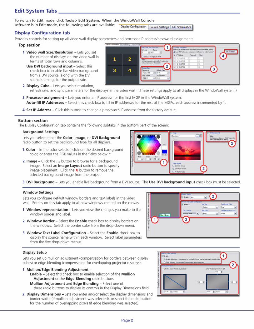
Bottom sectionThe Display Configuration tab contains the following subtabs in the bottom part of the screen:
1. Window representation – Lets you view the changes you make to the window border and label.
2. Display Dimensions – Lets you enter and/or select the display dimensions and border width (if mullion adjustment was selected), or select the radio button for the number of overlapping pixels (if edge blending was selected).
Display Configuration tab
2. Display Cube – Lets you select resolution, refresh rate, and sync parameters for the displays in the video wall. (These settings apply to all displays in the WindoWall system.)
1. Video wall Size/Resolution – Lets you set the number of displays on the video wall in terms of total rows and columns. Use DVI background input – Select this check box to enable live video background from a DVI source, along with the DVI source’s timings for the output rate.
3. Processor assignment – Lets you enter an IP address for the first MGP in the WindoWall system. Auto-fill IP Addresses – Select this check box to fill in IP addresses for the rest of the MGPs, each address incremented by 1.
4. Set IP Address – Click this button to change a processor’s IP address from the factory default.
2. Image – Click the ... button to browse for a background image. Select an Image Layout radio button to specify image placement. Click the x button to remove the selected background image from the project.
1. Color – In the color selector, click on the desired background color, or enter the RGB values in the fields below it.
3. DVI Background – Lets you enable live background from a DVI source. The Use DVI background input check box must be selected.
Background Settings
Lets you select either the Color, Image, or DVI Background radio button to set the background type for all displays.
Window Settings
Lets you configure default window borders and text labels in the video wall. Entries on this tab apply to all new windows created on the canvas.
2. Window Border – Select the Enable check box to display borders on the windows. Select the border color from the drop-down menu.
3. Window Text Label Configuration – Select the Enable check box to display the source name within each window. Select label parameters from the five drop-down menus.
Top section
Display Setup
Lets you set up mullion adjustment (compensation for borders between display cubes) or edge blending (compensation for overlapping projector displays).
1. Mullion/Edge Blending Adjustment – Enable – Select this check box to enable selection of the Mullion Adjustment or the Edge Blending radio buttons. Mullion Adjustment and Edge Blending – Select one of these radio buttons to display its controls in the Display Dimensions field.

Copyright © 2008 Extron Electronics
Create a window on the canvas? 1. Click Tools > Operate System.
2. Select the Canvas tab.
3. Click and drag a source icon from the source view area to anywhere in the canvas view area. A window is created for that input at the default size specified on the Source Settings tab.
Delete a window ? 1. Click Tools > Operate System.
2. Select the Canvas tab.
3. Click on the window in the canvas view that you want to delete.
4. Do either of the following:
• Right-click on the window and select Delete from the pop-up menu.
• Press the Delete key on your computer keyboard.
Select multiple windows to edit at the same time? 1. Click Tools > Operate System.
2. Select the Canvas tab.
3. Click on one of the windows that you want to edit.
4. Hold down the Shift key while clicking on all additional windows to be edited. Use a DVI background source?
1. Click Tools > Edit System.
2. On the Display Configuration tab, select the Use DVI background input check box.
3. Select the resolution that the DVI Background will provide. This sets the EDID information that is communicated to the DVI background source.
4. Select the Background Settings tab at the bottom of the screen.
5. Select the DVI Background radio button.
Create a new WindoWall project? 1. Click Wizards > New Project. 2. Follow the instructions on the New Project Wizard screens to set up the WindoWall system configuration.
3. Create the system diagram on the I/O Schematics screen.
4. Make the Background Setting selections (Display Configuration tab > Background Settings tab) (optional).
5. Make the Window Settings selections (Display Configuration tab > Window Settings tab) (optional).
6. If you want to make any changes to the windows, displays, and/or sources before saving the project, select the Display Configuration or Source Settings tab to make the additional edits.
7. Click File > Save Project As to save the project with a unique name.
Configure a background image? 1. Click Tools > Edit System > Display Configuration tab.
2. Select the Background Settings tab at the bottom of the screen.
3. Select the Image radio button.
4. Click the browse (...) button, and locate and open the desired image file. The image is displayed in the canvas view.
5. Select the radio button for the desired image layout: Center to Canvas, Stretch to Canvas, or Fill Display Cube.
Set the source picture controls? Using the Source Adjustments tab:
1. Click Tools > Operate System.
2. Select the Source Adjustments tab.
3. In the View section, select the icon for the input to be configured.
4. In the Picture Controls section, type or select the value(s) you want to change in the available selection boxes; or click Auto Image to automatically set all controls to provide the best possible image.
5. Click Save to implement your changes. (Skip this step if Auto Image was used in step 4).
6. Repeat steps 3 through 5 for each input to be configured.
Using the Auto Image Wizard:
1. Click Wizards > Auto Image.
2. Select the All the Sources are turned on and providing a signal check box on the first screen, then click Next. 3. Follow the instructions on the remaining wizard screens to complete Auto Image setup.
Note: Auto-Image automatically saves presets for non-dynamic sources.
How do I...?
Edit a window in Operate mode? 1. Click Tools > Operate System.
2. Select the Canvas tab.
3. Click on the window to be edited.
4. Make adjustments from either of the following areas:
Canvas:
• Change the window’s location on the canvas by dragging it to different positions within the Canvas View area.
• Change the window’s size by clicking on and dragging any of the window’s handles, located at the window’s sides and corners. The window can stretch across display cube boundaries.
• Double-click on the window to expand it to fill the display cube. If the window overlaps more than one display cube, it fills all the cubes that it touches.
• Change the window’s priority by right-clicking on it and selecting Bring to Front or Send to Back from the pop-up menu.
Properties tab:
a. Select the Properties tab in the lower-left section.
b. Click the + sign in front of the desired properties category
(Application, Window, or Text) to expand it.
c. Click on the property that you want to edit.
d. Type in a value and press the Enter key; or, if a drop-down menu appears, select an option.
e. Repeat steps b through d as desired to make additional edits.
Change a source in an existing window? 1. Click Tools > Operate System.
2. Select the Canvas tab.
3. Right-click on an icon in the source view area, and drag it onto the window in the canvas view for which you want to switch sources.
Generate a PDF report of my overall system setup? 1. Click File > Generate Report > PDF Format.
2. Enter a unique project name.
3. Enter the Dealer and the Technician names (optional).
4. Enter any pertinent Comments (optional).
5. Click Add Custom to add new types of information to the report, or Use Default to include only the default topics. The report is generated.
Page 6
Create/delete input/output ties? 1. Click Tools > Edit System.
2. Select the I/O Schematics tab.
3. To form an input tie, drag a source icon to a switcher input on the red Matrix switcher graphic.
To form an output tie, drag a switcher output icon to a processor input on a blue Processor graphic.
To delete a tie, right-click on it, then click the Delete pop-up button; or mouse over the tie and press the Delete key.