Embed Size (px)
Citation preview
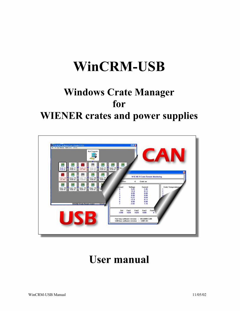
WinCRM-USB
Windows Crate Manager for
WIENER crates and power supplies
User manual
WinCRM-USB Manual 11/05/02
Table of content
1. Introduction 3
2. CAN-bus basics 4
3. Installation USB-CAN and PCAN light driver 6
4. Installation of the WIN-CRM crate manager software 9
5. WIN-CRM crate manager software 9
5.1 General Information / Program Start 10
5.2. Menu Structure 10
5.2.1 FILE Menu 11
5.2.2 CAN-BUS INTERFACE Menu 11
5.2.3 CRATE CONTROL Menu 12
5.2.4 OPTIONS Menu 15
WIENER, Plein & Baus, 11/2002 Please contact in case of questions: W-IE-NE-R, Plein & Baus GmbH Müllersbaum 20, D - 51399 Burscheid Germany PHONE.: (++ 49) 2174 678 0, FAX: (++ 49) 2174 678 555, e-mail [email protected]
WIENER, Plein & Baus, Ltd. 300 East Auburne Avenue, Springfield, OH 45505 - U.S. PHONE.: (1) 937-324-2420, FAX: (1) 937-324-2425, e-mail [email protected]
WinCRM-USB Manual 11/05/02
1. Introduction
Crate remote Control via CAN-bus WIENER powered NIM, CAMAC and VME / VXI crates as well as low voltage power supplies of the PL500 series can be equipped with a CAN-bus interface for remote monitoring and control.
Up to 126 crates can be controlled within a network. In addition to the remote on/off and SYSRES (VME) the user can control and program remotely every crate parameter via the interface such as:
• Crate Identification • All voltages and currents • Over- under voltage trip off points • Current limit adjustment to lower levels as 100% for module test procedures • Temperature measurements:
- Power supply - Fan tray air inlet - air outlet temperature: up to 8 temperature sensors (VME/VXI 6000 series, optionally)
• All status signals • Average speed of the fans and display of every single fan speed • Configuration and adjustment (for service and maintenance)
The communication between crates and host computer is based on the W-Ie-Ne-R CAN protocol characterized by functions like:
• automatic error message generation (highest priority) • minimum level of required bus activities • broadcast and group functions • task dependent priorities, equal rights for all crates
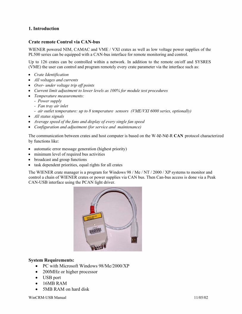
The WIENER crate manager is a program for Windows 98 / Me / NT / 2000 / XP systems to monitor and control a chain of WIENER crates or power supplies via CAN bus. Then Can-bus access is done via a Peak CAN-USB interface using the PCAN light driver.
System Requirements:
• PC with Microsoft Windows 98/Me/2000/XP • 200MHz or higher processor • USB port • 16MB RAM • 5MB RAM on hard disk
WinCRM-USB Manual 11/05/02
2. CAN-bus basics The Controller Area Network (CAN) defined by Bosch in 1985 is an advanced serial multi-master communication protocol. Due to the reliability and technical capability as well as to the available low-price system components CAN is well suited for application in field bus system. The most important features of CAN are:
• in principle unlimited number of nodes (depending on physical layer)
• serial, asynchronous, object-oriented, multi - master communication
• 2032 priorities (message IDs) in standard frame
• max. 8 data bytes per message
• CSMA-CA (collision avoidance) bus access priority controlled (ID) with non-destructive bit-wise arbitration
• wide range of transmission rates, high speed up to 1.6Mbit/s (577kbit/s information)
• real time capability, guaranteed latency time for high priority messages <134µs (1Mbit/s)
• high level of reliability and safety due to integrated error detection (HD=6), handling and confinement, less than 10-13 undetected errors per message
• twisted pair cabling, line or star topology
• variable net lengths and bit rates:
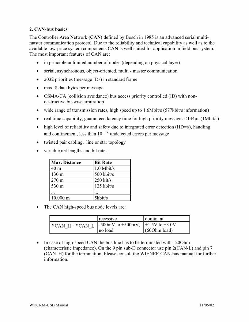
Max. Distance Bit Rate 40 m 1.0 Mbit/s 130 m 500 kbit/s 270 m 250 kit/s 530 m 125 kbit/s ... ... 10.000 m 5kbit/s
• The CAN high-speed bus node levels are:
recessive dominant VCAN_H - VCAN_L -500mV to +500mV,
no load +1.5V to +3.0V (60Ohm load)
• In case of high-speed CAN the bus line has to be terminated with 120Ohm
(characteristic impedance). On the 9 pin sub-D connector use pin 2(CAN-L) and pin 7 (CAN_H) for the termination. Please consult the WIENER CAN-bus manual for further information.
WinCRM-USB Manual 11/05/02
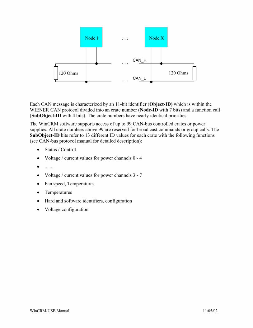
Node 1 Node X. . .
120 Ohms 120 Ohms
. . .
. . .
CAN_H
CAN_L
Each CAN message is characterized by an 11-bit identifier (Object-ID) which is within the WIENER CAN protocol divided into an crate number (Node-ID with 7 bits) and a function call (SubObject-ID with 4 bits). The crate numbers have nearly identical priorities.
The WinCRM software supports access of up to 99 CAN-bus controlled crates or power supplies. All crate numbers above 99 are reserved for broad cast commands or group calls. The SubObject-ID bits refer to 13 different ID values for each crate with the following functions (see CAN-bus protocol manual for detailed description):
• Status / Control
• Voltage / current values for power channels 0 - 4
• ........
• Voltage / current values for power channels 3 - 7
• Fan speed, Temperatures
• Temperatures
• Hard and software identifiers, configuration
• Voltage configuration
WinCRM-USB Manual 11/05/02
3. Installation USB-CAN and PCAN light driver
The PEAK-CAN-USB is a USB to CAN Converter, which allows to connect a CAN-bus network to the USB port of a personal computer.
Before plugging in the CAN-USB adapter first time please install the driver (WIN98/ME/2000/XP) provided on the CD-ROM:
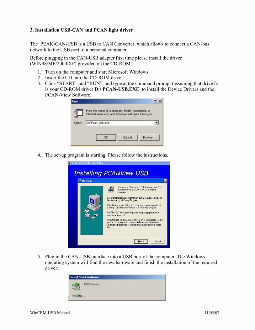
1. Turn on the computer and start Microsoft Windows 2. Insert the CD into the CD-ROM drive 3. Click “START” and “RUN”, and type at the command prompt (assuming that drive D
is your CD-ROM drive) D:\ PCAN-USB.EXE to install the Device Drivers and the PCAN-View Software.
4. The set-up program is starting. Please follow the instructions.
5. Plug in the CAN-USB interface into a USB port of the computer. The Windows
operating system will find the new hardware and finish the installation of the required driver:
WinCRM-USB Manual 11/05/02
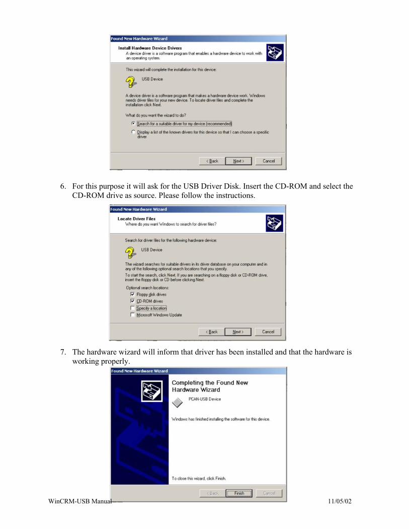
6. For this purpose it will ask for the USB Driver Disk. Insert the CD-ROM and select the CD-ROM drive as source. Please follow the instructions.
7. The hardware wizard will inform that driver has been installed and that the hardware is working properly.
WinCRM-USB Manual 11/05/02
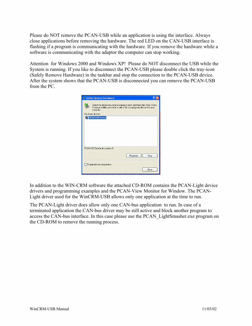
Please do NOT remove the PCAN-USB while an application is using the interface. Always close applications before removing the hardware. The red LED on the CAN-USB interface is flashing if a program is communicating with the hardware. If you remove the hardware while a software is communicating with the adaptor the computer can stop working. Attention for Windows 2000 and Windows XP! Please do NOT disconnect the USB while the System is running. If you like to disconnect the PCAN-USB please double click the tray-icon (Safely Remove Hardware) in the taskbar and stop the connection to the PCAN-USB device. After the system shows that the PCAN-USB is disconnected you can remove the PCAN-USB from the PC.
In addition to the WIN-CRM software the attached CD-ROM contains the PCAN-Light device drivers and programming examples and the PCAN-View Monitor for Window. The PCAN-Light driver used for the WinCRM-USB allows only one application at the time to run.
The PCAN-Light driver does allow only one CAN-bus application to run. In case of a terminated application the CAN-bus driver may be still active and block another program to access the CAN-bus interface. In this case please use the PCAN_LightSmasher.exe program on the CD-ROM to remove the running process.
WinCRM-USB Manual 11/05/02
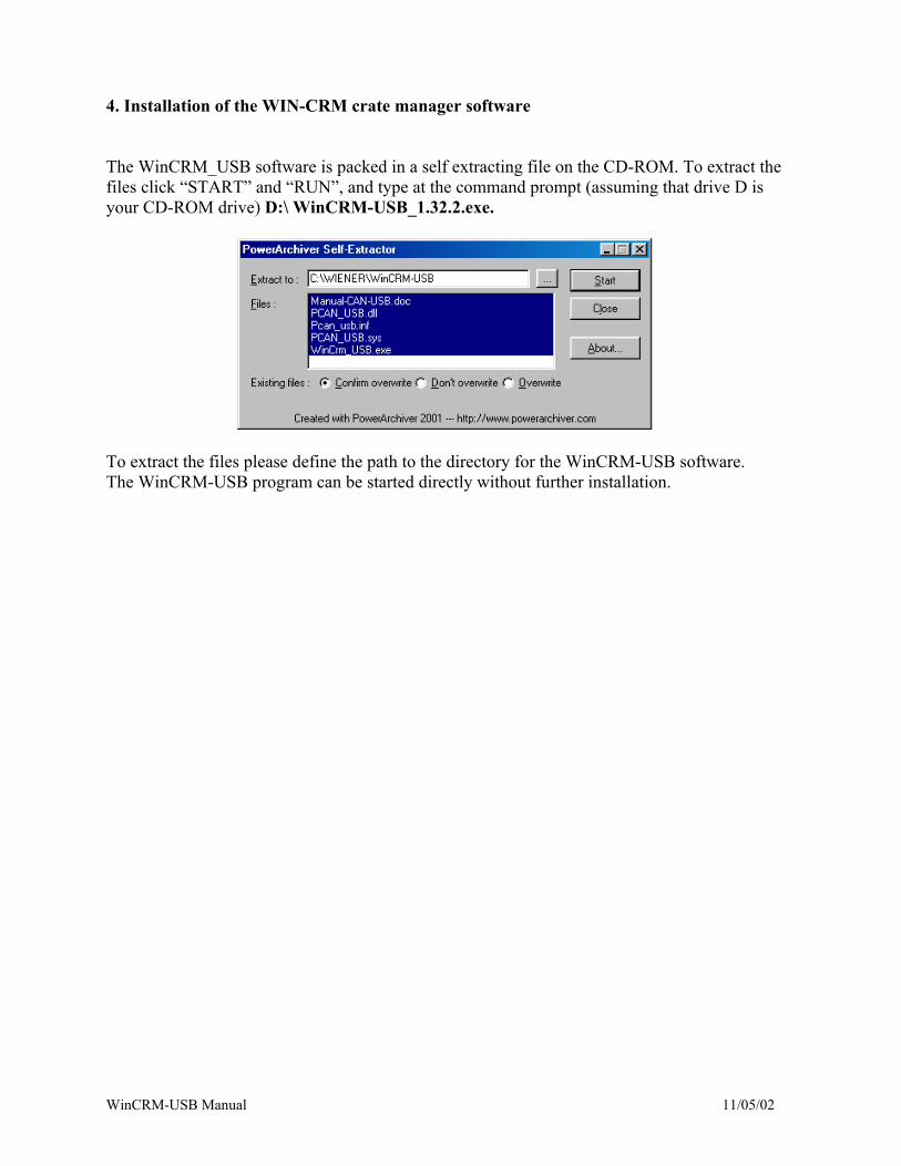
4. Installation of the WIN-CRM crate manager software The WinCRM_USB software is packed in a self extracting file on the CD-ROM. To extract the files click “START” and “RUN”, and type at the command prompt (assuming that drive D is your CD-ROM drive) D:\ WinCRM-USB_1.32.2.exe.
To extract the files please define the path to the directory for the WinCRM-USB software. The WinCRM-USB program can be started directly without further installation.
WinCRM-USB Manual 11/05/02
5. WIN-CRM crate manager software 5.1 General Information / Program Start
All WIENER NIM, CAMAC or VME / VXI crates and power supplies controlled via CAN-bus are following called “crates”.
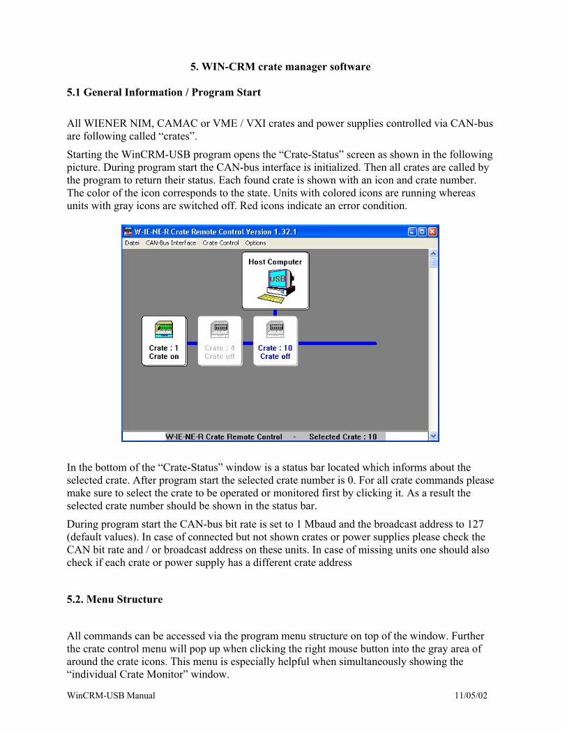
Starting the WinCRM-USB program opens the “Crate-Status” screen as shown in the following picture. During program start the CAN-bus interface is initialized. Then all crates are called by the program to return their status. Each found crate is shown with an icon and crate number. The color of the icon corresponds to the state. Units with colored icons are running whereas units with gray icons are switched off. Red icons indicate an error condition.
In the bottom of the “Crate-Status” window is a status bar located which informs about the selected crate. After program start the selected crate number is 0. For all crate commands please make sure to select the crate to be operated or monitored first by clicking it. As a result the selected crate number should be shown in the status bar.
During program start the CAN-bus bit rate is set to 1 Mbaud and the broadcast address to 127 (default values). In case of connected but not shown crates or power supplies please check the CAN bit rate and / or broadcast address on these units. In case of missing units one should also check if each crate or power supply has a different crate address
5.2. Menu Structure
All commands can be accessed via the program menu structure on top of the window. Further the crate control menu will pop up when clicking the right mouse button into the gray area of around the crate icons. This menu is especially helpful when simultaneously showing the “individual Crate Monitor” window.
WinCRM-USB Manual 11/05/02
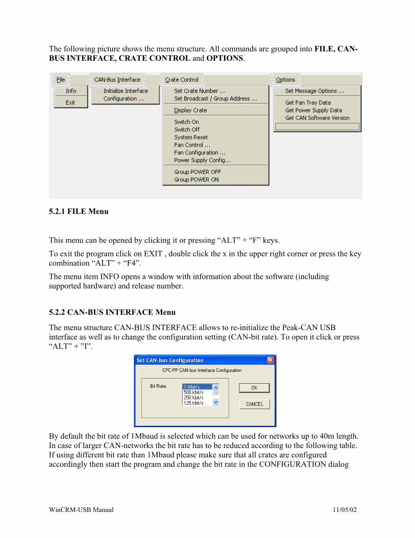
The following picture shows the menu structure. All commands are grouped into FILE, CAN-BUS INTERFACE, CRATE CONTROL and OPTIONS.
5.2.1 FILE Menu
This menu can be opened by clicking it or pressing “ALT” + “F” keys.
To exit the program click on EXIT , double click the x in the upper right corner or press the key combination “ALT” + “F4”.
The menu item INFO opens a window with information about the software (including supported hardware) and release number.
5.2.2 CAN-BUS INTERFACE Menu
The menu structure CAN-BUS INTERFACE allows to re-initialize the Peak-CAN USB interface as well as to change the configuration setting (CAN-bit rate). To open it click or press “ALT” + ”I”.
By default the bit rate of 1Mbaud is selected which can be used for networks up to 40m length. In case of larger CAN-networks the bit rate has to be reduced according to the following table. If using different bit rate than 1Mbaud please make sure that all crates are configured accordingly then start the program and change the bit rate in the CONFIGURATION dialog
WinCRM-USB Manual 11/05/02
Max. Distance Bit Rate 40 m 1.0 Mbit/s 130 m 500 kbit/s 270 m 250 kit/s 530 m 125 kbit/s ... ... 10.000 m 5kbit/s
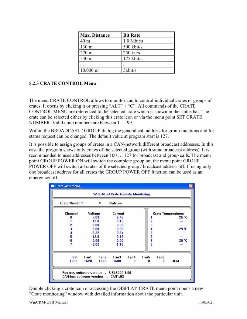
5.2.3 CRATE CONTROL Menu
The menu CRATE CONTROL allows to monitor and to control individual crates or groups of crates. It opens by clicking it or pressing “ALT” + “C”. All commands of the CRATE CONTROL MENU are referenced to the selected crate which is shown in the status bar. The crate can be selected either by clicking this crate icon or via the menu point SET CRATE NUMBER. Valid crate numbers are between 1 … 99.
Within the BROADCAST / GROUP dialog the general call address for group functions and for status request can be changed. The default value at program start is 127.
It is possible to assign groups of crates in a CAN-network different broadcast addresses. In this case the program shows only crates of the selected group (with same broadcast address). It is recommended to uses addresses between 100 … 127 for broadcast and group calls. The menu point GROUP POWER ON will switch the complete group on, the menu point GROUP POWER OFF will switch all crates of the selected group / broadcast address off. If using only one broadcast address for all crates the GROUP POWER OFF function can be used as an emergency off.
Double clicking a crate icon or accessing the DISPLAY CRATE menu point opens a new “Crate monitoring” window with detailed information about the particular unit.
WinCRM-USB Manual 11/05/02
The upper field shows the crate number and status. The status information is further presented by the color of this field, i.e. a white field indicates ON, a gray field OFF whereas a red field shows any error condition.
In the left table all voltage channels are listed with monitored voltages and currents. Please refer to the serial number sticker of the power supply, which lists all voltage channels with nominal voltages and currents. The right table informs about temperatures. Depending on the crate type this display may vary:
• NIM / CAMAC & VME/VXI 5000 series: Fan tray temperature, power supply temperature and bin temperature optional
• VME / VXI 400 / 6000 series: up to 8 bin temperature sensors (optional) • VME 100 series: no temperatures • PL6000 / PL500 series: no temperatures
All temperatures are shown in °Celsius. In case of the VME/VXI 6000 series up to 8 bin temperature sensors can be mounted above the VME/VXI modules. The CPU in the fan tray unit UEL6000 automatically detects these sensors and provides the temperature information via CAN-bus.
The bottom field of the “Crate Monitoring” windows informs about the CAN and UEL (fan tray / I/O) software release.
To close the window click the “X” in the upper right corner or the gray area of the main status window.
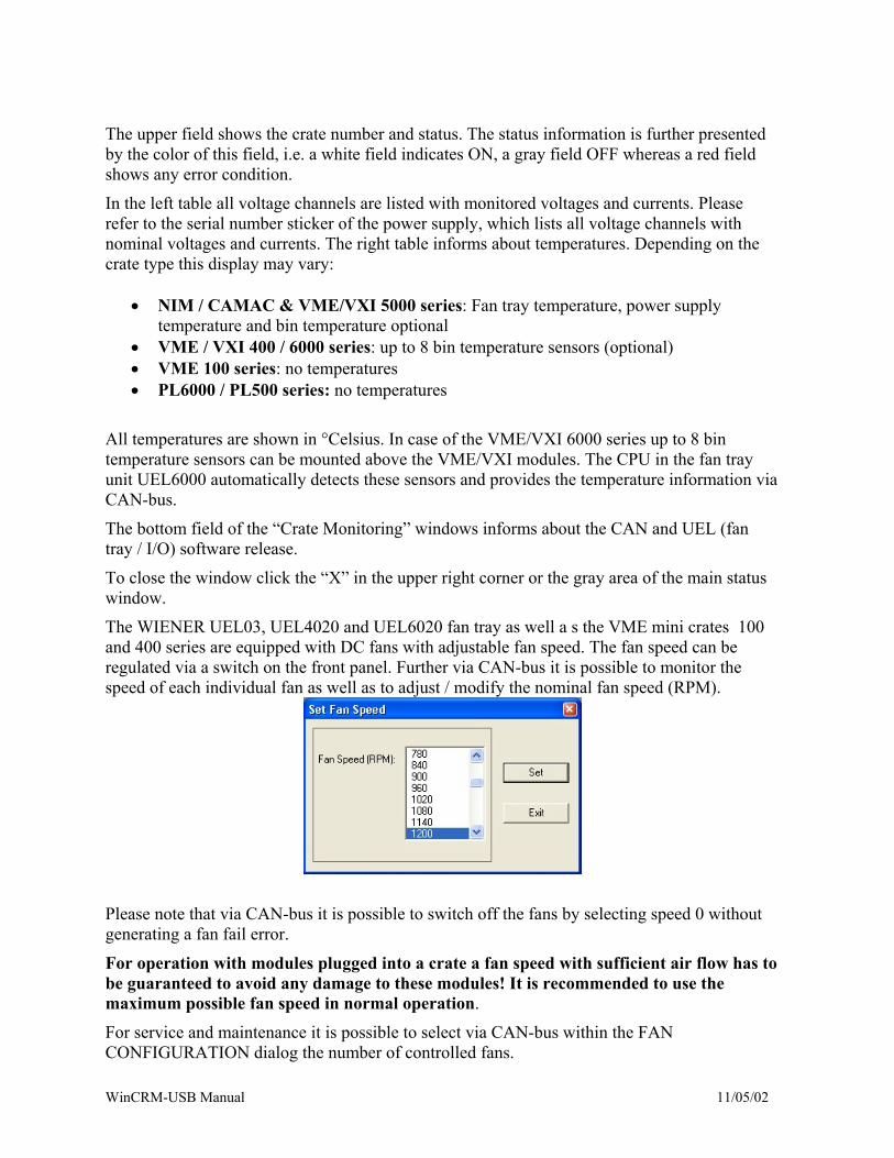
The WIENER UEL03, UEL4020 and UEL6020 fan tray as well a s the VME mini crates 100 and 400 series are equipped with DC fans with adjustable fan speed. The fan speed can be regulated via a switch on the front panel. Further via CAN-bus it is possible to monitor the speed of each individual fan as well as to adjust / modify the nominal fan speed (RPM).
Please note that via CAN-bus it is possible to switch off the fans by selecting speed 0 without generating a fan fail error.
For operation with modules plugged into a crate a fan speed with sufficient air flow has to be guaranteed to avoid any damage to these modules! It is recommended to use the maximum possible fan speed in normal operation.
For service and maintenance it is possible to select via CAN-bus within the FAN CONFIGURATION dialog the number of controlled fans.
WinCRM-USB Manual 11/05/02
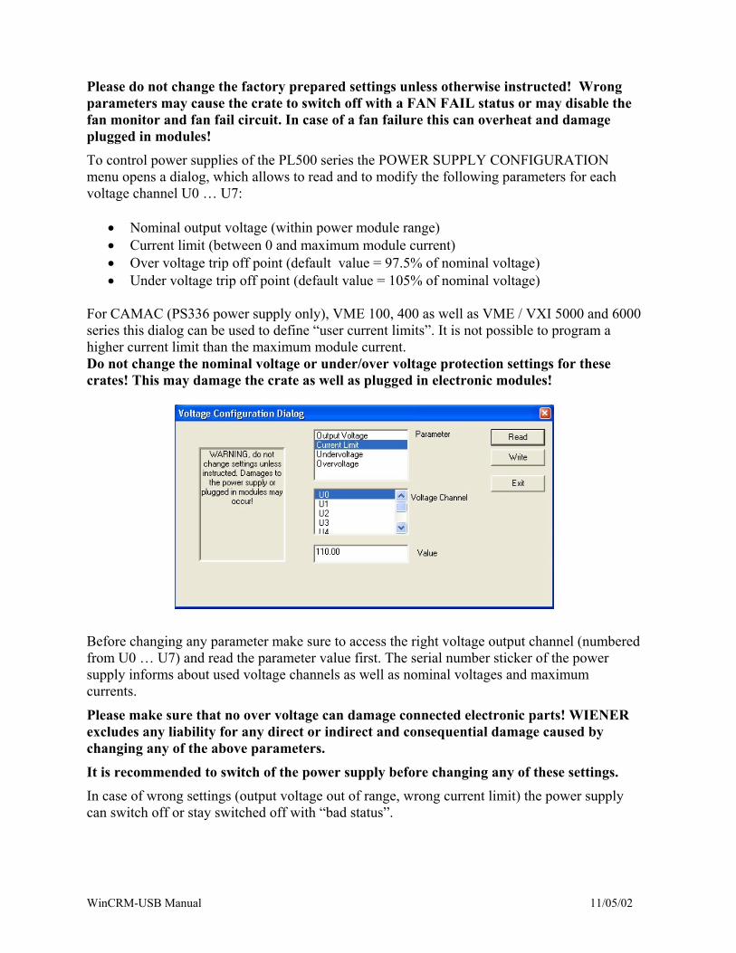
Please do not change the factory prepared settings unless otherwise instructed! Wrong parameters may cause the crate to switch off with a FAN FAIL status or may disable the fan monitor and fan fail circuit. In case of a fan failure this can overheat and damage plugged in modules! To control power supplies of the PL500 series the POWER SUPPLY CONFIGURATION menu opens a dialog, which allows to read and to modify the following parameters for each voltage channel U0 … U7:
• Nominal output voltage (within power module range) • Current limit (between 0 and maximum module current) • Over voltage trip off point (default value = 97.5% of nominal voltage) • Under voltage trip off point (default value = 105% of nominal voltage)
For CAMAC (PS336 power supply only), VME 100, 400 as well as VME / VXI 5000 and 6000 series this dialog can be used to define “user current limits”. It is not possible to program a higher current limit than the maximum module current. Do not change the nominal voltage or under/over voltage protection settings for these crates! This may damage the crate as well as plugged in electronic modules!
Before changing any parameter make sure to access the right voltage output channel (numbered from U0 … U7) and read the parameter value first. The serial number sticker of the power supply informs about used voltage channels as well as nominal voltages and maximum currents.
Please make sure that no over voltage can damage connected electronic parts! WIENER excludes any liability for any direct or indirect and consequential damage caused by changing any of the above parameters.
It is recommended to switch of the power supply before changing any of these settings. In case of wrong settings (output voltage out of range, wrong current limit) the power supply can switch off or stay switched off with “bad status”.
WinCRM-USB Manual 11/05/02
5.2.4 OPTIONS Menu
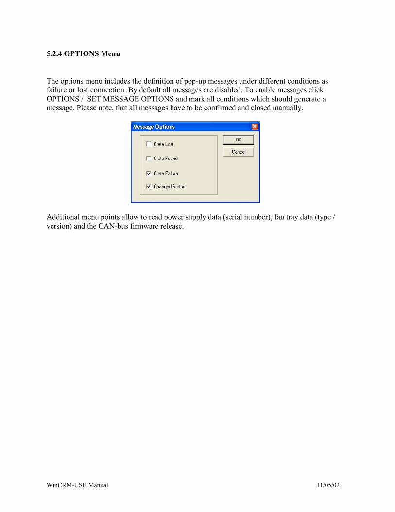
The options menu includes the definition of pop-up messages under different conditions as failure or lost connection. By default all messages are disabled. To enable messages click OPTIONS / SET MESSAGE OPTIONS and mark all conditions which should generate a message. Please note, that all messages have to be confirmed and closed manually.
Additional menu points allow to read power supply data (serial number), fan tray data (type / version) and the CAN-bus firmware release.
WinCRM-USB Manual 11/05/02