Embed Size (px)
Citation preview
www.mellanox.com Mellanox Technologies
Windows Server 2016 Hyper-Converged Cluster over Mellanox Ethernet Solution
Reference Deployment Guide
Rev 1.0
Doc #: MLNX-15-52163 Mellanox Technologies 2
Mellanox Technologies
350 Oakmead Parkway Suite 100
Sunnyvale, CA 94085
U.S.A.
www.mellanox.com
Tel: (408) 970-3400
Fax: (408) 970-3403
© Copyright 2017. Mellanox Technologies Ltd. All Rights Reserved.
Mellanox®, Mellanox logo, Accelio®, BridgeX®, CloudX logo, CompustorX®, Connect-IB®, ConnectX®,
CoolBox®, CORE-Direct®, EZchip®, EZchip logo, EZappliance®, EZdesign®, EZdriver®, EZsystem®,
GPUDirect®, InfiniHost®, InfiniBridge®, InfiniScale®, Kotura®, Kotura logo, Mellanox CloudRack®, Mellanox
CloudXMellanox®, Mellanox Federal Systems®, Mellanox HostDirect®, Mellanox Multi-Host®, Mellanox Open
Ethernet®, Mellanox OpenCloud®, Mellanox OpenCloud Logo®, Mellanox PeerDirect®, Mellanox ScalableHPC®,
Mellanox StorageX®, Mellanox TuneX®, Mellanox Connect Accelerate Outperform logo, Mellanox Virtual Modular
Switch®, MetroDX®, MetroX®, MLNX-OS®, NP-1c®, NP-2®, NP-3®, Open Ethernet logo, PhyX®, PlatformX®,
PSIPHY®, SiPhy®, StoreX®, SwitchX®, Tilera®, Tilera logo, TestX®, TuneX®, The Generation of Open Ethernet
logo, UFM®, Unbreakable Link®, Virtual Protocol Interconnect®, Voltaire® and Voltaire logo are registered
trademarks of Mellanox Technologies, Ltd.
All other trademarks are property of their respective owners.
For the most updated list of Mellanox trademarks, visit http://www.mellanox.com/page/trademarks
NOTE:
THIS HARDWARE, SOFTWARE OR TEST SUITE PRODUCT (“PRODUCT(S)”) AND ITS RELATED
DOCUMENTATION ARE PROVIDED BY MELLANOX TECHNOLOGIES “AS-IS” WITH ALL FAULTS OF ANY
KIND AND SOLELY FOR THE PURPOSE OF AIDING THE CUSTOMER IN TESTING APPLICATIONS THAT
USE THE PRODUCTS IN DESIGNATED SOLUTIONS. THE CUSTOMER'S MANUFACTURING TEST
ENVIRONMENT HAS NOT MET THE STANDARDS SET BY MELLANOX TECHNOLOGIES TO FULLY
QUALIFY THE PRODUCT(S) AND/OR THE SYSTEM USING IT. THEREFORE, MELLANOX TECHNOLOGIES
CANNOT AND DOES NOT GUARANTEE OR WARRANT THAT THE PRODUCTS WILL OPERATE WITH THE
HIGHEST QUALITY. ANY EXPRESS OR IMPLIED WARRANTIES, INCLUDING, BUT NOT LIMITED TO, THE
IMPLIED WARRANTIES OF MERCHANTABILITY, FITNESS FOR A PARTICULAR PURPOSE AND
NONINFRINGEMENT ARE DISCLAIMED. IN NO EVENT SHALL MELLANOX BE LIABLE TO CUSTOMER OR
ANY THIRD PARTIES FOR ANY DIRECT, INDIRECT, SPECIAL, EXEMPLARY, OR CONSEQUENTIAL
DAMAGES OF ANY KIND (INCLUDING, BUT NOT LIMITED TO, PAYMENT FOR PROCUREMENT OF
SUBSTITUTE GOODS OR SERVICES; LOSS OF USE, DATA, OR PROFITS; OR BUSINESS INTERRUPTION)
HOWEVER CAUSED AND ON ANY THEORY OF LIABILITY, WHETHER IN CONTRACT, STRICT LIABILITY,
OR TORT (INCLUDING NEGLIGENCE OR OTHERWISE) ARISING IN ANY WAY FROM THE USE OF THE
PRODUCT(S) AND RELATED DOCUMENTATION EVEN IF ADVISED OF THE POSSIBILITY OF SUCH
DAMAGE.
3 Mellanox Technologies Rev 1.0
Table of Contents
Revision ...................................................................................................................................... 6
Purpose ....................................................................................................................................... 7
1 Introduction........................................................................................................................... 8
2 Overview ............................................................................................................................... 9
3 System Configuration ..........................................................................................................10
3.1 Network Components....................................................................................................10
3.1.1 Network Design ...............................................................................................10
3.1.2 Logical Networks Configuration.........................................................................11
3.1.3 Servers Network Configuration .........................................................................11
3.1.4 DHCP Service Configuration.............................................................................11
3.2 Rack Design and Hardware components ........................................................................12
4 System Deployment .............................................................................................................13
4.1 Configuring Domain Firewall Policy ................................................................................13
4.2 Deploying Windows Server on the Compute Nodes ........................................................13
4.3 Configuring the Network with SCVMM 2016 ...................................................................14
4.3.1 Setting up Network Settings in SCVMM .............................................................14
4.3.2 Setting up the Host Group ................................................................................14
4.3.3 Adding Compute Hosts to SCVMM....................................................................15
4.3.4 Creating Logical Networks (MGMT, Cluster, LiveMigration and Storage) .............17
4.3.5 Creating a Logical Switch .................................................................................18
4.3.6 Deploying a Logical Switch on Compute Hosts ..................................................20
4.4 Disabling Regular Flow Control and Creating an Affinity between a Virtual NIC (vNIC) and a
Physical NIC (pNIC) ...............................................................................................................20
4.5 Create and Configure Storage Spaces Direct Cluster ......................................................21
Appendix A: Switch Configuration Examples .....................................................................24
A.1 TOR-1 Configuration Example .......................................................................................24
A.2 TOR-2 Configuration Example .......................................................................................28
Appendix B: PowerShell Script to Create Logical Networks in SCVMM .............................32
Appendix C: VM Fleet Cluster Performance Test................................................................36
Rev 1.0 Mellanox Technologies 4
List of Figures
Figure 1: Hyper-Converged Cluster Configured for Storage Spaces Direct and Virtual Machines Hosting............... 9
Figure 2: Solution High-Level Design....................................................................................................................................10
Figure 3: Solution Rack Configuration using Mellanox SN2700 Switch Systems .........................................................12
5 Mellanox Technologies Rev 1.0
List of Tables
Table 1: Revision ........................................................................................................................................................................ 6
Table 2: Abbreviation................................................................................................................................................................ 7
Table 3: Related Documentation ............................................................................................................................................ 7
Table 4: Cluster Networks ......................................................................................................................................................11
Table 5: Server Names and Network Configuration..........................................................................................................11
Rev 1.0 Mellanox Technologies 6
Revision
Table 1: Revision
Revision Date Description
1.0 February 26, 2017 Initial release of this version.
7 Mellanox Technologies Rev 1.0
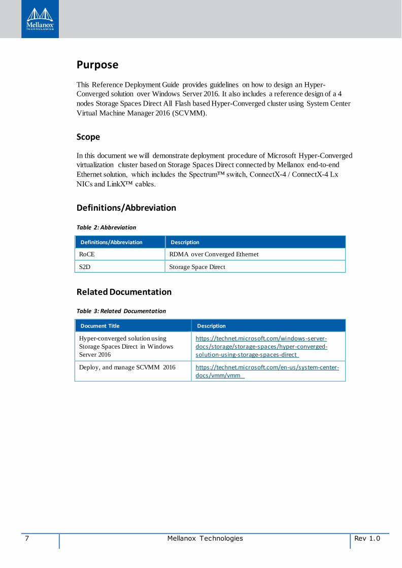
Purpose
This Reference Deployment Guide provides guidelines on how to design an Hyper-
Converged solution over Windows Server 2016. It also includes a reference design of a 4
nodes Storage Spaces Direct All Flash based Hyper-Converged cluster using System Center
Virtual Machine Manager 2016 (SCVMM).
Scope
In this document we will demonstrate deployment procedure of Microsoft Hyper-Converged
virtualization cluster based on Storage Spaces Direct connected by Mellanox end-to-end
Ethernet solution, which includes the Spectrum™ switch, ConnectX-4 / ConnectX-4 Lx
NICs and LinkX™ cables.
Definitions/Abbreviation
Table 2: Abbreviation
Definitions/Abbreviation Description
RoCE RDMA over Converged Ethernet
S2D Storage Space Direct
Related Documentation
Table 3: Related Documentation
Document Title Description
Hyper-converged solution using
Storage Spaces Direct in Windows
Server 2016
https://technet.microsoft.com/windows-server-docs/storage/storage-spaces/hyper-converged-solution-using-storage-spaces-direct
Deploy, and manage SCVMM 2016 https://technet.microsoft.com/en-us/system-center-docs/vmm/vmm
Rev 1.0 Mellanox Technologies 8
1 Introduction
This Reference Deployment Guide provides guidelines on how to design the Hyper-
Converged solution over Windows Server 2016. It includes a reference design of a 4 nodes
Spaces Direct All Flash Storage based Hyper-Converged cluster using System Center Virtual
Machine Manager (SCVMM). This guide also includes detailed instructions on how to
install and configure the components of a Hyper-Converged system using SCVMM 2016.
The act of deploying a Hyper-Converged system can be divided into three high level phases:
Deploy Windows Server 2016
Configure the network with SCVMM 2016
Configure Storage Spaces Direct Cluster
For further information on what Hyper-converged cluster with Storage Space Direct is, and
how to plan your infrastructure and deployment, please refer to the following link:
Hyper-converged solution using Storage Spaces Direct in Windows Server 2016
Deployment of SCVMM 2016 is not described in this guide. For information of how to
deploy, and manage SCVMM 2016, please refer to the following link:
https://technet.microsoft.com/en-us/system-center-docs/vmm/vmm.
9 Mellanox Technologies Rev 1.0
2 Overview
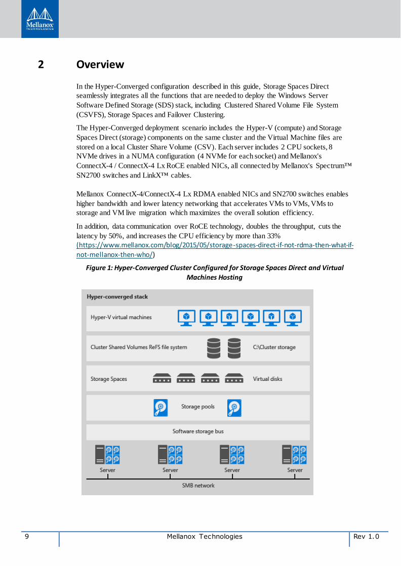
In the Hyper-Converged configuration described in this guide, Storage Spaces Direct
seamlessly integrates all the functions that are needed to deploy the Windows Server
Software Defined Storage (SDS) stack, including Clustered Shared Volume File System
(CSVFS), Storage Spaces and Failover Clustering.
The Hyper-Converged deployment scenario includes the Hyper-V (compute) and Storage
Spaces Direct (storage) components on the same cluster and the Virtual Machine files are
stored on a local Cluster Share Volume (CSV). Each server includes 2 CPU sockets, 8
NVMe drives in a NUMA configuration (4 NVMe for each socket) and Mellanox's
ConnectX-4 / ConnectX-4 Lx RoCE enabled NICs, all connected by Mellanox's Spectrum™
SN2700 switches and LinkX™ cables.
Mellanox ConnectX-4/ConnectX-4 Lx RDMA enabled NICs and SN2700 switches enables
higher bandwidth and lower latency networking that accelerates VMs to VMs, VMs to
storage and VM live migration which maximizes the overall solution efficiency.
In addition, data communication over RoCE technology, doubles the throughput, cuts the
latency by 50%, and increases the CPU efficiency by more than 33%
(https://www.mellanox.com/blog/2015/05/storage-spaces-direct-if-not-rdma-then-what-if-
not-mellanox-then-who/)
Figure 1: Hyper-Converged Cluster Configured for Storage Spaces Direct and Virtual
Machines Hosting
Rev 1.0 Mellanox Technologies 10
3 System Configuration
3.1 Network Components
3.1.1 Network Design
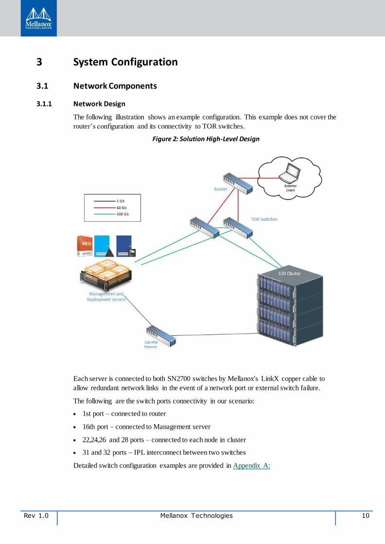
The following illustration shows an example configuration. This example does not cover the
router’s configuration and its connectivity to TOR switches.
Figure 2: Solution High-Level Design
Each server is connected to both SN2700 switches by Mellanox's LinkX copper cable to
allow redundant network links in the event of a network port or external switch failure.
The following are the switch ports connectivity in our scenario:
1st port – connected to router
16th port – connected to Management server
22,24,26 and 28 ports – connected to each node in cluster
31 and 32 ports – IPL interconnect between two switches
Detailed switch configuration examples are provided in Appendix A:
11 Mellanox Technologies Rev 1.0
3.1.2 Logical Networks Configuration
The table below shows the configuration of networks with VLAN ID for SN2700 switches.
Table 4: Cluster Networks
Network
Name
Subnet Mask VLAN ID Gateway DNS server
Deploy 172.21.0.0 16 Native(621) 172.21.1.254 172.16.1.251
MGMT 172.16.0.0 16 616 172.16.254.253 172.16.1.251
Cluster 172.17.0.0 16 617 172.17.1.253 No
LiveMigration 172.18.0.0 16 618 172.18.1.253 No
Storage 172.19.0.0 16 619 172.19.1.253 No
3.1.3 Servers Network Configuration
The table below shows the server names and their network configuration.
Table 5: Server Names and Network Configuration
Server type Server name IP and NICS
Deploy network MGMT network
DC (AD DS, DNS,
DHCP) clx-wrd-dc Not part of this network
IP:1 72.16.1.251/16
GW: 172.16.254.253
DNS: 172.16.1.251
SCVMM clx-wrd-vmm Not part of this network
IP:172.16.1.250/16
GW:172.16.254.253
DNS: 172.16.1.251
Compute, Storage clx-wrd-s1 By DHCP from DC From Pool via SCVMM
Compute, Storage clx-wrd-s2 By DHCP from DC From Pool via SCVMM
Compute, Storage clx-wrd-s3 By DHCP from DC From Pool via SCVMM
Compute, Storage clx-wrd-s4 By DHCP from DC From Pool via SCVMM
3.1.4 DHCP Service Configuration
Domain Controller (DC) will provide the DHCP service for the Deploy network. The DHCP
Deploy scope should be configured according to the information below:
IP: 172.21.1.1-100/16
GW: 172.21.1.254
DNS: 172.16.1.251
Rev 1.0 Mellanox Technologies 12
3.2 Rack Design and Hardware components
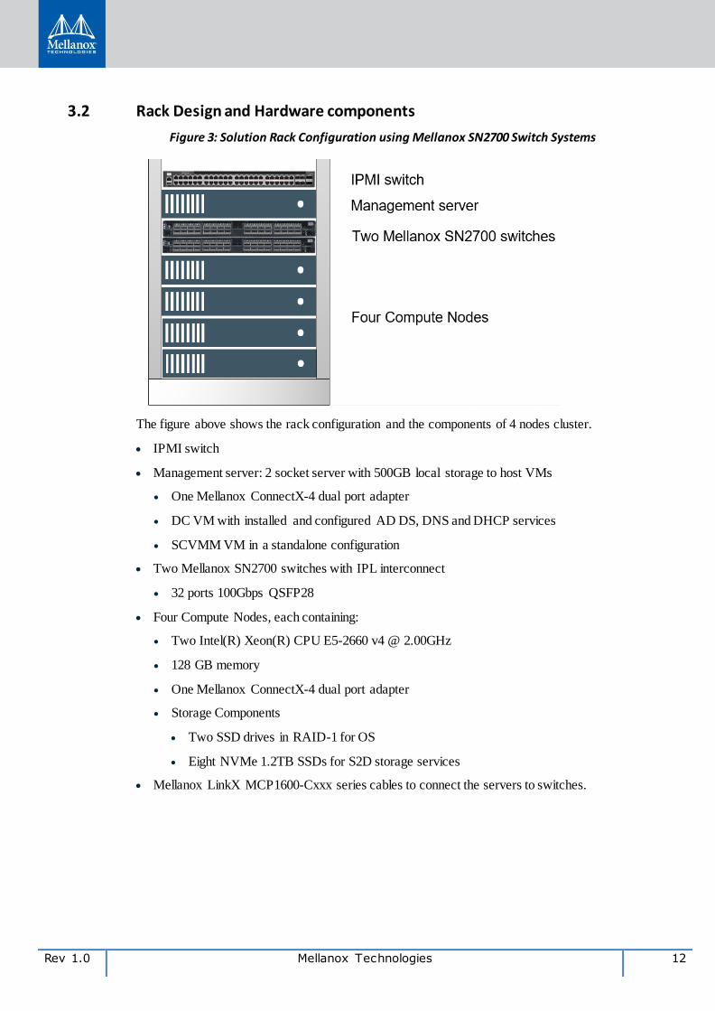
Figure 3: Solution Rack Configuration using Mellanox SN2700 Switch Systems
The figure above shows the rack configuration and the components of 4 nodes cluster.
IPMI switch
Management server: 2 socket server with 500GB local storage to host VMs
One Mellanox ConnectX-4 dual port adapter
DC VM with installed and configured AD DS, DNS and DHCP services
SCVMM VM in a standalone configuration
Two Mellanox SN2700 switches with IPL interconnect
32 ports 100Gbps QSFP28
Four Compute Nodes, each containing:
Two Intel(R) Xeon(R) CPU E5-2660 v4 @ 2.00GHz
128 GB memory
One Mellanox ConnectX-4 dual port adapter
Storage Components
Two SSD drives in RAID-1 for OS
Eight NVMe 1.2TB SSDs for S2D storage services
Mellanox LinkX MCP1600-Cxxx series cables to connect the servers to switches.
13 Mellanox Technologies Rev 1.0
4 System Deployment
4.1 Configuring Domain Firewall Policy
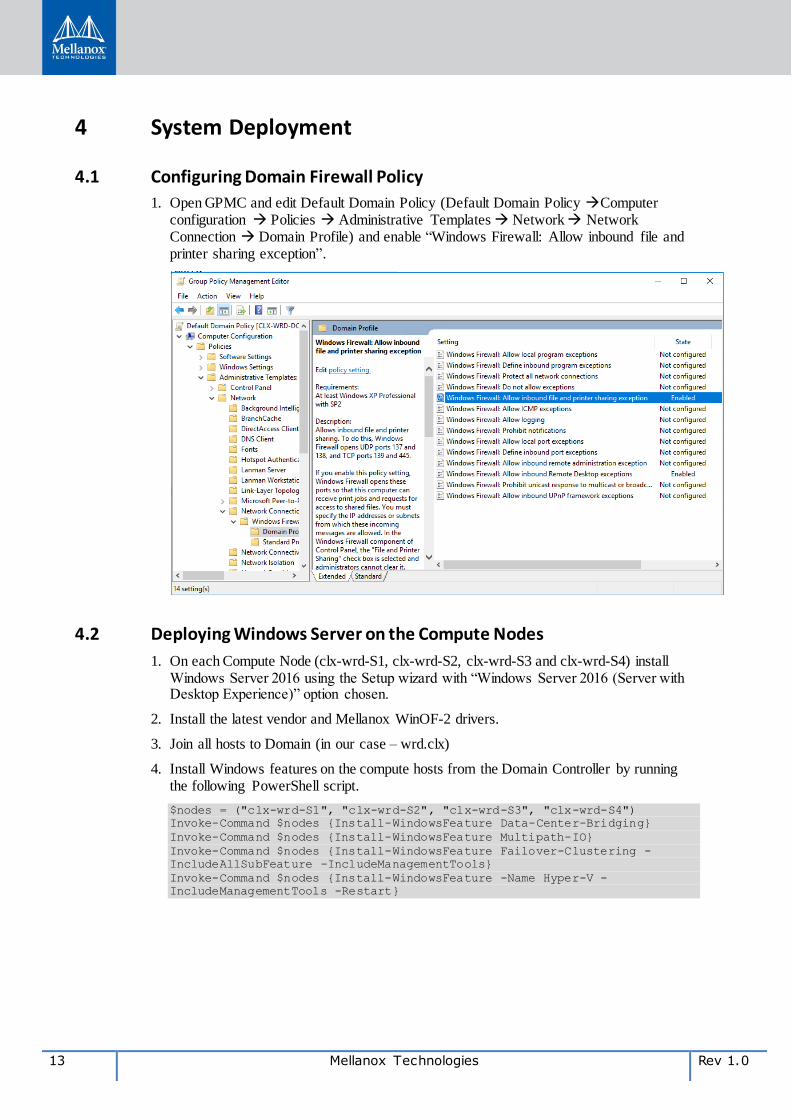
1. Open GPMC and edit Default Domain Policy (Default Domain Policy Computer configuration Policies Administrative Templates Network Network Connection Domain Profile) and enable “Windows Firewall: Allow inbound file and printer sharing exception”.
4.2 Deploying Windows Server on the Compute Nodes
1. On each Compute Node (clx-wrd-S1, clx-wrd-S2, clx-wrd-S3 and clx-wrd-S4) install Windows Server 2016 using the Setup wizard with “Windows Server 2016 (Server with Desktop Experience)” option chosen.
2. Install the latest vendor and Mellanox WinOF-2 drivers.
3. Join all hosts to Domain (in our case – wrd.clx)
4. Install Windows features on the compute hosts from the Domain Controller by running the following PowerShell script.
$nodes = ("clx-wrd-S1", "clx-wrd-S2", "clx-wrd-S3", "clx-wrd-S4")
Invoke-Command $nodes {Install-WindowsFeature Data-Center-Bridging}
Invoke-Command $nodes {Install-WindowsFeature Multipath-IO}
Invoke-Command $nodes {Install-WindowsFeature Failover-Clustering -
IncludeAllSubFeature -IncludeManagementTools}
Invoke-Command $nodes {Install-WindowsFeature -Name Hyper-V -
IncludeManagementTools -Restart}
Rev 1.0 Mellanox Technologies 14
5. Enable Network Quality of Service (QoS) in the Domain Controller by running the following PowerShell script.
$nodes = ("clx-wrd-S1", "clx-wrd-S2", "clx-wrd-S3", "clx-wrd-S4")
Invoke-Command $nodes {Get-NetAdapter | ? InterfaceDescription -Match
"Mellanox*" | Sort-Object number |% {$_ | Set-NetAdapterAdvancedProperty
-RegistryKeyword "*JumboPacket" -RegistryValue 9000}}
Invoke-Command $nodes {New-NetQosPolicy “SMB” –
NetDirectPortMatchCondition 445 –PriorityValue8021Action 3}
Invoke-Command $nodes {Enable-NetQosFlowControl –Priority 3}
Invoke-Command $nodes {Disable-NetQosFlowControl –Priority 0,1,2,4,5,6,7}
Invoke-Command $nodes {Get-NetAdapter | ? InterfaceDescription -Match
"Mellanox" | Enable-NetAdapterQos}
Invoke-Command $nodes {New-NetQosTrafficClass "SMB" -Priority 3 -
BandwidthPercentage 50 -Algorithm ETS}
4.3 Configuring the Network with SCVMM 2016
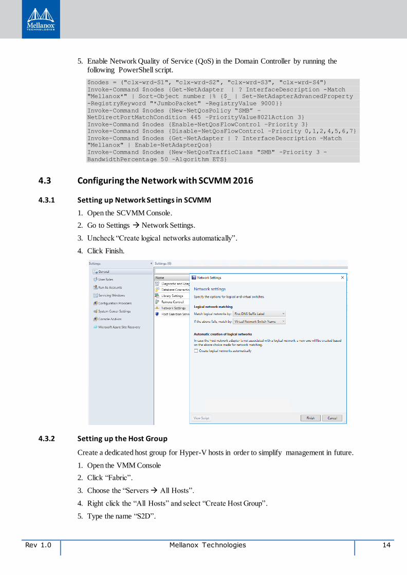
4.3.1 Setting up Network Settings in SCVMM
1. Open the SCVMM Console.
2. Go to Settings Network Settings.
3. Uncheck “Create logical networks automatically”.
4. Click Finish.
4.3.2 Setting up the Host Group
Create a dedicated host group for Hyper-V hosts in order to simplify management in future.
1. Open the VMM Console
2. Click “Fabric”.
3. Choose the “Servers All Hosts”.
4. Right click the “All Hosts” and select “Create Host Group”.
5. Type the name “S2D”.
15 Mellanox Technologies Rev 1.0
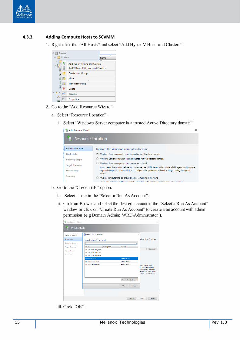
4.3.3 Adding Compute Hosts to SCVMM
1. Right click the “All Hosts” and select “Add Hyper-V Hosts and Clusters”.
2. Go to the “Add Resource Wizard”.
a. Select “Resource Location”.
i. Select “Windows Server computer in a trusted Active Directory domain”.
b. Go to the “Credentials” option.
i. Select a user in the “Select a Run As Account”.
ii. Click on Browse and select the desired account in the “Select a Run As Account”
window or click on “Create Run As Account” to create a an account with admin
permission (e.g Domain Admin: WRD\Administrator ).
iii. Click “OK”.
Rev 1.0 Mellanox Technologies 16
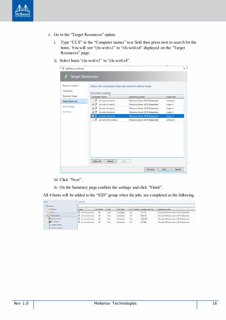
c. Go to the “Target Resources” option.
i. Type “CLX” in the “Computer names” text field then press next to search for the
hosts. You will see “clx-wrd-s1” to “clx-wrd-s4” displayed on the “Target
Resources” page.
ii. Select hosts “clx-wrd-s1” to “clx-wrd-s4”.
iii. Click “Next”.
iv. On the Summary page confirm the settings and click “Finish”.
All 4 hosts will be added to the “S2D” group when the jobs are completed as the following.
17 Mellanox Technologies Rev 1.0
4.3.4 Creating Logical Networks (MGMT, Cluster, LiveMigration and Storage)
Below we explain two ways how-to create logical networks with SCVMM server.
4.3.4.1 Automated Logical Networks Creation by PowerShell Script
Use the PowerShell script provided in Appendix B: Change the script’s parameters according
to your infrastructure and run it in PowerShell session from the SCVMM server.
4.3.4.2 Manual Logical Networks Creation with SCVMM GUI
Repeat the logical network and IP Address Pool creation for All Logical Networks according
to the below example:
Create the Logical Network
1. Click “Fabric” “Networking”.
2. Right-click “Logical Networks” “Create Logical Network”.
3. Specify “MGMT” as a “Name” and optional “Description”.
4. In “Settings” select “One Connected Network”. All management networks need to have routing and connectivity between all hosts in that network.
5. Select “Create a VM network” with the same name to allow Virtual Machines to access this logical network directly to automatically create a VM network for your management network.
6. Click “Network Site” Add.
7. Select the host group for the hosts that will be managed by the network controller.
8. Insert your management network IP subnet details. This network should already exist and be configured in your physical switch.
9. Review the Summary information and click “Finish”.
Create an IP Address Pool for Management Logical Network
In order to allocate static IP addresses to compute hosts, create an IP address pool in the
management logical network. If you are using DHCP, you can skip the steps below.
1. In the VMM console, right-click the Management Logical Network in “Create IP Pool”.
2. Provide “MGMT_Pool” as a “Name” and optional “Description” for the pool and ensure that the Management Network is selected for the logical network.
3. In “Network Site” panel, select the subnet that this IP address pool will service.
4. In “IP Address Range” panel, type the starting and ending IP addresses.
5. To use an IP as Cluster IP, type one of the IP addresses from the specified range in IP addresses to be reserved for other uses box. Note: Do not use the first three IP addresses of your available subnet. For example, if your available subnet is from .1 to .254, start your range at .4 or greater.
6. Specify the default gateway address, DNS address and optionally configure the WINS settings.
Rev 1.0 Mellanox Technologies 18
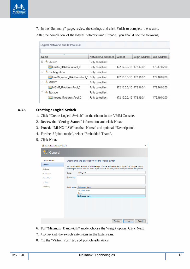
7. In the “Summary” page, review the settings and click Finish to complete the wizard.
After the completion of the logical networks and IP pools, you should see the following.
4.3.5 Creating a Logical Switch
1. Click “Create Logical Switch” on the ribbon in the VMM Console.
2. Review the “Getting Started” information and click Next.
3. Provide “MLNX-LSW” as the “Name” and optional “Description”.
4. For the “Uplink mode”, select “Embedded Team”.
5. Click Next.
6. For “Minimum Bandwidth” mode, choose the Weight option. Click Next.
7. Uncheck all the switch extensions in the Extensions.
8. On the “Virtual Port” tab add port classifications.
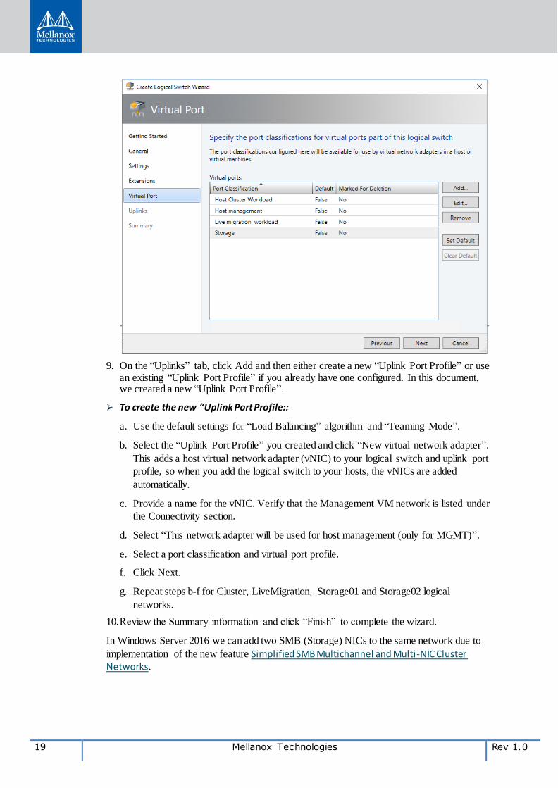
19 Mellanox Technologies Rev 1.0
9. On the “Uplinks” tab, click Add and then either create a new “Uplink Port Profile” or use an existing “Uplink Port Profile” if you already have one configured. In this document, we created a new “Uplink Port Profile”.
To create the new “Uplink Port Profile::
a. Use the default settings for “Load Balancing” algorithm and “Teaming Mode”.
b. Select the “Uplink Port Profile” you created and click “New virtual network adapter”.
This adds a host virtual network adapter (vNIC) to your logical switch and uplink port
profile, so when you add the logical switch to your hosts, the vNICs are added
automatically.
c. Provide a name for the vNIC. Verify that the Management VM network is listed under
the Connectivity section.
d. Select “This network adapter will be used for host management (only for MGMT)”.
e. Select a port classification and virtual port profile.
f. Click Next.
g. Repeat steps b-f for Cluster, LiveMigration, Storage01 and Storage02 logical
networks.
10. Review the Summary information and click “Finish” to complete the wizard.
In Windows Server 2016 we can add two SMB (Storage) NICs to the same network due to
implementation of the new feature Simplified SMB Multichannel and Multi-NIC Cluster Networks.
Rev 1.0 Mellanox Technologies 20
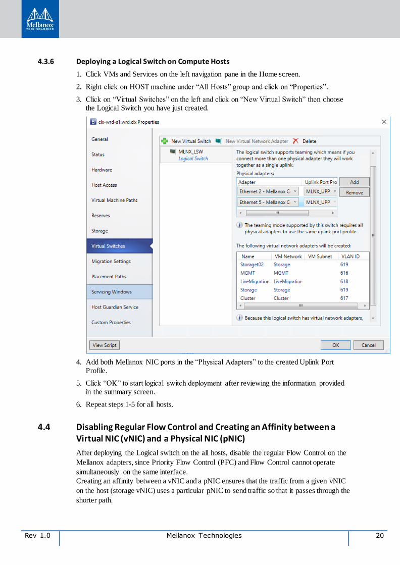
4.3.6 Deploying a Logical Switch on Compute Hosts
1. Click VMs and Services on the left navigation pane in the Home screen.
2. Right click on HOST machine under “All Hosts” group and click on “Properties” .
3. Click on “Virtual Switches” on the left and click on “New Virtual Switch” then choose the Logical Switch you have just created.
4. Add both Mellanox NIC ports in the “Physical Adapters” to the created Uplink Port Profile.
5. Click “OK” to start logical switch deployment after reviewing the information provided in the summary screen.
6. Repeat steps 1-5 for all hosts.
4.4 Disabling Regular Flow Control and Creating an Affinity between a Virtual NIC (vNIC) and a Physical NIC (pNIC)
After deploying the Logical switch on the all hosts, disable the regular Flow Control on the
Mellanox adapters, since Priority Flow Control (PFC) and Flow Control cannot operate
simultaneously on the same interface.
Creating an affinity between a vNIC and a pNIC ensures that the traffic from a given vNIC
on the host (storage vNIC) uses a particular pNIC to send traffic so that it passes through the
shorter path.
21 Mellanox Technologies Rev 1.0
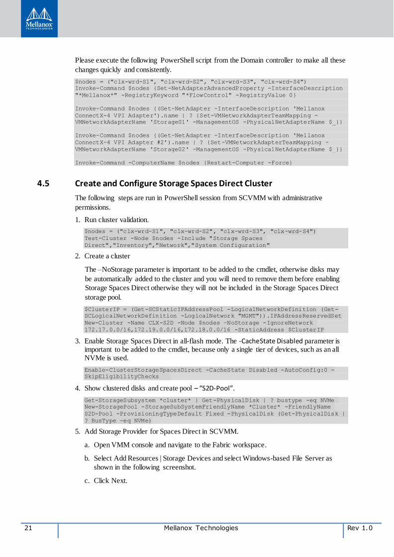
Please execute the following PowerShell script from the Domain controller to make all these
changes quickly and consistently.
$nodes = ("clx-wrd-S1", "clx-wrd-S2", "clx-wrd-S3", "clx-wrd-S4")
Invoke-Command $nodes {Set-NetAdapterAdvancedProperty -InterfaceDescription
"*Mellanox*" -RegistryKeyword "*FlowControl" -RegistryValue 0}
Invoke-Command $nodes {(Get-NetAdapter -InterfaceDescription 'Mellanox
ConnectX-4 VPI Adapter').name | ? {Set-VMNetworkAdapterTeamMapping -
VMNetworkAdapterName 'Storage01' -ManagementOS -PhysicalNetAdapterName $_}}
Invoke-Command $nodes {(Get-NetAdapter -InterfaceDescription 'Mellanox
ConnectX-4 VPI Adapter #2').name | ? {Set-VMNetworkAdapterTeamMapping -
VMNetworkAdapterName 'Storage02' -ManagementOS -PhysicalNetAdapterName $_}}
Invoke-Command -ComputerName $nodes {Restart-Computer -Force}
4.5 Create and Configure Storage Spaces Direct Cluster
The following steps are run in PowerShell session from SCVMM with administrative
permissions.
1. Run cluster validation.
$nodes = ("clx-wrd-S1", "clx-wrd-S2", "clx-wrd-S3", "clx-wrd-S4")
Test-Cluster -Node $nodes -Include "Storage Spaces
Direct","Inventory","Network","System Configuration"
2. Create a cluster
The –NoStorage parameter is important to be added to the cmdlet, otherwise disks may
be automatically added to the cluster and you will need to remove them before enabling
Storage Spaces Direct otherwise they will not be included in the Storage Spaces Direct
storage pool.
$ClusterIP = (Get-SCStaticIPAddressPool -LogicalNetworkDefinition (Get-
SCLogicalNetworkDefinition -LogicalNetwork "MGMT")).IPAddressReservedSet
New-Cluster -Name CLX-S2D -Node $nodes –NoStorage -IgnoreNetwork
172.17.0.0/16,172.19.0.0/16,172.18.0.0/16 -StaticAddress $ClusterIP
3. Enable Storage Spaces Direct in all-flash mode. The -CacheState Disabled parameter is important to be added to the cmdlet, because only a single tier of devices, such as an all NVMe is used.
Enable-ClusterStorageSpacesDirect -CacheState Disabled -AutoConfig:0 -
SkipEligibilityChecks
4. Show clustered disks and create pool – “S2D-Pool”.
Get-StorageSubsystem *cluster* | Get-PhysicalDisk | ? bustype -eq NVMe
New-StoragePool -StorageSubSystemFriendlyName *Cluster* -FriendlyName
S2D-Pool -ProvisioningTypeDefault Fixed -PhysicalDisk (Get-PhysicalDisk |
? BusType -eq NVMe)
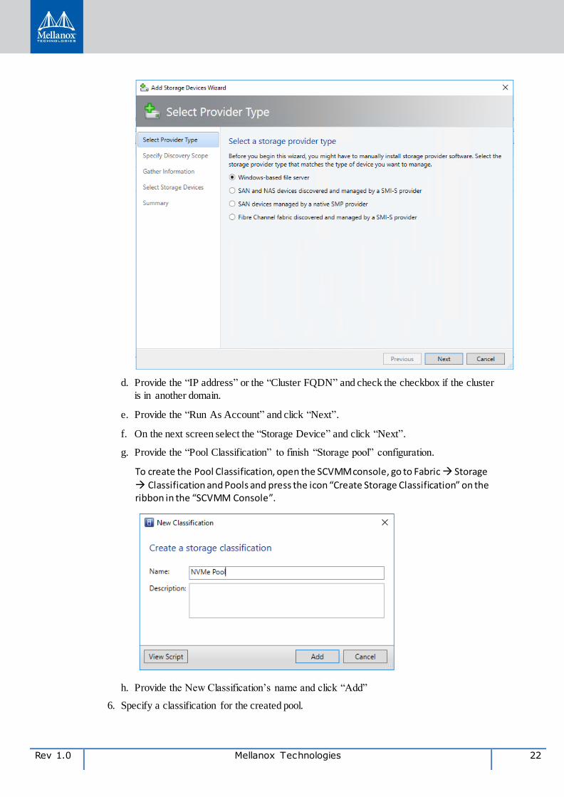
5. Add Storage Provider for Spaces Direct in SCVMM.
a. Open VMM console and navigate to the Fabric workspace.
b. Select Add Resources | Storage Devices and select Windows-based File Server as
shown in the following screenshot.
c. Click Next.
Rev 1.0 Mellanox Technologies 22
d. Provide the “IP address” or the “Cluster FQDN” and check the checkbox if the cluster
is in another domain.
e. Provide the “Run As Account” and click “Next”.
f. On the next screen select the “Storage Device” and click “Next”.
g. Provide the “Pool Classification” to finish “Storage pool” configuration.
To create the Pool Classification, open the SCVMM console, go to Fabric Storage
Classification and Pools and press the icon “Create Storage Classification” on the ribbon in the “SCVMM Console”.
h. Provide the New Classification’s name and click “Add”
6. Specify a classification for the created pool.

23 Mellanox Technologies Rev 1.0
a. Open the VMM console, go to Fabric Storage Arrays
b. Right-click the “Storage Spaces Direct Cluster” created, and then click Manage Pools.
c. Select the storage pool and click Edit.
d. Choose the “Pool classification”
e. Click OK.
7. Create a Cluster Shared Volume.
a. Right-click on the cluster that has been created.
b. Click Properties.
c. Select the Shared Volumes option.
d. Click Add and then follow the steps to create the volume.
Rev 1.0 Mellanox Technologies 24
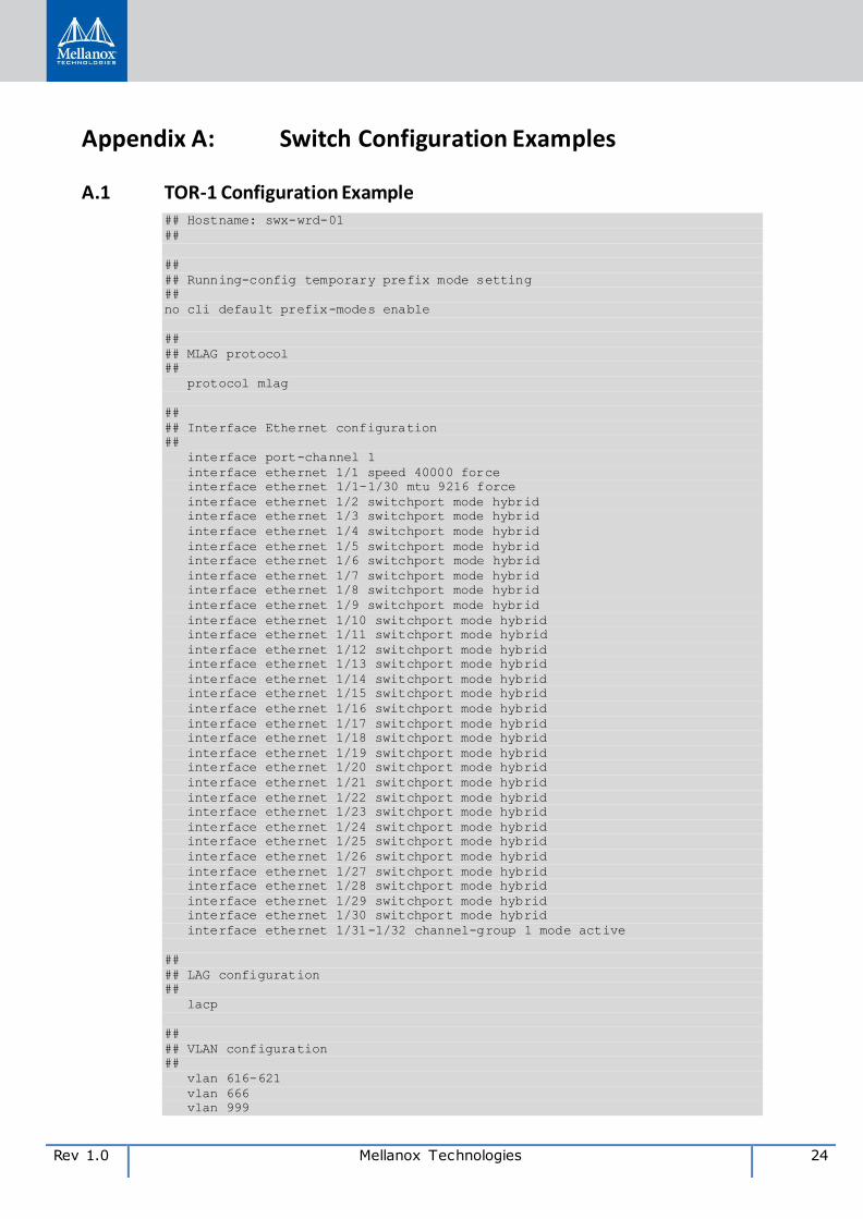
Appendix A: Switch Configuration Examples
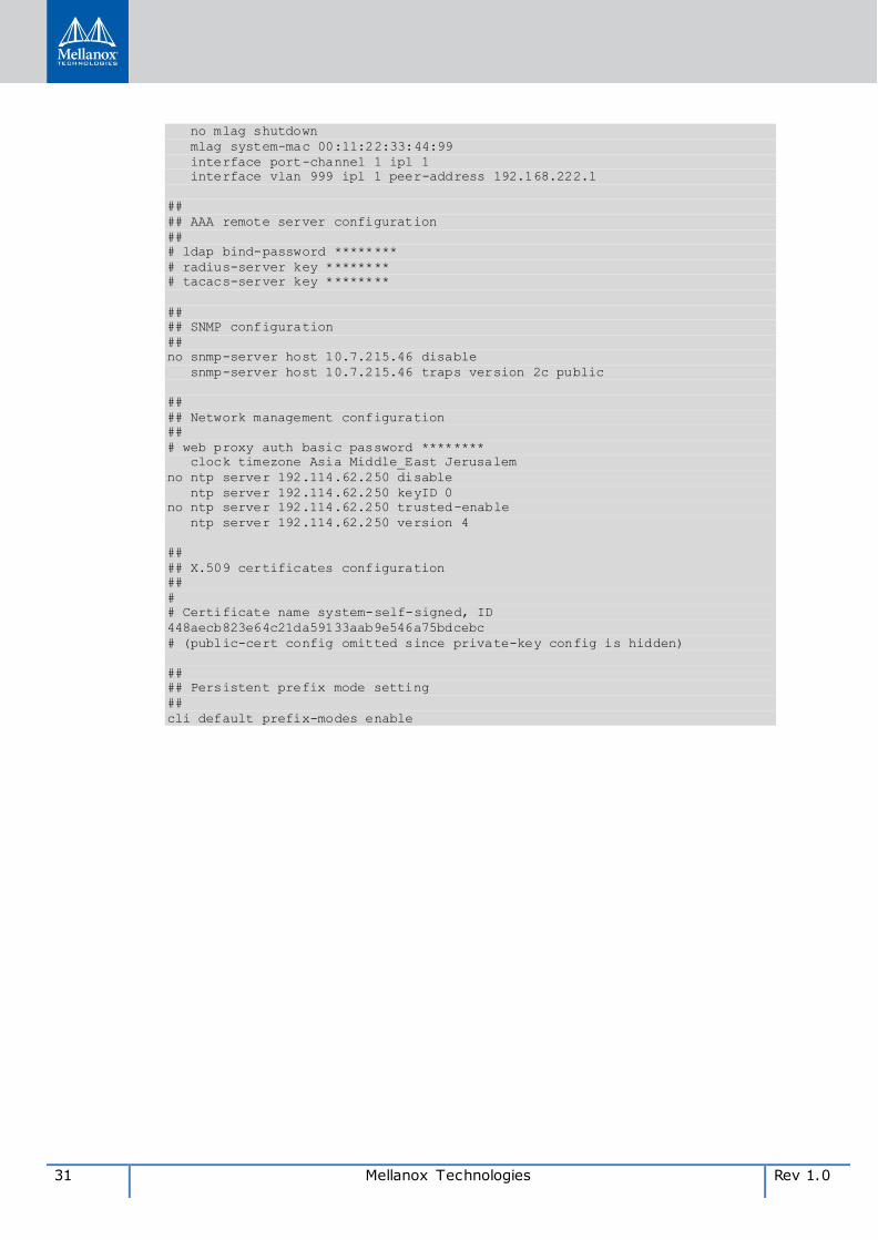
A.1 TOR-1 Configuration Example ## Hostname: swx-wrd-01
##
##
## Running-config temporary prefix mode setting
##
no cli default prefix-modes enable
##
## MLAG protocol
##
protocol mlag
##
## Interface Ethernet configuration
##
interface port-channel 1
interface ethernet 1/1 speed 40000 force
interface ethernet 1/1-1/30 mtu 9216 force
interface ethernet 1/2 switchport mode hybrid
interface ethernet 1/3 switchport mode hybrid
interface ethernet 1/4 switchport mode hybrid
interface ethernet 1/5 switchport mode hybrid
interface ethernet 1/6 switchport mode hybrid
interface ethernet 1/7 switchport mode hybrid
interface ethernet 1/8 switchport mode hybrid
interface ethernet 1/9 switchport mode hybrid
interface ethernet 1/10 switchport mode hybrid
interface ethernet 1/11 switchport mode hybrid
interface ethernet 1/12 switchport mode hybrid
interface ethernet 1/13 switchport mode hybrid
interface ethernet 1/14 switchport mode hybrid
interface ethernet 1/15 switchport mode hybrid
interface ethernet 1/16 switchport mode hybrid
interface ethernet 1/17 switchport mode hybrid
interface ethernet 1/18 switchport mode hybrid
interface ethernet 1/19 switchport mode hybrid
interface ethernet 1/20 switchport mode hybrid
interface ethernet 1/21 switchport mode hybrid
interface ethernet 1/22 switchport mode hybrid
interface ethernet 1/23 switchport mode hybrid
interface ethernet 1/24 switchport mode hybrid
interface ethernet 1/25 switchport mode hybrid
interface ethernet 1/26 switchport mode hybrid
interface ethernet 1/27 switchport mode hybrid
interface ethernet 1/28 switchport mode hybrid
interface ethernet 1/29 switchport mode hybrid
interface ethernet 1/30 switchport mode hybrid
interface ethernet 1/31-1/32 channel-group 1 mode active
##
## LAG configuration
##
lacp
##
## VLAN configuration
##
vlan 616-621
vlan 666
vlan 999

25 Mellanox Technologies Rev 1.0
vlan 616 name "MGMT"
vlan 617 name "Cluster"
vlan 618 name "LiveMigration"
vlan 619 name "Storage"
vlan 621 name "Deploy"
interface ethernet 1/2 switchport access vlan 621
interface ethernet 1/2 switchport hybrid allowed-vlan all
interface ethernet 1/3 switchport access vlan 621
interface ethernet 1/3 switchport hybrid allowed-vlan all
interface ethernet 1/4 switchport access vlan 621
interface ethernet 1/4 switchport hybrid allowed-vlan all
interface ethernet 1/5 switchport access vlan 621
interface ethernet 1/5 switchport hybrid allowed-vlan all
interface ethernet 1/6 switchport access vlan 621
interface ethernet 1/6 switchport hybrid allowed-vlan all
interface ethernet 1/7 switchport access vlan 621
interface ethernet 1/7 switchport hybrid allowed-vlan all
interface ethernet 1/8 switchport access vlan 621
interface ethernet 1/8 switchport hybrid allowed-vlan all
interface ethernet 1/9 switchport access vlan 621
interface ethernet 1/9 switchport hybrid allowed-vlan all
interface ethernet 1/10 switchport access vlan 621
interface ethernet 1/10 switchport hybrid allowed-vlan all
interface ethernet 1/11 switchport access vlan 621
interface ethernet 1/11 switchport hybrid allowed-vlan all
interface ethernet 1/12 switchport access vlan 621
interface ethernet 1/12 switchport hybrid allowed-vlan all
interface ethernet 1/13 switchport access vlan 621
interface ethernet 1/13 switchport hybrid allowed-vlan all
interface ethernet 1/14 switchport access vlan 621
interface ethernet 1/14 switchport hybrid allowed-vlan all
interface ethernet 1/15 switchport access vlan 621
interface ethernet 1/15 switchport hybrid allowed-vlan all
interface ethernet 1/16 switchport access vlan 616
interface ethernet 1/16 switchport hybrid allowed-vlan all
interface ethernet 1/17 switchport access vlan 621
interface ethernet 1/17 switchport hybrid allowed-vlan all
interface ethernet 1/18 switchport access vlan 621
interface ethernet 1/18 switchport hybrid allowed-vlan all
interface ethernet 1/19 switchport access vlan 621
interface ethernet 1/19 switchport hybrid allowed-vlan all
interface ethernet 1/20 switchport access vlan 621
interface ethernet 1/20 switchport hybrid allowed-vlan all
interface ethernet 1/21 switchport access vlan 621
interface ethernet 1/21 switchport hybrid allowed-vlan all
interface ethernet 1/22 switchport access vlan 621
interface ethernet 1/22 switchport hybrid allowed-vlan all
interface ethernet 1/23 switchport access vlan 621
interface ethernet 1/23 switchport hybrid allowed-vlan all
interface ethernet 1/24 switchport access vlan 621
interface ethernet 1/24 switchport hybrid allowed-vlan all
interface ethernet 1/25 switchport access vlan 621
interface ethernet 1/25 switchport hybrid allowed-vlan all
interface ethernet 1/26 switchport access vlan 621
interface ethernet 1/26 switchport hybrid allowed-vlan all
interface ethernet 1/27 switchport access vlan 621
interface ethernet 1/27 switchport hybrid allowed-vlan all
interface ethernet 1/28 switchport access vlan 621
interface ethernet 1/28 switchport hybrid allowed-vlan all
interface ethernet 1/29 switchport access vlan 621
interface ethernet 1/29 switchport hybrid allowed-vlan all
interface ethernet 1/30 switchport access vlan 621
interface ethernet 1/30 switchport hybrid allowed-vlan all
##
## STP configuration
##
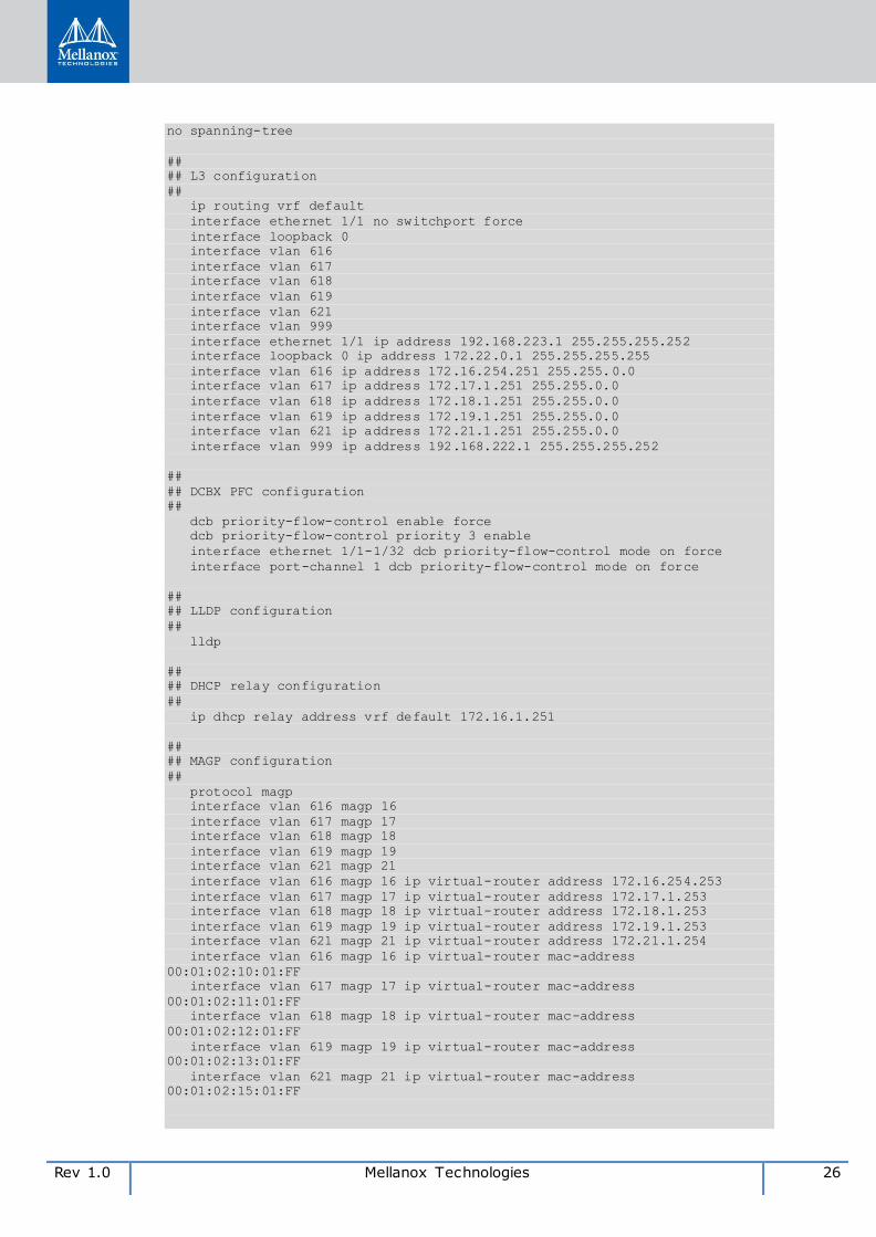
Rev 1.0 Mellanox Technologies 26
no spanning-tree
##
## L3 configuration
##
ip routing vrf default
interface ethernet 1/1 no switchport force
interface loopback 0
interface vlan 616
interface vlan 617
interface vlan 618
interface vlan 619
interface vlan 621
interface vlan 999
interface ethernet 1/1 ip address 192.168.223.1 255.255.255.252
interface loopback 0 ip address 172.22.0.1 255.255.255.255
interface vlan 616 ip address 172.16.254.251 255.255.0.0
interface vlan 617 ip address 172.17.1.251 255.255.0.0
interface vlan 618 ip address 172.18.1.251 255.255.0.0
interface vlan 619 ip address 172.19.1.251 255.255.0.0
interface vlan 621 ip address 172.21.1.251 255.255.0.0
interface vlan 999 ip address 192.168.222.1 255.255.255.252
##
## DCBX PFC configuration
##
dcb priority-flow-control enable force
dcb priority-flow-control priority 3 enable
interface ethernet 1/1-1/32 dcb priority-flow-control mode on force
interface port-channel 1 dcb priority-flow-control mode on force
##
## LLDP configuration
##
lldp
##
## DHCP relay configuration
##
ip dhcp relay address vrf default 172.16.1.251
##
## MAGP configuration
##
protocol magp
interface vlan 616 magp 16
interface vlan 617 magp 17
interface vlan 618 magp 18
interface vlan 619 magp 19
interface vlan 621 magp 21
interface vlan 616 magp 16 ip virtual-router address 172.16.254.253
interface vlan 617 magp 17 ip virtual-router address 172.17.1.253
interface vlan 618 magp 18 ip virtual-router address 172.18.1.253
interface vlan 619 magp 19 ip virtual-router address 172.19.1.253
interface vlan 621 magp 21 ip virtual-router address 172.21.1.254
interface vlan 616 magp 16 ip virtual-router mac-address
00:01:02:10:01:FF
interface vlan 617 magp 17 ip virtual-router mac-address
00:01:02:11:01:FF
interface vlan 618 magp 18 ip virtual-router mac-address
00:01:02:12:01:FF
interface vlan 619 magp 19 ip virtual-router mac-address
00:01:02:13:01:FF
interface vlan 621 magp 21 ip virtual-router mac-address
00:01:02:15:01:FF
27 Mellanox Technologies Rev 1.0
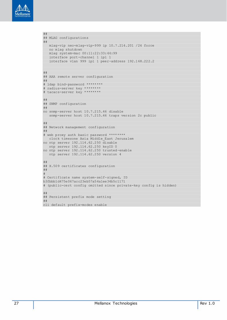
##
## MLAG configurations
##
mlag-vip neo-mlag-vip-999 ip 10.7.214.201 /24 force
no mlag shutdown
mlag system-mac 00:11:22:33:44:99
interface port-channel 1 ipl 1
interface vlan 999 ipl 1 peer-address 192.168.222.2
##
## AAA remote server configuration
##
# ldap bind-password ********
# radius-server key ********
# tacacs-server key ********
##
## SNMP configuration
##
no snmp-server host 10.7.215.46 disable
snmp-server host 10.7.215.46 traps version 2c public
##
## Network management configuration
##
# web proxy auth basic password ********
clock timezone Asia Middle_East Jerusalem
no ntp server 192.114.62.250 disable
ntp server 192.114.62.250 keyID 0
no ntp server 192.114.62.250 trusted-enable
ntp server 192.114.62.250 version 4
##
## X.509 certificates configuration
##
#
# Certificate name system-self-signed, ID
b3fbbb1d475e067acc23eb57a54a1ee34b5c1171
# (public-cert config omitted since private-key config is hidden)
##
## Persistent prefix mode setting
##
cli default prefix-modes enable
Rev 1.0 Mellanox Technologies 28
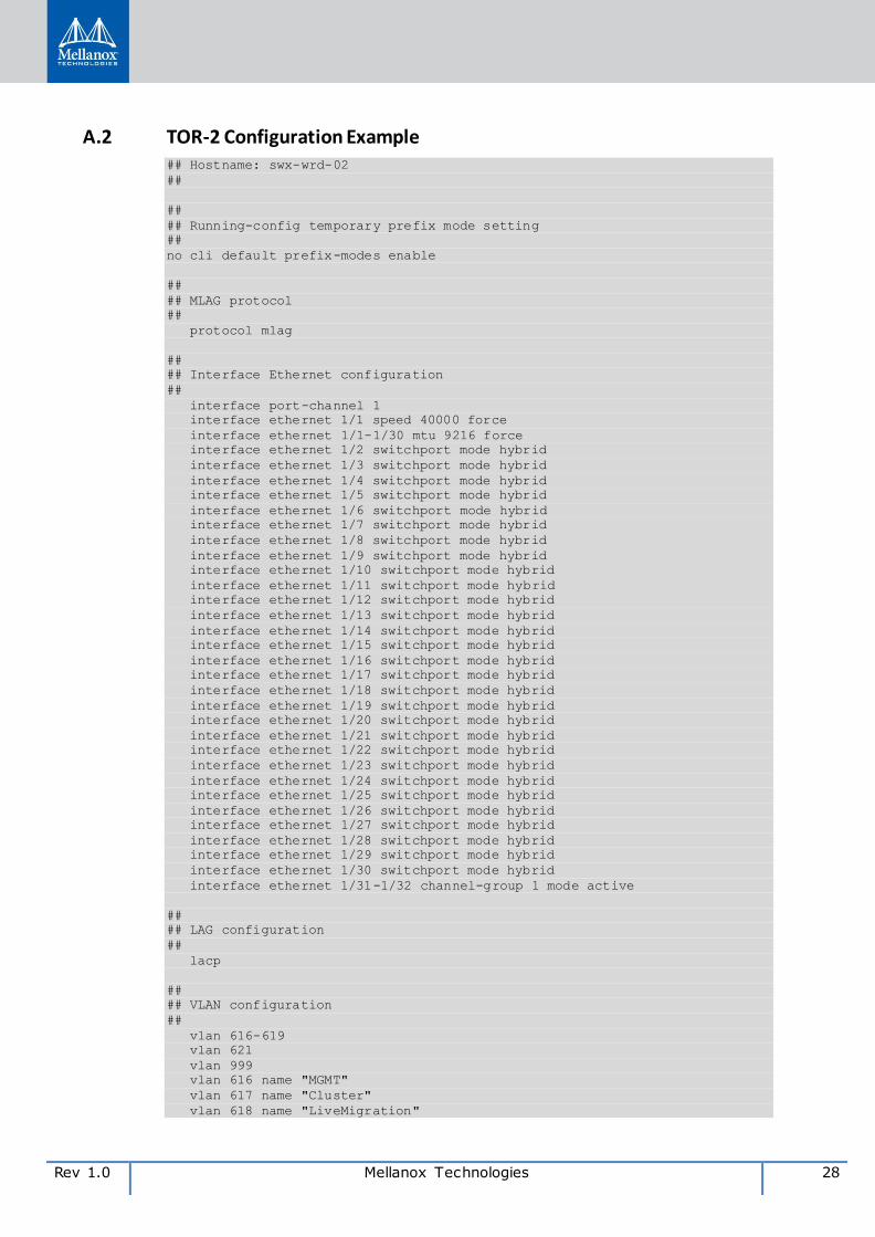
A.2 TOR-2 Configuration Example ## Hostname: swx-wrd-02
##
##
## Running-config temporary prefix mode setting
##
no cli default prefix-modes enable
##
## MLAG protocol
##
protocol mlag
##
## Interface Ethernet configuration
##
interface port-channel 1
interface ethernet 1/1 speed 40000 force
interface ethernet 1/1-1/30 mtu 9216 force
interface ethernet 1/2 switchport mode hybrid
interface ethernet 1/3 switchport mode hybrid
interface ethernet 1/4 switchport mode hybrid
interface ethernet 1/5 switchport mode hybrid
interface ethernet 1/6 switchport mode hybrid
interface ethernet 1/7 switchport mode hybrid
interface ethernet 1/8 switchport mode hybrid
interface ethernet 1/9 switchport mode hybrid
interface ethernet 1/10 switchport mode hybrid
interface ethernet 1/11 switchport mode hybrid
interface ethernet 1/12 switchport mode hybrid
interface ethernet 1/13 switchport mode hybrid
interface ethernet 1/14 switchport mode hybrid
interface ethernet 1/15 switchport mode hybrid
interface ethernet 1/16 switchport mode hybrid
interface ethernet 1/17 switchport mode hybrid
interface ethernet 1/18 switchport mode hybrid
interface ethernet 1/19 switchport mode hybrid
interface ethernet 1/20 switchport mode hybrid
interface ethernet 1/21 switchport mode hybrid
interface ethernet 1/22 switchport mode hybrid
interface ethernet 1/23 switchport mode hybrid
interface ethernet 1/24 switchport mode hybrid
interface ethernet 1/25 switchport mode hybrid
interface ethernet 1/26 switchport mode hybrid
interface ethernet 1/27 switchport mode hybrid
interface ethernet 1/28 switchport mode hybrid
interface ethernet 1/29 switchport mode hybrid
interface ethernet 1/30 switchport mode hybrid
interface ethernet 1/31-1/32 channel-group 1 mode active
##
## LAG configuration
##
lacp
##
## VLAN configuration
##
vlan 616-619
vlan 621
vlan 999
vlan 616 name "MGMT"
vlan 617 name "Cluster"
vlan 618 name "LiveMigration"

29 Mellanox Technologies Rev 1.0
vlan 619 name "Storage"
vlan 621 name "Deploy"
interface ethernet 1/2 switchport access vlan 621
interface ethernet 1/2 switchport hybrid allowed-vlan all
interface ethernet 1/3 switchport access vlan 621
interface ethernet 1/3 switchport hybrid allowed-vlan all
interface ethernet 1/4 switchport access vlan 621
interface ethernet 1/4 switchport hybrid allowed-vlan all
interface ethernet 1/5 switchport access vlan 621
interface ethernet 1/5 switchport hybrid allowed-vlan all
interface ethernet 1/6 switchport access vlan 621
interface ethernet 1/6 switchport hybrid allowed-vlan all
interface ethernet 1/7 switchport access vlan 621
interface ethernet 1/7 switchport hybrid allowed-vlan all
interface ethernet 1/8 switchport access vlan 621
interface ethernet 1/8 switchport hybrid allowed-vlan all
interface ethernet 1/9 switchport access vlan 621
interface ethernet 1/9 switchport hybrid allowed-vlan all
interface ethernet 1/10 switchport access vlan 621
interface ethernet 1/10 switchport hybrid allowed-vlan all
interface ethernet 1/11 switchport access vlan 621
interface ethernet 1/11 switchport hybrid allowed-vlan all
interface ethernet 1/12 switchport access vlan 621
interface ethernet 1/12 switchport hybrid allowed-vlan all
interface ethernet 1/13 switchport access vlan 621
interface ethernet 1/13 switchport hybrid allowed-vlan all
interface ethernet 1/14 switchport access vlan 621
interface ethernet 1/14 switchport hybrid allowed-vlan all
interface ethernet 1/15 switchport access vlan 621
interface ethernet 1/15 switchport hybrid allowed-vlan all
interface ethernet 1/16 switchport access vlan 616
interface ethernet 1/16 switchport hybrid allowed-vlan all
interface ethernet 1/17 switchport access vlan 621
interface ethernet 1/17 switchport hybrid allowed-vlan all
interface ethernet 1/18 switchport access vlan 621
interface ethernet 1/18 switchport hybrid allowed-vlan all
interface ethernet 1/19 switchport access vlan 621
interface ethernet 1/19 switchport hybrid allowed-vlan all
interface ethernet 1/20 switchport access vlan 621
interface ethernet 1/20 switchport hybrid allowed-vlan all
interface ethernet 1/21 switchport access vlan 621
interface ethernet 1/21 switchport hybrid allowed-vlan all
interface ethernet 1/22 switchport access vlan 621
interface ethernet 1/22 switchport hybrid allowed-vlan all
interface ethernet 1/23 switchport access vlan 621
interface ethernet 1/23 switchport hybrid allowed-vlan all
interface ethernet 1/24 switchport access vlan 621
interface ethernet 1/24 switchport hybrid allowed-vlan all
interface ethernet 1/25 switchport access vlan 621
interface ethernet 1/25 switchport hybrid allowed-vlan all
interface ethernet 1/26 switchport access vlan 621
interface ethernet 1/26 switchport hybrid allowed-vlan all
interface ethernet 1/27 switchport access vlan 621
interface ethernet 1/27 switchport hybrid allowed-vlan all
interface ethernet 1/28 switchport access vlan 621
interface ethernet 1/28 switchport hybrid allowed-vlan all
interface ethernet 1/29 switchport access vlan 621
interface ethernet 1/29 switchport hybrid allowed-vlan all
interface ethernet 1/30 switchport access vlan 621
interface ethernet 1/30 switchport hybrid allowed-vlan all
##
## STP configuration
##
no spanning-tree
##
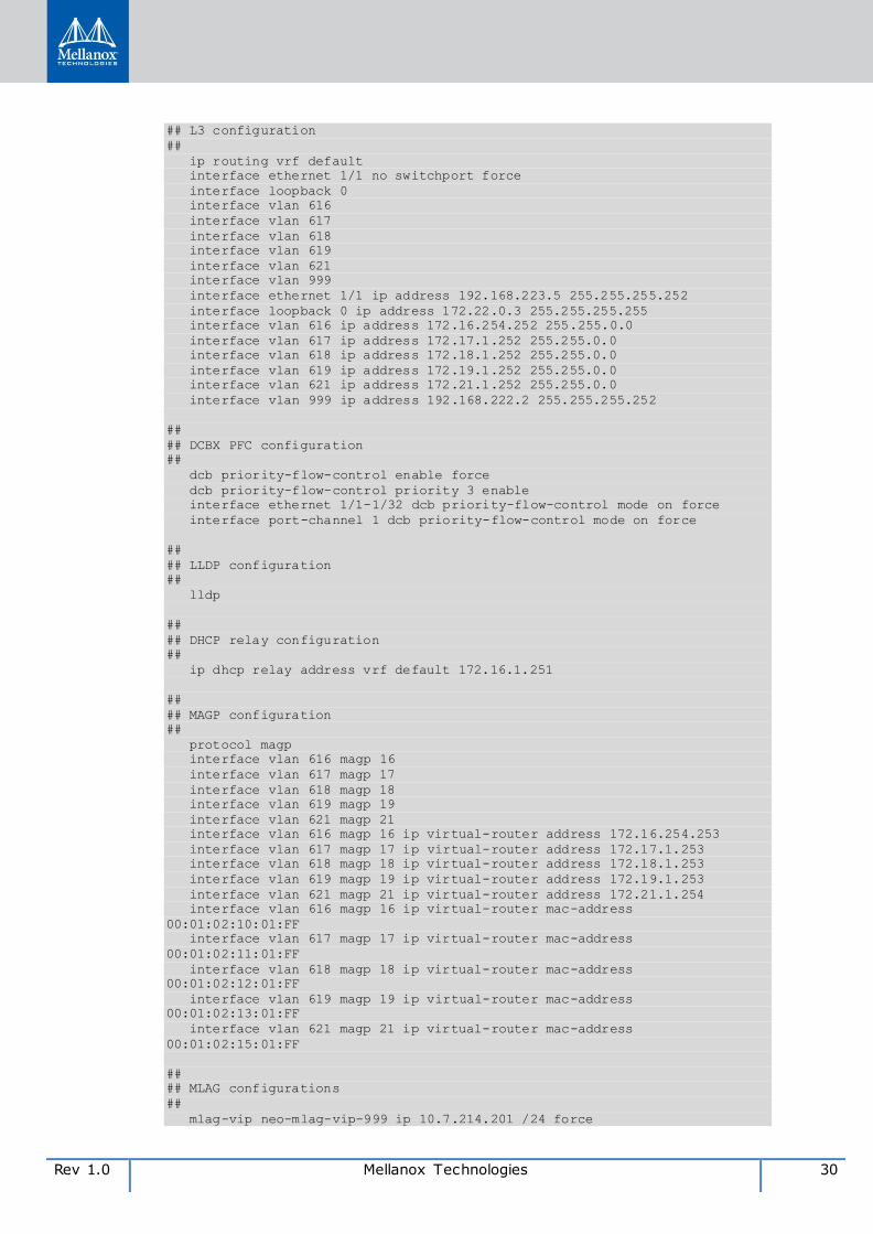
Rev 1.0 Mellanox Technologies 30
## L3 configuration
##
ip routing vrf default
interface ethernet 1/1 no switchport force
interface loopback 0
interface vlan 616
interface vlan 617
interface vlan 618
interface vlan 619
interface vlan 621
interface vlan 999
interface ethernet 1/1 ip address 192.168.223.5 255.255.255.252
interface loopback 0 ip address 172.22.0.3 255.255.255.255
interface vlan 616 ip address 172.16.254.252 255.255.0.0
interface vlan 617 ip address 172.17.1.252 255.255.0.0
interface vlan 618 ip address 172.18.1.252 255.255.0.0
interface vlan 619 ip address 172.19.1.252 255.255.0.0
interface vlan 621 ip address 172.21.1.252 255.255.0.0
interface vlan 999 ip address 192.168.222.2 255.255.255.252
##
## DCBX PFC configuration
##
dcb priority-flow-control enable force
dcb priority-flow-control priority 3 enable
interface ethernet 1/1-1/32 dcb priority-flow-control mode on force
interface port-channel 1 dcb priority-flow-control mode on force
##
## LLDP configuration
##
lldp
##
## DHCP relay configuration
##
ip dhcp relay address vrf default 172.16.1.251
##
## MAGP configuration
##
protocol magp
interface vlan 616 magp 16
interface vlan 617 magp 17
interface vlan 618 magp 18
interface vlan 619 magp 19
interface vlan 621 magp 21
interface vlan 616 magp 16 ip virtual-router address 172.16.254.253
interface vlan 617 magp 17 ip virtual-router address 172.17.1.253
interface vlan 618 magp 18 ip virtual-router address 172.18.1.253
interface vlan 619 magp 19 ip virtual-router address 172.19.1.253
interface vlan 621 magp 21 ip virtual-router address 172.21.1.254
interface vlan 616 magp 16 ip virtual-router mac-address
00:01:02:10:01:FF
interface vlan 617 magp 17 ip virtual-router mac-address
00:01:02:11:01:FF
interface vlan 618 magp 18 ip virtual-router mac-address
00:01:02:12:01:FF
interface vlan 619 magp 19 ip virtual-router mac-address
00:01:02:13:01:FF
interface vlan 621 magp 21 ip virtual-router mac-address
00:01:02:15:01:FF
##
## MLAG configurations
##
mlag-vip neo-mlag-vip-999 ip 10.7.214.201 /24 force
31 Mellanox Technologies Rev 1.0
no mlag shutdown
mlag system-mac 00:11:22:33:44:99
interface port-channel 1 ipl 1
interface vlan 999 ipl 1 peer-address 192.168.222.1
##
## AAA remote server configuration
##
# ldap bind-password ********
# radius-server key ********
# tacacs-server key ********
##
## SNMP configuration
##
no snmp-server host 10.7.215.46 disable
snmp-server host 10.7.215.46 traps version 2c public
##
## Network management configuration
##
# web proxy auth basic password ********
clock timezone Asia Middle_East Jerusalem
no ntp server 192.114.62.250 disable
ntp server 192.114.62.250 keyID 0
no ntp server 192.114.62.250 trusted-enable
ntp server 192.114.62.250 version 4
##
## X.509 certificates configuration
##
#
# Certificate name system-self-signed, ID
448aecb823e64c21da59133aab9e546a75bdcebc
# (public-cert config omitted since private-key config is hidden)
##
## Persistent prefix mode setting
##
cli default prefix-modes enable
Rev 1.0 Mellanox Technologies 32
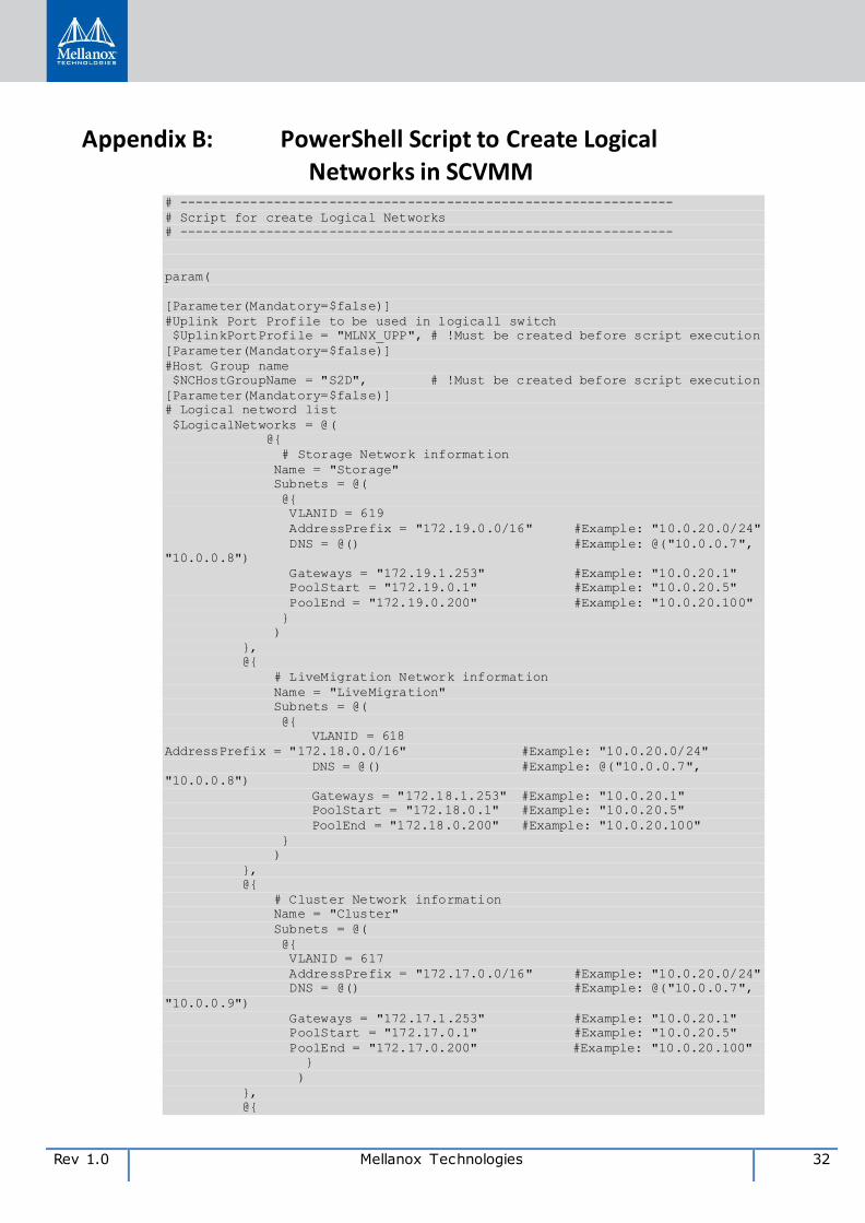
Appendix B: PowerShell Script to Create Logical Networks in SCVMM
# ---------------------------------------------------------------
# Script for create Logical Networks
# ---------------------------------------------------------------
param(
[Parameter(Mandatory=$false)]
#Uplink Port Profile to be used in logicall switch
$UplinkPortProfile = "MLNX_UPP", # !Must be created before script execution
[Parameter(Mandatory=$false)]
#Host Group name
$NCHostGroupName = "S2D", # !Must be created before script execution
[Parameter(Mandatory=$false)]
# Logical netword list
$LogicalNetworks = @(
@{
# Storage Network information
Name = "Storage"
Subnets = @(
@{
VLANID = 619
AddressPrefix = "172.19.0.0/16" #Example: "10.0.20.0/24"
DNS = @() #Example: @("10.0.0.7",
"10.0.0.8")
Gateways = "172.19.1.253" #Example: "10.0.20.1"
PoolStart = "172.19.0.1" #Example: "10.0.20.5"
PoolEnd = "172.19.0.200" #Example: "10.0.20.100"
}
)
},
@{
# LiveMigration Network information
Name = "LiveMigration"
Subnets = @(
@{
VLANID = 618
AddressPrefix = "172.18.0.0/16" #Example: "10.0.20.0/24"
DNS = @() #Example: @("10.0.0.7",
"10.0.0.8")
Gateways = "172.18.1.253" #Example: "10.0.20.1"
PoolStart = "172.18.0.1" #Example: "10.0.20.5"
PoolEnd = "172.18.0.200" #Example: "10.0.20.100"
}
)
},
@{
# Cluster Network information
Name = "Cluster"
Subnets = @(
@{
VLANID = 617
AddressPrefix = "172.17.0.0/16" #Example: "10.0.20.0/24"
DNS = @() #Example: @("10.0.0.7",
"10.0.0.9")
Gateways = "172.17.1.253" #Example: "10.0.20.1"
PoolStart = "172.17.0.1" #Example: "10.0.20.5"
PoolEnd = "172.17.0.200" #Example: "10.0.20.100"
}
)
},
@{
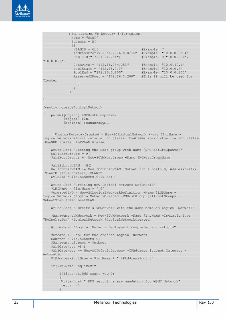
33 Mellanox Technologies Rev 1.0
# Management VM Network information.
Name = "MGMT"
Subnets = @(
@{
VLANID = 616 #Example: 7
AddressPrefix = "172.16.0.0/16" #Example: "10.0.0.0/24"
DNS = @("172.16.1.251") #Example: @("10.0.0.7",
"10.0.0.9")
Gateways = "172.16.254.253" #Example: "10.0.40.1"
PoolStart = "172.16.0.1" #Example: "10.0.0.5"
PoolEnd = "172.16.0.200" #Example: "10.0.0.100"
ReservedIPset = "172.16.0.200" #This IP will be used for
Cluster
}
)
}
)
)
function createLogicalNetwork
{
param([Object] $NCHostGroupName,
[object] $ln,
[boolean] $ManagedByNC
)
$LogicalNetworkCreated = New-SCLogicalNetwork -Name $ln.Name -
LogicalNetworkDefinitionIsolation $false -EnableNetworkVirtualization $false
-UseGRE $false -IsPVLAN $false
Write-Host "Getting the Host group with Name [$NCHostGroupName]"
$allHostGroups = @()
$allHostGroups += Get-SCVMHostGroup -Name $NCHostGroupName
$allSubnetVLAN = @()
$allSubnetVLAN += New-SCSubnetVLAN -Subnet $ln.subnets[0].AddressPrefix
-VLanID $ln.subnets[0].VLANID
$VLANId = $ln.subnets[0].VLANID
Write-Host "Creating new Logical Network Definition"
$LNDName = $ln.Name + "_0"
$createdLND = New-SCLogicalNetworkDefinition -Name $LNDName -
LogicalNetwork $LogicalNetworkCreated -VMHostGroup $allHostGroups -
SubnetVLan $allSubnetVLAN
Write-Host " create a VMNetwork with the same name as Logical Network"
$ManagementVMNetwork = New-SCVMNetwork -Name $ln.Name -IsolationType
"NoIsolation" -LogicalNetwork $LogicalNetworkCreated
Write-Host "Logical Network Deployment completed succssfully"
#Create IP Pool for the created Logical Network
$subnet = $ln.subnets[0]
$ManagementSubnet = $subnet
$allGateways =@()
$allGateways += New-SCDefaultGateway -IPAddress $subnet.Gateways -
Automatic
$IPAddressPoolName = $ln.Name + "_IPAddressPool_0"
if($ln.Name -eq "MGMT")
{
if($subnet.DNS.count -eq 0)
{
Write-Host " DNS setttings are mandatory for MGMT Network"
return -1
}
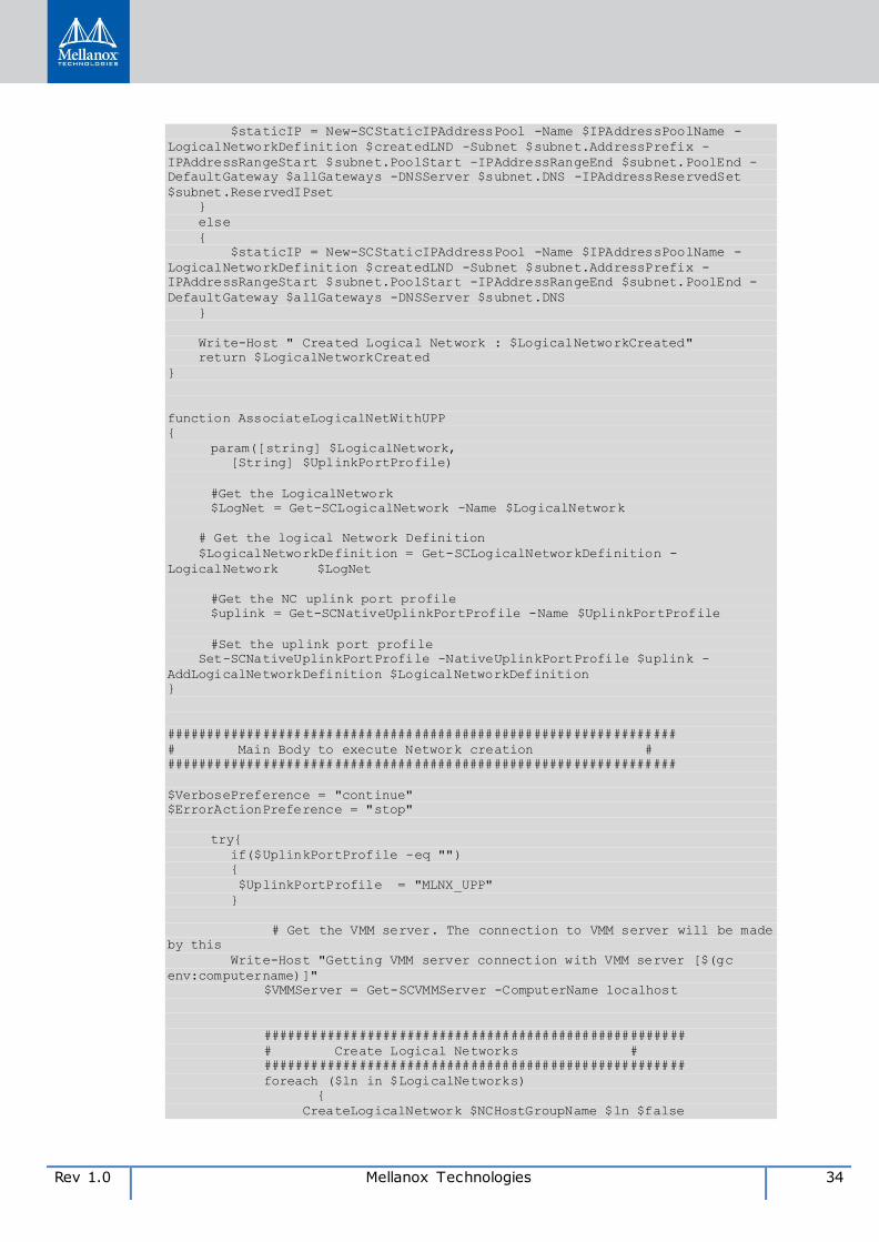
Rev 1.0 Mellanox Technologies 34
$staticIP = New-SCStaticIPAddressPool -Name $IPAddressPoolName -
LogicalNetworkDefinition $createdLND -Subnet $subnet.AddressPrefix -
IPAddressRangeStart $subnet.PoolStart -IPAddressRangeEnd $subnet.PoolEnd -
DefaultGateway $allGateways -DNSServer $subnet.DNS -IPAddressReservedSet
$subnet.ReservedIPset
}
else
{
$staticIP = New-SCStaticIPAddressPool -Name $IPAddressPoolName -
LogicalNetworkDefinition $createdLND -Subnet $subnet.AddressPrefix -
IPAddressRangeStart $subnet.PoolStart -IPAddressRangeEnd $subnet.PoolEnd -
DefaultGateway $allGateways -DNSServer $subnet.DNS
}
Write-Host " Created Logical Network : $LogicalNetworkCreated"
return $LogicalNetworkCreated
}
function AssociateLogicalNetWithUPP
{
param([string] $LogicalNetwork,
[String] $UplinkPortProfile)
#Get the LogicalNetwork
$LogNet = Get-SCLogicalNetwork -Name $LogicalNetwork
# Get the logical Network Definition
$LogicalNetworkDefinition = Get-SCLogicalNetworkDefinition -
LogicalNetwork $LogNet
#Get the NC uplink port profile
$uplink = Get-SCNativeUplinkPortProfile -Name $UplinkPortProfile
#Set the uplink port profile
Set-SCNativeUplinkPortProfile -NativeUplinkPortProfile $uplink -
AddLogicalNetworkDefinition $LogicalNetworkDefinition
}
################################################################
# Main Body to execute Network creation #
################################################################
$VerbosePreference = "continue"
$ErrorActionPreference = "stop"
try{
if($UplinkPortProfile -eq "")
{
$UplinkPortProfile = "MLNX_UPP"
}
# Get the VMM server. The connection to VMM server will be made
by this
Write-Host "Getting VMM server connection with VMM server [$(gc
env:computername)]"
$VMMServer = Get-SCVMMServer -ComputerName localhost
#####################################################
# Create Logical Networks #
#####################################################
foreach ($ln in $LogicalNetworks)
{
CreateLogicalNetwork $NCHostGroupName $ln $false
35 Mellanox Technologies Rev 1.0
AssociateLogicalNetWithUPP $ln.Name $UplinkPortProfile
Write-Host " Logical Network creation
succeeded -"$ln.Name
}
}
catch
{
Write-Host " There is some Failure. Cleaning up the system to get
in previous state..."
#cleanup the setup
}
Rev 1.0 Mellanox Technologies 36
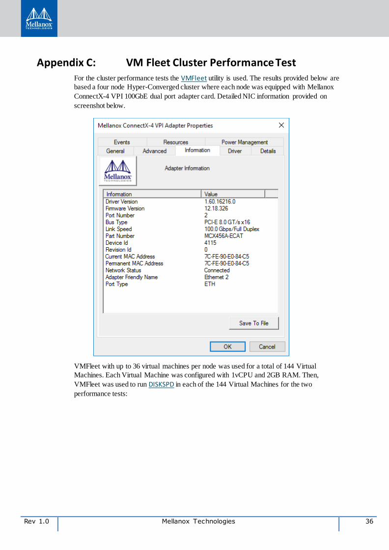
Appendix C: VM Fleet Cluster Performance Test For the cluster performance tests the VMFleet utility is used. The results provided below are
based a four node Hyper-Converged cluster where each node was equipped with Mellanox
ConnectX-4 VPI 100GbE dual port adapter card. Detailed NIC information provided on
screenshot below.
VMFleet with up to 36 virtual machines per node was used for a total of 144 Virtual
Machines. Each Virtual Machine was configured with 1vCPU and 2GB RAM. Then,
VMFleet was used to run DISKSPD in each of the 144 Virtual Machines for the two
performance tests:
37 Mellanox Technologies Rev 1.0
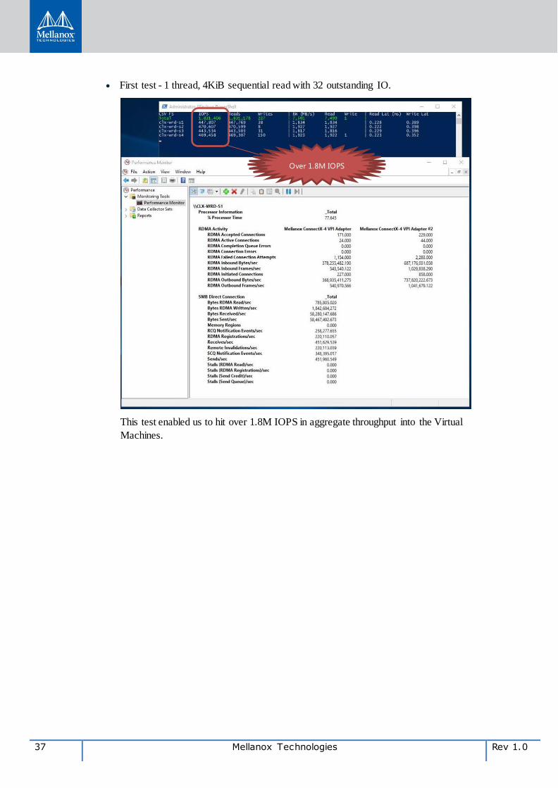
First test - 1 thread, 4KiB sequential read with 32 outstanding IO.
This test enabled us to hit over 1.8M IOPS in aggregate throughput into the Virtual
Machines.
Over 1.8M IOPS
Rev 1.0 Mellanox Technologies 38
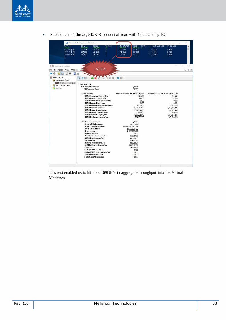
Second test - 1 thread, 512KiB sequential read with 4 outstanding IO.
This test enabled us to hit about 69GB/s in aggregate throughput into the Virtual
Machines.
~69GB/s


![[PLCUG] Hyper converged - overview (PL)](https://img.pdfslide.net/doc/110x75/58e540b71a28ab3a468b468f/plcug-hyper-converged-overview-pl.jpg)