Embed Size (px)
Citation preview
NASA/TM-2002-210723
Wing Torsional Stiffness Tests of the Active Aeroelastic Wing F/A-18 Airplane
William A. Lokos, Candida D. Olney, Natalie D. Crawford, Rick Stauf, and Eric Y. ReichenbachNASA Dryden Flight Research CenterEdwards, California
May 2002

The NASA STI Program Office…in Profile
Since its founding, NASA has been dedicatedto the advancement of aeronautics and space science. The NASA Scientific and Technical Information (STI) Program Office plays a keypart in helping NASA maintain thisimportant role.
The NASA STI Program Office is operated byLangley Research Center, the lead center forNASA’s scientific and technical information.The NASA STI Program Office provides access to the NASA STI Database, the largest collectionof aeronautical and space science STI in theworld. The Program Office is also NASA’s institutional mechanism for disseminating theresults of its research and development activities. These results are published by NASA in theNASA STI Report Series, which includes the following report types:
• TECHNICAL PUBLICATION. Reports of completed research or a major significantphase of research that present the results of NASA programs and include extensive dataor theoretical analysis. Includes compilations of significant scientific and technical data and information deemed to be of continuing reference value. NASA’s counterpart of peer-reviewed formal professional papers but has less stringent limitations on manuscriptlength and extent of graphic presentations.
• TECHNICAL MEMORANDUM. Scientificand technical findings that are preliminary orof specialized interest, e.g., quick releasereports, working papers, and bibliographiesthat contain minimal annotation. Does notcontain extensive analysis.
• CONTRACTOR REPORT. Scientific and technical findings by NASA-sponsored contractors and grantees.
• CONFERENCE PUBLICATION. Collected papers from scientific andtechnical conferences, symposia, seminars,or other meetings sponsored or cosponsoredby NASA.
• SPECIAL PUBLICATION. Scientific,technical, or historical information fromNASA programs, projects, and mission,often concerned with subjects havingsubstantial public interest.
• TECHNICAL TRANSLATION. English- language translations of foreign scientific and technical material pertinent toNASA’s mission.
Specialized services that complement the STIProgram Office’s diverse offerings include creating custom thesauri, building customizeddatabases, organizing and publishing researchresults…even providing videos.
For more information about the NASA STIProgram Office, see the following:
• Access the NASA STI Program Home Pageat
http://www.sti.nasa.gov
• E-mail your question via the Internet to [email protected]
• Fax your question to the NASA Access HelpDesk at (301) 621-0134
• Telephone the NASA Access Help Desk at(301) 621-0390
• Write to:NASA Access Help DeskNASA Center for AeroSpace Information7121 Standard DriveHanover, MD 21076-1320
NASA/TM-2002-210723
Wing Torsional Stiffness Tests of the Active Aeroelastic Wing F/A-18 Airplane
William A. Lokos, Candida D. Olney, Natalie D. Crawford, Rick Stauf, and Eric Y. ReichenbachNASA Dryden Flight Research CenterEdwards, California
May 2002
National Aeronautics andSpace Administration
Dryden Flight Research CenterEdwards, California 93523-0273
NOTICE
Use of trade names or names of manufacturers in this document does not constitute an official endorsementof such products or manufacturers, either expressed or implied, by the National Aeronautics andSpace Administration.
Available from the following:
NASA Center for AeroSpace Information (CASI) National Technical Information Service (NTIS)7121 Standard Drive 5285 Port Royal RoadHanover, MD 21076-1320 Springfield, VA 22161-2171(301) 621-0390 (703) 487-4650
WING TORSIONAL STIFFNESS TESTS OF THE ACTIVE AEROELASTIC WING F/A-18 AIRPLANE
William A. Lokos*, Candida D. Olney†, and Natalie D. Crawford‡
NASA Dryden Flight Research CenterEdwards, California
Rick Stauf§
Spiral Technology Inc.Lancaster, California
Eric Y. Reichenbach¶
The Boeing CompanySt. Louis, Missouri
Abstract
The left wing of the Active Aeroelastic Wing (AAW)F/A-18 airplane has been ground–load-tested toquantify its torsional stiffness. The test has beenperformed at the NASA Dryden Flight ResearchCenter in November 1996, and again in April 2001after a wing skin modification was performed. Theprimary objectives of these tests were to characterizethe wing behavior before the first flight, and provide abefore-and-after measurement of the torsionalstiffness. Two streamwise load couples have beenapplied. The wing skin modification is shown to havemore torsional flexibility than the originalconfiguration has. Additionally, structural hysteresis isshown to be reduced by the skin modification. Datacomparisons show good repeatability between thetests.
Nomenclature
AAW Active Aeroelastic Wing
FEM finite-element model
x, y, z Cartesian coordinates
1American Institute of Aero
*Aerospace Engineer†Aerospace Engineer‡Aerospace Engineer, Member§Structural Flight Test Engineer¶Aerospace Engineer, Member
Copyright 2002 by the American Institute of Aeronautics andAstronautics, Inc. No copyright is asserted in the United States underTitle 17, U.S. Code. The U.S. Government has a royalty-free licenseto exercise all rights under the copyright claimed herein forGovernmental purposes. All other rights are reserved by the copyrightowner.
Introduction
For more than a decade, wing torsional flexibility hasbeen proposed to aeroelastically enhance the rollmaneuverability of high-performance aircraft.1
Although aileron reversal–related aeroelastic controlbehavior has always been avoided, even if it meantadditional structural weight; when the behavior isincorporated as a preprogrammed control mode, somesignificant benefits might be reaped. When the mode isdesigned into a new airframe, reduced weight, increasedmaneuverability, and other advantages can beexploited.2
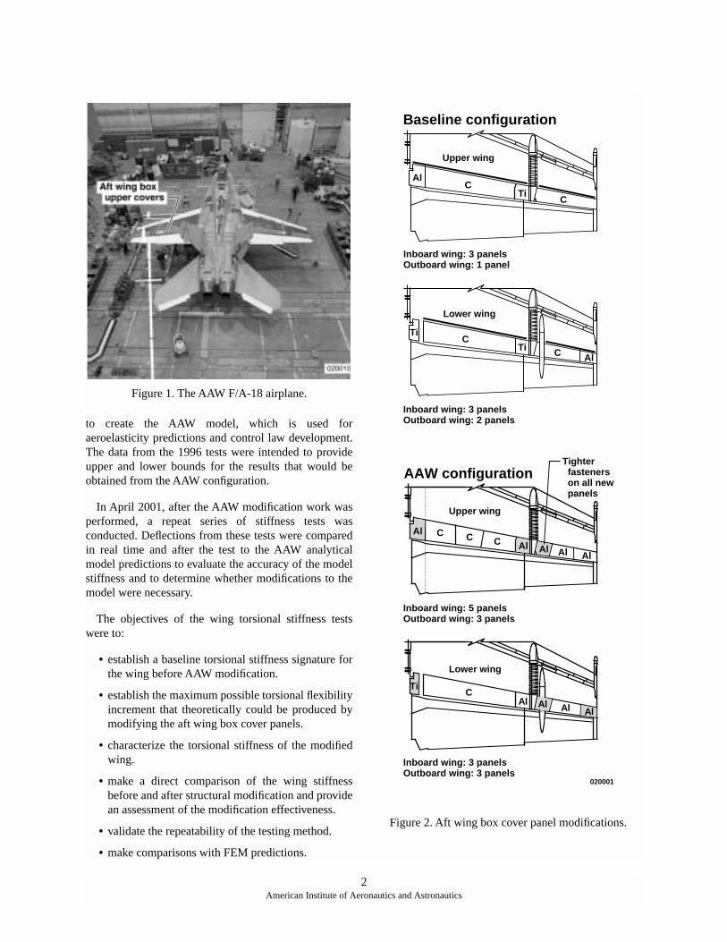
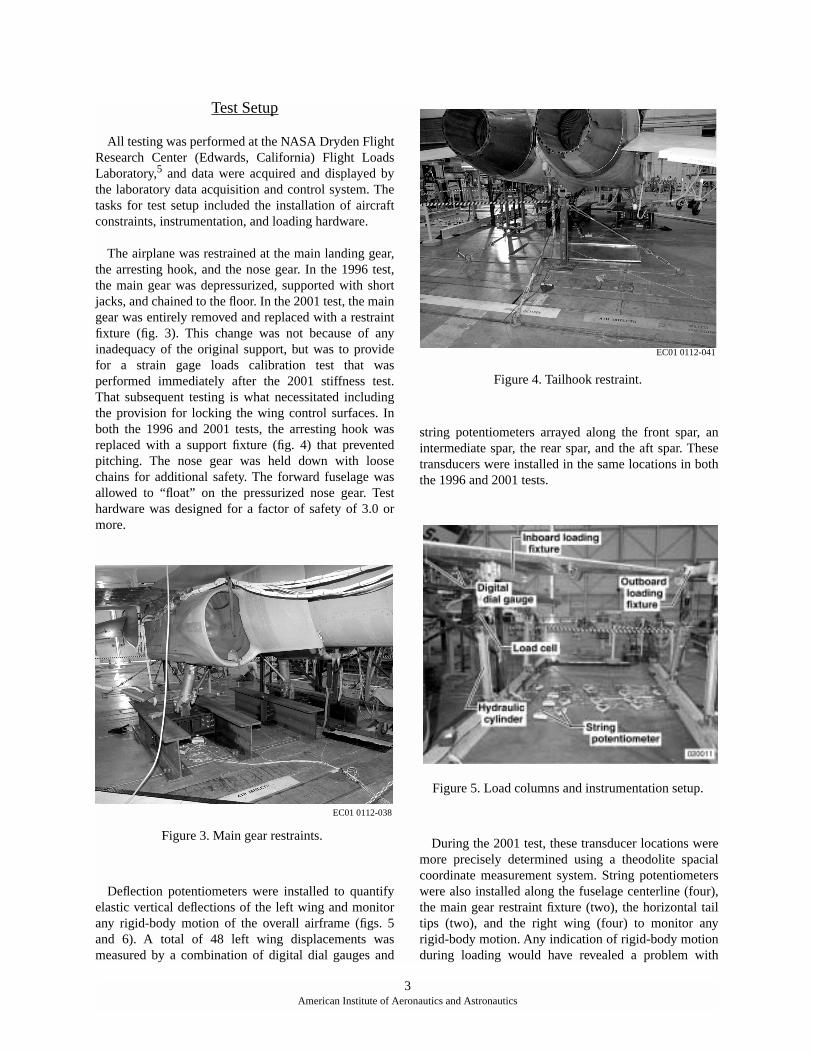
A NASA F/A-18 airplane (fig. 1) has been structurallymodified to support this type of research.3 The coverpanels on the aft wing box were replaced with moreflexible panels to replicate the stiffness of the originalpreproduction F/A-18 aircraft. Figure 2 showsconfigurations for the aft wing box cover panels beforeand after the Active Aeroelastic Wing (AAW)modification. The first preproduction version of the F/A-18 aircraft was found to have the potential for aileronreversal within its performance envelope, which makesthe configuration ideal for demonstrating AAWtechnology. Production F/A-18 aircraft were built withstiffer wings to preclude this tendency and increase rollperformance through the use of conventional wingcontrol surfaces and asymmetric stabilator.
Early in the AAW project, structural testing wasanticipated to have an important role in accomplishingproject objectives.4 In November 1996, prior to theAAW modification, the wing was tested to quantify itsbaseline torsional stiffness. These tests were used tomodify the baseline F/A-18 finite-element model (FEM)
nautics and Astronautics
to create the AAW model, which is used foraeroelasticity predictions and control law development.The data from the 1996 tests were intended to provideupper and lower bounds for the results that would beobtained from the AAW configuration.
In April 2001, after the AAW modification work wasperformed, a repeat series of stiffness tests wasconducted. Deflections from these tests were comparedin real time and after the test to the AAW analyticalmodel predictions to evaluate the accuracy of the modelstiffness and to determine whether modifications to themodel were necessary.
The objectives of the wing torsional stiffness testswere to:
• establish a baseline torsional stiffness signature forthe wing before AAW modification.
• establish the maximum possible torsional flexibilityincrement that theoretically could be produced bymodifying the aft wing box cover panels.
• characterize the torsional stiffness of the modifiedwing.
• make a direct comparison of the wing stiffnessbefore and after structural modification and providean assessment of the modification effectiveness.
• validate the repeatability of the testing method.
• make comparisons with FEM predictions.
Figure 1. The AAW F/A-18 airplane.
AAW configuration
Upper wing
C
Al
C
AlC
Baseline configuration
AlC
CTi
Upper wing
TiC
AlCTi
Al
AlAl
CAl
Al
Ti
AlAl
Inboard wing: 3 panelsOutboard wing: 2 panels
Lower wing
Lower wing
020001
Inboard wing: 3 panelsOutboard wing: 1 panel
Tighter fasteners on all new panels
Inboard wing: 5 panelsOutboard wing: 3 panels
Inboard wing: 3 panelsOutboard wing: 3 panels
Figure 2. Aft wing box cover panel modifications.
2American Institute of Aeronautics and Astronautics
Test Setup
All testing was performed at the NASA Dryden FlightResearch Center (Edwards, California) Flight LoadsLaboratory,5 and data were acquired and displayed bythe laboratory data acquisition and control system. Thetasks for test setup included the installation of aircraftconstraints, instrumentation, and loading hardware.
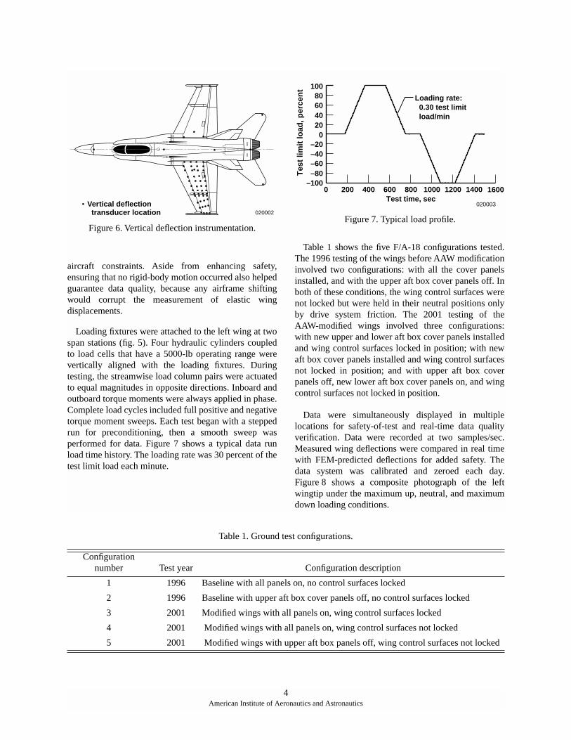
The airplane was restrained at the main landing gear,the arresting hook, and the nose gear. In the 1996 test,the main gear was depressurized, supported with shortjacks, and chained to the floor. In the 2001 test, the maingear was entirely removed and replaced with a restraintfixture (fig. 3). This change was not because of anyinadequacy of the original support, but was to providefor a strain gage loads calibration test that wasperformed immediately after the 2001 stiffness test.That subsequent testing is what necessitated includingthe provision for locking the wing control surfaces. Inboth the 1996 and 2001 tests, the arresting hook wasreplaced with a support fixture (fig. 4) that preventedpitching. The nose gear was held down with loosechains for additional safety. The forward fuselage wasallowed to “float” on the pressurized nose gear. Testhardware was designed for a factor of safety of 3.0 ormore.
Deflection potentiometers were installed to quantifyelastic vertical deflections of the left wing and monitorany rigid-body motion of the overall airframe (figs. 5and 6). A total of 48 left wing displacements wasmeasured by a combination of digital dial gauges and
string potentiometers arrayed along the front spar, anintermediate spar, the rear spar, and the aft spar. Thesetransducers were installed in the same locations in boththe 1996 and 2001 tests.
During the 2001 test, these transducer locations weremore precisely determined using a theodolite spacialcoordinate measurement system. String potentiometerswere also installed along the fuselage centerline (four),the main gear restraint fixture (two), the horizontal tailtips (two), and the right wing (four) to monitor anyrigid-body motion. Any indication of rigid-body motionduring loading would have revealed a problem with
EC01 0112-038
Figure 3. Main gear restraints.
EC01 0112-041
Figure 4. Tailhook restraint.
Figure 5. Load columns and instrumentation setup.
3American Institute of Aeronautics and Astronautics
aircraft constraints. Aside from enhancing safety,ensuring that no rigid-body motion occurred also helpedguarantee data quality, because any airframe shiftingwould corrupt the measurement of elastic wingdisplacements.
Loading fixtures were attached to the left wing at twospan stations (fig. 5). Four hydraulic cylinders coupledto load cells that have a 5000-lb operating range werevertically aligned with the loading fixtures. Duringtesting, the streamwise load column pairs were actuatedto equal magnitudes in opposite directions. Inboard andoutboard torque moments were always applied in phase.Complete load cycles included full positive and negativetorque moment sweeps. Each test began with a steppedrun for preconditioning, then a smooth sweep wasperformed for data. Figure 7 shows a typical data runload time history. The loading rate was 30 percent of thetest limit load each minute.
Table 1 shows the five F/A-18 configurations tested.The 1996 testing of the wings before AAW modificationinvolved two configurations: with all the cover panelsinstalled, and with the upper aft box cover panels off. Inboth of these conditions, the wing control surfaces werenot locked but were held in their neutral positions onlyby drive system friction. The 2001 testing of theAAW-modified wings involved three configurations:with new upper and lower aft box cover panels installedand wing control surfaces locked in position; with newaft box cover panels installed and wing control surfacesnot locked in position; and with upper aft box coverpanels off, new lower aft box cover panels on, and wingcontrol surfaces not locked in position.
Data were simultaneously displayed in multiplelocations for safety-of-test and real-time data qualityverification. Data were recorded at two samples/sec.Measured wing deflections were compared in real timewith FEM-predicted deflections for added safety. Thedata system was calibrated and zeroed each day.Figure 8 shows a composite photograph of the leftwingtip under the maximum up, neutral, and maximumdown loading conditions.
020002Vertical deflection transducer location
Figure 6. Vertical deflection instrumentation.
100
0
Loading rate: 0.30 test limit load/min
806040200
–20–40–60–80
–100
Tes
t lim
it lo
ad, p
erce
nt
200 400 800Test time, sec
600 1000 1200 1400 1600
020003
Figure 7. Typical load profile.
4American Institute of Aeronautics and Astronautics
Table 1. Ground test configurations.
Configurationnumber Test year Configuration description
1 1996 Baseline with all panels on, no control surfaces locked
2 1996 Baseline with upper aft box cover panels off, no control surfaces locked
3 2001 Modified wings with all panels on, wing control surfaces locked
4 2001 Modified wings with all panels on, wing control surfaces not locked
5 2001 Modified wings with upper aft box panels off, wing control surfaces not locked
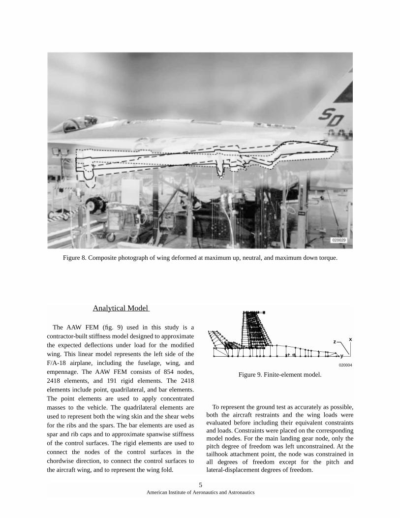
Figure 8. Composite photograph of wing deformed at maximum up, neutral, and maximum down torque.
Analytical Model
The AAW FEM (fig. 9) used in this study is acontractor-built stiffness model designed to approximatethe expected deflections under load for the modifiedwing. This linear model represents the left side of theF/A-18 airplane, including the fuselage, wing, andempennage. The AAW FEM consists of 854 nodes,2418 elements, and 191 rigid elements. The 2418elements include point, quadrilateral, and bar elements.The point elements are used to apply concentratedmasses to the vehicle. The quadrilateral elements areused to represent both the wing skin and the shear websfor the ribs and the spars. The bar elements are used asspar and rib caps and to approximate spanwise stiffnessof the control surfaces. The rigid elements are used toconnect the nodes of the control surfaces in thechordwise direction, to connect the control surfaces tothe aircraft wing, and to represent the wing fold.
To represent the ground test as accurately as possible,both the aircraft restraints and the wing loads wereevaluated before including their equivalent constraintsand loads. Constraints were placed on the correspondingmodel nodes. For the main landing gear node, only thepitch degree of freedom was left unconstrained. At thetailhook attachment point, the node was constrained inall degrees of freedom except for the pitch andlateral-displacement degrees of freedom.
z
020004
x
y
Figure 9. Finite-element model.
5American Institute of Aeronautics and Astronautics
The load couples, which were applied to the model,also had to be functionally equivalent to those placed onthe vehicle. Because the nodes used in the loads modelwere not exactly in the same place as the fixtureattachment points on the vehicle, the load values used inthe model had to be modified so that the resulting rootbending and torque were the same as those applied tothe vehicle during the ground test. The AAWFEM-predicted deflections then were compared to thosedeflections obtained during the ground test.
Data Analysis Method
To calculate the elastic twist increment (as measuredat the wingtip) for each applied torque moment, thefollowing steps were performed for each testconfiguration:
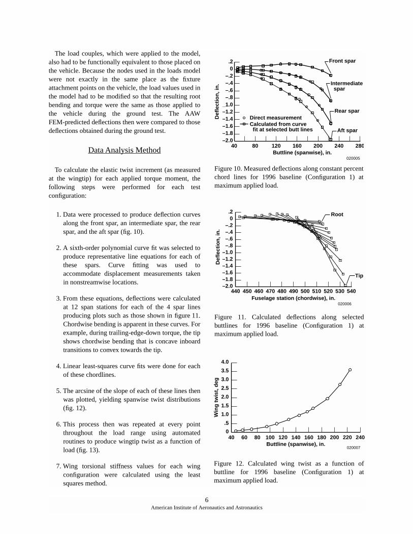
1. Data were processed to produce deflection curvesalong the front spar, an intermediate spar, the rearspar, and the aft spar (fig. 10).
2. A sixth-order polynomial curve fit was selected toproduce representative line equations for each ofthese spars. Curve fitting was used toaccommodate displacement measurements takenin nonstreamwise locations.
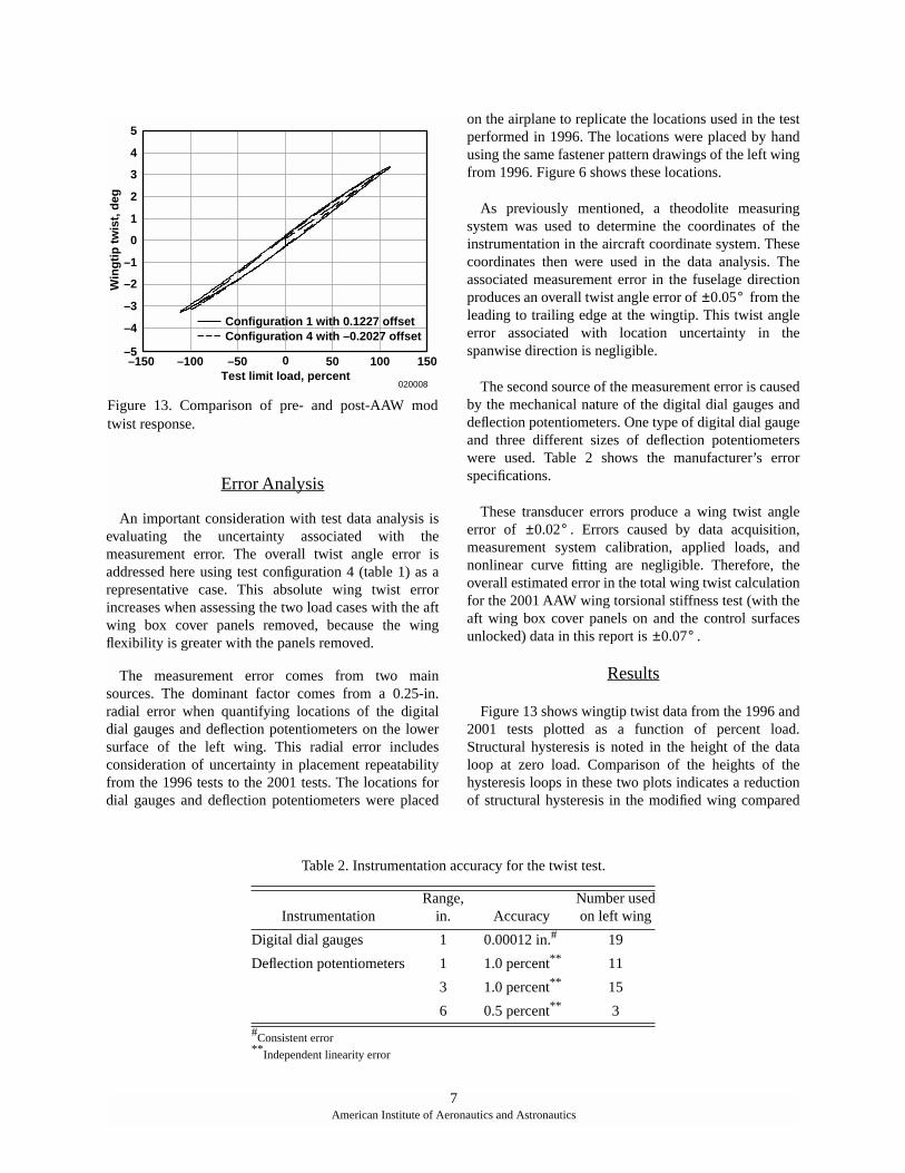
3. From these equations, deflections were calculatedat 12 span stations for each of the 4 spar linesproducing plots such as those shown in figure 11.Chordwise bending is apparent in these curves. Forexample, during trailing-edge-down torque, the tipshows chordwise bending that is concave inboardtransitions to convex towards the tip.
4. Linear least-squares curve fits were done for eachof these chordlines.
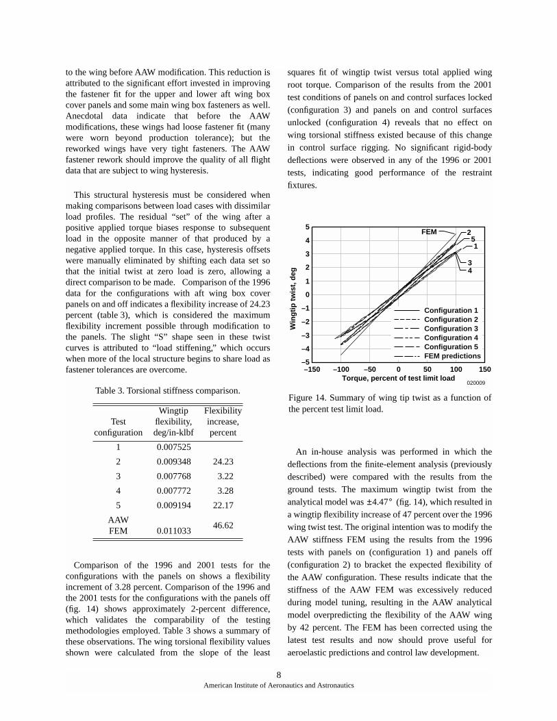
5. The arcsine of the slope of each of these lines thenwas plotted, yielding spanwise twist distributions(fig. 12).
6. This process then was repeated at every pointthroughout the load range using automatedroutines to produce wingtip twist as a function ofload (fig. 13).
7. Wing torsional stiffness values for each wingconfiguration were calculated using the leastsquares method.
.2
Def
lect
ion
, in
.
Buttline (spanwise), in.40
Intermediate spar
Rear spar
Aft spar
Direct measurementCalculated from curve fit at selected butt lines
80 120 160 200 240 280
020005
Front spar0
–.2–.4–.6–.8
_1.0–1.2–1.4–1.6–1.8–2.0
Figure 10. Measured deflections along constant percentchord lines for 1996 baseline (Configuration 1) atmaximum applied load.
.2D
efle
ctio
n, i
n.
440Fuselage station (chordwise), in.
Tip
Root0
–.2–.4–.6–.8
–1.0–1.2–1.4–1.6–1.8–2.0
450 460 470 480 490 500 510 520 530 540
020006
Figure 11. Calculated deflections along selectedbuttlines for 1996 baseline (Configuration 1) atmaximum applied load.
4.0
Win
g t
wis
t, d
eg
240220
020007
200180160140120100806040Buttline (spanwise), in.
3.5
3.0
2.5
2.0
1.5
1.0
.5
0
Figure 12. Calculated wing twist as a function ofbuttline for 1996 baseline (Configuration 1) atmaximum applied load.
6American Institute of Aeronautics and Astronautics
Error Analysis
An important consideration with test data analysis isevaluating the uncertainty associated with themeasurement error. The overall twist angle error isaddressed here using test configuration 4 (table 1) as arepresentative case. This absolute wing twist errorincreases when assessing the two load cases with the aftwing box cover panels removed, because the wingflexibility is greater with the panels removed.
The measurement error comes from two mainsources. The dominant factor comes from a 0.25-in.radial error when quantifying locations of the digitaldial gauges and deflection potentiometers on the lowersurface of the left wing. This radial error includesconsideration of uncertainty in placement repeatabilityfrom the 1996 tests to the 2001 tests. The locations fordial gauges and deflection potentiometers were placed
on the airplane to replicate the locations used in the testperformed in 1996. The locations were placed by handusing the same fastener pattern drawings of the left wingfrom 1996. Figure 6 shows these locations.
As previously mentioned, a theodolite measuringsystem was used to determine the coordinates of theinstrumentation in the aircraft coordinate system. Thesecoordinates then were used in the data analysis. Theassociated measurement error in the fuselage directionproduces an overall twist angle error of from theleading to trailing edge at the wingtip. This twist angleerror associated with location uncertainty in thespanwise direction is negligible.
The second source of the measurement error is causedby the mechanical nature of the digital dial gauges anddeflection potentiometers. One type of digital dial gaugeand three different sizes of deflection potentiometerswere used. Table 2 shows the manufacturer’s errorspecifications.
These transducer errors produce a wing twist angleerror of . Errors caused by data acquisition,measurement system calibration, applied loads, andnonlinear curve fitting are negligible. Therefore, theoverall estimated error in the total wing twist calculationfor the 2001 AAW wing torsional stiffness test (with theaft wing box cover panels on and the control surfacesunlocked) data in this report is .
Results
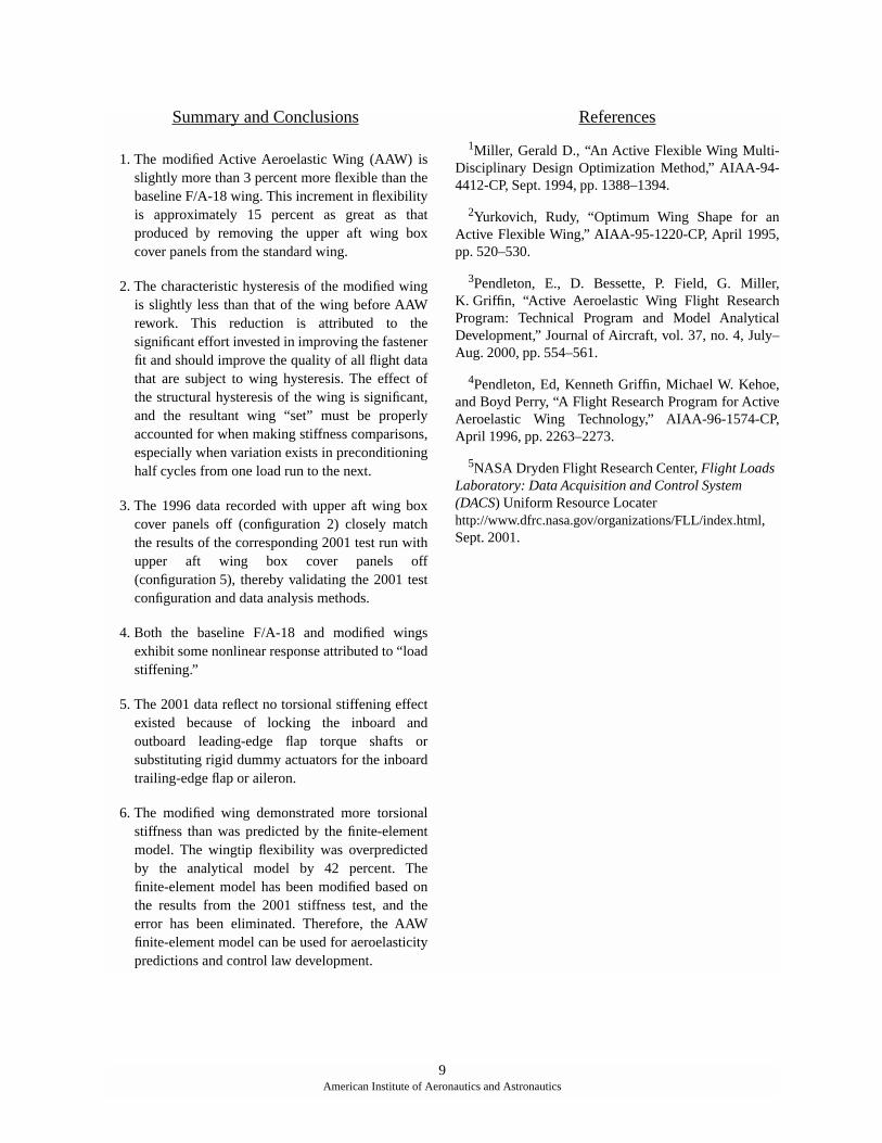
Figure 13 shows wingtip twist data from the 1996 and2001 tests plotted as a function of percent load.Structural hysteresis is noted in the height of the dataloop at zero load. Comparison of the heights of thehysteresis loops in these two plots indicates a reductionof structural hysteresis in the modified wing compared
020008
–150
5
–5–100 –50 0 50 100 150
3
4
2
1
0
–1
–2
–3
–4 Configuration 1 with 0.1227 offsetConfiguration 4 with –0.2027 offset
Win
gti
p t
wis
t, d
eg
Test limit load, percent
Figure 13. Comparison of pre- and post-AAW modtwist response.
0.05°±
0.02°±
0.07°±
7American Institute of Aeronautics and Astronautics
Table 2. Instrumentation accuracy for the twist test.
InstrumentationRange,
in. AccuracyNumber usedon left wing
Digital dial gauges 1 0.00012 in.# 19
Deflection potentiometers 1 1.0 percent** 11
3 1.0 percent** 15
6 0.5 percent** 3#Consistent error**Independent linearity error
to the wing before AAW modification. This reduction isattributed to the significant effort invested in improvingthe fastener fit for the upper and lower aft wing boxcover panels and some main wing box fasteners as well.Anecdotal data indicate that before the AAWmodifications, these wings had loose fastener fit (manywere worn beyond production tolerance); but thereworked wings have very tight fasteners. The AAWfastener rework should improve the quality of all flightdata that are subject to wing hysteresis.
This structural hysteresis must be considered whenmaking comparisons between load cases with dissimilarload profiles. The residual “set” of the wing after apositive applied torque biases response to subsequentload in the opposite manner of that produced by anegative applied torque. In this case, hysteresis offsetswere manually eliminated by shifting each data set sothat the initial twist at zero load is zero, allowing adirect comparison to be made. Comparison of the 1996data for the configurations with aft wing box coverpanels on and off indicates a flexibility increase of 24.23percent (table 3), which is considered the maximumflexibility increment possible through modification tothe panels. The slight “S” shape seen in these twistcurves is attributed to “load stiffening,” which occurswhen more of the local structure begins to share load asfastener tolerances are overcome.
Comparison of the 1996 and 2001 tests for theconfigurations with the panels on shows a flexibilityincrement of 3.28 percent. Comparison of the 1996 andthe 2001 tests for the configurations with the panels off(fig. 14) shows approximately 2-percent difference,which validates the comparability of the testingmethodologies employed. Table 3 shows a summary ofthese observations. The wing torsional flexibility valuesshown were calculated from the slope of the least
squares fit of wingtip twist versus total applied wingroot torque. Comparison of the results from the 2001test conditions of panels on and control surfaces locked(configuration 3) and panels on and control surfacesunlocked (configuration 4) reveals that no effect onwing torsional stiffness existed because of this changein control surface rigging. No significant rigid-bodydeflections were observed in any of the 1996 or 2001tests, indicating good performance of the restraintfixtures.
An in-house analysis was performed in which thedeflections from the finite-element analysis (previouslydescribed) were compared with the results from theground tests. The maximum wingtip twist from theanalytical model was (fig. 14), which resulted ina wingtip flexibility increase of 47 percent over the 1996wing twist test. The original intention was to modify theAAW stiffness FEM using the results from the 1996tests with panels on (configuration 1) and panels off(configuration 2) to bracket the expected flexibility ofthe AAW configuration. These results indicate that thestiffness of the AAW FEM was excessively reducedduring model tuning, resulting in the AAW analyticalmodel overpredicting the flexibility of the AAW wingby 42 percent. The FEM has been corrected using thelatest test results and now should prove useful foraeroelastic predictions and control law development.
Table 3. Torsional stiffness comparison.
Testconfiguration
Wingtipflexibility,deg/in-klbf
Flexibilityincrease,percent
1 0.007525
2 0.009348 24.23
3 0.007768 3.22
4 0.007772 3.28
5 0.009194 22.17
AAWFEM 0.011033
46.62
–150Torque, percent of test limit load
020009
Win
gti
p t
wis
t, d
eg
5
–100 –50 0 50 100 150
Configuration 1Configuration 2Configuration 3Configuration 4Configuration 5FEM predictions
4
3
2
1
0
–1
–2
–3
–4
–5
FEM
34
52
1
Figure 14. Summary of wing tip twist as a function ofthe percent test limit load.
4.47°±
8American Institute of Aeronautics and Astronautics
Summary and Conclusions
1. The modified Active Aeroelastic Wing (AAW) isslightly more than 3 percent more flexible than thebaseline F/A-18 wing. This increment in flexibilityis approximately 15 percent as great as thatproduced by removing the upper aft wing boxcover panels from the standard wing.
2. The characteristic hysteresis of the modified wingis slightly less than that of the wing before AAWrework. This reduction is attributed to thesignificant effort invested in improving the fastenerfit and should improve the quality of all flight datathat are subject to wing hysteresis. The effect ofthe structural hysteresis of the wing is significant,and the resultant wing “set” must be properlyaccounted for when making stiffness comparisons,especially when variation exists in preconditioninghalf cycles from one load run to the next.
3. The 1996 data recorded with upper aft wing boxcover panels off (configuration 2) closely matchthe results of the corresponding 2001 test run withupper aft wing box cover panels off(configuration 5), thereby validating the 2001 testconfiguration and data analysis methods.
4. Both the baseline F/A-18 and modified wingsexhibit some nonlinear response attributed to “loadstiffening.”
5. The 2001 data reflect no torsional stiffening effectexisted because of locking the inboard andoutboard leading-edge flap torque shafts orsubstituting rigid dummy actuators for the inboardtrailing-edge flap or aileron.
6. The modified wing demonstrated more torsionalstiffness than was predicted by the finite-elementmodel. The wingtip flexibility was overpredictedby the analytical model by 42 percent. Thefinite-element model has been modified based onthe results from the 2001 stiffness test, and theerror has been eliminated. Therefore, the AAWfinite-element model can be used for aeroelasticitypredictions and control law development.
References
1Miller, Gerald D., “An Active Flexible Wing Multi-Disciplinary Design Optimization Method,” AIAA-94-4412-CP, Sept. 1994, pp. 1388–1394.
2Yurkovich, Rudy, “Optimum Wing Shape for anActive Flexible Wing,” AIAA-95-1220-CP, April 1995,pp. 520–530.
3Pendleton, E., D. Bessette, P. Field, G. Miller,K. Griffin, “Active Aeroelastic Wing Flight ResearchProgram: Technical Program and Model AnalyticalDevelopment,” Journal of Aircraft, vol. 37, no. 4, July–Aug. 2000, pp. 554–561.
4Pendleton, Ed, Kenneth Griffin, Michael W. Kehoe,and Boyd Perry, “A Flight Research Program for ActiveAeroelastic Wing Technology,” AIAA-96-1574-CP,April 1996, pp. 2263–2273.
5NASA Dryden Flight Research Center, Flight Loads Laboratory: Data Acquisition and Control System (DACS) Uniform Resource Locater http://www.dfrc.nasa.gov/organizations/FLL/index.html, Sept. 2001.
9American Institute of Aeronautics and Astronautics
REPORT DOCUMENTATION PAGE
Form ApprovedOMB No. 0704-0188
Public reporting burden for this collection of information is estimated to average 1 hour per response, including the time for reviewing instructions, searching existing data sources, gathering andmaintaining the data needed, and completing and reviewing the collection of information. Send comments regarding this burden estimate or any other aspect of this collection of information,including suggestions for reducing this burden, to Washington Headquarters Services, Directorate for Information Operations and Reports, 1215 Jefferson Davis Highway, Suite 1204, Arlington,VA 22202-4302, and to the Office of Management and Budget, Paperwork Reduction Project (0704-0188), Washington, DC 20503.
1. AGENCY USE ONLY (Leave blank) 2. REPORT DATE 3. REPORT TYPE AND DATES COVERED
4. TITLE AND SUBTITLE 5. FUNDING NUMBERS
6. AUTHOR(S)
8. PERFORMING ORGANIZATION REPORT NUMBER
7. PERFORMING ORGANIZATION NAME(S) AND ADDRESS(ES)
9. SPONSORING/MONITORING AGENCY NAME(S) AND ADDRESS(ES) 10. SPONSORING/MONITORING AGENCY REPORT NUMBER
11. SUPPLEMENTARY NOTES
12a. DISTRIBUTION/AVAILABILITY STATEMENT 12b. DISTRIBUTION CODE
13. ABSTRACT (Maximum 200 words)
14. SUBJECT TERMS 15. NUMBER OF PAGES
16. PRICE CODE
17. SECURITY CLASSIFICATION OF REPORT
18. SECURITY CLASSIFICATION OF THIS PAGE
19. SECURITY CLASSIFICATION OF ABSTRACT
20. LIMITATION OF ABSTRACT
NSN 7540-01-280-5500 Standard Form 298 (Rev. 2-89)
Prescribed by ANSI Std. Z39-18298-102
Wing Torsional Stiffness Tests of the Active Aeroelastic Wing F/A-18Airplane
WU 706-35-00-E8-14-00-AAW
William A. Lokos, Candida D. Olney, Natalie D. Crawford, Rick Stauf,and Eric Y. Reichenbach
NASA Dryden Flight Research CenterP.O. Box 273Edwards, California 93523-0273
H-2481
National Aeronautics and Space AdministrationWashington, DC 20546-0001 NASA/TM-2002-210723
The left wing of the Active Aeroelastic Wing (AAW) F/A-18 airplane has been ground–load-tested to quantify itstorsional stiffness. The test has been performed at the NASA Dryden Flight Research Center in November 1996, andagain in April 2001 after a wing skin modification was performed. The primary objectives of these tests were tocharacterize the wing behavior before the first flight, and provide a before-and-after measurement of the torsionalstiffness. Two streamwise load couples have been applied. The wing skin modification is shown to have more torsionalflexibility than the original configuration has. Additionally, structural hysteresis is shown to be reduced by the skinmodification. Data comparisons show good repeatability between the tests.
Ground load testing, Wing deflection measurement, Wing elastic twist, Wingflexibility, Wing torsional stiffness
12
Unclassified Unclassified Unclassified Unlimited
May 2002 Technical Memorandum
Presented at the 43rd AIAA/ASME/ASCE/AHS Structures, Structural Dynamics and Materials Conference,Denver, Colorado, April 2002. AIAA-2002-1333.
Unclassified—UnlimitedSubject Category 05
This report is available at http://www.dfrc.nasa.gov/DTRS/