Embed Size (px)
Citation preview
WinRiver II Quick Start Guide
P/N 957-6230-00 (December 2011)
© 2011 Teledyne RD Instruments, Inc. All rights reserved.


Table of Contents ................................................................................................................................................... 1 WinRiver II Quick Start Guide
Introduction ................................................................................................................................................................................ 1 How to Contact Teledyne RD Instruments ................................................................................................................................. 1 Overview .................................................................................................................................................................................... 2 Hardware Overview .................................................................................................................................................................... 2
ADCP Requirements ............................................................................................................................................................. 2 ADCP Mounting Requirements ............................................................................................................................................ 2
Software Overview ..................................................................................................................................................................... 3 Installing the Software................................................................................................................................................................ 4
Setting up Communications ...................................................................................................................................................... 5 BBTalk Communications Setup ................................................................................................................................................... 5 Changing the Baud Rate in the ADCPs ........................................................................................................................................ 6 WinRiver II Communications Setup ............................................................................................................................................ 8
Rio Grande and WorkHorse ADCP Communications Setup .................................................................................................. 8 RiverRay and StreamPro Communication Setup .................................................................................................................. 9 Adding GPS, Depth Sounders, or External Heading Devices............................................................................................... 11 Advanced ADCP Communications Configuration ............................................................................................................... 12
Customizing WinRiver II ......................................................................................................................................................... 13 User Options ............................................................................................................................................................................. 13 General Preferences ................................................................................................................................................................. 14 Creating Workspaces ................................................................................................................................................................ 15
Collecting River Discharge Data .............................................................................................................................................. 16 Connect the ADCP .................................................................................................................................................................... 16 Run the Measurement Wizard ................................................................................................................................................. 16
Site Information ................................................................................................................................................................. 17 Rating Information ............................................................................................................................................................. 17 Configuration Dialog .......................................................................................................................................................... 18 Output Filename Options ................................................................................................................................................... 21 Commands Preview ........................................................................................................................................................... 22 Summary Page ................................................................................................................................................................... 22
QA/QC Items............................................................................................................................................................................. 23 Set ADCP Clock ................................................................................................................................................................... 23 Test ADCP ........................................................................................................................................................................... 23 Test Pressure Sensor .......................................................................................................................................................... 24 Compass Calibration .......................................................................................................................................................... 24 Moving Bed Test................................................................................................................................................................. 25
Mark Transect Start and End Points ......................................................................................................................................... 26 Adjust the Configuration .......................................................................................................................................................... 28 Transects .................................................................................................................................................................................. 29
Step by Step Data Collection .............................................................................................................................................. 31 Data Collections Tips .......................................................................................................................................................... 32
Viewing Data with WinRiver II ................................................................................................................................................ 33 Reprocessing Data .................................................................................................................................................................... 34
Averaging Data ................................................................................................................................................................... 34 Transect Subsection ........................................................................................................................................................... 34 HYDROML Export ............................................................................................................................................................... 35 Data Screening ................................................................................................................................................................... 35 Corrections to the Playback Configuration Node ............................................................................................................... 36 ASCII-Out ............................................................................................................................................................................ 36
Discharge Summary .................................................................................................................................................................. 37 Using the WinRiver II Q Measurement Summary ..................................................................................................................... 38 Print a Plot or Display ............................................................................................................................................................... 39 Screen Captures........................................................................................................................................................................ 39
Water Profiling Modes ........................................................................................................................................................... 40 Commonly Used ADCP Commands ......................................................................................................................................... 41 Commonly Used BBTalk Commands ....................................................................................................................................... 41 WinRiver II Shortcut Keys ....................................................................................................................................................... 42 Where to Find More Information ........................................................................................................................................... 43
List of Figures Figure 1. Overview of Data Collection....................................................................................................................... 32
List of Tables Table 1: Recommended River Water Profiling Modes .............................................................................................. 40 Table 2: Commonly Used ADCP Commands ............................................................................................................. 41 Table 3: Commonly Used BBTalk Commands ........................................................................................................... 41
Revision History November 2011
• Updated screen captures for Measurement Wizard Configuration Dialog.
• Updated fonts and styles used in manual.
WinRiver II Quick Start Guide
P/N 957-6230-00 (December 2011) page 1
WinRiver II Quick Start Guide
Introduction Thank you for purchasing the Teledyne RD Instruments (TRDI) WinRiver II software. This Quick Start Guide will lead you through the steps required for a successful river discharge measurement. Please read the entire guide, and then follow the instructions in the order they are presented. Additional in-formation can be found in the WinRiver II User’s Guide that is supplied on CD-ROM.
NOTE. To purchase a printed copy of the WinRiver II User’s Guide, contact our Customer Service department at [email protected] or call +1 (858) 842-2600 and order the WinRiver II User’s Guide P/N 957-6231-00.
NOTE. This guide covers WinRiver II version 2.08.
How to Contact Teledyne RD Instruments If you have technical issues or questions involving a specific application or deployment with your in-strument, contact our Field Service group:
Teledyne RD Instruments Teledyne RD Instruments Europe
14020 Stowe Drive Poway, California 92064
2A Les Nertieres 5 Avenue Hector Pintus 06610 La Gaude, France
Phone +1 (858) 842-2600 Phone +33(0) 492-110-930
FAX +1 (858) 842-2822 FAX +33(0) 492-110-931
Sales – [email protected] Sales – [email protected]
Field Service – [email protected] Field Service – [email protected]
Client Services Administration – [email protected] Web: http://www.rdinstruments.com
24 Hour Emergency Support +1 (858) 842-2700
WinRiver II Quick Start Guide
page 2 Teledyne RD Instruments
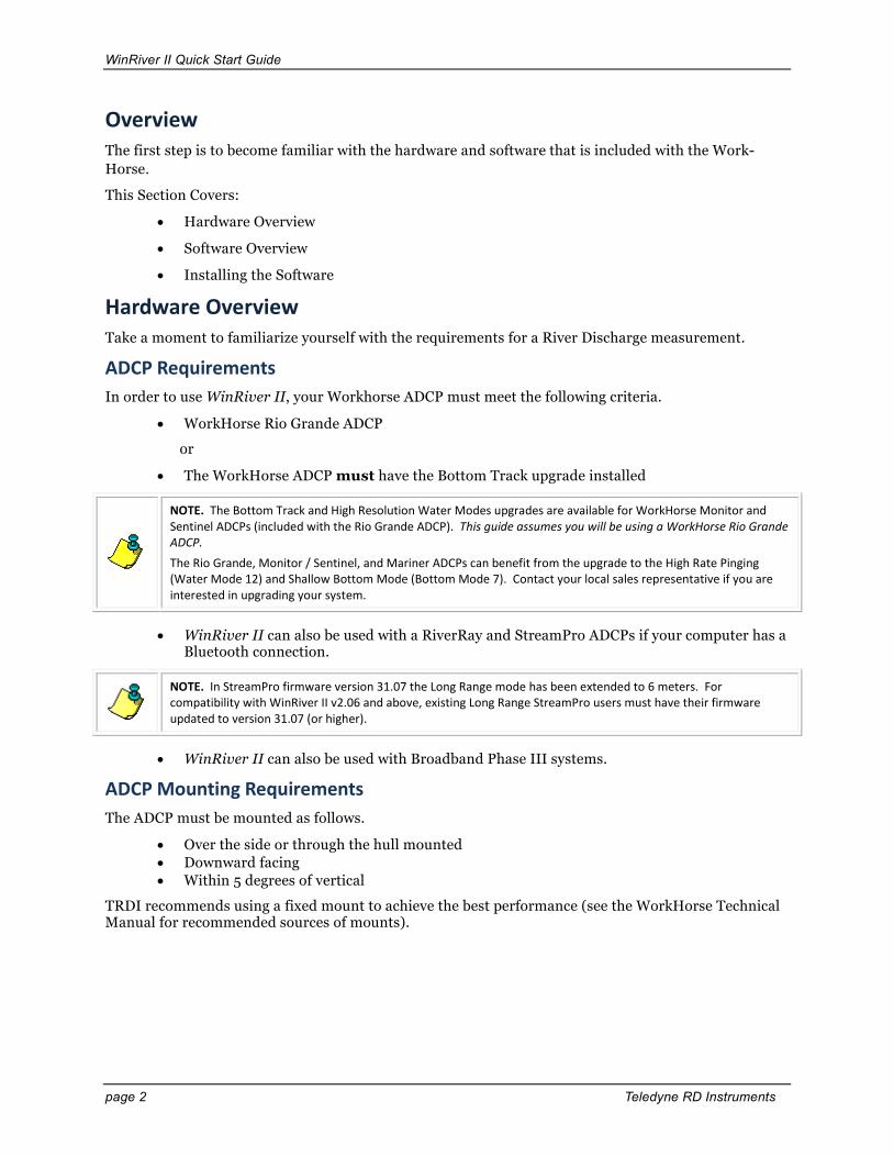
Overview The first step is to become familiar with the hardware and software that is included with the Work-Horse. This Section Covers:
• Hardware Overview
• Software Overview
• Installing the Software
Hardware Overview Take a moment to familiarize yourself with the requirements for a River Discharge measurement.
ADCP Requirements In order to use WinRiver II, your Workhorse ADCP must meet the following criteria.
• WorkHorse Rio Grande ADCP
or
• The WorkHorse ADCP must have the Bottom Track upgrade installed
NOTE. The Bottom Track and High Resolution Water Modes upgrades are available for WorkHorse Monitor and Sentinel ADCPs (included with the Rio Grande ADCP). This guide assumes you will be using a WorkHorse Rio Grande ADCP. The Rio Grande, Monitor / Sentinel, and Mariner ADCPs can benefit from the upgrade to the High Rate Pinging (Water Mode 12) and Shallow Bottom Mode (Bottom Mode 7). Contact your local sales representative if you are interested in upgrading your system.
• WinRiver II can also be used with a RiverRay and StreamPro ADCPs if your computer has a Bluetooth connection.
NOTE. In StreamPro firmware version 31.07 the Long Range mode has been extended to 6 meters. For compatibility with WinRiver II v2.06 and above, existing Long Range StreamPro users must have their firmware updated to version 31.07 (or higher).
• WinRiver II can also be used with Broadband Phase III systems.
ADCP Mounting Requirements The ADCP must be mounted as follows.
• Over the side or through the hull mounted • Downward facing • Within 5 degrees of vertical
TRDI recommends using a fixed mount to achieve the best performance (see the WorkHorse Technical Manual for recommended sources of mounts).

WinRiver II Quick Start Guide
P/N 957-6230-00 (December 2011) page 3
Software Overview You will use two software programs to test and collect data with the WorkHorse ADCP.
BBTalk Main Screen BBTalk is a dumb terminal emulator pro-gram. It is primarily used to run the ADCP pre-deployment tests and to confirm com-munications. This guide does not go into detail about the operation of BBTalk. For more information see the RDI Tools User’s Guide.
WinRiver II Main Screen WinRiver II is the software used to set con-figurations, collect data, and playback pre-vious transects.

WinRiver II Quick Start Guide
page 4 Teledyne RD Instruments
Installing the Software You will be installing two software packages: RDI Tools (contains BBTalk) and WinRiver II. These will be required for testing and measurements.
The software requires the following:
• Windows Vista®, Windows XP Pro® or Windows 2000®
• Pentium III 600 MHz class PC (higher recommended)
• 64 megabytes of RAM (128 MB RAM recommended)
• 50 MB Free Disk Space plus space for data files (A large, fast hard disk is recommended)
• One Serial Port (two or more High Speed UART Serial Ports recommended)
• Minimum display resolution of 1024 x 768
• CD-ROM Drive
• Mouse or other pointing device
Software Installation a. Insert the compact disc into your CD-
ROM drive and then follow the browser instructions on your screen. If the browser does not appear, complete Steps "b" through "d."
b. On the Windows task bar, click the Start button, and then click Run.
c. Type <drive>:launch. For example, if your CD-ROM drive is drive D, type d:launch.
d. Follow the browser instructions on your screen
WinRiver II Quick Start Guide
P/N 957-6230-00 (December 2011) page 5
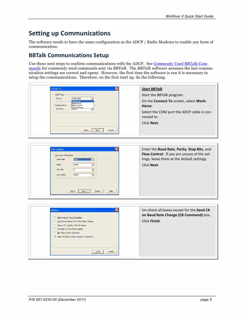
Setting up Communications The software needs to have the same configuration as the ADCP / Radio Modems to enable any form of communication.
BBTalk Communications Setup Use these next steps to confirm communications with the ADCP. See Commonly Used BBTalk Com-mands for commonly used commands sent via BBTalk. The BBTalk software assumes the last commu-nication settings are correct and opens. However, the first time the software is run it is necessary to setup the communications. Therefore, on the first start up, do the following.
Start BBTalk Start the BBTalk program. On the Connect To screen, select Work-Horse. Select the COM port the ADCP cable is con-nected to. Click Next.
Enter the Baud Rate, Parity, Stop Bits, and Flow Control. If you are unsure of the set-tings, leave them at the default settings. Click Next.
Un-check all boxes except for the Send CK on Baud Rate Change (CB Command) box. Click Finish.

WinRiver II Quick Start Guide
page 6 Teledyne RD Instruments
Wakeup On the File menu, click Break (you can also press the End key to send a break or and press the B button on the Toolbar). To send a break when using a Radio Mo-dem, press === (3 equals). You should see the wakeup message appear on the log file window.
If the wakeup message is not readable, do the following. On the File menu, click Properties. Click the Auto Detect ADCP button. Click OK when the ADCP is detected. Try to wakeup the ADCP again.
What if the ADCP does not respond?
If your ADCP does not respond, check the serial port, cables, AC power, 12 VDC battery power (Rio Grande only), and battery connection (Sentinel only). If necessary, refer to the Troubleshooting section in the WorkHorse Technical Manual.
Changing the Baud Rate in the ADCPs The Rio Grande and WorkHorse ADCPs can be set to communicate at baud rates from 300 to 115200. The factory default baud rate is always 9600 baud. The baud rate is controlled via the CB-command. The following procedure explains how to set the baud rate and save it in the ADCP. This procedure as-sumes that you will be using the program BBTalk that is supplied by Teledyne RD Instruments.
NOTE. This applies to WorkHorse ADCPs only. StreamPro and RiverRay ADCPs use 115200 baud rate (see StreamPro Communication Setup).

WinRiver II Quick Start Guide
P/N 957-6230-00 (December 2011) page 7
> [BREAK Wakeup A] WorkHorse Rio Grande Broadband ADCP Version 10.15 RD Instruments (c) 1996-2005 All Rights Reserved. > >cr1 [Parameters set to FACTORY defaults]
Connect the ADCP to the computer and apply power. Start the BBTalk program and establish communications with the ADCP. Wakeup the ADCP by sending a break signal with the End key. At the ">" prompt in the communication window, type CR1 then press the Enter key. This will set the ADCP to the factory default settings.
BAUD RATE CB-command
300 CB011
1200 CB111
2400 CB211
4800 CB311
9600 CB411 (Default)
19200 CB511
38400 CB611
57600 CB711
115200 CB811
Send the CB-command that selects the baud rate you wish. The table on the left shows the CB-command settings for differ-ent baud rates with no parity and 1 stop bit. For example, to change the baud rate to 115200, at the ">" prompt in the communi-cation window, type cb811 then press the Enter key.
The CB? command will identify the communication setting.
>cb? CB = 411 ----------------- Serial Port Control (Baud [4=9600]; Par; Stop) >cb811 >CK [Parameters saved as USER defaults] >cb? CB = 811 ----------------- Serial Port Control (Baud [8=115200]; Par; Stop) >
BBTalk will send the command CK to save the new baud rate setting. Exit BBTalk. The ADCP is now set for the new baud rate. The baud rate will stay at this setting until you change it back with the CB-command.
Exit BBTalk so the communication port is available for use with WinRiver II.

WinRiver II Quick Start Guide
page 8 Teledyne RD Instruments
WinRiver II Communications Setup When WinRiver II is first started, you must set up the communications with the ADCP, GPS (if used), external heading (if used), and Depth Sounder (if used). Once setup, WinRiver II will remember the settings and use them each time the program is started.
Rio Grande and WorkHorse ADCP Communications Setup
Connect and power up the ADCP as shown in the appropriate ADCP User's Guide. Start WinRiver II. On the Configure menu, select Peripherals. Click the + box next to Read Serial Raw ADCP Data to expand the list and then se-lect Port: ADCP Serial Port. Press the Configure button.
Select the communication port, Baudrate, Databits, Parity, and Stopbits. Click OK to return to the Peripheral Config-uration Dialog.
Click the Test Port button to connect to the ADCP and confirm the communication set-ting. You should see the wakeup message appear on the log file window. Click the Close button to return to the Pe-ripheral Configuration Dialog.
If no wakeup message appears, see Advanced ADCP Communications Configu-ration and use the Send Break button.

WinRiver II Quick Start Guide
P/N 957-6230-00 (December 2011) page 9
RiverRay and StreamPro Communication Setup WinRiver II can also be used with a RiverRay and StreamPro ADCP if your computer has a Bluetooth connection.
Turn on the power to the StreamPro ADCP. Configure your Bluetooth device. It should locate the RiverRay or StreamPro ADCP (RDI RRay 00xxx or RDI SPro 00xxx where xxx is the serial number).
This screen may look different based on what Bluetooth device you are using.
Some Bluetooth configurations require a pin code for StreamPro and RiverRay ADCPs.
The pin code is 0.
Double-click on the RDI SPro or RDI RRay icon and make sure that that it shows Con-nected. Make note of the Com Port number it is using. On this example, the StreamPro is connected to Com Port 18.

WinRiver II Quick Start Guide
page 10 Teledyne RD Instruments
Start WinRiver II. On the Configure menu, select Peripherals. Click the + box next to Read Serial Raw ADCP Data to expand the list and then se-lect Port: ADCP Serial Port. Press the Configure button.
Select the communication port identified when setting up the Bluetooth device (in this example, Com Port 18). Set the Baudrate to 115200. Leave the Databits set to 8, Parity to None, and Stopbits set to 1. Click OK to return to the Peripheral Config-uration Dialog.
Click the Test Port button to connect to the StreamPro ADCP and confirm the communi-cation setting. You should see the wakeup message appear on the log file window. Click the Close button to return to the Pe-ripheral Configuration Dialog. Click Close once more to exit the communication set-ting.
If no wakeup message appears, use BBTalk to troubleshoot the communica-tions.
NOTE. The blue LED on the StreamPro ADCP lights when communicating with WinRiver II. It may go off when no serial communications are in process. This is normal and does not signify any problem.
WinRiver II Quick Start Guide
P/N 957-6230-00 (December 2011) page 11
Adding GPS, Depth Sounders, or External Heading Devices
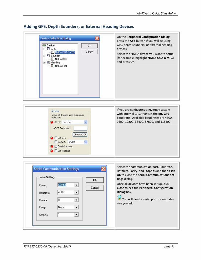
On the Peripheral Configuration Dialog, press the Add button if you will be using GPS, depth sounders, or external heading devices. Select the NMEA device you want to setup (for example, highlight NMEA GGA & VTG) and press OK.
If you are configuring a RiverRay system with internal GPS, than set the Int. GPS baud rate. Available baud rates are 4800, 9600, 19200, 38400, 57600, and 115200.
Select the communication port, Baudrate, Databits, Parity, and Stopbits and then click OK to close the Serial Communications Set-tings dialog. Once all devices have been set up, click Close to exit the Peripheral Configuration Dialog box.
You will need a serial port for each de-vice you add.

WinRiver II Quick Start Guide
page 12 Teledyne RD Instruments
Advanced ADCP Communications Configuration Use the following steps to communicate with the ADCP or verify command settings.
On the Configure menu, select Peripherals. Click the + box next to Read Serial Raw ADCP Data to expand the list and then se-lect Instrument: ADCP Instrument. Press the Configure button.
Right-click on Instrument: ADCP In-strument and select Auto Detect to auto-matically detect the serial port settings.
Use the Advanced ADCP Configuration Dia-log screen to send or verify command set-ting as needed. If the command you want to send the ADCP is not on the list, type it next to the “>” prompt in the Terminal Window and press return.
Use the Send Break button to wake up the ADCP.
CAUTION. Do not use this screen to deploy or configure the ADCP. The commands will be overwritten when Acquire, Start Pinging (F4) is pressed. Only the commands generated through the wizard and sent via Acquire, Start Pinging (F4) can be used to deploy the ADCP.
NOTE. WorkHorse Monitor/Sentinel ADCPs will go to sleep if a command is not sent within five minutes; Use the Send Break button to wake the ADCP before you start pinging. WorkHorse Rio Grande ADCPs do not sleep. For more information, see the CL command in the WorkHorse Commands and Output Data Format guide.

WinRiver II Quick Start Guide
P/N 957-6230-00 (December 2011) page 13
Use the One Step Setup to check the de-ployment commands sent to the ADCP after the Measurement Wizard has been com-pleted (see Run the Measurement Wizard). Run the Measurement Wizard. Click One Step Setup. Click the Send but-ton. If any command generates an error mes-sage, stop and correct the problem before deploying.
This is a good way to check if any com-mand generates an error message.
CAUTION. Do not use this screen to deploy or configure the ADCP. The commands will be overwritten when Acquire, Start Pinging (F4) is pressed. Only the commands generated through the wizard and sent via Acquire, Start Pinging (F4) can be used to deploy the ADCP.
NOTE. The One Step Setup is a good way to check if any command generates an error message (for example, if the commands depend on the High Resolution Water Profiling upgrade but you are not sure the ADCP has this feature). If a command generates an error, a message box will appear. The One Step Setup does not check the commands for “reasonableness”. If the wizard has not been run, the Fixed and Wizard command boxes will be blank. Commands can be entered in the User box or at the “>” prompt.
Customizing WinRiver II WinRiver II can be customized to look and act as you prefer. Once setup, WinRiver II will remember the settings and use them each time the program is started.
User Options
On the File menu, click Properties. The Properties dialog sets how WinRiver II be-haves upon entering the Acquire mode.

WinRiver II Quick Start Guide
page 14 Teledyne RD Instruments
Click on General Configuration to change how workspace files are loaded or saved. Check the Reset Wizard to Defaults box to have the measurement wizard use the de-fault settings based on a WorkHorse Rio Grande 600 kHz ADCP. Check the While Loading a Raw Data File box to begin displaying data while the file is loading. For smaller data files, this may not be noticeable.
General Preferences
On the Configure menu, click Reference. Select the desired reference: None, Bottom Track, GPS (GGA), or GPS (VTG).
If the wrong reference is selected dur-ing Playback, data may not display. For example, if you select GPS (GGA) as the reference during Playback and this was not collected when the data file was created, no data will display.
To change the units for all displays, on the Configure menu, select Units. You can change units to All English, All SI or use the Advanced menu and select each unit for Velocity, Range/Depth, and Tem-perature.
When using a StreamPro ADCP on small streams/channels, change the Velocity units to mm/s or cm/sec. This will change the discharge to mm3/s or cm3/s.

WinRiver II Quick Start Guide
P/N 957-6230-00 (December 2011) page 15
On the Configure menu, click Averaging Data… Enter a number greater than one to average the data.
Averaging data may provide smoother plots. This does not alter the raw data in any way.
Creating Workspaces A Workspace is a collection of windows arranged and sized as you prefer, and then saved for future use as needed. It is possible to define as many different workspaces as you would like.
To create a Workspace file, use the View menu to open all the windows you want to see during data collection or playback. Arrange the views you are interested in.
How workspaces are loaded and saved when starting/closing WinRiver II depends on the User Options (see User Options).
When you have the displays set up the way you prefer, on the File menu, click Save Workspace File As. To use a workspace, on the File menu, click Load Workspace.
WinRiver II Quick Start Guide
page 16 Teledyne RD Instruments
Collecting River Discharge Data This section has simple instructions for a typical discharge measurement using the ADCP only (no GPS, External Heading, or Depth Sounder).
Connect the ADCP
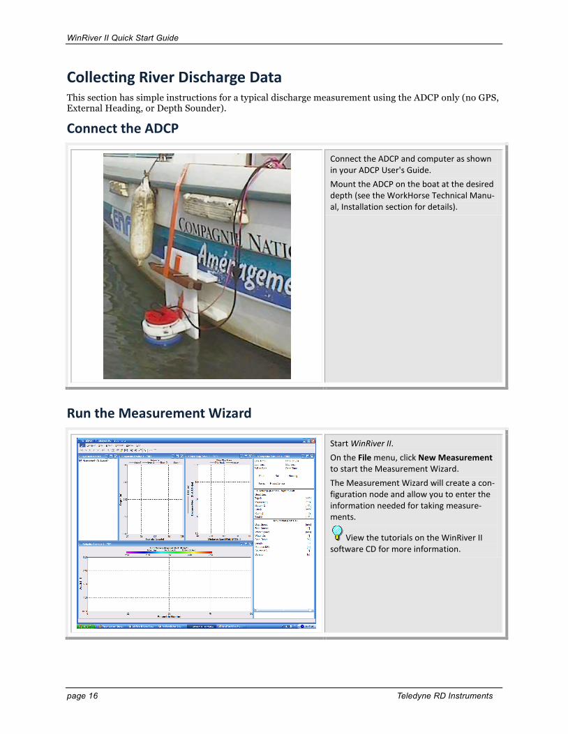
Connect the ADCP and computer as shown in your ADCP User's Guide. Mount the ADCP on the boat at the desired depth (see the WorkHorse Technical Manu-al, Installation section for details).
Run the Measurement Wizard
Start WinRiver II. On the File menu, click New Measurement to start the Measurement Wizard. The Measurement Wizard will create a con-figuration node and allow you to enter the information needed for taking measure-ments.
View the tutorials on the WinRiver II software CD for more information.

WinRiver II Quick Start Guide
P/N 957-6230-00 (December 2011) page 17
Site Information
Enter the Site Information. Enter a Station Name and Measurement Number (alphanumeric). This can be added to the file name (see Output Filename Op-tions). Click Next.
This information will be included in the Q Measurement Summary (see Using the WinRiver II Q Measurement Summary).
You can add/edit this information once the measurement wizard is completed by right-clicking on Site Information in the Measurement Control window and select-ing Site Wizard.
Rating Information
Enter the Rating Information. Click Next.
This information will be included in the Q Measurement Summary (see Using the WinRiver II Q Measurement Summary).
You can add/edit this information once the measurement wizard is completed by right-clicking on Site Information in the Measurement Control window and select-ing Site Wizard.

WinRiver II Quick Start Guide
page 18 Teledyne RD Instruments
If you see this screen and the ADCP is NOT attached to a serial port, click Cancel to continue the Measurement Wizard. If the ADCP is attached to a serial port, click Yes to configure the port.
The ADCP does not need to be con-nected to use the wizard.
If you see the following message box, this means WinRiver II is not sure what type ADCP you are using. Click OK to continue.
Configuration Dialog
Enter your choices for how the configura-tion will be setup.
See the following tables for details.

WinRiver II Quick Start Guide
P/N 957-6230-00 (December 2011) page 19
A green circle means that the communication port has been configured and tested. Red circles mean the device has not been configured.
Devices Enter your choices for the Devices section. See WinRiver II Communications Setup for instructions on how to setup communica-tions between WinRiver II and the ADCP. If you are using a Rio Grande ADCP, WinRiv-er II will automatically detect and enter the ADCP Serial Number, otherwise enter the serial number. Use the Check ADCP button to verify the ADCP communications set-tings. Selecting the GPS, Depth Sounder, or Ext. Heading boxes will prompt you to set up the communication settings for the device. If you are configuring a RiverRay system with internal GPS, than set the Int. GPS baud rate. Available baud rates are 4800, 9600, 19200, 38400, 57600, and 115200.
The transducer depth should be checked periodically dur-ing data collection.
Offsets Use the Transducer Depth field to set the depth from the water surface to the center of the ADCP transducer faces. Enter the Magnetic Variation for the site. See the WinRiver II User’s Guide for details on how to determine the Magnetic Varia-tion Correction.

WinRiver II Quick Start Guide
page 20 Teledyne RD Instruments
It is recommended that the boat speed be less than or equal to the water speed.
Leave the Bottom and Water Mode set to Auto. WinRiver II will select a best suited mode based on the water depth, speed, and streambed material.
ADCP Wizard Configuration Enter your choices for the ADCP Configura-tion section. Based on the entered infor-mation, the wizard will generate the ADCP commands. The Max Water Depth, Max Water Speed, and Max Boat Speed should be defined as close as possible to the actual conditions. Set the Secondary Depth to the mini-mum depth that will be measured in the river. Usually this will be a smaller value than the Max Depth or left at zero. Streambed material should then be select-ed: this does not affect the configuration but it assists in producing relevant warn-ings. Bottom Mode and Water Mode - See Table 1 for setup table.
For more information on the Discharge settings, see the WinRiver II User’s Guide, Discharge Page.
Discharge Enter your choices for the Discharge sec-tion. Select method for calculating the discharge of the unmeasured areas (Power, Constant or 3pt Slope). You can also select a coeffi-cient; however, the default Power method is standard. Select the style of the Left and Right banks (Triangular, Square or User). Banks should be selected by facing downstream. Shore Pings dictates the amount of ensem-bles that will be used to calculate the edge discharge. Click Next.
You should always use a minimum of 10 shore pings.

WinRiver II Quick Start Guide
P/N 957-6230-00 (December 2011) page 21
Output Filename Options
If a Station Name was entered on the first page of the wiz-ard, it will be used in the Filename Prefix box.
WinRiver II uses the Filename Prefix to cre-ate the data file names made during data collection. Use the Output Directory field to select where the data file will be stored. Check the Measurement Number box to add it to the file name (see Site Infor-mation). Check the Sequence Number box and enter a Max File Size if you want to limit the size of the data file. Once the file size has been reached, the sequence number will incre-ment. To add the Date/Time to the filename, check the Short (YY-MM-DD) or Long (YY-MM-DD hhmmss) button. Select what type delimiter to use in the filename by selecting No Delimiter, Under-score, or Custom. Click Next.

WinRiver II Quick Start Guide
page 22 Teledyne RD Instruments
Commands Preview
See Table 2 for a short list of ADCP commands commonly sent via WinRiver II.
The Commands Preview is where adjust-ments can be made to the commands pro-duced by the measurement wizard. There are three columns - the first is the Fixed commands that are sent by default by WinRiver II to the ADCP. The second column is commands that are produced by the Wizard; these commands will overwrite the corresponding original fixed commands. The final column is for User commands; these can be added to by the user, and just as before, these commands will overwrite the previous column. Do not enter any commands in the User section unless you are fully aware of what the command does. Click Next.
Summary Page
Review the Summary Page. When done, click Finish.
A green check mark next to WM12 and BM7 means that the ADCP is capable of using these modes, not that the mode is selected. View the ADCP Wizard Configuration sec-tion to see what water and bottom mode is selected.

WinRiver II Quick Start Guide
P/N 957-6230-00 (December 2011) page 23
QA/QC Items Before taking measurements, check the following items.
Set ADCP Clock
On the Acquire menu, click Set ADCP Clock. Click the Set Clock button to set the ADCP’s time to the GPS time (if available) or the PC’s time. If necessary, set the PC's clock first.
The first time a transect is started, the Set ADCP Clock dialog will open.
StreamPro ADCPs users will notice that the blue LED will flash until the Close but-ton is clicked. This is normal. The TS com-mand is send once per second until the close button is clicked.
Test ADCP
On the Acquire menu, click Execute ADCP Test to verify the ADCP is functioning properly. Click the Stop PC2 button to end the PC2 test. Click Close to exit the RGTest dialog.
The tests should be run while the ADCP is in non moving water. Running the test in air will not harm the ADCP, but some tests may fail in air.
Do not use the RGTest on a StreamPro ADCP. Use BBTalk to test a StreamPro ADCP.

WinRiver II Quick Start Guide
page 24 Teledyne RD Instruments
Test Pressure Sensor
On the Acquire menu, click Execute Pres-sure Sensor Test to verify the ADCP’s pres-sure sensor is functioning properly. Click the Read Pressure Sensor button to get samples. Click the Zero Pressure Sensor button to zero out the sensor.
If your ADCP does not have a pressure sensor, you will see an error message.
Do not use the Pressure Sensor Test on a StreamPro ADCP. StreamPro systems do not have a pressure sensor.
Compass Calibration
For more information on the Compass Calibration, see the WinRiver II User’s Guide, Integrating Depth Sounder, Exter-nal Heading, and GPS Data.
On the Acquire menu, click Execute Com-pass Calibration. Click on the Calibrate button to begin the compass calibration.
If you will be using GPS rather than Bot-tom Track as the reference, then the com-pass must be calibrated and the Magnetic Variation for the site entered on the Con-figuration Dialog page (see Configuration Dialog). See the WinRiver II User’s Guide for details on compass calibration and magnetic varia-tion corrections procedures.

WinRiver II Quick Start Guide
P/N 957-6230-00 (December 2011) page 25
Moving Bed Test During high flow season or where the river sediment load is high, acoustic absorption and scattering interfere with the bottom tracking of ADCPs. The Moving Bed test should be performed at every site gauged, and made every time the site is visited as conditions do change. The test can also act as a pre-survey; the data retrieved can be used in the Measurement Wizard to set the depth and velocity.
The Moving Bed test is to prove that the bed of the section is not in motion. If you obtain biased bottom track data at your river site, moving to a new section may help, but flood conditions may require the use of GPS.
The Loop Test method was developed by USGS and is not directly supported by TRDI. For more information, refer to the USGS document concerning the loop method at the following link: http://pubs.usgs.gov/sir/2006/5079/
Using the Measurement Wizard, set an estimated depth and velocity, and use Wa-ter Mode 1 and Bottom Mode 5. These modes can be varied to suit the section bet-ter. On the Acquire menu click Start Pinging or use the shortcut key F4. Move the ADCP to the middle of the sec-tion, or the point at which the highest ve-locities can be seen. On the Acquire menu click Moving Bed Test. Select Stationary and click the Start button. Hold the unit in position for ten minutes and try to minimize any movement.
Ship track indicating NO Moving Bed.
Graph scales indicate minimum movement.
Keep a close eye on the Ship Track Plot. Any movement indicated on here above actual movement would indicate a Moving Bed. On the Acquire menu click Stop Moving Bed Test. Review the data; if this indicates bed movement, move to a more suitable sec-tion. Save the measurement project. Use data to set a better configuration for transects.
WinRiver II Quick Start Guide
page 26 Teledyne RD Instruments
Mark Transect Start and End Points You must determine the start and end positions prior to beginning measurements as WinRiver II uses this data to extrapolate for the edges. Typically, 10 shore ensembles are taken as close to the riverbank as can be measured and still read valid data. Ensembles that contain a minimum of two good depth cells are considered valid data. Once these points have been determined, they should be marked and used for the remaining transects.
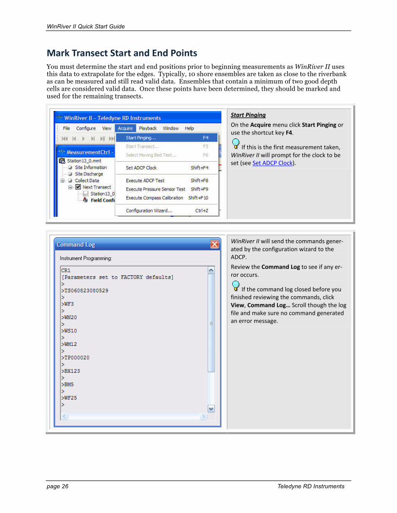
Start Pinging On the Acquire menu click Start Pinging or use the shortcut key F4.
If this is the first measurement taken, WinRiver II will prompt for the clock to be set (see Set ADCP Clock).
WinRiver II will send the commands gener-ated by the configuration wizard to the ADCP. Review the Command Log to see if any er-ror occurs.
If the command log closed before you finished reviewing the commands, click View, Command Log… Scroll though the log file and make sure no command generated an error message.

WinRiver II Quick Start Guide
P/N 957-6230-00 (December 2011) page 27
Click View, Tabular, Velocity to open a Ve-locity Tabular 1 display. Move out from the shore until the water is deep enough to consistently show good values for two bins (or more depending on river conditions and how close you can get to the shore). Values of 0.0 are acceptable, but “bad” values are invalid. Mark this position (with a float). This is the starting/stopping position for this shore. You will later start/stop data file recording at this location depending on the direction of your transect.
Move out from the shore traveling slowly with the bow of the boat pointed upstream.
Use the Velocity Magnitude Contour display to see how the water depth changes as you make your transect. Note regions where the bottom depth changes quickly.
Switch back to the Velocity Tabular 1 dis-play. When you approach the other shore, mark the closest distance to shore where two depth cells show discharge values. This will be the start/stopping point for this shore.
Start/Stop distances from the center of the transducer to the shore should be measured as accurately as possible - at least to the nearest deci-meter.

WinRiver II Quick Start Guide
page 28 Teledyne RD Instruments
Adjust the Configuration After the Moving Bed Test and the Start/Stop points for the transects have been determined, you may want to make adjustments to the configuration. Perhaps you noticed that the river is deeper than origi-nally entered or you want to use a different Water Mode or Bottom Mode than you used for the moving bed test.
NOTE. You can adjust the Field Configuration as long as data has not been collected with the node (it will have Next Transect XXX, where XXX is the transect number and the transect check box is grey).
Right-click on Field Configuration and select Configuration Wizard.
The ADCP communication setting will be checked again and then will open at the Configuration Dialog page (see Configura-tion Dialog). Make changes as needed and click Next. In this example, the Maximum Water Depth was increased to 6.25 meters. Win-River II is suggesting that the Water Mode may need to be set to Mode 1 or Mode 12 for best results. If necessary, run another test transect and make further adjustments. Continue through the wizard by clicking Next at each page and then select Finish at the Summary page.
WinRiver II Quick Start Guide
P/N 957-6230-00 (December 2011) page 29
Transects
Best practices encourage a minimum of four high quality transects be collected that agree with each other to within 5% of the mean of all the samples. The following sequence must be repeat-ed for every transect taken over the water body.
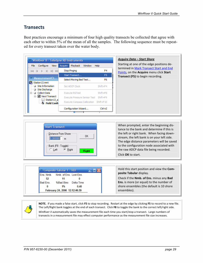
Acquire Data – Start Shore Starting at one of the edge positions de-termined in Mark Transect Start and End Points, on the Acquire menu click Start Transect (F5) to begin recording.
When prompted, enter the beginning dis-tance to the bank and determine if this is the left or right bank. When facing down-stream, the left bank is on your left side. The edge distance parameters will be saved to the configuration node associated with the raw ADCP data file being recorded. Click OK to start.
Hold this start position and view the Com-posite Tabular display. Check if the Nmb. of Ens. minus any Bad Ens. is more (or equal) to the number of shore ensembles (the default is 10 shore ensembles).
NOTE. If you made a false start, click F5 to stop recording. Restart at the edge by clicking F5 to record to a new file. The Left/Right bank toggles at the end of each transect. Click F8 to toggle the bank to the correct left/right side. WinRiver II automatically saves the measurement file each time you start/stop a transect. Large numbers of transects in a measurement file may effect computer performance as the measurement file size increases.

WinRiver II Quick Start Guide
page 30 Teledyne RD Instruments
Move across the river as smoothly as possi-ble. For the best measurement results, the boat’s speed over the bottom should be no greater than the water speed of the river. Pointing the bow of the boat upstream and slowly crabbing across the river will help to maintain a transect path that is perpendicu-lar to the flow.
Move away from the starting point smoothly. If you can not keep the speed as slow and smooth as needed due to a large motor, use a trawling motor instead. Smoothness is most important; On large rivers speed may need to be higher than desired for many reasons.
Continue across the river until you reach the stop position determined in Mark Tran-sect Start and End Points. Decelerate be-fore reaching the end point such that you do not overshoot it. You should have discharge values in only the top two depth cells. Stop at this position and wait for the Shore Ensembles measurements to be recorded.
Press F5 to stop recording. When prompted, enter the ending distance to the bank. This parameter will be saved to the configuration node.
Check Bad Ensembles and % Bad Bins. The number of Bad Bins should be less than 25%. The velocity magnitude plot should show a good section with good bottom and velocity data.

WinRiver II Quick Start Guide
P/N 957-6230-00 (December 2011) page 31
Repeat these steps as many times as re-quired for your application. An even num-ber of at least four transects are recom-mended. When you are finished acquiring the data, press F4 to stop the ADCP pinging. Turn off the power to the ADCP and discon-nect the cable. Remember to replace the dummy plug to protect the connector.
Step by Step Data Collection 1. Open or create a measurement file.
2. Press F4 to start pinging.
3. At the start/stop position, press F5 to start the transect.
4. Enter the starting distance from the shore.
5. Select Left or Right bank.
6. Wait for 10 shore ensembles.
7. Move across the river.
8. At the stop/start position, wait for 10 shore ensembles.
9. Press F5 to end the transect.
10.Enter the ending distance from the shore.
11.Repeat steps 3 through 10 to collect at least four transect that agree with each other within 5% of the mean of all the samples.

WinRiver II Quick Start Guide
page 32 Teledyne RD Instruments
Figure 1. Overview of Data Collection
Data Collections Tips • Locate the point where a solid two-depth cell measurement can be measured on both banks.
Stake or otherwise mark these locations. They represent the starting and stopping points for the transects.
• Accurately measure and enter the Distance from Shore when prompted.
• Minimize the ADCP movement while Shore Ensembles are recorded.
• When departing from the edge, slowly accelerate the boat away from the edge and when ap-proaching the other edge slowly reduce the speed such that the boat decelerates and does not overshoot the edge. The goal is to go from edge to edge and not overshoot at either edge. Doing so will allow you to obtain the most accurate measurements, in particular the area measurements.
• Move the ADCP at a slow steady pace in the water during transects.
• Collect a minimum of four transects that agree with each other to within 5% of the mean of all the samples.
FLOW DIRECTION
LEFT BANKTRANSECT AREA
< 2 Good Bins2 Good Bins
STARTPOINT
STOPPOINT
STARTPOINT
STOPPOINT
LEFT BANKTRANSECT AREA
FLOW DIRECTION

WinRiver II Quick Start Guide
P/N 957-6230-00 (December 2011) page 33
Viewing Data with WinRiver II WinRiver II is used for post-processing data to get a total discharge value for the channel. After collect-ing four transects for each station on the water body, each file must be verified to be within 5% of the mean discharge calculated for the set. If any of the transects are outside of the tolerance, additional transects should be measured.
Start WinRiver II. On the File menu click Open Measure-ment… Select the measurement file (*.mmt) to be played and click Open.
To playback a data file, use the Playback menu and select Reprocess Checked Tran-sects (click the check box to select the files). This will create a copy of the Field Configu-ration node and creates a Playback Config-uration node. The data files will automatically play to the end of the file. To playback a single data file, click the tran-sect to select it and than use the Playback menu and select Reprocess Selected Tran-sect. To playback the next transect file, on the Playback menu and select Reprocess Next Transect.
On the Playback menu, click First Ensemble to go to the beginning of the data file. Click Play to review the data. To quickly play through the data, on the Playback menu, select Slider or drag the ensemble marker on the contour plot.
The playback tool bar also has functions to start, stop, rewind, and go to the end of the data file.

WinRiver II Quick Start Guide
page 34 Teledyne RD Instruments
Reprocessing Data WinRiver II is used for post-processing data to get a total discharge value for the channel. Common post-processing tasks include changing your averaging interval, subsection the data to remove bad en-sembles or show only a section of the river, export data for use in other programs, screen data, and make corrections to the configuration nodes.
Averaging Data
Right-click on Site Discharge and click Aver-aging Data. Increase the Number of Ensembles to Av-erage. Click OK. Playback/reprocess the data files.
Single ping ensembles are recommend-ed for data collection.
Transect Subsection
Select the transect file to be subsectioned on the Measurement Control window. Right-click on Transect and click Transect Subsection. To select a portion of the data file, uncheck the Select All Ensembles box. Enter the First Ensemble Number and Last Ensemble Number and select OK. The file will be re-processed automatically. To return to the entire data file, right-click on Transect and click Transect Subsection. Check the Select All Ensembles box. Click OK. The file will be reprocessed automati-cally.

WinRiver II Quick Start Guide
P/N 957-6230-00 (December 2011) page 35
HYDROML Export
Playback/reprocess the data file. On the File menu select Export as HYDROML. Select where to save the file and click Save.
HYDROML.XML provides the Hydrologic Scientific Community with a standard struc-ture to allow the definition of hydrologic information.
Data Screening
To change the data screening for a selected data file, right-click on the Playback Config-uration node and select Properties. Select the Processing page. Change the settings as needed. Click OK. The selected data file will playback auto-matically.
The settings will apply only to the Play-back Configuration node; the raw data file will not be changed.

WinRiver II Quick Start Guide
page 36 Teledyne RD Instruments
Corrections to the Playback Configuration Node
Right-click on the Playback Configuration node and select Properties. Make the correction. If the change applies to only one Playback Configuration node, click OK. If the change applies to multiple Playback Configuration nodes, then right-click the edited item and select Apply to All Active Configurations (this makes the correction to all of the configuration nodes: checked or not checked) or Apply to Checked Active Configurations (the correction applies only to checked configuration nodes). Click OK.
ASCII-Out
Start WinRiver II and load a measurement file. On the Configure menu, click ASCII Output, Classic ASCII Output. Select Output Backscatter data or Output Intensity data. Click Finish. Playback / reprocess the desired transect.
The Generic ASCII Output allows you to select what ASCII data and in what order you would like it to be displayed in the file. See the WinRiver II User’s Guide for details. If you see an error message “The File does not exist!” when you double-click the *_ASC.TXT node, this means the file must be played / reprocessed first.
WinRiver II Quick Start Guide
P/N 957-6230-00 (December 2011) page 37
Discharge Summary
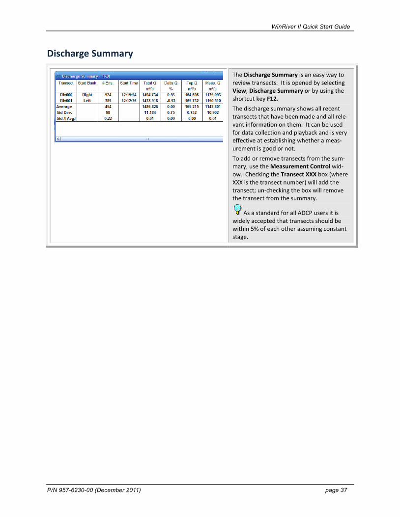
The Discharge Summary is an easy way to review transects. It is opened by selecting View, Discharge Summary or by using the shortcut key F12. The discharge summary shows all recent transects that have been made and all rele-vant information on them. It can be used for data collection and playback and is very effective at establishing whether a meas-urement is good or not. To add or remove transects from the sum-mary, use the Measurement Control wid-ow. Checking the Transect XXX box (where XXX is the transect number) will add the transect; un-checking the box will remove the transect from the summary.
As a standard for all ADCP users it is widely accepted that transects should be within 5% of each other assuming constant stage.
WinRiver II Quick Start Guide
page 38 Teledyne RD Instruments
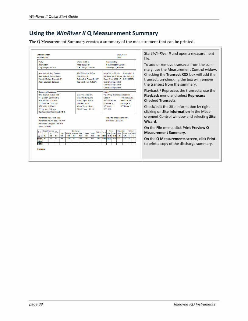
Using the WinRiver II Q Measurement Summary The Q Measurement Summary creates a summary of the measurement that can be printed.
Start WinRiver II and open a measurement file. To add or remove transects from the sum-mary, use the Measurement Control widow. Checking the Transect XXX box will add the transect; un-checking the box will remove the transect from the summary. Playback / Reprocess the transects; use the Playback menu and select Reprocess Checked Transects. Check/edit the Site Information by right-clicking on Site Information in the Meas-urement Control window and selecting Site Wizard. On the File menu, click Print Preview Q Measurement Summary. On the Q Measurements screen, click Print to print a copy of the discharge summary.
WinRiver II Quick Start Guide
P/N 957-6230-00 (December 2011) page 39
Print a Plot or Display
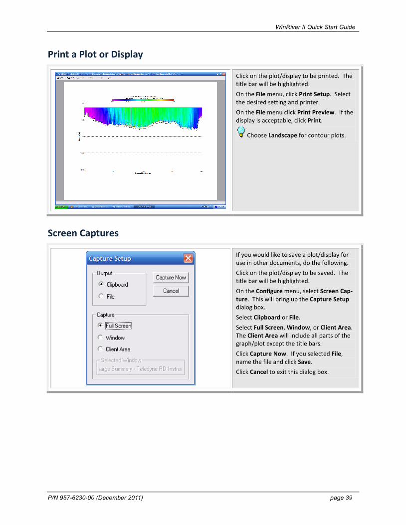
Click on the plot/display to be printed. The title bar will be highlighted. On the File menu, click Print Setup. Select the desired setting and printer. On the File menu click Print Preview. If the display is acceptable, click Print.
Choose Landscape for contour plots.
Screen Captures
If you would like to save a plot/display for use in other documents, do the following. Click on the plot/display to be saved. The title bar will be highlighted. On the Configure menu, select Screen Cap-ture. This will bring up the Capture Setup dialog box. Select Clipboard or File. Select Full Screen, Window, or Client Area. The Client Area will include all parts of the graph/plot except the title bars. Click Capture Now. If you selected File, name the file and click Save. Click Cancel to exit this dialog box.

WinRiver II Quick Start Guide
page 40 Teledyne RD Instruments
Water Profiling Modes This section explains all of the water-profiling modes available for the WorkHorse Rio Grande, Mariner ADCPs, and WorkHorse ADCPs with the high-resolution water profiling upgrade installed. For each mode, we provide a general description, an explanation of the best place to use this mode, specifics about the mode, and any setup considerations. Use Table 1 as a guide for choosing the appropriate mode for your water flow conditions.
Typically if the flow is slow and the depth is shallow you would first try Mode 11. If the flow were too fast or turbulent for Mode 11 you would use Mode 12 if fitted. If Mode 11 or Mode 12 is not suitable then Mode 1 will work in all but the most extreme situations. Mode 5 and Mode 8 are still included for backward compatibility and for users who are familiar and satisfied with their performance.
Table 1: Recommended River Water Profiling Modes Mode 1 Mode 12 Mode 11 Mode 13 Mode 5 Mode 8 Typical application Fast water of all
depths. Rough and dynamic situations. Good in streams too fast or deep for modes 5, 8 & 11 or where Mode 12 has problems.
Fast water of all depths. Good in streams too fast or deep for modes 5, 8 &11. Good for deep, slow water. See Note 1.
Slow, shallow streams with veloci-ties < 1.0 m/sec (depth dependant) with low shear and/or turbulence.
Slow, shallow streams where the Maximum Stream Depth is ≤ 1.0 meters and the Maximum Stream Velocity is < 0.25 m/s
Slow, shallow streams with veloci-ties < 0.5 m/sec with low shear and/or turbulence.
Shallow streams with velocities < 1 m/sec and with moderate shear (rough bed) and/or turbulence.
Minimum recommended cell size (meters)
0.50* 0.25
0.25* 0.10
0.10 0.05
Stre
amPr
o AD
CPs O
nly
See
Low
Noi
se M
ode/
Wat
er M
ode
13
0.10 0.10
0.10 0.10
Recommended Cell Size (meters)
0.50 0.25
0.25 0.10
0.25 0.05
0.25 0.10
0.25 0.10
Single ping standard deviation (cm/s) (using rec. cell size)
13.62 13.64
6.24 6.95
0.74 1.34
0.33 0.44
3.34 5.15
First range cell (meters) 0.97 0.51
0.73 0.26
0.49 0.09
0.49 0.14
0.49 0.14
Minimum profiling range (meters) Bottom Mode 5
1.7 1.0
1.7 1.0
1.6 0.9
1.6 0.9
0.9 0.6
Minimum profiling range (meters) Bottom Mode 7
NA 0.7
NA 0.5
NA 0.3
NA 0.7
NA 0.3
Maximum profiling range (meters)
73.1 19.55
68.29 15.82
<8.0 <4.0
<8.0 <4.0
<8.0 <4.0
Maximum relative velocity (m/s)
10 m/sec 10 m/sec 1 m/sec (Depth Depend-
ant)
0.5 m/sec 1 m/sec
* 600 kHz values are in bold font, and 1200 kHz values are in regular font. Specifications are for 25 cm blank (600 kHz), 5cm Blank (1200 kHz), 10° C temperature, and 0.0 salinity. Note 1. Mode 12 table assumes 20 sub-pings (WO20,4).
NOTE. The ranges in Table 1 are measured from the transducer face. Add the transducer depth to determine the actual minimum and maximum profiling depths.
NOTE. Maximum range depends on water temperature and depth cell size. Use PlanADCP to compute the maximum range for a particular ADCP set-up and water temperature. The standard deviation of modes 5, 8 and 11 varies with water speed, boat speed, bed-form roughness, channel depth, and turbulence.

WinRiver II Quick Start Guide
P/N 957-6230-00 (December 2011) page 41
Commonly Used ADCP Commands The commands shown in Table 2 (these are only a small percentage of those available) can all be found with detailed descriptions in the WorkHorse Commands and Output Data Format guide, however below are some of the more commonly used commands. Table 2: Commonly Used ADCP Commands Command Description
BX Max depth in decimeters (meters x 10) that the ADCP will look for the bottom - set this greater than your deepest depth.
WS Depth cell size (cm)
WN Number of depth cells (WS x WN = BX x 10)
WF Blanking distance (cm)
WV Ambiguity velocity (160 to 200 is usually good) (approximately water velocity in cm/sec)
WM Water mode 1, 5, 8, 11 or 12 (1200 Rio Grande / Zed Head)
WP Water pings
BP Bottom pings
CL Sleep Between Pings (CL0 = Do Not Sleep, CL1 = Sleep Between Pings)
Commonly Used BBTalk Commands Once BBTalk is running and connected to the ADCP, commands can be entered to interrogate the unit. The commands shown in Table 3 (these are only a small percentage of those available) can all be found with detailed descriptions in the WorkHorse Commands and Output Data Format guide.
Table 3: Commonly Used BBTalk Commands Command Description
CR1 Parameters set to FACTORY Settings
CK Parameters saved as USER defaults
PS0 Basic Instrument Information including Serial Number, Frequency, Firmware, and Board Serial Numbers
PT200 Built in Self Test
CB Change baud rate
PC1 Beam Continuity Test - Rub beams when asked to do so. ADCP must be in air to run this test.
PC2 Position, direction, temperature etc - Press any key to quit
PA Pre-deployment Tests
? List possible inputs. If added at the end of a command (i.e. CB?), it will list the command setting.
CS Start Pinging. Once ADCP is pinging, send a Break to stop.
= = = Send Break (Radio Modem)
End Send Break (Direct Cable)

WinRiver II Quick Start Guide
page 42 Teledyne RD Instruments
WinRiver II Shortcut Keys Key Description F1 Help F2 Reprocess transect F3 Configuration Setting F4 Start/Stop Pinging F5 Start/Stop Transect F6 Moving Bed Test F7 Properties F8 Toggle Bank F9 Toggle Ensemble Header Tabular view F11 Toggle Detailed Discharge/Composite Tabular view F12 Toggle Discharge Summary Tabular view Ctrl-A Output ASCII data file Ctrl-A Set as Active Configuration (when Measurement Control window selected) Ctrl-B Reference - Bottom Track Ctrl-C Copy Ctrl-D Toggle Acquire Control window Ctrl-E Close Measurement File Ctrl-F Create Measurement from Data Files Ctrl-F1 Apply to Checked Active Configurations Ctrl-F2 Apply to All Active Configurations Ctrl-F11 Select Stick (when Ship Track plot selected) Ctrl-F11 Add Transect (Playback) (when Measurement Control window selected) Ctrl-F11 Add Contour Pane (when Contour plot selected) Ctrl-F12 Remove Contour Pane (when Contour plot selected) Ctrl-F3 Toggle Measurement Management window Ctrl-F5 Reprocess Checked Transects Ctrl-F7 Properties (when window or file selected) Ctrl-F8 Data Selection (when Profile or Contour plot selected) Ctrl-F8 Transect Subsection (Playback) (when Measurement Control window selected) Ctrl-F9 Averaging Data Ctrl-G Reference - GPS (GGA) Ctrl-H Export as HYDROML Ctrl-U Duplicate Configuration node (when Measurement Control window selected) Ctrl-T Delete Configuration node (when Measurement Control window selected) Ctrl-J Rename Configuration node (when Measurement Control window selected) Ctrl-R Reset Configuration node Properties (when Measurement Control window selected) Ctrl-I Site Wizard Ctrl-K Add Note (when Measurement Control window selected) Ctrl-L Lock/Unlock Measurement File Ctrl-M View Command Log Ctrl-N Reference - None Ctrl-O Open measurement file Ctrl-P Print Ctrl-PgDn Scale Sticks Down (when Ship Track plot selected) Ctrl-PgUp Scale Sticks Up (when Ship Track plot selected) Ctrl-S Save Measurement File Ctrl-V Reference – GPS (VTG) Ctrl-W New Measurement Ctrl-Z Configuration Wizard Shift-F4 Set ADCP Clock Shift-F5 Reprocess Selected Transect Shift-F6 Reprocess Next Transect Shift-F8 Execute RGTest Shift-F9 Execute Pressure Sensor Test Shift-F10 Execute Compass Calibration Minus Previous Ensemble (Playback) Space Next Ensemble (Playback) Ctrl-Space Several Ensembles (Playback) Ctrl-Home Slider / Go to Ensemble (Playback) Home First Ensemble (Playback) End Last Ensemble (Playback)

WinRiver II Quick Start Guide
P/N 957-6230-00 (December 2011) page 43
Where to Find More Information Congratulations! You have completed the Quick Start Guide. For more detailed information, see the following sections in the WinRiver II User’s Guide.
Using the Measurement Wizard – This section covers how to create a configuration node using the Measurement Wizard and a detailed explanation of the configuration node settings.
Acquiring Discharge Data – This section is a more detailed explanation of the steps covered in the Quick Start Guide.
Post-Processing of Discharge Data – This section covers data playback, processing, and screen captures.
Integrating Depth Sounder, External Heading, and GPS Data – Use this section to integrate External head-ing, GPS data, and depth sounder data into your real-time discharge calculations. These devices are used when environmental conditions make it difficult to get unbiased boat velocity and/or depth using bottom tracking.
ADCP Commands – Use this section for a description of each command and guidelines for setting these commands to acquire reliable discharge data.
Water Profiling Modes – This section explains all of the water-profiling modes available for the Work-Horse Rio Grande, Mariner ADCPs, and WorkHorse ADCPs with the high-resolution water profiling upgrade installed. For each mode, we provide a general description, an explanation of the best place to use this mode, specifics about the mode, and any setup considerations.

WinRiver II Quick Start Guide
page 44 Teledyne RD Instruments
NOTES