Embed Size (px)
Citation preview

Software ManualWinSPS Help
Revision
3.21

WinSPS Help
Operating Manual
2002
by Bosch Rexroth AG, Erbach / GermanyAll rights reserved, including applications for protective rights.
Reproduction or handling over to third parties are subject to our written permission.


Contents I
1 Contents
1 Contents.........................................................................................................................................................I
2 Installation and License .............................................................................................................................2-12.1 Installation: From disk on the PC ...........................................................................................................2-12.1.1 License: From the demo version to the full version........................................................................2-12.2 Uninstallation: Removing the software from the harddisk .....................................................................2-1
3 What you should know before you start ....................................................................................................3-13.1 Calling up the WinSPS software ............................................................................................................3-13.2 Multiple calls of the WinSPS software ...................................................................................................3-13.3 Customizing the WinSPS software ........................................................................................................3-13.4 New project structure .............................................................................................................................3-23.5 Revision of existing PROFI projects ......................................................................................................3-23.6 Conversion of existing PROFI files ........................................................................................................3-33.7 Project presets .......................................................................................................................................3-43.8 Files of the WinSPS software.................................................................................................................3-53.9 Networking, multiple file accesses and read-only mode........................................................................3-73.10 Error messages of the WinSPS software...............................................................................................3-8
4 Operating Philosophy ................................................................................................................................4-14.1 Screen Layout ........................................................................................................................................4-14.2 Command selection ...............................................................................................................................4-34.3 Common keys for editor operation.........................................................................................................4-44.4 Mouse operation ....................................................................................................................................4-54.5 Mouse cursor symbols ...........................................................................................................................4-64.6 Special dialog boxes ..............................................................................................................................4-7
5 Introducing WinSPS...................................................................................................................................5-15.1 We create program examples together .................................................................................................5-15.2 Calling up the WinSPS software ............................................................................................................5-15.3 Quitting the WinSPS software................................................................................................................5-15.4 Presets and Licensing............................................................................................................................5-25.5 By the line: The Instruction List (Bosch IL) ............................................................................................5-65.5.1 Modules...........................................................................................................................................5-65.5.2 The first programming steps ...........................................................................................................5-65.5.3 The Symbol File ..............................................................................................................................5-95.5.4 Automatic Symbol Assignment .....................................................................................................5-115.5.5 Editing a data module ...................................................................................................................5-125.5.6 Summary: Editing..........................................................................................................................5-145.6 Connecting to the controller .................................................................................................................5-155.7 Loading the program into the controller ...............................................................................................5-155.8 Testing the program.............................................................................................................................5-165.8.1 Monitor - Your window into the controller .....................................................................................5-165.8.2 Programming cycle .......................................................................................................................5-165.9 So far, so good - how do we continue?................................................................................................5-175.9.1 Structure of the context help.........................................................................................................5-175.10 Current flow: The Ladder Diagram (LD) ..............................................................................................5-185.10.1 Preparation ...................................................................................................................................5-195.10.2 Normally-closed and normally-open contacts...............................................................................5-205.10.3 Series connection .........................................................................................................................5-225.10.4 Parallel connection........................................................................................................................5-245.11 Graphical combinations: Functional Block Diagram (FBD) .................................................................5-285.12 Step by Step: The Sequential Function Chart (SFC)...........................................................................5-285.12.1 MADAP or step marker technique? ..............................................................................................5-285.12.2 Table of contents ..........................................................................................................................5-295.12.3 The sequence ...............................................................................................................................5-29
II Contents
5.12.4 Step element ................................................................................................................................ 5-305.12.5 Alternative branch and empty step .............................................................................................. 5-315.12.6 Step action ................................................................................................................................... 5-355.12.7 Logical operation of a transition................................................................................................... 5-365.12.8 Markings in the sequence............................................................................................................ 5-375.12.9 Cyclical execution of the sequence ............................................................................................. 5-415.12.10 Create and load........................................................................................................................ 5-425.12.11 The SFC Monitor ...................................................................................................................... 5-435.13 Instruction List as per IEC 61131-3 (IEC IL) ....................................................................................... 5-455.13.1 Boolean operations ...................................................................................................................... 5-465.13.2 Boolean operations – Parentheses.............................................................................................. 5-485.13.3 Boolean operations – Nested parentheses ................................................................................. 5-495.13.4 Loading a program and more program examples ....................................................................... 5-525.14 Compact and clear: Structured Text (ST) ........................................................................................... 5-545.14.1 Declaring variables ...................................................................................................................... 5-555.14.2 Instructions................................................................................................................................... 5-585.14.3 Modules and module calls ........................................................................................................... 5-605.14.4 Project preparations..................................................................................................................... 5-605.14.5 Module call in conventional programming ................................................................................... 5-625.14.6 Creating and loading.................................................................................................................... 5-655.14.7 The ST Monitor ............................................................................................................................ 5-65
6 Programming ............................................................................................................................................ 6-16.1 Classic programming – Language elements, variables, data types ..................................................... 6-16.1.1 Character set.................................................................................................................................. 6-16.1.2 Numeric literals .............................................................................................................................. 6-26.1.3 String literals .................................................................................................................................. 6-36.1.4 Timer literals................................................................................................................................... 6-36.1.5 Data types ...................................................................................................................................... 6-46.1.6 Variables ........................................................................................................................................ 6-46.2 IEC 61131-3 – Program Organization Unit (POU)................................................................................ 6-66.2.1 Module types.................................................................................................................................. 6-66.2.2 Program block (PROGRAM).......................................................................................................... 6-76.2.3 Function block (FUNCTION_BLOCK) ........................................................................................... 6-86.2.4 Function (FUNCTION) ................................................................................................................... 6-96.2.5 Module calls ................................................................................................................................... 6-96.2.6 Layout of a POU........................................................................................................................... 6-106.3 IEC 61131-3 – Language elements, variables, data types................................................................. 6-116.3.1 Declaration of variables ............................................................................................................... 6-116.3.2 Elementary data types ................................................................................................................. 6-116.3.3 Generic data types....................................................................................................................... 6-126.3.4 Derived data types ....................................................................................................................... 6-136.3.5 Data type with limited value field.................................................................................................. 6-146.3.6 Enumerations ............................................................................................................................... 6-146.3.7 Arrays........................................................................................................................................... 6-156.3.8 Data structures............................................................................................................................. 6-156.3.9 Variables ...................................................................................................................................... 6-166.3.10 Directly represented variables ..................................................................................................... 6-166.3.11 Variable types .............................................................................................................................. 6-176.3.12 Attributes of variables .................................................................................................................. 6-186.4 IEC 61131-3 – Standard function blocks ............................................................................................ 6-206.4.1 SR: Flip-Flop with Set dominant .................................................................................................. 6-206.4.2 RS: Flip-Flop with Reset dominant .............................................................................................. 6-216.4.3 R_TRIG: Detection of the rising edge.......................................................................................... 6-216.4.4 F_TRIG: Detection of the falling edge ......................................................................................... 6-226.4.5 CTU: Up counter .......................................................................................................................... 6-226.4.6 CTD: Down counter ..................................................................................................................... 6-236.4.7 CTUD: Up and down counter....................................................................................................... 6-236.4.8 TP: Pulse...................................................................................................................................... 6-24

Contents III
6.4.9 TON: Switch-on delay ...................................................................................................................6-256.4.10 TOF: Switch-off delay ...................................................................................................................6-266.4.11 RTC: Set real-time clock...............................................................................................................6-27
7 Programming languages............................................................................................................................7-17.1 Instruction List (Bosch IL).......................................................................................................................7-27.2 Ladder Diagram (LD) .............................................................................................................................7-47.3 Function Block Diagram (FBD) ..............................................................................................................7-77.4 Sequential Function Chart (SFC)...........................................................................................................7-97.4.1 MADAP or step marker technique ................................................................................................7-107.4.2 Screen layout ................................................................................................................................7-107.4.3 SFC Table of contents ..................................................................................................................7-117.4.4 SFC sequence level......................................................................................................................7-137.4.5 SFC Swap-out...............................................................................................................................7-167.4.6 Create SFC project .......................................................................................................................7-167.5 Instruction List (IEC IL).........................................................................................................................7-177.5.1 Instructions....................................................................................................................................7-187.5.2 Current Result – CR......................................................................................................................7-197.5.3 IL sequences.................................................................................................................................7-217.5.4 Label .............................................................................................................................................7-217.5.5 Parenthesis ...................................................................................................................................7-227.5.6 Instruction set................................................................................................................................7-237.5.7 Load instructions – LD ..................................................................................................................7-257.5.8 Assignments – ST, S, R................................................................................................................7-267.5.9 Boolean operators – AND, &, OR, XOR .......................................................................................7-287.5.10 Arithmetic operators – ADD, SUB, MUL, DIV...............................................................................7-337.5.11 Comparison operators – GT, GE, EQ, LE, LT, NE .......................................................................7-357.5.12 Jump operators – JMP, JMPC, JMPCN .......................................................................................7-367.5.13 Call of function blocks – CAL, CALC, CALCN..............................................................................7-387.5.14 Call of functions ............................................................................................................................7-407.5.15 Return – RET, RETC, RETCN......................................................................................................7-427.6 Structured Text (ST).............................................................................................................................7-447.6.1 Creating an ST project ..................................................................................................................7-447.6.2 Instructions....................................................................................................................................7-457.6.3 Expressions and operators ...........................................................................................................7-467.6.4 Assignment ...................................................................................................................................7-477.6.5 IF instruction .................................................................................................................................7-477.6.6 CASE instruction...........................................................................................................................7-487.6.7 WHILE loop...................................................................................................................................7-497.6.8 REPEAT loop................................................................................................................................7-507.6.9 FOR loop.......................................................................................................................................7-517.6.10 EXIT instruction.............................................................................................................................7-527.6.11 Calling up function blocks .............................................................................................................7-527.6.12 Calling up functions.......................................................................................................................7-537.6.13 RETURN instruction......................................................................................................................7-547.7 IEC 61131-3 – Standard compliance ...................................................................................................7-557.7.1 Deviations an differences .............................................................................................................7-55
8 Presets.......................................................................................................................................................8-18.1 Project structure .....................................................................................................................................8-18.2 Directories ..............................................................................................................................................8-28.3 Projects ..................................................................................................................................................8-38.4 Settings ..................................................................................................................................................8-48.5 File names and connections to the controller ........................................................................................8-88.5.1 TCP/UDP/IP connection set-up and test ......................................................................................8-108.6 Buttons in the Presets dialog ...............................................................................................................8-108.6.1 Editor.............................................................................................................................................8-108.6.2 Monitor ..........................................................................................................................................8-118.6.3 Exit ................................................................................................................................................8-11

IV Contents
8.6.4 License......................................................................................................................................... 8-128.7 Additional functions by calling-up WinSPS ......................................................................................... 8-15
9 Editor......................................................................................................................................................... 9-19.1 Calling up the Editor .............................................................................................................................. 9-19.2 Screen layout ........................................................................................................................................ 9-29.3 Program module.................................................................................................................................... 9-39.3.1 Programming languages................................................................................................................ 9-39.3.2 Networks ........................................................................................................................................ 9-49.3.3 Symbolic operands ........................................................................................................................ 9-49.3.4 Input checks and symbol assignment............................................................................................ 9-59.4 Symbol file............................................................................................................................................. 9-59.5 Data module .......................................................................................................................................... 9-79.6 Text file .................................................................................................................................................. 9-89.7 Batch file................................................................................................................................................ 9-99.8 Documentation ...................................................................................................................................... 9-99.8.1 Printing of files................................................................................................................................ 9-99.8.2 Print layout ................................................................................................................................... 9-109.8.3 Control sequences in the module file........................................................................................... 9-109.8.4 Cross-reference list...................................................................................................................... 9-119.9 Stacker - Processing log ..................................................................................................................... 9-129.10 Connection to the PLC ........................................................................................................................ 9-129.11 Comparison ......................................................................................................................................... 9-139.12 Load program...................................................................................................................................... 9-139.13 Changing to the Monitor...................................................................................................................... 9-13
10 Editor – Menu functions .......................................................................................................................... 10-110.1 File Menu............................................................................................................................................. 10-110.1.1 New/Open .................................................................................................................................... 10-110.1.2 Save ............................................................................................................................................. 10-110.1.3 Save as ........................................................................................................................................ 10-110.1.4 Save all ........................................................................................................................................ 10-210.1.5 Insert file....................................................................................................................................... 10-210.1.6 Import symbols............................................................................................................................. 10-210.1.7 Compile module (ST) ................................................................................................................... 10-210.1.8 Check ........................................................................................................................................... 10-310.1.9 Create new project....................................................................................................................... 10-310.1.10 Generate file for download ....................................................................................................... 10-310.1.11 Compare entire program on disk with the PLC ........................................................................ 10-410.1.12 Compare all program modules on disk with the PLC............................................................... 10-410.1.13 Compare one program module on disk with the PLC .............................................................. 10-410.1.14 Compare two program modules on disk .................................................................................. 10-510.1.15 Compare one data module on disk with the PLC..................................................................... 10-610.1.16 Compare two data modules on disk......................................................................................... 10-610.1.17 Compile C module.................................................................................................................... 10-710.1.18 Create C library module ........................................................................................................... 10-710.1.19 Print program module file ......................................................................................................... 10-910.1.20 Print data module file.............................................................................................................. 10-1010.1.21 Print symbol file ...................................................................................................................... 10-1110.1.22 Print Sequential function chart ............................................................................................... 10-1110.1.23 Print layout.............................................................................................................................. 10-1210.1.24 Cross-reference...................................................................................................................... 10-1410.1.25 Create sequence .................................................................................................................... 10-1510.1.26 Change to module editor ........................................................................................................ 10-1610.1.27 Change to data module editor ................................................................................................ 10-1610.1.28 Change to symbol editor ........................................................................................................ 10-1610.1.29 Change to text editor .............................................................................................................. 10-1710.1.30 Properties ............................................................................................................................... 10-1710.1.31 File selector ............................................................................................................................ 10-17

Contents V
10.1.32 Exit.......................................................................................................................................... 10-1710.1.33 Back to sequence................................................................................................................... 10-1710.2 Edit Menu .......................................................................................................................................... 10-1810.2.1 Undo........................................................................................................................................... 10-1810.2.2 Redo........................................................................................................................................... 10-1810.2.3 Last Stacker result ..................................................................................................................... 10-1810.2.4 Repeat last command................................................................................................................ 10-1910.2.5 Cut.............................................................................................................................................. 10-1910.2.6 Copy........................................................................................................................................... 10-1910.2.7 Paste .......................................................................................................................................... 10-2010.2.8 Change IL to comments............................................................................................................. 10-2010.2.9 Change comments to IL............................................................................................................. 10-2010.2.10 Go to PLC instructions for step .............................................................................................. 10-2010.2.11 Go to FC <K_BETRA> ........................................................................................................... 10-2110.2.12 Insert pagination..................................................................................................................... 10-2110.2.13 Create/Delete diagnosis marker............................................................................................. 10-2110.2.14 Find......................................................................................................................................... 10-2210.2.15 Replace .................................................................................................................................. 10-2210.2.16 Find operand address (Single cross reference)..................................................................... 10-2310.2.17 Go to error line ....................................................................................................................... 10-2410.2.18 Go to PI no. ............................................................................................................................ 10-2410.2.19 Go to symbol definition........................................................................................................... 10-2410.2.20 Delete line in declaration table (ST) ....................................................................................... 10-2410.2.21 Global data types ................................................................................................................... 10-2510.2.22 Edit network title ..................................................................................................................... 10-2510.2.23 Insert before network ............................................................................................................. 10-2610.2.24 Insert after network................................................................................................................. 10-2610.2.25 Delete network ....................................................................................................................... 10-2610.2.26 Split network........................................................................................................................... 10-2610.2.27 Join with previous................................................................................................................... 10-2610.2.28 Join with next.......................................................................................................................... 10-2610.2.29 Create networks automatically ............................................................................................... 10-2710.2.30 Delete all network commands ................................................................................................ 10-2710.2.31 Create library module............................................................................................................. 10-2710.2.32 Call up parameter list ............................................................................................................. 10-2810.2.33 Edit parameter list .................................................................................................................. 10-2910.2.34 I/O configuration (OM3).......................................................................................................... 10-3110.3 View Menu......................................................................................................................................... 10-3410.3.1 Instruction List (IL) ..................................................................................................................... 10-3410.3.2 Ladder Diagram (LD) ................................................................................................................. 10-3410.3.3 Function Block Diagram (FBD) .................................................................................................. 10-3510.3.4 Sequential Function Chart (SFC)............................................................................................... 10-3510.3.5 Structured Text (ST) .................................................................................................................. 10-3510.3.6 Table of contents ....................................................................................................................... 10-3510.3.7 One level higher......................................................................................................................... 10-3510.3.8 Sequence title ............................................................................................................................ 10-3610.3.9 Overview .................................................................................................................................... 10-3610.3.10 Show sensitive fields.............................................................................................................. 10-3610.3.11 Change view: Auto <-> Manual branch.................................................................................. 10-3610.3.12 Symbolic/Absolute.................................................................................................................. 10-3610.3.13 Network line On/Off ................................................................................................................ 10-3610.3.14 Toolbar On/Off........................................................................................................................ 10-3710.3.15 ST Declaration tables............................................................................................................. 10-3810.3.16 Font ........................................................................................................................................ 10-3810.3.17 Colour selection...................................................................................................................... 10-3810.4 Toolbox Menu – LD........................................................................................................................... 10-3910.4.1 Edit mode................................................................................................................................... 10-3910.4.2 Normally-open contact............................................................................................................... 10-4010.4.3 Normally-closed contact ............................................................................................................ 10-40

VI Contents
10.4.4 Connection ................................................................................................................................. 10-4010.4.5 Assignment (coil) ....................................................................................................................... 10-4110.4.6 Set (S) ........................................................................................................................................ 10-4110.4.7 Reset (R).................................................................................................................................... 10-4210.4.8 Timer – Pulse (SI) ...................................................................................................................... 10-4210.4.9 Timer – Extended Pulse (SV) .................................................................................................... 10-4210.4.10 Timer – Switch-on delay (SE) ................................................................................................ 10-4310.4.11 Timer – Remanent switch-on delay (SS) ............................................................................... 10-4310.4.12 Timer – Switch-off delay (SA)................................................................................................. 10-4410.4.13 Timer – Stop (TH)................................................................................................................... 10-4510.4.14 Timer – Reset (RT)................................................................................................................. 10-4510.4.15 Set Counter (SZ) .................................................................................................................... 10-4510.4.16 Up Counter (CU) .................................................................................................................... 10-4510.4.17 Down Counter (CD)................................................................................................................ 10-4610.4.18 Reset Counter (RZ) ................................................................................................................ 10-4610.4.19 Jump at RLO = 1 (JPC).......................................................................................................... 10-4610.4.20 Jump at RLO = 0 (JPU).......................................................................................................... 10-4610.4.21 Module Call at RLO = 1 (CMC) .............................................................................................. 10-4710.4.22 Module Call at RLO = 0 (CMU) .............................................................................................. 10-4710.4.23 Call of a second data module at RLO = 1 (MXC)................................................................... 10-4710.4.24 Call of a second data module at RLO = 0 (MXU)................................................................... 10-4810.4.25 End of module at RLO = 1 (EMC) .......................................................................................... 10-4810.4.26 End of module at RLO = 0 (EMU) .......................................................................................... 10-4810.4.27 Shift Right ............................................................................................................................... 10-4810.4.28 Shift Down .............................................................................................................................. 10-4910.4.29 Insert Branch – Before ........................................................................................................... 10-4910.4.30 Insert Branch – After .............................................................................................................. 10-4910.4.31 Delete Branch......................................................................................................................... 10-5010.4.32 Check Branch......................................................................................................................... 10-5010.5 Toolbox Menu – FBD ........................................................................................................................ 10-5110.5.1 And (&) ....................................................................................................................................... 10-5110.5.2 Or (>=1)...................................................................................................................................... 10-5110.5.3 Insert FBD pin ............................................................................................................................ 10-5110.5.4 Delete FBD pin........................................................................................................................... 10-5110.5.5 Negate FBD pin.......................................................................................................................... 10-5210.5.6 Exclusive Or (=1) ....................................................................................................................... 10-5210.5.7 SR flip-flop.................................................................................................................................. 10-5210.5.8 RS-Flip-Flop ............................................................................................................................... 10-5210.5.9 Timer - Pulse (SP) ..................................................................................................................... 10-5310.5.10 Timer - Extended Pulse (SPE) ............................................................................................... 10-5410.5.11 Timer - Start-up delay (SR) .................................................................................................... 10-5410.5.12 Timer - Remanent start-up delay (SRE)................................................................................. 10-5510.5.13 Timer - Shut-down delay (SF) ................................................................................................ 10-5610.5.14 Up Counter (CU) .................................................................................................................... 10-5610.5.15 Down Counter (CD)................................................................................................................ 10-5710.5.16 Up/Down Counter (CU&CD) .................................................................................................. 10-5710.5.17 Comparator - Equal ................................................................................................................ 10-5810.5.18 Comparator - Not equal.......................................................................................................... 10-5810.5.19 Comparator - Greater than..................................................................................................... 10-5810.5.20 Comparator - Greater than or equal....................................................................................... 10-5910.5.21 Comparator - Less than.......................................................................................................... 10-5910.5.22 Comparator - Less than or equal ........................................................................................... 10-6010.5.23 Jump at RLO = 1 (JPC).......................................................................................................... 10-6010.5.24 Jump at RLO = 0 (JPU).......................................................................................................... 10-6010.5.25 Module call at RLO = 1 (CMC) ............................................................................................... 10-6010.5.26 Module call at RLO = 0 (CMCI) .............................................................................................. 10-6110.5.27 End of module at RLO = 1 (EMC) .......................................................................................... 10-6110.5.28 Output assignment (=)............................................................................................................ 10-6110.6 Toolbox Menu SFC ........................................................................................................................... 10-62

Contents VII
10.6.1 Swap out .................................................................................................................................... 10-6210.6.2 Swap in ...................................................................................................................................... 10-6310.6.3 Insert sequence ......................................................................................................................... 10-6310.6.4 Insert description........................................................................................................................ 10-6310.6.5 Transition/Step........................................................................................................................... 10-6410.6.6 Simultaneous branch ................................................................................................................. 10-6510.6.7 Alternative branch ...................................................................................................................... 10-6510.6.8 Loop ........................................................................................................................................... 10-6610.6.9 Jump .......................................................................................................................................... 10-6710.6.10 Step action - Non-remanent (=) ............................................................................................. 10-6710.6.11 Step action - Reset with priority (R) ....................................................................................... 10-6810.6.12 Step action - Remanent (S).................................................................................................... 10-6810.6.13 Step action - With time limit (SP) ........................................................................................... 10-6810.6.14 Step action - With delay (SR)................................................................................................. 10-6810.6.15 Step action - Remanent with time limit (SPE) ........................................................................ 10-6910.6.16 Step action - Remanent with delay (SRE) ............................................................................. 10-6910.6.17 Step action - Set counter (SC) ............................................................................................... 10-6910.6.18 Step action - Reset counter (RC) ........................................................................................... 10-7010.6.19 Step action - Increment counter (CU) .................................................................................... 10-7010.6.20 Step action - Decrement counter (CD)................................................................................... 10-7010.6.21 Step action - Module call (CMC) ............................................................................................ 10-7010.6.22 Step action - PLC instructions................................................................................................ 10-7110.6.23 AND transition ........................................................................................................................ 10-7210.6.24 OR transition .......................................................................................................................... 10-7210.6.25 Negation ................................................................................................................................. 10-7210.6.26 Comment................................................................................................................................ 10-7310.6.27 Sequence/Step parameters (MADAP only) ........................................................................... 10-7310.6.28 Copy automatic conditions to the manual branch.................................................................. 10-7410.6.29 Options ................................................................................................................................... 10-7510.7 Control Menu..................................................................................................................................... 10-7710.7.1 Load ........................................................................................................................................... 10-7710.7.2 Unload........................................................................................................................................ 10-7810.7.3 Load date and time .................................................................................................................... 10-7910.7.4 Load firmware ............................................................................................................................ 10-7910.7.5 Compare firmware ..................................................................................................................... 10-8010.7.6 Save program to EPROM .......................................................................................................... 10-8010.7.7 Save program to Memory Card ................................................................................................. 10-8110.7.8 Load program from Memory Card ............................................................................................. 10-8110.7.9 Save program to System ........................................................................................................... 10-8110.7.10 Load program from System.................................................................................................... 10-8110.7.11 Memory dump ........................................................................................................................ 10-8110.7.12 Delete memory ....................................................................................................................... 10-8110.7.13 Start-up mode......................................................................................................................... 10-8210.7.14 Run......................................................................................................................................... 10-8210.7.15 Stop ........................................................................................................................................ 10-8210.7.16 Infostatus................................................................................................................................ 10-8210.7.17 Reference list ......................................................................................................................... 10-8310.7.18 Interface test........................................................................................................................... 10-8310.7.19 System Coordinator (SK Table) ............................................................................................. 10-8310.7.20 Load date and time................................................................................................................. 10-8610.7.21 Protocol loader ....................................................................................................................... 10-8610.7.22 Profibus Projecting ................................................................................................................. 10-8610.7.23 Load Ethernet projects ........................................................................................................... 10-8710.7.24 Load IP address ..................................................................................................................... 10-8810.7.25 Load MAP projecting data...................................................................................................... 10-8910.7.26 Central Programming ............................................................................................................. 10-9010.8 Change Menu.................................................................................................................................... 10-9410.8.1 Monitor ....................................................................................................................................... 10-9410.8.2 Load + Monitor ........................................................................................................................... 10-94

VIII Contents
10.8.3 Presets ....................................................................................................................................... 10-9510.9 Help Menu ......................................................................................................................................... 10-9610.9.1 Contents..................................................................................................................................... 10-9610.9.2 Software Service........................................................................................................................ 10-9610.9.3 Info ............................................................................................................................................. 10-97
11 Monitor .................................................................................................................................................... 11-111.1 Calling up the Monitor ......................................................................................................................... 11-111.2 Module check ...................................................................................................................................... 11-211.3 Connection to the PLC ........................................................................................................................ 11-211.4 Multiple calls........................................................................................................................................ 11-211.5 Screen layout ...................................................................................................................................... 11-311.6 Program module.................................................................................................................................. 11-411.6.1 Programming language................................................................................................................ 11-411.6.2 Instruction List (IL) ....................................................................................................................... 11-411.6.3 Ladder Diagram (LD) ................................................................................................................... 11-611.6.4 Function Block Diagram (FBD) .................................................................................................... 11-611.6.5 Sequential Function Chart (SFC)................................................................................................. 11-711.7 Data module ........................................................................................................................................ 11-811.8 Text file ................................................................................................................................................ 11-911.9 Operand field....................................................................................................................................... 11-911.10 Data field........................................................................................................................................ 11-1211.11 Forcing........................................................................................................................................... 11-1411.12 Trigger - Tracing program and data access .................................................................................. 11-16
12 Monitor – Menu functions ....................................................................................................................... 12-112.1 File Menu............................................................................................................................................. 12-112.1.1 Open ............................................................................................................................................ 12-112.1.2 Save ............................................................................................................................................. 12-112.1.3 Save as ........................................................................................................................................ 12-112.1.4 Save all ........................................................................................................................................ 12-212.1.5 Insert file....................................................................................................................................... 12-212.1.6 Change to module monitor........................................................................................................... 12-212.1.7 Change to data module monitor .................................................................................................. 12-212.1.8 Change to text editor.................................................................................................................... 12-212.1.9 Change to operand field editor .................................................................................................... 12-212.1.10 Change to data field editor ....................................................................................................... 12-212.1.11 Change to forcing editor ........................................................................................................... 12-212.1.12 File selector .............................................................................................................................. 12-212.1.13 Exit............................................................................................................................................ 12-212.2 Edit Menu ............................................................................................................................................ 12-312.2.1 Undo............................................................................................................................................. 12-312.2.2 Redo............................................................................................................................................. 12-312.2.3 Cut................................................................................................................................................ 12-312.2.4 Copy............................................................................................................................................. 12-412.2.5 Paste ............................................................................................................................................ 12-412.2.6 Find .............................................................................................................................................. 12-412.2.7 Find operand address (Single cross reference) .......................................................................... 12-412.2.8 Go to error line ............................................................................................................................. 12-412.2.9 Go to PI no. .................................................................................................................................. 12-412.2.10 Go to absolute program address.............................................................................................. 12-512.3 View Menu........................................................................................................................................... 12-612.3.1 Instruction List (IL) ....................................................................................................................... 12-612.3.2 Ladder Diagram (LD) ................................................................................................................... 12-612.3.3 Function Block Diagram (FBD) .................................................................................................... 12-612.3.4 Sequential Function Chart (SFC)................................................................................................. 12-712.3.5 Structured Text (ST) .................................................................................................................... 12-712.3.6 Table of contents ......................................................................................................................... 12-712.3.7 One level higher........................................................................................................................... 12-7

Contents IX
12.3.8 Sequence title ...............................................................................................................................12-812.3.9 Edit ................................................................................................................................................12-812.3.10 Display.......................................................................................................................................12-812.3.11 Control .......................................................................................................................................12-812.3.12 Flag............................................................................................................................................12-812.3.13 Load...........................................................................................................................................12-812.3.14 Format .......................................................................................................................................12-912.3.15 Symbolic/Absolute.................................................................................................................. 12-1012.3.16 Network line On/Off ................................................................................................................ 12-1012.3.17 Toolbar On/Off........................................................................................................................ 12-1012.3.18 Trace from cursor line ............................................................................................................ 12-1012.3.19 Overview ................................................................................................................................ 12-1112.3.20 Show timer and counter values.............................................................................................. 12-1112.3.21 Font ........................................................................................................................................ 12-1112.3.22 Color ....................................................................................................................................... 12-1112.4 Control Menu..................................................................................................................................... 12-1212.4.1 Run............................................................................................................................................. 12-1212.4.2 Stop............................................................................................................................................ 12-1212.4.3 Enable outputs ........................................................................................................................... 12-1212.4.4 Disable outputs .......................................................................................................................... 12-1212.4.5 Change module one level Down (Plus) ..................................................................................... 12-1212.4.6 Change module one level Up (Minus) ....................................................................................... 12-1312.4.7 Infostatus.................................................................................................................................... 12-1312.4.8 Configuration diagram................................................................................................................ 12-1312.4.9 Reference list ............................................................................................................................. 12-1412.4.10 Load forcing file ...................................................................................................................... 12-1412.4.11 Unload forcing file................................................................................................................... 12-1412.4.12 Trigger activate program module ........................................................................................... 12-1412.4.13 Trigger deactivate program module ....................................................................................... 12-1512.4.14 Trigger display program module ............................................................................................ 12-1512.4.15 Trigger Operand Address....................................................................................................... 12-1512.4.16 Synchronize to cascade no. ................................................................................................... 12-1512.4.17 Central Programming ............................................................................................................. 12-1612.5 Change Menu.................................................................................................................................... 12-1712.5.1 Editor.......................................................................................................................................... 12-1712.5.2 Presets ....................................................................................................................................... 12-17
13 Communications and networked systems...............................................................................................13-113.1 Project configurator ..............................................................................................................................13-113.1.1 System-wide communications ......................................................................................................13-113.1.2 Program call ..................................................................................................................................13-213.1.3 Creating and editing a project.......................................................................................................13-313.1.4 Control tree - Configuring the system...........................................................................................13-413.1.5 Front Side and Back Side .............................................................................................................13-513.1.6 IP addressing ................................................................................................................................13-613.1.7 Subnet mask .................................................................................................................................13-713.1.8 Ethernet settings ...........................................................................................................................13-913.1.9 Checking and enabling a system configuration............................................................................13-913.1.10 File menu – Create configuration file ..................................................................................... 13-1013.1.11 File menu – Open configuration file ....................................................................................... 13-1113.1.12 File menu – Save configuration file ........................................................................................ 13-1113.1.13 File menu – Save configuration file as ................................................................................... 13-1213.1.14 File menu – Merge configuration files .................................................................................... 13-1213.1.15 File menu – Print .................................................................................................................... 13-1213.1.16 File menu – Print preview....................................................................................................... 13-1313.1.17 File menu – Print options ....................................................................................................... 13-1313.1.18 File menu – End ..................................................................................................................... 13-1313.1.19 View menu – Toolbar ............................................................................................................. 13-1313.1.20 View menu – Status bar ......................................................................................................... 13-13

X Contents
13.1.21 Tools menu – Insert................................................................................................................ 13-1313.1.22 Tools menu – Delete .............................................................................................................. 13-1413.1.23 Tools menu – Show one level ................................................................................................ 13-1413.1.24 Tools menu – Show all ........................................................................................................... 13-1413.1.25 Tools menu – Hide (one level) ............................................................................................... 13-1413.1.26 Tools menu – Find.................................................................................................................. 13-1413.1.27 Tools menu – Go to next error ............................................................................................... 13-1413.1.28 Configuration menu – Load.................................................................................................... 13-1513.1.29 Configuration menu – Scan.................................................................................................... 13-1713.1.30 Configuration menu – Simple comparison with PLC.............................................................. 13-1813.1.31 Configuration menu – Detailed comparison with PLC ........................................................... 13-1813.1.32 Configuration menu – Detailed comparison with file.............................................................. 13-1913.1.33 Configuration menu – Check.................................................................................................. 13-1913.1.34 Configuration menu – Load copy ........................................................................................... 13-1913.1.35 Configuration menu – Unload copy........................................................................................ 13-2013.1.36 Ethernet menu – Edit parameters .......................................................................................... 13-2013.1.37 IP Addresses menu – Define ................................................................................................. 13-2213.1.38 Project protection menu – Change system protection ........................................................... 13-2313.1.39 Project protection menu – Edit system password .................................................................. 13-2413.1.40 Presets menu ......................................................................................................................... 13-2413.1.41 Presets menu – General ........................................................................................................ 13-2513.1.42 Presets menu – IP address range.......................................................................................... 13-2513.1.43 Presets menu – Check function ............................................................................................. 13-2613.1.44 Presets menu – Print set-up................................................................................................... 13-2613.1.45 Help menu – Contents............................................................................................................ 13-2613.1.46 Help menu – Info .................................................................................................................... 13-2713.2 Central programming ........................................................................................................................ 13-2813.2.1 Prerequisites .............................................................................................................................. 13-2913.2.2 Functionality and limitations....................................................................................................... 13-2913.2.3 Preparations - Installing the PROFIboard.................................................................................. 13-3013.2.4 Preparations - Bus configuration ............................................................................................... 13-3113.2.5 Presets ....................................................................................................................................... 13-3213.2.6 Current information .................................................................................................................... 13-3313.2.7 Troubleshooting ......................................................................................................................... 13-33
14 PCL – The Control in the PC .................................................................................................................. 14-114.1 Installation ........................................................................................................................................... 14-114.2 Starting ................................................................................................................................................ 14-214.3 Projecting with WinSPS ...................................................................................................................... 14-214.4 Troubleshooting................................................................................................................................... 14-4

Contents XI


Installation and License 2-1
2 Installation and License
2.1 Installation: From disk on the PC
The WinSPS software (Order no. 077 925) is supplied on floppy disks orCD-ROM or can be obtained via modem from the Bosch mailbox (seemenu item ‘Help’, ‘Software Service’).
Detailed installation instructions are contained in the file: SET-UPE.DOC
You will find the document READPLC.DOC after installation. This filecontains last minute changes and corrections which could not be in-cluded in WinSPS-Help or in the control manuals, due to lack of time.Please read this file very carefully.
2.1.1 License: From the demo version to the full version
Following the installation of the WinSPS software it is necessary to li-cense it. License will make you a registered user who has legally pur-chased WinSPS and is entitled to use it. Previously - in the PROFIsoftware - the right to use was proved by the existence of a dongle. Thisdongle is no longer used with the WinSPS software and has been re-placed with the license.
You can find additional information by using the help functions for thepreset menu ‘License’ and in the file READPLC.DOC.
2.2 Uninstallation: Removing the software from the harddisk
If you ever want to remove the WinSPS software from your harddisk, youshould do this with the included uninstaller program: ‘Uninstall WinSPS’.The installer ensures that only the installed files are deleted. Of course,the project files which you have created with WinSPS will remain un-touched.
Important: The directory where WinSPS was installed is retained for thefollowing reasons:
a. You can easily return to the previous state: Simply install the softwareagain in the same directory.
b. The license is not lost (the secret files which contain the license infor-mation are not deleted: WINSPS.ENT, WINSPS.KEY, and WINSPS.RST)
If you did not delete the software with ‘Uninstall’:In this case, a "vacant software entry" is left in the Windows control panel'Software'. To delete this entry, you have to proceed as follows:
1 Start the Windows Registry editor (Windows Menu: 'Execute') Re-gedit

Installation and License2-2
2 Open the following folders one after the other:HKEY_LOCAL_MACHINESOFTWAREMicrosoftWindowsCurrentVersionUninstall
3 Select the entry which has to be deleted, e.g.
and delete the entry with
Do not delete entries except the "vacant" WinSPS and WinDPkeys, respectively
4 Close the registry editor

What you should know before you start 3-1
3 What you should know before you start
3.1 Calling up the WinSPS software
The installer program creates the program group: ‘Bosch’ on the Win-dows desktop which you can access via the ‘Start’ menu and ‘Programs’.There you will find the button for the WinSPS software, among otherthings.
3.2 Multiple calls of the WinSPS software
The WinSPS software can be started more than once. This allows you toedit several files - which can even belong to different projects - simulta-neously or view them in the Monitor.
Multiple calls of a software are often not intended by unexperienced us-ers. If you start the WinSPS software and an active copy already exists inthe memory, a dialog box will appear to notify you of this condition. Youcan then choose whether you want to switch to the already active copy orwhether you want to start the software once more. If desired, this dialogbox can be suppressed with the function switch /d.
3.3 Customizing the WinSPS software
The WinSPS software can be customized via function switches. Theseswitches can be entered both in the command line and in the start-up fileWINSPS.INI before you start the software. You will find a complete list ofthe switches in chapter ‘Presets, ‘Parameters’.
By calling up the WinSPS software for the first time, the following defaultsettings are made: /A /B /C /D /F4 /I /K59 /T /U1.
Switches in the command lineThe switches described above can be entered in the command line,separated by commas.
Switches in the start-up fileEach switch can be written into the start-up file WINSPS.INI. This filemust reside in the WinSPS directory (program directory). In case of du-plicate entries, the parameters in the command line may overwrite switchsettings in the start-up file.
A parameter can be entered in each line of the start-up file. This pa-rameter must be the very beginning of each line. Comments can be in-troduced with a semicolon.
Example:
; File: WINSPS.INI/c ;no copyright message at start-up/b ;no backup messages when saving

What you should know before you start3-2
In case of incorrect switches, a warning will be displayed when theWinSPS software is called, and all subsequent switches will be ignored.
The current function switch settings can be viewed in the main menu viathe menu function ‘Settings’, ‘Parameters’.
3.4 New project structure
The new project structure allows the management of several controllerswithin one project. Previously, there was a one-to-one relationship be-tween projects and controllers.
Project structure of the PROFI software:
New project structure of the WinSPS software:
In addition, each ZS directory is followed by a WORK directory. This isused to store the working files which have been optimized by theWinSPS software.
3.5 Revision of existing PROFI projects
The module and symbol files to be revised must have been createdwith PROFI software version 3.0 or later. Older versions need to beconverted first using a current version of the PROFI software.

What you should know before you start 3-3
Before you edit existing PROFI projects in WinSPS, you will need to cre-ate a new project structure and copy the PROFI projects into this struc-ture. In the PROFI software, the file type was encoded in the controllertype. WinSPS does not use this encoding (e. g.: *.P5O for CL500, *.PBOfor CL200, *.PCO for CL400 becomes the general type *.PXO inWinSPS). The file type needs to be changed manually before the conver-sion is made .
Moreover, the PROFI project must be present in the same language asthe currently selected Windows language setting. If the languages aredifferent, the project can be converted using function switch /S... for thelanguage setting.
When the WinSPS Editor or Monitor is called, all files (except for librarymodules, see below) are converted into a new file format which is suit-able for Windows.
Following this operation, is will no longer be possible to edit theproject with the PROFI software. Please create a backup copy priorto project conversion if required.
Special rules apply to the revision of library modules .
3.6 Conversion of existing PROFI files
The conversion is made automatically when the Editor or the Monitor iscalled. Conversion results in the following changes (for more explana-tions see chapter ‘Editor’, ‘Language Set’):
Program modulesOnly correctly assigned program modules are converted into the newformat. The file structure is largely preserved. Conversion is made intothe extended IEC 1131-3 format. Non-conforming characters are re-placed with IEC 1131-3-conforming designators. Some special charactesare replaced as follows:
PROFI Software WinSPS+ (termination) _PLUS+ (embedded) _ (single underscore)- (termination) _MINUS- (embedded) _ (single underscore)% _PERCENTother _ (single underscore)
The operand attribute is adapted according to IEC 1131-3:
Attribute for PROFI WinSPSBit BByte BY BWord W W

What you should know before you start3-4
For parameters, the previous default attribute (<TAB> instead of operandattribute) changes form Word to Bit.
Bit operands are replaced with byte operands unless they are used in bit-only instructions.
Symbol fileThe file is converted into the ASCII format. This means that the symbolfile is no longer format-dependent and can be created and edited withany standard ASCII editor.
The memory ID R/E is appended to the absolute module name, sepa-rated by a comma.
II/IO and EI/EO operands are word operands in WinSPS, not bit oper-ands.
Symbols are converted into IEC 1131-3-conforming designators (seeprogram modules).
Symbols on byte boundaries are entered twice. The additional symbol isappended with a _B. This symbol can be used to make byte, word anddouble-word accesses.
Data modulesAll data modules are extracted from the symbol file. Each data module isstored as a data module file under its symbolic name and the file type.PXD.
Symbolically addressed data fields are appended to the symbol file as aglobal constant definition.
Conversion is made into the extended IEC 1131 format.
ASCII data fields are converted into the IEC 1131-3-conforming data typeSTRING.
Operand field/data field fileOperand field and data field files cannot be transferred into WinSPS.These files need to be newly created!
All other files are not changed by the WinSPS software.
3.7 Project presets
After the WinSPS software has been called up, the system looks for theproject path. If a project path has not yet been specified, a dialog box willnotify you of this condition, and the current program directory is used asthe project path.
The project path can be altered in the presets (main menu).

What you should know before you start 3-5
When you exit from the WinSPS software, status files are stored in thecontroller status file. These files contain the project and controller pre-sets, the current color and font settings of the editors, the current screenpositions and the size of the WinSPS window. The status data will beread when WinSPS is started again. This means that the settings of theprevious call are always reconstructed.
3.8 Files of the WinSPS software
Most files and directories are created automatically by the WinSPS soft-ware based on the presets.
Contrary to the PROFI software, no controller type is encoded with thefile type. Instead, the letter X is always used (e. g. the PROFI programmodule file of a CL500 with file type *.P5O is given the name *.PXO inthe WinSPS software).
During execution of WinSPS, the following files are accessed.
Files in the ZS directory:The ZS directory contains all files which are associated with the currentcentral processing unit. The WinSPS software must be able to makewrite accesses to this directory.
*.PXO Program module file; this file contains line control bytes.Changes are only allowed in the Module Editor.
*.PXL Library module file; this protected program module file con-tains executable machine code.
*.AS SFC file; this file is edited in the module editor in the Se-quential function chart (SFC) programming language.
*.ST ST file; this file is edited in the module editor in der Struc-tured Text (ST) programming language.
*.PXD Data module file; this file is edited in the Data Module Editor(ASCII format).
*.SXS Symbol file; this file is edited in the Symbol Editor (ASCIIformat).
*.OXD Operand field file (ASCII format)
DFELD.DXD Data field file (ASCII format); only one data field filewith the fixed name DFELD.DXD exists within one centralprocessing unit.
FIXIER.FXD Forcing file (ASCII format); only one forcing file with thefixed name FIXIER.FXD exists within one central processingunit.
*.WSP Controller state file (default name: PROJECT.WSP); this filereplaces the former PROJECT.SPS of the PROFI software.Different controller state files can be used for example to al-low individual presets for different editors of a PLC projecton a single computer.
*.QV Cross-reference file (ASCII format)
*.STP Batch file (ASCII format)
*.BAK Backup file; WinSPS creates backup files for safety reasons.The creation of these files can be suppressed with the func-tion switch /b.

What you should know before you start3-6
*.DOC, *.LST, *.PRNText files (ASCII format)
Files in the library directory:The library directory (BOSCH.BIB) can be used to store all programmodules for several projects. Files in this directory are available for dif-ferent projects . Each controller type requires a separate library di-rectory. You can use a common library directory for the controllersCL350, CL400, and CL500. Files in this directory are of the read-onlytype; the WinSPS software must be able to make read accesses to thisdirectory:
*.PXO Program module file; this file contains line control bytes.Changes are only allowed in the module editor.
*.PXL Library module file; this protected program module file con-tains executable machine code.
Files in the SK directory (CL400 and CL500 only):The SK directory contains the files associated with the current systemcoordinator. The WinSPS software must be able to make write accessesto this directory.
SK.SXK SK table; this files is automatically created and managed bythe WinSPS software when the SK table is edited.
This directory also contains the files for the transfer (protocol loader) andProfibus protocols (Profibus loader).
Files in the project directory (for Central Programming only):Two files are necessary for the Central Programming. They are madewith the help of the PROFIBUS configurator. The WinSPS Softwarereads these files from the project directory.
*.BUS Bus parameter file; this file contains important performancedata for the PROFIBUS system.
*.TOP Topology file; this file contains the structure of the PRO-FIBUS network.
Files in the project configurator directory:The project configurator is an editing program which is called up via theproject presets of the WinSPS. The project configurator creates the di-rectory “_Config_CL550” in parallel with the project path. This directory isused to store the configuration files.
*.PCF Configuration file: In this file, networked systems are definedand edited in order to group a linked number of controllers oftype CL550 that can communicate with each other.
Files in the WORK directory:The WinSPS software creates and appends an internal WORK directoryto each ZS directory. This directory is used to store optimized workfiles.The WinSPS software must be able to make write accesses to thisdirectory.
*.PXA Loadable program module file (opcode); this file is automati-cally created by the WinSPS software and must not be al-tered.

What you should know before you start 3-7
*.SXA Symbol check file; this file is automatically created by theWinSPS software and must not be altered.
*.PXQ Optimized internal cross-reference file; this file is automati-cally created by the WinSPS software and must not be al-tered.
*.EST The WinSPS software uses this file to log all error messagesor warnings which have been detected using the ‘Compile‘or ‘Create new project ‘ function. The file has the samename as the associated ST file.
DFELD.DXA Data field file opcode; this file is automatically createdby the WinSPS software and must not be altered.
Files in the temporary directory (TMP):The temporary directory is used by the WinSPS software to store tempo-rary work files. WinSPS reads the path specification from the user envi-ronment specification "TMP“. The variable is specified in the program‘System settings’ under the program group ‘System controls’. TheWinSPS software must be able to make write accesses to this directory.
*.TMP Residues of temporary files after a system crash. These filesmay be deleted. However, it will be necessary to exitWinSPS first.
_WINSPS_.ERRThis file is used by the WinSPS software to log all fatal er-rors that may have occurred. The file may be deleted if re-quired.
3.9 Networking, multiple file accesses and read-only mode
Owing to the increasing complexity of automation projects, it is oftennecessary that several PLC programmers work on one project at thesame time. For this purpose, the WinSPS software provides the neces-sary interlocking mechanisms for parallel access to project files.
Since Windows itself is a multitasking operating system, there is the ad-ditional possibility to make multiple calls of the WinSPS software on oneworkstation and to run it in separate windows on the screen. This is whenthe software must allow simultaneous, controlled accesses to projectfiles.
Moreover, a customizable editing performance is often desired. For ex-ample, it can be required to prevent maintenance staff from altering mod-ule or symbol files (read-only mode).
Another option to restrict the editing capabilities is to block changes tothe program code. Only changes to comments are allowed. This can pre-vent inadvertent program changes during language conversions of a PLCprogram.
For these purposes, the WinSPS software provides corresponding cus-tomizing options (see also paragraph ‘Customizing WinSPS’ in thischapter). In the standard configuration, all files are opened as usual inRead/Write mode. In case of conflicts, dialog boxes will be displayed:

What you should know before you start3-8
Same file opened twice for writingYou are notified that the file is already being edited. It is possible to openthe file in read-only mode in which changes cannot be made to the file. Ifthe file is opened in read and write mode, a copy of the file is created.This copy can be edited. When you try to save the file, another dialog boxwill ask you if you want to overwrite the original file or save the copy un-der a new name.
Opening a write-protected file in write modeYou are notified that the file is opened in read-only mode. No changesare possible.
3.10 Error messages of the WinSPS software
If undefined program states occur during program execution or if the op-erating system reports a malfunction, WinSPS will create a unique, self-explanatory error message in a dialog box.
In addition to the screen output, a file _WINSPS_.ERR will be created inthe temporary directory which contains the error text of all occurred er-rors. In this file, the errors are logged with date, time and additional sys-tem data.
The evaluation of the error file is helpful for error diagnosis. In case ofproblems with the WinSPS software, please send a hardcopy of the file toour customer service department. The address is contained in the dialogbox or under the menu item ‘Help’, ‘Software Service’.

Operating Philosophy 4-1
4 Operating PhilosophyOperation of the WinSPS software is generally identical to the operatingphilosophy of Windows 95 or Windows NT, respectively. WinSPS offersseveral additional features and particularities which will be described inthis chapter.
Operating instructions for Windows 95 or Windows NT, respectively, arecontained in the documentation which is included with the operating sys-tems and in the Windows help system (accessible via the ‘Help’ button inthe ‘Start’ menu of the task bar).
4.1 Screen Layout
Contrary to many other Windows programs, all menus and buttons of thetoolbar are locked in the WinSPS software depending on the situation, i.e. you will always see which functions are available in the current systemstate. For instance, in the representation modes LD and FBD, all ele-ments which cannot be inserted are visibly locked, depending on the cur-rent insertion mark position.
In the Windows system, the mouse position (mouse cursor) is dis-tinguished from the writing cursor position (insertion mark)!
Title barThe title bar contains the typical Windows system switches in the left andright margins. In the area in between, version and copyright information isdisplayed in Presets mode, and general project information is displayedin the Editor and Monitor. The controller name, controller type, controlprocessor and the current file are indicated here.
These data are listed in a dialog box in the case of multiple calls ofWinSPS so that the desired WinSPS process can be easily located.
Menu barThe menu bar contains all selectable functions.

Operating Philosophy4-2
ToolbarThe toolbar groups frequently used functions in the form of buttons. Aclick with the left mouse button activates the corresponding function.
In the Editor and Monitor, the toolbar also contains a file selector boxwhich allows the fast opening of files.
If you need a larger work area, you can suppress the toolbar of the Editoror Monitor under the menu item ‘View’, suppress ‘Toolbar’.
The toolbar is scaled automatically. This means that the toolbar alwaysextends across the entire screen at different screen resolutions (e. g. 640x 480, 800 x 600 etc). Automatic scaling can be disabled with the functionswitch /i. This has the effect that, particularly when using high-resolutionmonitors, the entire toolbar is visible even when you work in severalsmaller windows.
Short Info (Tooltips)If you move the mouse cursor over a button without clicking on it, a shortdescription of the respective function is displayed.
Network lineProgram modules can be subdivided into individual sections - so-callednetworks - which can be assigned network comments (=titles). Networksare numbered in consecutive order. The network line displays informationabout the current network.
The network line can be suppressed via the Editor/Monitor menu function‘View’, ‘Networks’.
Work areaThe work area contains the file of the current editor or monitor (programmodule, data module, symbol, text file, etc.). The writing cursor can usu-ally be found here. Scroll bars allow you to move within the editing area.
In the Presets mode, the work area contains several input fields whichallow you to define the presets for project, controller and file.
Symbol displayIn the Editor and Monitor, there is also a symbol display below the workarea, which shows all currently used symbols. The separation line be-tween symbol display and input area can be moved so that you can sup-press the symbol display or display it at maximum size. To do this, youcan either click directly on the separation line and move the line up ordown while holding down the mouse button, or you can move the linewith the key combination + or + , respectively.

Operating Philosophy 4-3
Monitor displayIn the Monitor, the work area is subdivided into the program display onthe left-hand side and the monitor display on the right-hand side; the lat-ter contains a cyclic display of data and states of the controller. Theseparation line between the program and monitor displays can be moved.To do this, you can either click directly on the separation line and movethe line up or down while holding down the mouse button, or you canmove the line with the key combination + or + , respec-tively.
Status lineThe status line displays current help information as well as error mes-sages. For example, if the mouse cursor is placed on a menu item, thestatus line will contain a special information text for this menu function.
In the Editor and Monitor, the status line also contains the current lineand column position of the writing cursor, the program rung number (RG),the program instruction number and the absolute program address (PAA,Monitor only). The Insert or Replace Editor mode is also displayed (canbe toggled via key ). Moreover, there is an indication whether thecurrent file has been opened in Read-only mode (RO).
4.2 Command selection
The menu system under Windows follows several fixed rules. Commandscan be selected by using one of four different methods:
Mouse operation via menu barIf you click on a menu item with the left mouse button, this function is ei-ther executed or another submenu is activated. The input can be can-celled at any time by clicking outside the menu area or by pressing thekey . Individual menu items may be locked (unusable) depending onthe context.
If the mouse cursor is placed on a menu item, the status line contains aspecial information text about this menu function. A detailed help text forthe current menu function can be called up with the key
Mouse operation via toolbarThe toolbar groups frequently used functions in the form of buttons. Aclick with the left mouse button activates the corresponding function. Thesymbol adapts to the respective functionality of the current editor. Thismeans e. g. that the buttons in the IL representation differ from those inthe FBD representation. Several buttons of the toolbar may be locked(unusable) depending on the context.
If the mouse cursor is placed on a button, a short description of the func-tion appears, and the status line contains a special information text. Adetailed help text can be called up with the key combination + andby subsequent clicking on the desired button. .

Operating Philosophy4-4
Keyboard operation via menu barThe menu bar can also be accessed by using the keyboard. By pressingthe key you can temporarily leave the work area and go to the menubar. You can activate the individual menu functions by using the cursorkeys and pressing the key or by entering the underscored letter. Youcan leave the menu level at any time by pressing the key.
A special information text for the selected menu item is displayed in thestatus line. You can call up a detailed help text for the selected menufunction by pressing the key.
Keyboard operation via shortcutsThe fastest way to operate the WinSPS software without a mouse is pro-vided by so-called shortcuts. These are single keys or key combinationswhich are pressed to activate a function:
Alphanumeric keys
Alphanumeric keys are used to execute functions within the Editor in theLD and FBD representations.
Combinations using the Control key +...
Key combinations using the key are used in the main menu to ac-cess the input fields. In the Editor and Monitor, there are primarily usedfor file editing functions (e. g. copy, paste, find, replace, ...).
Combinations using the Alternate + Control keys + +...
Key combinations using the keys + are not used in the mainmenu. In the Editor and Monitor, they are primarily used for file functionssuch as open, save, print,.. and to toggle between editors and displaymodes. These key combinations are identical in all editors.
The current shortcut assignment is shown with the menu item associatedwith the function (example see illustration: The function ‘Edit Undo’ canbe activated with the shortcut + ).
4.3 Common keys for editor operation
Several keys in the work area of the WinSPS editors have the followingfunction assignments:
Cursor , ... Line/column forward/back
Home Go to beginning of line
End Go to end of line
Page Up Go to previous page
Page Down Go to next pageCtrl+Page Up
+Go to previous network/form
Ctrl+Page Down+
Go to next network/form

Operating Philosophy 4-5
Ctrl+Home+
Go to beginning of file
Ctrl+End+
Go to end of file
Shift+Cursor+ ...
Mark block
Ctrl+Cursor left+
Editor (FBD): Go to 1st operandMonitor: Move separation line between pro-gram and monitor display to the left
Ctrl+Cursor right+
Editor (FBD): Go to last coupling pointMonitor: Move separation line between pro-gram and monitor display to the right
Ctrl+Cursor up+
Move connection line symbol display
Ctrl+Cursor down+
Move connection line symbol display down
Scroll Lock Scroll screen without altering writing cursorposition (IL, LD and FBD editor)
Insert Toggle between Insert/Replace modeEditor (FBD): Insert input pin
Delete Delete character after the writing cursor ordelete marked textEditor (FBD): Delete input pin or functionelement
Backspace Delete character before the writing cursor ordelete marked text
TAB Go to next tab positionCtrl+X,Shift+Del
Cut marked area and copy into clipboard
Ctrl+C,Ctrl+Ins
Copy marked area into clipboard
Ctrl+V,Shift+Ins
Insert clipboard at writing cursor position
Ctrl+Z UndoCtrl+Y RedoF1 Help
Shift+F1 + Context help
F6 Toggle active work area (keyboard inputs);e. g. in the module editor between networktitle and work area
Esc Cancel operationAlphanumeric character If marked area exists, it will be replaced with
the characterAlt Activate menu bar
Alt+F4 + Exit from WinSPSAlt+TAB,Alt+ESC,Alt+Space bar
Operating system functions (change task)
4.4 Mouse operation
SynchronizationIf the mouse cursor is in the work area, clicking with the left mouse willsynchronize the writing cursor with the current mouse position, i. e. thewriting cursor will be set to the current mouse cursor position.

Operating Philosophy4-6
Block markingA block is marked by dragging the mouse while holding down the leftmouse button. When the upper or lower limit of the work area is reached,the work area will scroll accordingly.
Drag & DropAn already marked area can be moved while holding down the left mousebutton. If the key is pressed before the mouse button is released,the block is copied .
Double-clickA double-click with the left mouse button in the Editor marks a wholeword.
Right Mouse ButtonIf you use the right mouse button, an additional context menu with manyrelative functions will appear regarding various screen areas.
4.5 Mouse cursor symbols
The WinSPS software uses the following special mouse cursors in addi-tion to those commonly used in Windows:
or
Drag & Drop: This cursor symbol appears in a marked block area whenthe left mouse button is held down. This area can be moved or copied toanother position by subsequently moving the cursor .
Context help: This cursor symbol appears after the key combination+ has been used. If you subsequently position the cursor on any
area of the WinSPS screen and press the left mouse button, the contexthelp for this area or function will be displayed .
You can reset the context help mouse cursor with the key .
Move separation line: This symbol is displayed if the mouse cursor isplaced on the connection line between the work area and the symbol dis-play. The separation line can be moved up or down with the left mousebutton depressed.
Move separation line: This symbol is displayed if the mouse cursor isplaced on the connection line between the program and Monitor displayin the Monitor. The separation line can be moved left or right with the leftmouse button depressed.
The following mouse cursor symbols are displayed in the SFC editor:

Operating Philosophy 4-7
This symbol is displayed at those positions where no inputs are possible.
At this position, step elements, branches and loops, or step actions canbe inserted, deleted, or changed. Also, swap-outs can be inserted here.
As above, but the element will be inserted below this position.
Here, a branch-out can be inserted or deleted in a branch.
At this position, a boolean operation or a negation of a condition can beinserted or deleted.
4.6 Special dialog boxes
The WinSPS software uses special dialog boxes for which the operationand functionality is explained below:
File Open/Save asOwing to the WinSPS project structure, this dialog box has some par-ticular features:
The current file type is fixed; this means e. g. that if you work in the sym-bol editor, only symbol files can be used. When entering the filename,you can leave out the file type.
In the dialog box for ‘File Open’, the drive and directory correspond to thecurrent presets in the main menu and cannot be changed. The Read-only option can be used to write-protect the file so that changes to thefile cannot be saved. The Network button has no function since only thecurrent ZS directory is edited.
Create batch fileA batch file can be used to group user-defined groups of program and/ordata modules. These groups can then be used for the editing functionson several files, e. g. for creating printouts, loading etc. Such groups arecreated directly in the editor function via the call ‘Create batch file’. Thiswill call up the Create Batch File dialog box:

Operating Philosophy4-8
On the left side, all available modules according to the symbol file arelisted. On the right side, the current contents of the batch file are listed.All modules marked on the left side can be appended to the end of thebatch file via the Add button. All modules marked on the right side can bemoved back to the left side via the delete button and thus removed fromthe batch file. This offers a possibility to determine the sequence of mod-ules in the batch file.
When you click on the OK button, the changes in the batch file will besaved.
Stacker (execution log)The Stacker window is used as an execution log for WinSPS functionswhich process several files. The following functions use the stacker win-dow to log files:
- compare functions between file and controller
- functions for printing files
- function for creating cross-reference listings
- loading and unloading functions
The Stacker window shows the total of files to be processed, how manyfiles have already been processed, and which ones contain errors. Theprocessing status is shown.

Operating Philosophy 4-9
All files to be processed are displayed with a processing result.
The Stacker window contains a Go to button which can be used to openand edit an incorrect file.
The last displayed execution log (Stacker window) that has been used bya function to produce a listing of incorrect files can be displayed oncemore via the Editor menu item ‘Edit’, ‘Last Stacker result’.
The processed files of the Stacker display can be viewed in one line or asa listing. The selection can be made via the function switch /p.
Color selectionThis allows to make the color settings for Editor and Monitor:
Select the are for which you want to select a color. The selected area isshown in a box in the lower window.
When you click on the Change button, another dialog box will appearwhere you can choose the desired color.
The Default button resets the selected area to the default color.
The All Default button resets all colored areas to the default colors.

Operating Philosophy4-10

Monitor – Menu functions 5-1
5 Introducing WinSPS
5.1 We create program examples together
This chapter is not a general introduction to the programming of the con-trollers but rather a description of the operating principles and advan-tages of the WinSPS software.
This brief introduction using the example of various small programsshows the typical programming steps: presets, editing in various pro-gramming languages, loading, and testing. On completion, you should beable to explore the many other useful functions of the WinSPS on yourown. You will be assisted by a comprehensive help system which can becalled at any time by pressing the keys or + .
To perform all programming steps (incl. loading and checking), you willneed a controller. The example is quite generic so that you will also beable to use - with minor variations - every Bosch PLCs (CL150, CL200,CL350, CL400, CL500, iCL700, PIC250, PCL or RM65CL).
Do not load the programming example into an active system!
The symbol will prompt you to enter the instructions that follow. Thesymbol will prompt you to perform the mouse action that follows.
We recommend that you print out the WinSPS introduction on paper first,which will make it easier for you to follow each step. Select a high graphi-cal resolution on your printer.
You can start now. Good luck!
5.2 Calling up the WinSPS software
The installation program creates the program group ‘Bosch’ on the Win-dows desktop which you can access through the ‘Start’ menu and ‘Pro-grams’. You will find several other icons there.
Start the WinSPS software by clicking .
5.3 Quitting the WinSPS software
Barely started - here comes already the advice that you can abort the ex-ample programs at any time:
Click on the button , or...
... press the key combination + , or...
...as usual for Windows programs - with + .

Monitor – Menu functions5-2
5.4 Presets and Licensing
After having started the WinSPS software, you will be in the Presetmode. Here you can make all project and controller related settings whichwill be retained after you have exited from the program.
The preset is divided in different functions:
1 License
2 Directories
3 Projects
4 Presets
5 File names and connection to the controller
You can access the input fields either by mouse click, shortcuts +...,or with repeated use of .
License
Before starting with the presets for your first PLC project, you should dothe licensing of the WinPLC software. No PLC projects can be made andedited as long as there is no valid license.
Click on the license button
In the license dialog box, you can choose between different license types(Click on the appropriate arrow button to get more information):
Soft license
Hardlock license
14-day test license

Monitor – Menu functions 5-3
Directories
Project path:
All PLC projects will be stored after the path name you enter in this field.You can use the proposed directory.
Library path:
The Lib. Path determines the directory for shared program modules. If amodule is not found in the current ZS directory, the system will try to loadthe module from the library directory. Accept the proposed setting ( or
).
Projects
Project name:
This name is used to create the project directory with the extension.PRJ. One project may also comprise several controllers (even with dif-ferent types). Accept the proposed setting ‘PROJECT.PRJ’.
As you can already see, the system proposals save you a lot of work. Ofcourse you can overwrite the system proposals with your own inputs.
Controller:
The controller name is the symbolic name of the controller. Please put ina new controller:
Click on the button 'New Controller'

Monitor – Menu functions5-4
A dialog box appears, where you can choose a controller.
You can find the cursor in the entry field for the controller name. Pleaseput in the following name:
MYPLC
In case of a typing error, you can erase incorrect characters with or .
Controller type:
The controller type is chosen below the entry field for the controller name:
Click on the desired controller type. Please be sure that the con-troller type is adjusted to the connected controller.
Close the dialog box:
Click on the button ‘Finish’, or...
...with the button
Skip the presets ‘Parameter’ and ‘Author’.
File names and connection to the controllerNow, file names are given to the controller. Four register cards exist inthe multiprocessing controller CL500. Each central unit gets ist own pre-set.

Monitor – Menu functions 5-5
Accept all proposed names, except the data module name. Put the cur-sor in the data module field and overwrite the entry. The data type “.PXD”is automatically completed:
DATA
If an entry field is abandoned empty, the WinPLC software automaticallycreates the standard name.
Additional presets need to be made if you only want to work in the 'Se-quential Function Chart (SFC)' or ‘Structured Text (ST)’:
Please click here for SFC
Please click here for ST
All presets for our example are now complete. The presets are savedautomatically so that they will be available when WinSPS is called upagain. Please switch to the Editor now:
Click on the Editor button , or...
... press the key combination + (Editor), or...
... with the button .
Several dialog boxes appear with the request if new files should be cre-ated. Confirm all these requests with 'Yes'.

Monitor – Menu functions5-6
The WinSPS introduction subdivides now to various program exampleswhich are especially conceived for the IL, LD, FBD, SFC, and ST pro-gramming languages. You can edit all programming languages - andtherefore all program examples - one after another. You should at leastprocess the IL introduction because the principle of modules and net-works as well as the working with symbols and data modules is de-scribed only there. You can also choose a program example specifically.For this, click on the desired programming language in the illustrationbelow:
5.5 By the line: The Instruction List (Bosch IL)
5.5.1 Modules
The following example program is subdivided into three so-called mod-ules.
The Organizational Module OM1 serves as a cyclic start-up module ofthe program. OM1 is always required.
The Program Module FC1 is called within OM1. FC1 contains the pro-gram instructions.
Moreover, the program is provided with data, and it provides data itself.For this purpose, the Data Module DM0 is accessed within FC1.
5.5.2 The first programming steps
You are now in the WinSPS Module Editor. The program is created in theInstruction List (IL) programming language. If you are still not in the ILprogramming language, adjust it now:
Click on the ‘IL’ button.

Monitor – Menu functions 5-7
The program instructions are subdivided into networks. First of all, entera network title for OM1:
Click directly on the input field of the network title, or...
Click on the network title button , or...
... press key , ...
... and enter the text OM1. Terminate your entry with .
As you can see, a comment header has already been entered in the newfile. You can recognize comments by a semicolon at the beginning of theline and by the blue color. You can modify or make additions to thiscomment as desired. Put the cursor under the comment lines (betweenthe last comment line and ‘EM’). For doing so, press the key severaltimes.
Enter the following instructions. (Create separations with or ;terminate each line with . After the input of CM, please press twice or . Look out for the hyphen directly before the designation PRO-GRAM. Finally, delete the EM instruction (with or ):
; OM1 for MYPLC Comments are preceded by ;; and can be added as desired!BA -PROGRAMM ; Module call FC1PE ; End of program

Monitor – Menu functions5-8
You will certainly have noticed during the input of the instructions thatseveral characters appear in red on the left side of the line. This is anautomatic error check of your inputs. For example, the error code SU isshown. What is the meaning of this error code? If you position the cursorin the error line ( ), you will get an information in the status line:
The source operand in our example is -PROGRAM. This module is notyet known to the system. How you can inform the system of this moduleis described in the following paragraph ‘Symbol file’.
But first of all we want to create and edit the program module. Open anew program module with the name PROGRAM:
In the ‘File’menu, click on ‘New/Open’, or...
... press the key combination + + .
A dialog box will appear. Enter the following filenames and confirm yourinput with :
PROGRAM
Three dialog boxes appear:
1 Please confirm the request if the program module PRO-GRAM.PXO should be created, with 'Yes'.
2 Another dialog box will notify you that the OM1 you just edited stillcontains errors. Do not correct the file now. Please remember the er-ror code in OM1 and that the error will be corrected later - by makingFC1 known in the symbol file.
3 When prompted whether you want to store OM1, answer with"Yes".
Now space has been made in the work area for the FC1 (PRO-GRAM.PXO). Enter the network title "Motor control" first and also skip thecomment header here.
The instructions for your first program are as follows. Insert two separa-tion characters after the operator: 2 x or 2 x , and now, delete theEM instruction at the file end (with or ).
; FC1 for MYPLCAN I0.0A I0.1AN I0.2= Q0.0

Monitor – Menu functions 5-9
You may want to know why the two separators are necessary. The rea-son is that each instruction line adheres to a specific format (<TAB> =separator):
operator <TAB> attribute <TAB> source operand{,destination op-erand}
In our example, the attribute has been omitted. The attribute need not beentered because the system can determine it by looking at the operatorand operand and can create an attribute automatically if required.
This completes the input of the program instruction. As a next step, youwill make yourself familiar with the use of symbols. This will also includepreparations to make the error codes SU and > disappear.
Click on the Symbolic Editor button , or...
...press the key combination + + .
5.5.3 The Symbol File
The Symbolic Editor has a different appearance. Here, we do not needthe network line, the symbolic display as well as several buttons in thesymbol bar:
Here, we also have a pre-defined file. It already contains OM1:
OM1,R OM1 ; Cyclic program execution
Position the cursor into the Function Call area (program modules) andenter the following line: Start your input with or terminate your inputwith it to create an individual line:

Monitor – Menu functions5-10
FC1 PROGRAM ; Program module
Position the cursor into the Data Modules area and change the line forthe DM0:
DM0,R DATA ; Data module
What is the meaning of these entries? This will become clear if you thinkabout the line structure of the symbol file (<TAB> = separator or
):
Type <TAB> Module name/Symbol
In the symbol line, a module (type) is assigned a symbolic name. And thisin turn makes the module known to the system. A symbolic name can beany name which is suitable as a filename (up to 8 characters). Pleasenote that this name must be the same as the actual filename of the mod-ule.
The use of symbolic names is not limited to modules. You can also usesymbolic names to address operands. First of all, position the cursor intothe area for all additional operands:
; the symbolic input designators follow hereI0.0 OFF_key ; any amount of symbol comment can be inserted hereI0.1 Switch_clockwiseI0.2 Switch_counterclockwise
; the symbolic output designators follow hereQ0.0 Motor_rotation_clockwiseQ0.1 Motor_rotation_counterclockwise
Each line will also be checked in the symbol file, and an error code will beset in case of incorrect inputs.
Remember? In our example program, we did not use symbolic operandsfor the inputs and outputs. Please switch back to the Module Editor tochange this:
Click on the Module Editor button or...
...press the combination + + .

Monitor – Menu functions 5-11
5.5.4 Automatic Symbol Assignment
Now you are back in the work area of the program module FC1. Or areyou? It looks different:
First, you may note that all error codes > have disappeared. Moreover, allabsolute addresses have been replaced with symbolic ones. I0.0 is now‘OFF_key’, I0.1 is now ‘Switch_clockwise’ etc. The WinSPS software hasautomatically assigned addresses to symbols.
Now the Symbol display in the lower part of the screen will also come tolife. Here, all absolute addresses of the current network are listed withtheir associated symbolic addresses and comments. If you position thecursor into an instruction line ( or ), a flag will be set in the sym-bolic display. This will give you a complete overview of the symbolic ad-dresses at any time.
Position the cursor to the end of the file (below the last instruction line,but before ‘EM’). Make the following additions to the program and seehow the assignment is made automatically during the input:
AN -OFF_keyNote that the input of symbolic addresses is checked immediately and iscompleted in the symbol display.
AN I0.1A I0.2
Note that the entered absolute addresses are converted immediately.
= Q0.1Note that the input of a new designator results in an immediate additionto the symbolic display.
This means that is makes sense to create the symbol file well before en-tering the program instructions so that all symbols are available at thetime the program is written.

Monitor – Menu functions5-12
Please make sure to save your inputs from time to time to prevent acci-dental loss of data. The easiest way to do this is to use the command"Save all“:
Click on the button , or...
...press the combination + + .
When requested whether you really want to save the symbol file and theprogram file, answer with "Yes".
The programming process is almost complete now and you could almostload the program into the controller. However, we would like to introduceyou to the use of data modules first:
Click on the Data Module button , or...
...press the key combination + + .
5.5.5 Editing a data module
Here, the picture changes again. You see the same screen layout as inthe Symbolic Editor.
The Data Module Editor is used to edit one data module. Data modulesallow you to access data in the controller. First, it will be necessary tomodify the data in order to reserve the PLC memory area for your re-quirements.
Please change the first four data lines (lines below ‘LENGTH’):
0 BOOL FALSE (* comment *)1 BYTE 1232 INT 123454 WORD 0
We will explain the meaning of these input lines:
In the first line, the key word LENGTH is used to specify the length of thedata module.
The length line is followed by the data lines (<TAB> = separator or):
data address <TAB> data type <TAB> data

Monitor – Menu functions 5-13
The data address is in the range of 0 through 511 (byte address). Youcan calculate the next data address using the addressing width of thedata type; e. g.
- BOOL 1 byte
- BYTE 1 byte
- INT 2 bytes
- WORD 2 bytes
In our example, the maximum length for data modules of 512 bytes hasbeen specified. This allows you to append additional data to the end ofthe file without having to change the length specification. However, we donot recommend to do this because this method reserves the maximummemory requirement in the controller. If you create a large program withmany data modules, this can result in memory problems very soon.
In our example, we need exactly 6 bytes. Change the length specificationaccordingly:
Position the cursor into the line with the length definition (by di-rectly clicking into the line or by pressing ) several times andchange LENGTH=6 .
The error code DE appears now at all unused lines. It happens to be awarning note that can be ignored in this case.
This completes the editing of the data module. Now switch to programmodule FC1 (PROGRAM.PXO) again in order to integrate the access ofthe data module into the program:
Click on the Module Editor button or...
...press the combination + + .
Create a new network:
Click on the button for inserting a network after the current network
, or...
... press the key combination + , ...
Enter the network title "Access to data module", followed by these in-structions:

Monitor – Menu functions5-14
CM -DATA
L D4,A ; access to data word 4 (WORD = 0)INC A,1 ; increment by 1 andT A,D4 ; restore to data word 4
EM
The module call CM -DATA prepares the access to the data module.The function of the remaining instructions is explained in the section‘Program Testing’.
The EM instructions designates the end of module. This instructions mustalways be used at the end for program modules.
All inputs are now complete. Save everything and recapitulate the entireprocedure:
Click on the button , or...
...press the combination + + .
5.5.6 Summary: Editing
You have created and edited four files:
1 OM1.PXO Organizational module OM1,
2 PROGRAM.PXO Program module FC1,
3 DATA.PXD Data module DM0, and
4 PROJECT.SXS Symbol file.
These files will now be used to create a program which you can then loadinto the controller. Subsequently, you can monitor and test the executionof this program.

Monitor – Menu functions 5-15
5.6 Connecting to the controller
The connection is established via the connection cable K16, K19 be-tween the serial port of your PC and the controller. The current data rateis selected in the presets. You can also make the system perform thesettings automatically:
In the ‘Controller’ menu, click on the menu item ‘Interface test’.
You can monitor the search process in the dialog box.
If the message "No controller found" appears, this can have several rea-sons:
- the connection cable is not or not properly connected,
- the controller is switched off.
5.7 Loading the program into the controller
Do not load the program example into an active system!
If you want to load the program into a CL400 or CL500, you will need tocall up the menu item ‘System Coordinator’ in the ‘Controller’ menu andmake the entries for the SK or ZS module, respectively. To learn how tomake the settings, you can now call up the help topic with this key .
This editing procedure is not required for all other controllers. You can di-rectly proceed with the loading:
In the ‘Controller’ menu, click on the menu item ‘Load...’, or...
...press the combination + + .
A dialog box allows you to make several settings. The default values arecorrect for this (and most other) program(s). Therefore, you can directlystart the loading process:
Click on the OK button, or...
...press .
The loading process is logged in a dialog box. However, it is very fast sothat you may not be able to follow it.

Monitor – Menu functions5-16
A dialog box will ask you if you want to switch the controller to STOP.Confirm this with "Yes".
After the program has been loaded into the controller, you will be asked"Switch controller to RUN?“ Confirm this also with "Yes".
Now the program is running in the controller. You can follow the programexecution in the Monitor program:
Click on the Monitor button or...
...press the combination + + .
5.8 Testing the program
5.8.1 Monitor - Your window into the controller
In the Monitor program, you can
- test the program,
- check controller and program states,
- visualize the I/O state,
- keep track of module calls,
- force states and manipulate them.
Following the switch-over, you will see the familiar screen with the pro-gram module. The work area has an additional vertical limiting line. Onthe right side of this line, the I/O state or the register contents of the con-troller are displayed in cyclic form. You can see the cyclic accesses bythe controller by looking at the rotating Bosch symbol on the right side ofthe symbol bar.
Now you see which transactions are performed on the data module. First,register A will be loaded with the contents of data word 4. The next com-mand increments the register contents by one value (INC). Subsequently,this value is written back into the data word. On the right side of thescreen, the current register contents are displayed. Since this process isperformed very fast in controller, you are not able to view each individualstep in the Monitor program.
5.8.2 Programming cycle
Bosch controllers offer the big advantage that you can modify a programvery quickly without having to stop the controller.
Switch back into the Editor:

Monitor – Menu functions 5-17
Click on the Editor button , or...
... make a direct call using the key combination + + .
Change the instruction line
INC W A,1 ; increment by 1 and
into:
DEC W A,1 ; decrement by 1 and
Select the command ‘Load+Monitor’:
Click on the button , or...
...press the key .
This command enables the loading process. This will not stop the con-troller. Subsequently, you will be back in the Monitor program where youcan verify the current change.
This procedure is most suitable to effect program changes with the con-troller running.
You should be aware of the fact that this loading process will only causean additional loading of the changes into the controller. We recommendto perform the regular loading procedure from time to time in order to"clean up" the program memory of the PLC.
5.9 So far, so good - how do we continue?
5.9.1 Structure of the context help
You know now how to create a program, to load it into the controller, totest it and to edit it. However, the WinSPS software offers a lot moreuseful and practical functions.
To obtain information about these functions, you can use the contexthelp. This help function provides detailed information about all visibleelements of WinSPS and about all items of the menu bar:

Monitor – Menu functions5-18
Screen area:
Press the combination + .
The mouse cursor changes its shape and now has a question mark at-tached to it!
Click on the area about which you need more information.
Menu function:
Click on the menu bar and position the cursor on the menu itemabout which you need more information.
Press the key .
In addition, all Editor programs provide supporting information about thelayout and the language set if you press the key .
5.10 Current flow: The Ladder Diagram (LD)
You are working in the WinSPS Editor. If you have not already selectedthe Ladder Diagram mode, please call it up now:
Click on the ‘Ladder Diagram’ button (LD).
The following programming example is a simplified control for an electricgarage door. This example is also used in the Function Block Diagram(FBD).
Please consider the following requirements:
- A switch is used to open (ON position) or close (OFF position) the ga-rage door.
- The garage door drive motor can run in both directions.
- The motor is started and stopped using another input element.
- Two sensors supply the door end positions.

Monitor – Menu functions 5-19
5.10.1 Preparation
As a first step, the symbol file is edited so that all symbols are availablefor editing in the Ladder Diagram.
Click on the Symbol Editor button , or...
...press the key combinaton + + .
In the Symbol Editor, a pre-defined file is displayed which already con-tains the OM1:
OM1,R OM1 ; Cyclic program execution
Position the cursor into the area "Function Call“ (program modules) andtype the following line. Start your entry with or use this to terminateyour entry so that a separate line is created:
FC1 PROGRAM ; Program module
Now position the cursor in the area for all other operands and enter thefollowing lines:
; here follow the symbolic input designators
I0.0 Switch_Garage_door ; 1 = Open garage door, 0 = Close garagedoor
I1.0 Limit_switch_Open_door
I1.1 Limit_switch_Close_door

Monitor – Menu functions5-20
; here follow the symbolic output designators
O0.0 Motor_Garage_door ; 1 = Motor ON, 0 = Motor OFF
O1.0 Direction_Open_door
O1.1 Direction_Close_door
These symbols should be sufficient at the moment. Please return to theModule Editor:
Click on the Module Editor button or...
...press the key combination + + .
5.10.2 Normally-closed and normally-open contacts
Position the cursor between the comment lines 'EM'.
Insert your first branch 'before' using the button.
The Ladder Diagram is similar to the circuit diagram of conventioanl relaycontrollers, comprising contacts and coils. The graphic editing range islimited by so-called busbars in the left-hand and right-hand margins. TheLD elements can be inserted between these busbars.
Two elements do already exist: a normally-open (NO) contact and anoutput element on the right side.
As a first step, the two directions in which the garage door can moveshall be programmed. Complete the input field for the operand of thenormally-open contact:
Click on the input field directly above the normally-open contact
or...

Monitor – Menu functions 5-21
...press
Enter 'I0.0' into the yellow input field and terminate the entry with.
The entry is immediately converted into the symbolic operand. If you donot like this representation, you may switch to absolute operands usingthe menu option ‘View‘, ‘Symbolic‘. In the symbolic view, all aboslute ad-dresses with their associated symbolic addresses and comments arelisted at the bottom.
Remember the requirement that the garage door needs to be openedwith the switch contact closed? This is exactly what the normally-opencontact element does. This means that the output assignment needs tobe configured with the "Open" direction of movement:
Click on the input field directly above the output element
or...
...press followed by
Enter 'O1.0' and terminate the input with .
This already completes the first branch. To insert a new branch, youneed to exit from the Edit mode:
Click on the button...
... and insert a new branch 'after' using the button.
As you will see, the insertion of a new (program) branch results in anautomatic change-over into the Edit mode. You can recognize the Editmode by the area between the two busbars being covered with a grid.Changes to the Ladder Diagram are only possible in the Edit mode.
In this branch, the direction of movement for closing the door shall be de-fined. The door is closed if the garage door switch is open.
Convert the first element into a normally-closed contact by clicking
on the button, or...

Monitor – Menu functions5-22
...by pressing the (zero) key.
Enter 'I0.0' into the input field.
Now you also need to edit the operand for the output assignment:
Click on the input field of the output element, ...
...enter 'O1.1', ...
...and exit from the edit mode by clicking on the button.
Now you see both branches superimposed. You can image the LadderDiagram as a circuit diagram with the current flowing from left to right.
In both branches, the position of the same switch is evaluated. In the firstbranch, current can flow with the contact closed (NO contact) in order toactivate the output which sets the motor’s direction of roration to "Open".This situation is reversed in the second branch. With the contact open(NC contact), currect flows to the output element in order to set the direc-tion of rotation to "Close". Depending on the position of the switch, a di-rection of movement is always defined.
In the next step, we will make the motor run.
5.10.3 Series connection
The following program branches need to be placed in a new network. Forthis purpose, you need to change temporarily into the IL (Instruction List)programming language:
Click on the ‘IL’ button.
The network commands become visible in the tool bar.
Position the cursor before the ‘EM’ instruction, ...

Monitor – Menu functions 5-23
...and click on the ‘Separate network’ button
You are now in a new network (no. 2). The end-of-module instruction‘EM’ has been inserted into this network.
If necessary, you can rename the networks. The input field for this nameis located next to the network number. For example, network no. 1 couldbe named "Evaluation of garage door switch", and network no. 2 could be"Motor control".
Click on the ‘LD’ button to return into the Ladder Diagram...
... and also insert a new branch .
Program this branch as illustrated in the figure below:
You have already learned in the preceeding paragraph how to programthe first element. But how can you insert the second element? This isvery easy. The Ladder Diagram has two insertion positions: vertical andhorizontal.
If you place the curser on the next free horizontal insertion position in thecurrent flow, you can insert a new normally-closed or normally-opencontact (the vertical insertion position will be described later).
The direction keys (e.g. etc.) permit fast navigation throughthe Ladder Diagram. The key (zero) can be used to insert a nor-mally-closed contact, while the key inserts a normally-open contact.
In the program branch, two contacts are connected in series. In the ILprogramming language, this corresponds to an AND combination. Themotor will run as long as the direction of motor rotation "Open" is presentand the limit switch is not actuated (because it is evaluated as an"Opener").
This method can be directly applied to the reverse direction of movement:
Please insert a new branch ...
... by exiting from the Edit mode ...

Monitor – Menu functions5-24
... and by clicking on the button.
Program this branch as illustrated below:
This completes the garage door control application. However, we want toenhance this control by an automatic light control to demonstrate addi-tional programming options using the Ladder Diagram.
5.10.4 Parallel connection
Change into the Symbol Editor in order to include additional input andoutput elements for an automatic light control.
Click on the Symbol Editor button
(The Edit mode needs to be disabled first, otherwise the Symbol Editorbutton will not be functional).
Position the cursor into the area for all other operands and add the sym-bol entries:
...
I2.0 Light_switch
...
O2.0 Light
...
T1 Timer_Light
It should be possible to switch the light (O2.0) in the garage on and offusing a light switch (I2.0), and it is desired that the light is on for one min-ute (T1) every time the garage door is opened or closed.
Switch back to the Module Editor:
Click on the Module Editor button
Create a new network:

Monitor – Menu functions 5-25
Click on the ‘IL’ button.
Position the cursor before the ‘EM’ instruction, ...
... and click on the ‘Separate network’ button
Click on the ‘LD’ button to return to the Ladder Diagram ...
... and insert a new branch .
We will create a very simple program branch which you can program asusual:
The branch shown requires a different output assignment than the coil weused before. To achieve this, position the cursor on the output element(see illustration, red frame):
Click on the Timer Elements button and select ‘Switch-off Delay(SA)’.
Enter 'T1' into the input field and press
A second input field will appear which is used to enter the timer value:
Enter the timer value 't#60s' and confirm with

Monitor – Menu functions5-26
You have just programmed a timer element which starts a time period of60 seconds as a remanent switch-off delay every time the garage doormotor is started (actually the light remains on longer than 60 secs be-cause the remaining edge of the running motor must also be consideredfor the SA timer element).
As you may have noticed, this branch only defines the condition for thetimer element. The assignment for switching the light must be created inanother branch.
Insert a new branch ...
... by exiting from the Edit mode ...
... and by clicking on the button.
Here, we want to create a parallel circuit:
First, enter the address 'I2.0' for the existing normally-open contact.
Position the cursor on the horizontal field below the normally-opencontact (see illustration below), or...
... , by using the keyboard, with the key.
Insert a normally-open contact with...
or...
This normally-open contact shall be combined with the output of the timerelement:

Monitor – Menu functions 5-27
Enter 'T1' into the input field.
Now we create the still missing connection to the parallel branch:
Position the cursor on the vertical field after the normally-open con-
tact (see illustration below) , and...
... insert a connection using , or...
... the key.
Finally, assign the address O2.0 to the output element. This concludes allentries. If you have made everything right, the following circuit will be dis-played:
The parallel circuit works as follows:
Current can flow from left to right if either the light switch (I2.0) or thetimer loop (T1) is closed. This means, the parallel circuit is an OR combi-nation.
Please save your entries. The easiest way to do this is to use the com-mand "Save all“:
Click on the button.
You have now learned the basics for programming in the Ladder Dia-gram. Many useful editing aids and options are provided by the followingoverview: (please click to select)
Additional programming support is available via the on-line help ofWinSPS.
How you can establish the connection to the controller and load yourprograms is described in paragraph ‘Connecting to the controller‘, pp.

Monitor – Menu functions5-28
5.11 Graphical combinations: Functional Block Diagram (FBD)
The help for FBD is in preparation. You can access additional help aboutediting in the FBD by clicking on the button:
5.12 Step by Step: The Sequential Function Chart (SFC)
5.12.1 MADAP or step marker technique?
If a dialog box for the choice of a chain number appears at the changefrom the preset to the Editor, then accept the proposal by using the 'OK’button.
You are in the WinSPS editor. If you are not yet in the SFC programminglanguage, select it now:
Click on the ‘SFC’ button.
Before you start the inputs, you have to choose a programming type:
1 MADAP: Especially for the BOSCH control and operate concept
2 MADAP with BEFA=1: Immediate instruction execution (without BEFAcheck)
3 Step marker technique according to IEC 1131-3
Click in the menu ‘Step elements’ on the menu function ‘Presets’.Click on the control field programming type: ‘MADAP’...
Our example uses the MADAP programming type. However, the examplecan easily be transferred to the step marker technique or to MADAP withBEFA=1. During the course of this example, it is indicated if you have tomake other inputs for the step marker technique or the MADAP withBEFA=1, respectively. If you want to work with a programming type otherthan the MADAP, then activate the appropriate control field.
...Leave the dialog box with
You probably get the order to start the editor anew, because the changein the sequence description becomes active only then. If this order doesnot appear, then do not follow this action:

Monitor – Menu functions 5-29
Change back to the menu function ‘Change’ , ‘Presets’, to the pre-sets and subsequently again to the editor.
You can now start the inputs.
5.12.2 Table of contents
The table of contents shows the overview of the sequence structure. Youcan see that a sequence already exists.
Click on the field ‘Edit auto’ (Step marker technique: Edit AS-Data).
Now you find yourself on the sequence level.
5.12.3 The sequence
A sequence - as already available - consists of at least one step element.A step element consists of the step with the step action, the BEFA condi-tion (only with the programming type MADAP), and the transition.
In the controller, the execution of a sequence begins with ‘Start’ and endswith the transition before ‘End’, just to begin again with ‘Start’. Hence, asequence is executed cyclically.

Monitor – Menu functions5-30
Before you start now with the inputs in the sequence, we will look a littlecloser to the program example at first:
The sequence of a carwash shall be realized. The carwash consists of amovable unit which moves along a standing vehicle and practises variousactions. These actions are set in the following sequence:
1 Undercarriage washing
2 Make vehicle wet
3 Wash vehicle
4 Rinse off vehicle
5 Dry vehicle
But how is such a program transferred into the SFC? As you can see inthe list, the (step) actions which have to be executed are already defined.How these actions are released (controlled), is still to be settled:
There are sensors and actuators in the car wash.
The sensors are, e.g., switches, measuring elements, photoelectric bar-riers, and a card reader.
The actuators are, e.g., drives, valves, and indicating elements.
Referring to the sequence, it can be summarized: Sensors supply inputvalues which are evaluated in the sequence. Resulting actions of the se-quence are passed on to the actuators.
5.12.4 Step element
The first step in our program example is the evaluation of a sensor. Thissensor (e.g. photoelectric barrier) checks if a vehicle is in the car wash.This condition is to be indicated in an indicating field:
Click on the editing field of the BEFA conditions (see illustration) ...
... and put in -Car

Monitor – Menu functions 5-31
Click on the editing field of the step action (see illustration) ...
... and put in -Disp_1
If you have put in the symbol file Wash.SXS in the preset, the symbolcomments in the symbol display are listed.
What happens in the sequence? The BEFA condition is checked, andwhen the condition is true, the corresponding step action is executed.
In the programming type step marker technique and MADAP withBEFA=1, the BEFA condition is not available. The programming differsfrom MADAP. Click on the button to see the programming for the otherprogramming types.
Below the step number, any comment can be inserted in the step.
Click on the edit field below the step number (see illustration) ...
...and put in Start
5.12.5 Alternative branch and empty step
Next, the card reader shall be evaluated. The card reader gives informa-tion on the chosen washing program. There are three washing programsto choose from:
Washing program 1: excluding undercarriage
Washing program 2: including undercarriage
Washing program 3: full service washing
So there are three alternatives in the washing program.

Monitor – Menu functions5-32
But first, please insert a new step which ought to be responsible for theactions after the regulation of the washing program:
Click on the connecting line of the transition (see illustration) ...
The mouse cursor changes its shape .
Click on the button ‚Step/Transition‘
A new step element is inserted.
Put yourself again to the position of the connecting line of the tran-sition (see illustration) ...
Click on the button ‘Alternative branch’
An alternative branch with two branches, in addition to a step above thebranch, is inserted (see illustration below). The left branch responds tothe washing program 1, the right branch responds to the washing pro-gram 2 and partially to the program 3.

Monitor – Menu functions 5-33
First, the added step (1N2) before the branch shall be edited. In this step,it shall be proved if a valid card is put into the card scanner. In otherwords: Time is taken until there is a valid card in the card scanner. Thestep element can be changed to a so-called “empty step”, because noaction has to be taken. The step action and the BEFA condition aremissing in the empty step:
Click on the qualifier in the step action (see illustration)...
The mouse cursor changes its shape or
... and erase the step action with the “Delete” key
An empty step occurs.
Add the symbol name –Card to the input field of the transition be-fore the empty step and the comment for the step Card scanner.

Monitor – Menu functions5-34
What happens in the transition? With the fulfilled transition, the previousstep is deactivated and the following step is activated. The following il-lustration showcases this context.
The previous step, its appropriate transition, and – separated by a redline – the following step:
After the empty step, the evaluation of the card scanner – and thus, thedefinition of the washing program – is made:
Click on the connecting line (see illustration) of the right transition
The mouse cursor changes its shape
Click on the button ‘Step/Transition’
A step element is inserted to the right branch.
Fill in the input fields, as shown in the following illustration...
... and click on the qualifier in the step action .

Monitor – Menu functions 5-35
Because the transition fulfills the necessary criteria for the execution ofthe following step action in our example, the instruction execution (BEFA)has been put to logical 1 (-LOG1).
As a reaction, the step action is executed in any case. The symbol -LOG1 is not in the symbol file WASH.SXS. This symbol is automaticallyproduced at a later date.
5.12.6 Step action
The step action ‘Non-remanent (=)’ is kept until the current step becomesinactive. In our example, this means that the undercarriage washing iscarried out until the next transition is fulfilled.
Example: The undercarriage washing shall be made for as long as 15seconds:
Click on the button ‘Insert step action’ and choose the stepaction ‘with time limit (SP)’.
A new step action is added (see illustration below).
Fill in the input fields (Timer and Time value) of the time element, asshown in the following illustration, and...
...insert to the input field of the subsequent transition the symbolictime operand -T_UCW , and...
... click to the entrance of the transition above (see illustration).
The mouse cursor changes its shape

Monitor – Menu functions5-36
5.12.7 Logical operation of a transition
As already mentioned, the undercarriage washing shall be made not onlyfor washing program 2, but for program 3 as well.
Click on the button ‘OR transition’.
The transition is extended (connected) by one condition.
Insert to the input field -Prog_3 :
Put the mouse cursor on the entrance of the transition below ,
and click on the button ‘Negation’
By that, the transition condition is negated (reversed). The entrance ofthe transition is provided with a circle - the negation symbol.
Have you lost track of things? We sum up the inputs which have alreadybeen made:

Monitor – Menu functions 5-37
Summary of the previous inputs in the right alternative branch-out:When the first transition condition (Prog_2 or Prog_3) is made, the step1N3 is activated. This step checks the BEFA condition, which supplies apositive result with logical 1 in any case. Now, the step action - andtherefore the undercarriage washing (-UCW) - is executed. Simultane-ously, a time of 15 seconds is started. When the time is over, the vari-able -T_UCW is reset. The transition below the step checks the negatedcondition of this variable. The next step will be activated only when thetime is over. Afterwards, the step action ‘undercarriage washing’ is inacti-vated.
What have you learned so far?You have already become acquainted with the most important editingfunctions of the Sequential function chart. You have
- filled out the different edit fields
- produced a branch
- produced an empty step
- inserted a step element
- realized a step action
- added a time element as step action
- produced a branch of the transition condition
- negated a transition
Actually, the most edit processes are already done. However, we do notwant to withhold a SFC element from you, not least to deal with the ex-tensive editing possibilities with markings.
5.12.8 Markings in the sequence
To complete our example with the carwash, please add the sequence. Asa reminder, here is once again a list of the sequence and the threewashing programs. All red marks are not yet realized:
1 Undercarriage washing
2 Make vehicle wet
3 Wash vehicle
4 Rinse off vehicle
5 Dry vehicle
Washing program 1: excluding undercarriage
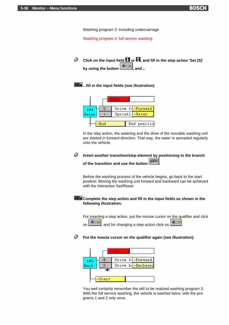
Monitor – Menu functions5-38
Washing program 2: including undercarriage
Washing program 3: full service washing
Click on the input field or , and fill in the step action ‘Set (S)'
by using the button , and...
...fill in the input fields (see illustration)
In the step action, the watering and the drive of the movable washing unitare started in forward direction. That way, the water is spreaded regularlyonto the vehicle.
Insert another transition/step element by positioning to the branch
of the transition and use the button .
Before the washing process of the vehicle begins, go back to the startposition. Moving the washing unit forward and backward can be achievedwith the interaction Set/Reset:
Complete the step action and fill in the input fields as shown in thefollowing illustration:
For inserting a step action, put the mouse cursor on the qualifier and click
on , and for changing a step action click on .
Put the mouse cursor on the qualifier again (see illustration).
You well certainly remember the still to be realized washing program 3.With the full service washing, the vehicle is washed twice; with the pro-grams 1 and 2 only once.

Monitor – Menu functions 5-39
In this case, the programming of a loop is useful. The washing process isexecuted within the loop. Only with the washing program 3, the loop isexecuted twice. The loop repetitions have to be counted. That is why weneed a counter (index variable), which has to be put before the entry intothe loop:
Click on the button ‘Insert step action’ and choose the stepaction ‘Set counter (SC)’.
Fill in the input fields ‘Counter’ and ‘Value’ (see illustration).
Insert another new step element
Fill in Wash to the comment field of this step 1N6 (see illustrationbelow).
This step element - and another - shall regulate the washing processwithin the loop. The loop shall be led around the element which has justbeen inserted.
Mark the area where the loop has to be led around. This process isshown to you via a short video demonstration, if you click on this button
For the marking, put the mouse cursor a little bit above the step1N6.
The mouse cursor changes its shape

Monitor – Menu functions5-40
Click again on this position and keep holding the left mouse button.Move the mouse in the direction of step 1N6. Now, a small rectangleis drawn. As soon as you touch the step, the whole step element isillustrated inversely. Please release the mouse button.
You have marked the step element (transition/step). Marked elementscan be deleted (button ), copied (copy + insert) or moved (cut + in-sert). However, you can also put a branch or a loop around the marking.In other words: Marked objects are integrated into the branch or the loop.
Click on the button ‘Loop’
As desired, a loop is put around the marked element. Furthermore, abovethis element, another step element is produced before the line with an ar-row.
Complete the step actions in step 1N6 and 1N7, and fill in all inputfields as shown in the following illustration.
Put the mouse cursor on the branch of the transition below the loop

Monitor – Menu functions 5-41
What happens in the loop?In the step action immediately before the loop (step 1N5), the counterC_Wash is put on the value two. Step 1N6 starts the washing process (-Brush). How the brushes in the carwash are driven, shall not be specifiedfurther. The counter is decreased by one value via the step action ‘Dec-rement counter (CD)’. Hence, the counter equals one. The movable unitis moved forward and in step 1N7, it is moved backward. Next up is thecheck of the transition below the loop (which is edited at a later date).The check of the return condition causes a jump (to the top end of theline with the arrow) in the washing program 3, so that the washing proc-ess is executed once again. Also, the washing unit has to be at the startposition. In the next cycle, the counter is set to the value zero.
Next, the condition of the counter has to be evaluated.
5.12.9 Cyclical execution of the sequence
Before you start with the input of the transition condition below the loop,insert the final step elements. In our example, there are still three transi-tion/step combinations necessary:
Click on the button ‘Transition/Step combination’ three times
Complete now the transition conditions for the exit out of the loop(see illustration).
You can achieve the connection of the transition with the positioning tothe entry or the branch in front of the transition and with the execution of
or . Likewise at this positions, the conditions are negated
.
We are now nearing the completion of our program example. The laststeps rinse off and dry the vehicle. Besides, the brush drive of the wash-ing process is still active. It is set back as follows:
Complete the step actions and fill in the input fields, as shown in thefollowing illustration.

Monitor – Menu functions5-42
The vehicle is now washed and can be driven out of the carwash:
Here too, we would like to ask you to complete the inputs:
After moving the vehicle out of the carwash (transition to End), the exe-cution of the sequence starts all over again (Start).
Click on the button to save the SFC-File
So, that´s it for now concerning the editing in the SFC. Now it goes onwith creating and loading the sequence.
5.12.10 Create and load
Before loading the SFC file, the sequence has to be created. With thecreation, the sequences are changed to IL instructions and edited intoprogram modules. Different symbols of the sequence are edited to thesymbol file.
There are two ways of creating a sequence:
1 Via the menu function ‘File’, ‘Create sequence’
2 With the loading via activating the control field ‘Create sequence’ inthe load dialog box.

Monitor – Menu functions 5-43
Please decide on one of the two possibilities. If you want to load into thecontroller, then do not forget to make the connection between PC andPLC .
Do not load the programming example into an active system!
As already mentioned, different modules are produced with the creation.However, the module KETTE.PXL (KETTE200.PXL for CL200,KETTE700.PXL for CL700) which does the cascade organization, is notproduced. This file is available as a disk with the MADAP software pack-age, which you can order through the Bosch software service. Copy thismodule to the library or ZS directory.
If you make the creation in the load dialog box, then click on the button‘Options’.
Activate the field ‘Create cascade call in OM1’ in the dialog box andstart the creation via the button ‘Create’ or ‘OK’, respectively.
The information that all changes in the OM1 are getting lost, appears.Because OM1 has not yet been edited, this does not really matter. Con-firm the message with ‘Yes’.
Now, the dialog box ‘Cascade/Step parameter’ appears. Here, you haveto set the MADAP time parameters Waiting (KWA) and Watchdog timer(KUE) (with the controller CL200, some additional parameter have to beedited):
Put the value 30 to the field KWA and the value 40 to the field KUE.
All inputs are now finally done. The creation is now executed. The creat-ing process is recorded in a dialog box. If an error occurs (e.g. if youhave made wrong inputs), a message appears which lists the positionand the cause of the error. In this case, you have to eliminate the errors.
If the creation runs without an error, the following message appears:Project has successfully been created.
5.12.11 The SFC Monitor
As with the other programming languages, a SFC program can also betested with the monitor. When you have loaded the program to the con-troller, you can immediately change to the monitor.
Please remember that you have made a (simplified) program for a car-wash. To follow the sequence in the monitor, the corresponding sensorsand actuators ought to be connected with the controller. Because this isnot the case, we have prepared a special simulation program. It appearsat first as a SFC file WASHINCH.AS in the program directory on yourharddisk. If you want to execute the simulation in the monitor, then copythe file to the current ZS directory and create and load the SFC with thisfile. To start running the sequence in the controller, the mode selectionhas to be realized in MADAP. If you actuate this button , you can seean example for the mode selection for the simulation program.

Monitor – Menu functions5-44
Click on the monitor button
On the sequence level, the current condition of the sequence is indicated.Active steps and fulfilled conditions are represented in red. If all condi-tions (transition or command output) are fulfilled in a complex transition orBEFA, the red line is drawn continuously up to the branch of the transi-tion or BEFA condition (see illustration). A negated condition is repre-sented in red when the negated condition is submitted.
With the menu function ‘View’, ‘Show timer and counter values’, theWaiting (KWA) and Watchdog timer (KUE) is appended to every step.Furthermore, the current values are distributed at the timer and counterstep actions.
Activate the function ‘Synchronize to cascade number’:
Click on the button . Activate the control field ‘Follow cascade’in the dialog box and confirm with ‘OK’.
Now, the monitor display is always put to the position of the active step.Thus, you can follow the sequence.
In the simulation of the program, the condition of the Waiting time (KWA)is checked in every transition. When the Waiting time (3 seconds in ourexample) is over, the transition will be done. You can see the simulationof the washing program 3.
This is the sequential function chart introduction so far. You can get addi-tional support for the WinSPS programming via the online help.
You will find detailed general information about the SFC in theReadSFC.doc file which is contained in the WinSPS program directory.

Monitor – Menu functions 5-45
5.13 Instruction List as per IEC 61131-3 (IEC IL)
Please observe the special Presets for the programming according toIEC 61131-3:
In order to avoid any confusion, the following terms are used:IEC IL: Instruction list as per IEC 61131-3.Bosch IL: Classic instruction list (based on DIN 19239).
The following program examples cover the programming in IEC IL. Pro-gram examples for the Bosch IL can be found at an earlier point in thissection.
The structure of programs according to IEC 61131-3 as well as the inputoptions in the WinSPS Editor are identical for all programming languagesaccording to IEC 61131-3. Different inputs are only made in the declara-tion part of the Editor, depending on the specific programming language.For this reason, this section will only describe different examples for in-structions in the IL programming language. The input of variables in thedeclaration tables as well as the generation of a loadable project areexplained in the section about the ST (Structured Text) programminglanguage.
In IL, execution instructions for the PLC are specified in one line. A com-plete sequence of instructions (IL sequence) can extend over multiple in-struction lines.
An IL instruction line is defined by the following format:

Monitor – Menu functions5-46
Please observe this input format. It is particularly important that at leastone space character or tab character is entered between theoperator and the operand.
Further information about IL instructions:
5.13.1 Boolean operations
The sequence of execution in IL is always top down. The first instructionline of an IL sequence (in Bosch IL: program branch) is always a load in-struction "LD" or "LDN". The IL sequence is terminated with an assign-ment, e.g. “ST” (Store). Here is a program example:
LD x20AND x21OR x22AND x23ANDN x24ST led0
Different Boolean (logical) operators are used. They have the followingmeaning:
Operator Boolean Meaning
AND Boolean AND
OR Boolean OR
ANDN Boolean AND, negated

Monitor – Menu functions 5-47
Overview of the IL instruction set:
The result is assigned to the variable "led0" by means of the assignmentoperator “ST”.
The program example corresponds to the following Boolean equation:
This corresponds to the following representation in the programming language Function Block Diagram(FBD):
...and the Ladder Diagram (LD) would look like this:
TIP
You may also use the short form “&” (commercial And) for the Booleanoperator “AND”. The above programming example could be entered asfollows:
LD x20& x21OR x22AND x23&N x24ST led0

Monitor – Menu functions5-48
5.13.2 Boolean operations – Parentheses
In the above example, the Boolean operations were still quite simple.However, it is often required to calculate (combine) partial expressions inorder to combine the result obtained here with other operands. Such par-tial expressions can be entered in parenthesis operators “( )”.
Detailed information about parenthesis:
The following Boolean equation is a logical combination in which – con-trolled by the arrangement of the parentheses – all AND operations " "are executed before the OR operations " ":
This equation corresponds to the following FBD representation:
The last parentheses around the operand "x23" is not necessary becausesingle operands are not placed in parentheses. For this reason, the pa-rentheses are also left out in case of conversion to IL.
Each IL sequence must always start with a load operation "LD" or "LDN".However, a load instruction must not be used to open an nesting level.For our example, this means that the first nesting level is not possible –but also not necessary, due to the sequence of execution. The equationcan be simplified:
Sequence of execution
In IL, this equation is entered as followed:

Monitor – Menu functions 5-49
LD x20ANDN x21AND x22OR( x20AND x24)OR x23ST led1
To introduce a nesting level, the parenthesis is placed directly after theoperator, e.g. "OR(". Each nesting level is terminated in a separate in-struction line with the closing parenthesis “)”. The introduction of nestinglevels is only possible with certain operators.List of operators:
Representation of the example in the programming language LD:
5.13.3 Boolean operations – Nested parentheses
Expressions in parentheses “( )” can be nested in several levels.
Example 1, FBD:

Monitor – Menu functions5-50
Ladder Diagram:
Boolean equation:
Instruction List:
LD x20AND x21AND( x22AND x23OR( x22AND x24)OR x00)AND x26AND( x27OR( x20ANDN x01))ST led2
The example can be simplified. The two AND operations at the beginningof the equation (X20, x21) can be moved to the position of the vari-able”x26”. This will shift one nesting level:
LD x22AND x23OR( x22AND x24)

Monitor – Menu functions 5-51
OR x00AND( x20AND x21AND x26AND( x27OR( x20ANDN x01)))ST led2
Example 2, FBD:
Ladder Diagram:
Boolean equation:
Instruction List:
LD x20AND x21

Monitor – Menu functions5-52
AND x00OR( x22AND x21)AND( x23OR( x20AND x24))AND x25ST led3
Detailed information about parentheses:
5.13.4 Loading a program and more program examples
You can find additional input examples for the programming in IL in thesections about the IL operators in the chapter “Programming”. This is aselection:
Load instructions
Assignments
Boolean (logical) operators
Arithmetic operators
Comparison operators
Jump operators
Call of function blocks
Call of functions
Return operators
Loading a program into the controllerBefore the program can be loaded into the controller, the project must begenerated. Information about this is contained in the section "Generateand load project” of the ST programming language:

Monitor – Menu functions 5-53
Testing a programYou can test a program according to IEC 61131-3 by means of theMonitor.

Monitor – Menu functions5-54
5.14 Compact and clear: Structured Text (ST)
The WinSPS software offers you two variants of ST programming:
1) Combination of an ST program with conventional programming
2) ST program without conventional elements
The first variant is especially useful if you want to program certain func-tions in ST while programming other control functions e.g. conventionalIL. In this case, the ST modules are called up by the IL but not vice versa,e.g.
CM -AmountWith the second variant, however, only ST instructions can be used. Thisis useful if no programming languages other than ST are to be used in acontrol program.
The different module structure of the two variants is exemplified in thefollowing illustrations:
Combination of IL and ST
ST without conventional program elements

Monitor – Menu functions 5-55
Please decide by yourself which variant to choose. Our sample programrepresents the first variant. Since using the second variant is only slightlydifferent, we will point out these differences in the appropriate places.This will enable you to implement both variants of our sample program.
Before you start making entries in the ST Editor, we want to explain oursample program a bit:The task is to count and add coins of 10 Pf., 50 Pf., 1 DM, 2 DM and 5DM. Then the total amount is to be given in DM and EURO, e. g. für diedisplay elements of a coin counting machine.
You are in the WinSPS Editor. If you have not yet selected the program-ming language Structured Text, please do this now:
Click on the ‘ST’ button.
5.14.1 Declaring variables
The ST Editor is subdivided into different areas.

Monitor – Menu functions5-56
If the declaration tables are not visible, click on the button.
For the “AMOUNT” module, select the POU type FUNCTION_BLOCK:
Click on the variable declaration.
You will see a table in which the local variables are edited.
Click on the first table field below “Variable type”.
A selection button will appear
Click on the button and select the variable type “ VAR_INPUT”.
Enter a variable name:
Double-click on the first table field below “Name” and ...
... enter the name PF_10 in this field.

Monitor – Menu functions 5-57
Following this procedure, please fill in the next two fields “Data type” and“Initial value”, as shown in the following illustration:
This concludes the definition (declaration) of the first input variable. Thisis an integer (INT) variable with the name PF_10 and an initial value of 0.In addition, this is purely an input variable (VAR_INPUT). These impor-tant properties of a variable are defined by the international standard IEC61131-3.
If you need further information about these properties or about the layoutand use of the declaration tables, please consult the following help func-tion:
The declaration tables allow a very convenient entry of variables whileproviding a very good protection against incorrect entries. You can alsoedit the variables directly in the ST file. Switch off the declaration tablesin order to edit within the text-only representation.
Click on the button.
The declaration tables are now hidden. Instead, you see the module typeand name, as well as the declaration part of the current module:
FUNCTION_BLOCK AMOUNT
VAR_INPUT PF_10 : INT := 0;END_VAR
Please declare other variables which are required for the sample pro-gram. In doing this, you may choose whether to make the entries directlyin the text or in the declaration tables. The illustrations below show bothoptions.
Remember the two ST programming variants: with or without conven-tional program elements. We want to point out a difference here. If youwant to implement the program without a call from the conventional IL,please disregard the variables below and click on this button instead:
Text programming:
FUNCTION_BLOCK AMOUNT
VAR_INPUT PF_10 : INT := 0; PF_50 : INT := 0; DM_01 : INT := 0; DM_02 : INT := 0; DM_05 : INT := 0;END_VAR

Monitor – Menu functions5-58
VAR_OUTPUT Amount_in_DM : REAL := 0.0; Amount_in_Euro : REAL := 0.0;END_VAR
Declaration tables:
With the declaration, all relevant variables of the module are declared.Now the program instructions can be entered.
5.14.2 Instructions
Instructions are entered in the instruction part. If you have disabled thedeclaration tables and want to make your entries in text-only program-ming mode, please observe that the instructions need to be enteredabove END_FUNCTION_BLOCK.
Enter the following instructions:
Amount_in_DM := (int_to_real(Calculate (PF_10, PF_50, DM_01, DM_02, DM_05)) /100.0);Amount_in_Euro := Amount_in_DM / 1.95583;
The first instruction calls up the “Calculate” function. This function is usedto count the coins and is still to be defined (see below). The bracketscontain the parameters which are passed to the function, PF_10, PF_50,etc. The result of the function is used to convert from “Pfennig” into “DM”(German Deutsche Mark). Since the result of the Calculate function andthe variable “Amount_in_DM” are not of the same type – Calculate = INT,Amount_in_DM = REAL –, the type conversion “int_to_real” is required.
The last instruction is finally used to convert the DM amount into EURO.
You will find further information in the following sections of the WinSPShelp:
ST programming language
Programming according to IEC 61131-3
As mentioned above, the Calculate function needs to be defined. For thispurpose, create a new ST file:

Monitor – Menu functions 5-59
In the ‘File’ menu, click on the option ‘New/Open’, or...
... press the key combination + + .
A dialog box will appear. Enter the file name Calc and confirm your entrywith .
The variable declaration and the instructions in this module shall look asfollows:
FUNCTION Calculate : INT
VAR_INPUT PF_10 : INT; PF_50 : INT; DM_01 : INT; DM_02 : INT; DM_05 : INT;END_VAR
VAR Total : INT := 0;END_VAR
Total := Total + PF_10 * 10; Total := Total + PF_50 * 50; Total := Total + DM_01 * 100; Total := Total + DM_02 * 200; Total := Total + DM_05 * 500;
Calculate := Total;
END_FUNCTION
If you do not want to enter these instructions by hand, you can also copythe texts directly from the help text into the ST Editor. To do so, highlightthe above instructions and select the function ‘Edit’, ‘Copy’ or the keycombination + . Within the ST Editor, you can then place thecopied text in the desired position with ‘Edit’, ‘Insert’. However, a com-ment line will be appended:
„WinSPS Help ... Copyright © ... Robert Bosch GmbH“
You will need to delete this line!
Meaning of the instructions:In the declaration part, all input variables of this function are declared.The internal integer variable “Total” is used to form the subtotal.

Monitor – Menu functions5-60
Since the input variables contain the respective number of coins, thisnumber is multiplied with the corresponding monetary value in the decla-ration part. The result is added to the total with each calculation of theamount. The last instruction assigns the total to the function name. Thisis mandatory for functions.
5.14.3 Modules and module calls
Please enable the declaration tables if this are not already enabled.
Please switch to the display of the “POU type“.
If you have entered the instructions as shown, you will see that a POU ofthe type “FUNCTION“ is used here. This type of module is suitable formaking calculations. The result of a calculation is returned to the callingmodule so that this result can be used in further calculations.
This fact is also utilized in our sample program. The return variable of theCalculate function is used in the “Amount” module to make a direct cal-culation of the DM amount, see extract from “Amount”:
Amount_in_DM := (int_to_real(Calculate (PF_10, PF_50, DM_01, DM_02, DM_05)) /100.0);
The two modules “Amount” and “Calc” shall be sufficient for our simplesample program. In the next step, we will use these modules to create aloadable program.
Please save the files, which can be done most conveniently by using the“Save all” function:
Click on the button or...
...press the key combination + + .
5.14.4 Project preparations
Switch into the symbol file:

Monitor – Menu functions 5-61
Click on the Symbol Editor button or...
...press the key combination + + .
The symbol file already contains some essential entries. The followingline should be there:
OM1,R OM1 ; Cyclic program execution
Still remember the two program variants?
1) Combination of an ST program with conventional programming
2) ST program without conventional elements
Only if you select the second variant, you will need to change the entry inthe symbol file:
OM1,R AMOUNT ; Cyclic program execution
As you can see, the ST module “Amount” is directly entered into thesymbol file in the position of the OM1. This is important for the controlprogram since this always starts with the OM1!
Please save the symbol file, e.g. using the “Save all” function”:
Click on the button or...
...press the key combination + + .
This concludes the most important preparations to create an ST project.This procedure is terminated with the “Create project” function.
But let us consider one more thing first. In the symbol file, we have cre-ated a link to our ST program via the entry OM1, R AMOUNT. However,we have only done this for the second programming variant. But whatabout programming with conventional elements? Obviously, a link to theST modules has not yet been created. Below, we will show you how thislink is created.

Monitor – Menu functions5-62
Variant 1: Call in IL
Variant 2: Call only in ST
If you have generally adopted the second programming variant, you mayskip the next paragraph. To do this, click on this button:
5.14.5 Module call in conventional programming
The ST module “Amount” is to be called up from an IL module. For thispurpose, we will use the organization module OM1 which represents thelowest level of conventional programing.
Please change into the IL Editor and edit the OM1 module:
Click on the module edutor button and...
...Click on the IL button .

Monitor – Menu functions 5-63
If you have entered the proposed filenames during the preparation, youcan now edit the OM1. Otherwise you will need to enter OM1 in the edit-ing field for the filename:
Place the insertion mark after the comment lines but before the in-struction ‘EM’.
In order to be able to call a module from the conventional environment,this module must be a FUNCTION_BLOCK. In our case, only the FB“Amount” is available.
Press the key combination + or...
... In the “Edit” menu, click on the ‘Call parameter list’ menu option.
A dialog box will open in which you can select a module. All functionblock modules (FB, FUNCTION_BLOCK) are listed. Since only one FBmodule has been created in our example, only this one will be displayed:
Confirm the selection of the AMOUNT module by clicking on the‘Continue’ button.
In the next dialog box, instances are selected. What are instances ?In our example, we have created a function block with the name“Amount”. More precisely, however, this is only a type name. Now, wehave a FB module of the type “Amount”. The actual name is definedthrough the instance. This instantiation – or formation of instances – isvery similar to the declaration of variables. Please have a look at the fol-lowing example:
VAR_GLOBAL Coin_counter1 : AMOUNT; Coin_counter2 : AMOUNT;END_VAR

Monitor – Menu functions5-64
This variable declaration is used to exemplify that e. g. two different vari-ables – or, more precisely: two different instances – of the type AMOUNTcan be declared. These two instances use the same FM but can becalled and evaluated in different places. This means that there are alsotwo separate data areas. In this way, you can e.g. cleanly access severalamounts from different coin counters without these affecting each other.
This mechanism is used to create modules “with a memory”. The FBmodules (FUNCTION_BLOCK) are such modules. On the contrary, func-tions (FUNCTION) are “without a memory”. This is the reason why func-tions such as “Calculate” in our example are not displayed in the firstplace for the purpose of module selection and instantiation.
But now – back to the dialog box for instance selection. Enter an instancename:
Confirm your entry by clicking on the ‘Continue’ button.
Another dialog box will appear where you can initialize the variables us-ing actual parameters. Double-click on the respective table element un-der “Actual parameter” and enter the following initial values:
Terminate your entry by clicking on the ‘Execute’ button.
WinSPS will create different entries in the IL Editor and – not visible here– in the symbol file. Please do not change these lines – especially notthe comment lines!
Please save the file, e.g. using the “Save all” function”:
Click on the button or...

Monitor – Menu functions 5-65
...Press the key combination + + .
This concludes the integration of the ST module call into the IL and cre-ates a consistent link between the symbol file and all IL and ST modulesof the program.
The following steps apply again to both programming variants.
5.14.6 Creating and loading
Now we need to create the project. The creation process will compile allST modules (= convert them into control instructions), check all modulecalls and finally create an executable control program from all modules.This process will also automatically create various data modules for theinstantiation of the function block modules. Do not change the entries inthe data modules!
In the ‘File’ menu, click on the menu option ‘Create new project’.
The creation is then started, and the creation process is logged in a dia-log box. If an error is detected (e. g. due to incorrent entries), a messagelists the position and cause of the error. In this case you will need to cor-rect the errors.
In addition, compilation errors are displayed in the error window. For fur-ther information, refer to this Help section:
If the creation executes error-free, the message: ‘Project created suc-cessfully’ will appear.
If you want to load the program into the controller, please do not forget toestablish the connection between the PC and the PLC.
Do not load the programming example into an active system!
5.14.7 The ST Monitor
As with all other programming languages, an ST program can be testedby means of the Monitor. After loading the program into the controller,you may change directly into the Monitor.
It would not make much sense to load our simple sample program be-cause, after all, this program does not provide any results. We want toshow you which data are displayed in the ST Monitor in the case of a“useful” program. It should be mentioned that the Monitor allows you toselect the instance of the respective module you want to monitor.

Monitor – Menu functions5-66
The current data are displayed in the “Monitor data” column of the vari-able declaration.
This concludes the explanations about ST progarmming. You can getadditional assistance for programming in the WinSPS on-line Help.

Programming 6-1
6 ProgrammingIn the WinSPS software, programming is possible in two different ways:
1) Classic programming2) IEC 61131-3 programming
Classic programming includes those programming languages that arebased on the DIN 19239 standard and VDI directive 2880. Since the in-troduction of Programmable Logic Controllers from Bosch, this classicprogramming is used for IL, LD and FBD and has continuously been en-hanced to meet the current technical requirements.
Based on the experiences with the classic PLC languages, new pro-gramming languages and an associated data concept were standard-ardized internationally by the IEC 61131-3 (DIN EN 61131-3) standard.The WinSPS currently supports the programming in compliance with IEC61131-3 with the programming languages Sequential Function Chart(SFC) and Structured Text (ST).
Detailed information about the standard compliance of the programminglanguage according to IEC 61131-3 are found in the chapter “IEC 61131-3 standard compliance”:
In addition, there are many places in classic programming where theWinSPS allows to use the terminology of the IEC 61131-3 standard in or-der to achieve a partial compatibility.
A complete overview of the differences between these two programmingmodes is also contained in this chapter:
The language elements of both programming modes are described be-low. The description of classic programming is based on the IEC 61131-3standard and pinpoints restrictions and enhancements.
6.1 Classic programming – Language elements, variables, data types
6.1.1 Character set
Encoding of the character conforms to the (8-bit) Windows-ANSI char-acter set.
DesignatorA designator is a sequence of characters, digits and underscores (_) thatmust start with a letter or an underscore. Underscores are significant.Multiple underscores (__) are not permitted. A designator can contain upto 32 characters. As an extension of IEC 61131-3, uppercase and lower-case letters within designators are significant. "Umlaute" - such as ä, ö, ü,ß - within designators are not permitted. Here are some examples:
Correct: Incorrect:VOLTAGE_REGULATOR VOLTAGE__REGULATOR_Rotation_plus _rotation_+Marker_2 2_Marker

Programming6-2
By activating the function switch. /O2, a checking process is turned off sothat more than one underscore in the symbol naming is permitted. Theunderscore in the names is significant, e.g. AB_C is not the same asA_BC.
KeywordsKeywords (A, O, BYTE ...) must not be used for other purposes, e. g.they are not permitted as variable names.
Use of blanksOutside of keywords, literals and designators, it is possible to use one orseveral blanks or tabs.
Example:
A W I3 (* Comment *)
CommentsComments must be enclosed in a special character combination (* and*). Nested comments are not permitted. Any characters from the ANSIcharacter set can be used within comments. As an extension of IEC1131-3, comments may also be separated by a semicolon.
Example:
(* IEC-compatible comment notation *)
; permitted comment notation
6.1.2 Numeric literals
A numeric integer literal is defined as a decimal number or a number re-lated to a base. Underscores which are inserted to enhance the readabil-ity are allowed and are not significant. Leading underscores are notpermitted.
Decimal literals are represented in the usual decimal notation. They maybe preceded by a sign ( + or - ). Base-related number must not have asign. The letters A through F for the hexadecimal numbers 10 through 15may be lowercase or uppercase.
Floating point numbers can be written with a decimal point “.” or in expo-nential representation. They can also be signed.
Logic data are represented by the keywords FALSE and TRUE.
Examples for numeric literals:
Characteristic: Examples:Logic data TRUE (not equal to 0)
FALSE (0)Integer literals -12
0123_456+986
Base-2 literals 2#11111111 (255 decimal)2#11100000 (240 decimal)

Programming 6-3
Characteristic: Examples:2#1111_1111_1111_1111 (65535 decimal)
Base-8 literals 8#377 (255 decimal)8#340 (240 decimal)
Base-16 literals 16#FF or 16#ff (255 decimal)16#1000 (4096 decimal)
Floating point +523.31-0.08398E+4 (Exponent)4e2-34E-15
6.1.3 String literals
A string literal (formerly ASCII constant) is a sequence of zero or morecharacters which is enclosed in single quotation marks (‘). In strings, thecombination of the dollar sign ($) followed by two hexadecimal digits isinterpreted as the hexadecimal representation of the 8-bit character code.In addition, character combinations with a leading dollar sign are inter-preted as shown in the table below:
Character combination Meaning$$ single dollar sign$’ single quotation mark$L or $l Line Feed (LF)$P or $p Form Feed (FF)$R or $r Carriage Return (CR)$T or $t Tab stop
Examples for string literals:
Characteristics: Examples:‘’ Empty string‘ ’ String of length one, with blank‘$’’ String of length one, with single quotation mark‘$R$L$0D$0A’ String of length 4, with 2 CR and LF characters each‘$$1.00’ String of length 5 which is printed as “$1.00“
Please also observe the following properties:
6.1.4 Timer literals
Of the possible timer literals according to IEC 61131-3, the current ver-sion of the WinSPS software supports the duration type. Data for the du-ration need to be introduced by the keyword T# or t#. Only seconds (s)and milliseconds (ms) are permitted as units for duration literals. Durationliterals cannot be separated by underscores.
As an extension to IEC 61131-3, the internal timer specifications via timervalue (x = 0 through 999) and timer loop (y = 0 through 3) are still possi-ble (T#x.y).
Examples for timer literals:
T#14ms
T#23.3

Programming6-4
6.1.5 Data types
The table below lists all data types according to IEC 61131-3 which aresupported by the classic programming mode.
Keyword: DataWidth(Bit):
Default: Explanation:
BOOL 1 0 Truth value (not equal to 0 => TRUE, equal to 0 => FALSE).BYTE 8 0 Bit sequence of length 8 (0 through 255).WORD 16 0 Bit sequence of length 16 (0 through 65535).DWORD 32 0 Bit sequence of length 32 (0 through 4.294.967.295).SINT 8 0 Short integer, signed decimal (-128 through +127).INT 16 0 Integer, signed decimal (-32768 through +32767).DINT 32 0 Double integer, signed decimal (-2.147.483.648 through
+2.147.483.647).USINT 8 0 Unsigned short integer, unsigned number with selectable base in the
value field (default: decimal).UINT 16 0 Unsigned integer, unsigned number with selectable base in the value
field (default: decimal).UDINT 32 0 Unsigned double integer, unsigned number with selectable base in
the value field (default: decimal).STRING(x) var. $00 ASCII string of length x. Representation: Hexadecimal 20 through 7F;
characters above 7F with leading $ character (e.g. $80). The string isenclosed in quotation marks (e. g. ‘Test’). It is also possible to enterspecial control characters.
OSTRING(x) var. $00 Octet string of length x. Representation: 2 hexadecimal digital percharacter (00 through FF).
VSTRING(x) var. $00 Visible string of length x. Representation: hexadecimal 20 through 7Fas US-ASCII characters. Any other characters are not permitted. Thestring ends with a non-ASCII character (e. g. TAB).
ISTRING var. „127.0.0.1“ TCP/IP Address (e. g. for COM-E modules)Format: “xxx.xxx.xxx.xxx“
TVALUE 16 0s Timer. Input in seconds (s), milliseconds (ms) or as a timer value/loop.The input value in s and ms is automatically rounded according to thetimer value/loop.
CVALUE 16 0 Counter. Permitted range 0 through 8191.REAL 32 0.0 Floating point (Double word)
(1.175494351e-38 through 3.402823466e+38)LREAL 64 0.0 Floating point (Quad word)
(2.2250738585072014e-308 through 1.7976931348623158e+308)
Of the possible IEC 61131-3 data types, only the elementary data type isavailable. Classic programming does not support the processing of ge-neric and derived data types as well as of the 64-bit data types LINT,ULINT, LWORD.
6.1.6 Variables
Variables are data that are associated with inputs, outputs or a memoryaddress of the PLC.
The symbolic representation of variables is made with designators as de-fined in the “Character set“ section. Symbolic designators are precededby a hyphen (-).

Programming 6-5
Bit memory locationsA direct representation of a bit variable (as an absolute operand) is de-scribed by a prefix for the memory location and one or more unsignedintegers that are separated by a dot (.). The notation according to IEC61131-3 that uses a leading per cent sign (%) is replaced with a shorternotation (e. g. I0.0).
Byte/Word/double-word memory locations
A direct representation of a byte/word or double-word variable (as an ab-solute operand) is described by a prefix for the memory location and oneor more unsigned integers. Operands are always counted in decimal bytesizes. For this reason, 16-bit operands can only be used on even ad-dresses, and 32-bit operands only on addresses which can be divided by4. The former address counting (e. g. I4W) is discontinued. For this rea-son, the designation I8 will always be
input byte 8 for byte addressing,
input byte 8/9 for word addressing, and
input byte 8/9/10/11 for double-word addressing.
The notation according to IEC 1131-3 that uses a leading per cent sign(%) is replaced with a shorter notation.
As an extension to IEC 1131-3, the addresses of some memory locationscan be derived from the address operator (&) that is used as a prefix.
Examples:L &M0.0,A ; Load the address of marker M0.0 into accu A
The table below contains all prefixes for accesses to memory locations:
Prefix: Meaning:M Memory location: MarkerSM * Memory location: Special MarkerS * Memory location: System rangeT * Memory location: TimerP * Memory location: ParameterFC Non-remanent function call (formerly: PM)D * Memory location: Data in first data moduleDX * Memory location: Data in second data moduleDF * Memory location: data fieldTI * Timer interrupt registerPI * Peripheral interrupt registerSI * System interrupt registerCY * Carry FlagZ * Zero FlagN * Negative FlagO * Overflow FlagI Memory location: InputQ Memory location: OutputOM * Organizational moduleDM * Data module

Programming6-6
C * Memory location: CounterII * Memory location: Interface InputIQ * Memory location: Interface OutputEI * Memory location: Extended InputEQ * Memory location: Extended OutputC * Memory location: CounterDB * Memory location: Data buffer
Prefixes marked with * are extensions to IEC 1131-3.
The table below contains all prefixes for the data width (operand attrib-ute):
Prefix: Meaning:X Bit sizeB Byte (8 bits)W Word (16 bits)D Double-word (32 bits)R Real (32 bits)L Long Real (64 bits)
The bit attribute (X) is the default and can be omitted.
The possible combinations of the “Memory Location” and “DataWidth” prefix tables as well as the address depend on the control-ler.
6.2 IEC 61131-3 – Program Organization Unit (POU)
6.2.1 Module types
In the terminology of IEC 61131-3, program modules are so-called Pro-gram Organization Units, in short: POU. There are three types of POUswith different characteristics:
Program block (Keyword: PROGRAM, short: PROG)
- Main program including the assignment of PLC peripherals, globalvariables and access paths.
- Can call up function blocks and functions.
- In mixed programmig using ST and e. g. classic IL, a PROGRAMPOU must not exist. In this case, the main program is implementedthrough the OM1.
Function block (Keyword: FUNCTION_BLOCK, short: FB)
- Can have none, on or multiple input parameters.
- Can have none, one or multiple output parameters.
- Multiple instances of a function block can be created; these have in-dependent storage areas for inputs, outputs and intermediate results.
- Has a 'memory', i. e. the local variables of the block retain their (in-stance-specific) value through multiple calls.

Programming 6-7
- It is not the function block itself that is called but always an instance ofa function block.
- In a call, it is not necessary to specify all input parameter; any missinginput parameters will retain their values from the previous call or arepreset with defaults.
- Can call up functions and instances of other function blocks.
Function (Keyword: FUNCTION, short: FUN)
- Can have none, one or multiple input parameters.
- Returns exactly one return value.
- Has no 'memory', i. e. it will deliver identical results for identical inputvalues.
- In every call of the function, it is necessary to specify all input pa-rameters.
- Can use local variables for intermediate results; however, these willnot retain their values through multiple calls.
- Can call up other functions but not function blocks.
The partitioning into modules achieves a modularization of the automa-tion task and allows the reuse of predefined and tested software compo-nents.
6.2.2 Program block (PROGRAM)
The program block PROGRAM is the main program of a PLC. In thisPOU, the PLC starts the program execution and calls up the subpro-grams (functions and function blocks).
The program block must be entered in the symbol file as OM1.
Examply entry in the symbol file:
OM1,R HELLO_ST ; Cyclic program execution
In mixed programming including ST and e. g. classic IL, a PRO-GRAM POU must not exist. In this case, the main program is imple-mented through the OM1.
The program block has special properties:
- This is the only place where directly represented variables, i. e. physicalPLC addresses: %I, %Q, %M can be declared.
- VAR_GLOBAL can be used, so that access to this data is possible insubprograms through VAR_EXTERNAL.
- It is called up by the operating system of the PLC, i. e. the main pro-gram must never be called up from functions or function blocks.
- It starts with the keyword PROGRAM and ends with END_PROGRAM.

Programming6-8
Example of a small ST-Program:
PROGRAM HELLO_ST (* Start and name of POU *)VAR (* Declaration section *) OUTPUT AT %Q0.0 : BOOL; INPUT AT %I0.0 : BOOL; Enable_signal : BOOL;END_VAR IF INPUT=TRUE THEN (* Instruction section *) Enable_signal:=TRUE ELSE OUTPUT:=0; END_IFEND_PROGRAM (* End of program *)
6.2.3 Function block (FUNCTION_BLOCK)
Function blocks are parametrizable POU with static variables (with‘memory’). They are the key tool to structure PLC programs.
Multiple instances of a function block can be created; these have inde-pendent storage areas for inputs, outputs and intermediate results.
They are called up by programs or other function blocks and can them-selves call up functions and function blocks.
Example of an ST function block:
FUNCTION_BLOCK AMOUNT
VAR_INPUT PF_10 : INT := 0; PF_50 : INT := 0; DM_01 : INT := 0; DM_02 : INT := 0; DM_05 : INT := 0;END_VAR
VAR_OUTPUT Amount_in_DM : REAL := 0.0; Amount_in_Euro : REAL := 0.0;END_VAR
Amount_in_DM := (int_to_real(Calculate (PF_10, PF_50, DM_01, DM_02, DM_05)) /100.0);
Amount_in_Euro := Amount_in_DM / 1.95583;
END_FUNCTION_BLOCK

Programming 6-9
6.2.4 Function (FUNCTION)
Functions have input parameters but no output parameters. Functionsreturn exactly one element as a return value. The function name itself isused as an internal variable to assign the return value.
Internal variables are not static, i. e. they have no ‘memory’. With identi-cal input values. a function will always return an identical return value,regardless of when and how often the function is called up. This is whylocal variables must not be declared as buffered.
Global variables must not be used.
Function blocks (FUNCTION_BLOCK) must not be called up within thefunction. However, other functions may be called up.
Example of an ST function:
FUNCTION Calculate : INT
VAR_INPUT PF_10 : INT; PF_50 : INT; DM_01 : INT; DM_02 : INT; DM_05 : INT;END_VAR
VAR Total : INT := 0;END_VAR
Total := Total + PF_10 * 10; Total := Total + PF_50 * 50; Total := Total + DM_01 * 100; Total := Total + DM_02 * 200; Total := Total + DM_05 * 500;
Calculate := Total;
END_FUNCTION
6.2.5 Module calls
The following rules apply to the mutal call of POU:
- PROGRAM may call FUNCTION_BLOCK and FUNCTION but notvice versa.
- FUNCTION_BLOCK may call FUNCTION or FUNCTION_BLOCK.
- FUNCTION may only call FUNCTION.

Programming6-10
A POU must not call up itself (recursion).
6.2.6 Layout of a POU
POU consist of two sections:
- Declaration section and
- Instruction section
The declaration section is used to pass all variables that are used in thecurrent POU. Variables are symbolic designators which are assigneddata types (e. g. BOOL or address).
The instruction section contains the instructions to be executed by thePLC.
Example using a small ST program:
PROGRAM HELLO_ST (* Start and name of POU *)VAR (* Declaration section *) OUTPUT AT %Q0.0 : BOOL; INPUT AT %I0.0 : BOOL; Enable_signal : BOOL;END_VAR IF INPUT=TRUE THEN (* Instruction section *) Enable_signal:=TRUE ELSE OUTPUT:=0; END_IFEND_PROGRAM (* End of program *)

Programming 6-11
6.3 IEC 61131-3 – Language elements, variables, data types
6.3.1 Declaration of variables
The IEC 61131-3 standard specifies:
- elementary and
- derived data types.
Elementary data types are predefined data types that are designated bykeywords (e. g. BOOL, SINT, etc.). The initialization value of a data typeis defined by the assignment operator ":=". If no initialization value hasbeen specified, the default specified by IEC 61131-3 is assumed as apredefined value (e. g. 0 for numeric data types).
Derived data types are user-defined data types which are derived fromthe elementary data types and used under a new name. They are de-clared between the keywords “TYPE“ and “END_TYPE“.
6.3.2 Elementary data types
Elementary data types are predefined data types that are designated bykeywords (e. g. BOOL, SINT, etc.). The initialization value of a data typeis defined by the assignment operator ":=". If no initialization value hasbeen specified, the default specified by IEC 61131-3 is assumed as apredefined value (see table: Default).
Please also observe the following characteristics:
Keyword Data-width
Default Explanation
BOOL 1 0 Truth value (not equal to 0 => TRUE, equal to 0 =>FALSE).
BYTE 8 0 Bit sequence of length 8 (0 through 255).WORD 16 0 Bit sequence of length 16 (0 through 65535).DWORD 32 0 Bit sequence of length 32 (0 through 4.294.967.295).SINT 8 0 Short integer, signed decimal (-128 through +127).INT 16 0 Integer, signed decimal (-32768 through +32767).DINT 32 0 Double integer, signed decimal (-2.147.483.648 through
+2.147.483.647).USINT 8 0 Unsigned short integer, unsigned number with selectable
base in the value field (0 through 255).UINT 16 0 Unsigned integer, unsigned number with selectable base
in the value field (0 through 65.535).UDINT 32 0 Unsigned double integer, unsigned number with select-
able base in the value field (0 through 4.294.967.295).REAL 32 0.0 Floating point (Double word)
(1.175494351e-38 through 3.402823466e+38)LREAL 64 0.0 Floating point (quad word)
(2.2250738585072014e-308 through
1.7976931348623158e+308)TIME 16 0s Timer. Input in seconds (s), milliseconds (ms) or as a
timer value/loop. The input value in s and ms is automati-cally rounded according to the timer value/loop
DATE - D#0001-01-01 Calendar dateTIME_OF_DAY - TOD#00:00:00 Time of day

Programming6-12
Keyword Data-width
Default Explanation
DATE_AND_TIME - DT#0001-01-01-00:00:00
Date and date
STRING var. $00 (Leerstring) ASCII string. Representation: Hexadecimal 20 through7F; characters above 7F with leading $ character (e.g.$80). The string is enclosed in quotation marks (e.g.‘Test’). It is also possible to enter special control charac-ters.
6.3.3 Generic data types
The generic data types can be used to summarize the elementary datatypes into groups. They are preceded by the prefix “ANY”. The followingdata types are summarized into groups:
Generic DataType
SubordinateData Types
Explanation
ANY_INT SINTINTDINTUSINTUINTUDINT
Signed/unsigned integer
ANY_REAL REALLREAL
Floating point number
ANY_NUM ANY_INTANY_REAL
Numbers
ANY_BIT BOOLBYTEWORDDWORD
Bit sequence
ANY_DATE DATETIME_OF_DAYDATE_AND_TIME
Date, time
ANY all All of the above types, aswell as string, period oftime and derived datatypes
The grouping also results in a hierarchical order, with the data type ANYbeing on the highest level.

Programming 6-13
Generic data types (ANY...) are only used to form descriptive groupsof elementary data types. They cannot be used for the declaration ofvariables or for the processing of programs.
Overloaded functionsThe attributes of general data types are used in many standard functions.This allows the application of the input variables of a function not only toone but to multiple data types. With this property, they are called over-loaded or overloadable functions.
Generic data types can only be used for standard and manufacturerfunctions. The programming of user-defined overloaded functions(user functions) is not possible.
ExampleThe input parameter IN of the standard function SHL (Bit shift left) is ofthe generic data type ANY_BIT. This means that the data types BOOL,BYTE, WORD and DWORD are admissible.
During a call, all overloaded input parameters and possibly also the func-tion value must have the same data type or the same data width. For ex-ample, if the compare function LT is called up, both parameters to becompared must be of the same (elementary) data type.
6.3.4 Derived data types
Derived data types are user-defined data types that are derived fromelementary data types and used under a new name. They are declaredbetween the keywords “TYPE“ and “END_TYPE“.
A data type defined in this way can then be used in the variable declara-tion.
Example of a derived data type:By declaring derived data types, you can introduce your own designations for data types in declaration blocksVAR...END_VAR. The data type “INT” is designated as “Analog_value”:
TYPE Analog_value : INT;END_TYPE
VAR Value1: Analog_value;

Programming6-14
END_VAR
Please also observe the following characteristics:
6.3.5 Data type with limited value field
The use of derived data types allows it to limit the value field for the datatype used.
Data types with limited value fields are in preparation.
Example of a data type with limited value field:The data type INT is not defined using the full value field–32768 through +32767. Through the assignment ofthe derived data type “Temperature”, the variable “Boiler_temperature” can only assume values from –10through +10. A similar restriction applies for the variables “Measured_value1” and “Measured_value2”.
TYPE Analog_value : INT (-128..128); Voltage : INT (0..150); Temperature : INT (-10..10);END_TYPEVAR Measured_value1 : Analog_value; Measured_value2 : Voltage; Boiler_temperature : Temperature;END_VAR
The limiting values “(x..y)” are entered separated by two dots with-out blanks. The positive numbers can be entered without the “+”sign.
6.3.6 Enumerations
The declaration of a data type “enumeration” defines a list of variables,the values of which a data element can assume. For the declaration ofthe data type “enumeration”, the name is followed by the list of variablesin parentheses; the individual elements must be separated by commas.The initialization value can be defined after the closing parenthesis “)”. Ifno initialization is made during the declaration, the data element will beassigned the value of the first element of the enumeration list at the timeof initial program execution.
Example:The type “traffic_light” can assume one of the three states “red”, “yellow” or “green”. A variable is initialized withthe state “yellow”. If the initialization is missing, this variable would be automatically assigned the value of thefirst element, i. e. it would assume the state “red”.
TYPE Traffic_light: (red, yellow, green):= yellow;END_TYPE

Programming 6-15
VAR Main_street : Traffic_light; Side_street1 : Traffic_light; Side_street2 : Traffic_light;END_VAR
6.3.7 Arrays
It is possible to summarize multiple data elements of the same type in afield (array). A field can consist of elementary or derived data types.Declaration is done using the keyword “ARRAY” and the definition of thenumber of field elements as well as the specification of the data type.
Please also observe the following characteristics:
Example:The declaration makes the variable “Field1“ a data field with five data elements of the type “INT”.
TYPE Field_5_INT : ARRAY [1..5] OF INT:=[1,13,5,34,2];END_TYPEVAR Field1 : Field_5_INT;END_VAR
6.3.8 Data structures
It is possible to summarize multiple data elements of different types toform a data structure. A structure can consist of elementary or deriveddata types. Declaration of a structure is done using the keyword“STRUCT” and a list of structure elements while specifying their datatypes.
To be able to access a structure element in the declaration section, enterthe variable name declared as the structure and – separated by a dot –the name of the structure element.
Please also observe the following characteristics:
Example:Initialization at the time of declaration.
TYPE System_data : STRUCT Measured_value1 : BOOL := 1; Measured_value2 : INT := -15; Measured_value3 : UINT := 100; Measured_value4 : REAL := 10.2; END_STRUCT;END_TYPEVAR Station1 : System_data; Station2 : System_data;

Programming6-16
END_VAR
Example:Initialization after declaration.
TYPE System_data: STRUCT Measured_value1 : BOOL; Measured_value2 : INT; Measured_value3 : UINT; Measured_value4 : REAL; END_STRUCT := (Measured_value1 := 1, Measured_value2 := -15, Measured_value3 := 100, Measured-value4 := 10.2);END_TYPEVAR Station1 : System_data; Station2 : System_data;END_VAR
Through the assignment of the type “System_data”, the variables “Station1” and “Station2” receive the charac-teristics of the structure “System_data”, i. e. they receive one data element each of the types BOOL, INT, UINT,and REAL.
6.3.9 Variables
Variables designate data elements with variable content. They can besubdivided into two groups:
- Variables used for the intermediate storage (buffering) of internal data,and
- directly represented variables which are linked to input and outputs ormarkers of the PLC.
A variable is coded by a name, the so-called designator. The name startswith a letter (A-Z, a-z) or underscore (_) and can be a sequence of lower-case and uppercase characters, numbers and underscores.
Please also observe the following characteristics:
Blanks and German “Umlaut” characters are not permitted in vari-able names. Keywords must not be used as variable names. Thelength of variables is limited to 32 characters.
6.3.10 Directly represented variables
Physical addresses, such as all inputs/outputs and markers, can bespecified directly. Directly represented variables must be declared, but itis not mandatory to assign symbolic names. In this case, the operandsare specified with their physical addresses, starting with the “%” charac-ter. Within the declaration block, the physical address is preceded by thekeyword “AT”, separated by a blank.

Programming 6-17
Syntax: The variable for an input is coded with “%I”, an output is codedwith “%Q” and a marker is coded with “%M”. The data width is specifiedas follows:
Designator Meaning Size ExampleX or blank Bit 1 bit %I0.0 or %I0.0B Byte 8 bit %IB0.0W Word 16 bit %QW0.0D Double word 32 bit %QD0.0
Example:Declaration of physical operands with and without assigned symbolic name.
VAR AT %I0.0 : BOOL; (* without symbolic name *) Input_1 AT %I0.1 : BOOL; (* with symbolic name *)END_VAR
Directly represented variables may only be defined in POUs of thetype “PROGRAM”.
6.3.11 Variable types
In the declaration section of a POU, the types of all variables used aredefined. There, you need to declare all variables that you use in the in-struction section of a POU. Each variable type is coded with a keyword.Variables of the same type are specified in a declaration block. A decla-ration block starts with a keyword, e. g. VAR or VAR_GLOBAL – de-pending on the variable type – and ends with the keyword END_VAR.The table below contains an overview of the different variable types andtheir application:
Keyword Application Access rights Permitted in
VAR|||END_VAR
“Local variable”; only valid within the POU in which ithas been declared.
external: noneinternal: Read/Write
PROGFBFUN
VAR_GLOBAL|||END_VAR
A variable is declared as a “global variable” if itshall bevalid in a program as well as in all FBs that are calledup by this program. A global variable declared in theprogram is known both within the program and the FBswhich are called up by this program. In all called-upFBs in which this global variable is used, it must bedeclared as “VAR_EXTERNAL” with the same desig-nator (name).
external: Read/Writeinternal: Read/Write
PROG
VAR_EXTERNAL|||END_VAR
If a global variable is used within an FB, it must be de-clared as “VAR_EXTERNAL” with the same designator(name).
external: Read/Writeinternal: Read/Write
PROGFB
VAR_INPUT Declare an “input variable” if the variable shall only be external: Write PROG

Programming6-18
|||END_VAR
read within a POU or if it shall be used for parametertransfer in a function or a function block. This meansthat the variable must not be changed in this POU.
internal: Read FBFUN
VAR_OUTPUT|||END_VAR
“Output variable of a function block external: Readinternal: Read/Write
PROGFB
VAR_IN_OUT|||END_VAR
An IN_OUT variable is read by the FB, processed andoutput under the same name. Since an operation on anIN_OUT variable will directly affect the contents of thetransfered variable, this transfered variable must not beof a type that doese not permit a write operation zuläßt,e. g. not a variable with the attribute CONSTANT.
external: Read/Writeinternal: Read/Write
PROGFB
TYPE|||END_TYPE
The keyword “TYPE” is used to declare derived datatypes. Derived data types are special data types whichyou can derive from the elementary data types.
6.3.12 Attributes of variables
The declaration of local and global variables may be extended with addi-tional attributes:
Keyword ApplicationRETAIN Use “RETAIN to declare a remanent (battery-buffered)
local or global variable. Remanent means that, at thetime of a warm-start, the variable declared in this mannerwill retain the last value that it had before the stop. “RE-TAIN” is written after a blank following the keyword“VAR” or “VAR_GLOBAL”.Please also observe the following characteristics:
CONSTANT The attribute “CONSTANT is used if a local or globaldata element shall be constant, i. e. it shall not be possi-ble to modify the contents. “CONSTANT” is written aftera blank following the keyword “VAR” or “VAR_GLOBAL”.
AT If you need a variable with an assignment to a physicaladdress – a directly represented variable –, you cancode this variable with “AT” in the declaration block.
If variables within a function block are to be used as remanent variables,this is not possible for individual variables. In this case, the instance ofthe function block must be declared as remanent.
Example:Declaration of a remanent data element, a remanent function block and a constant data element:
VAR RETAIN CounterValue : UINT;

Programming 6-19
END_VAR
VAR RETAIN Counter : CTU;END_VAR
VAR_GLOBAL CONSTANT ZeroKelvin : INT := -273;END_VAR
Example:Two local variables with the symbolic names of “Pump” and “Valve” and one global variable with the symbolicname of “Set_value” are declared. Two declaration blocks are needed for this purpose.
VAR_GLOBAL (*Declaration block*) Set_value: INT:=25; (* of type global*)END_VARVAR (*Declaration block*) Pump AT %Q0.3: BOOL; (* of type local*) Valve AT %Q3.1: BOOL;END_VAR

Programming6-20
6.4 IEC 61131-3 – Standard function blocks
This section contains the definition of function blocks (FB) that are com-mon for all programming languages according to IEC 61131-3. WinSPSprovides a large number of FBs that represent important remanent func-tions. The table below contains an overview, including the names of theinput and output parameters. The second table explains the data typeand the meaning of the parameters.
Name Inputs Outputs DescriptionSR S1,R Q Set dominantRS S,R1 Q Reset dominantR_TRIG CLK Q Detection of rising edgesF_TRIG CLK Q Detection of falling edgesCTU CU,R,PV Q,CV Up counterCTD CD,LD,PV Q,CV Down counterCTUD CU,CD,R,LD,PV QU,QD,CV Up/Down counterTP IN,PT Q,ET Pulse generatorTON {T---0} IN,PT Q,ET Switch-on delayTOF {0---T} IN,PT Q,ET Switch-off delayRTC EN,PDT Q,CDT Real-time clock
Inputs/ Outputs Description Data typeR Reset input BOOLS Set input BOOLR1 R dominant BOOLS1 S dominant BOOLQ Output BOOLCLK Clock input (CLocK) BOOLCU Count up input R_EDGECD Count down input R_EDGELD Load counter (LoaD) INTPV Counter INTQD Down ouput BOOLQU Up output BOOLCV Current counter value INTIN Timer input (INput) BOOLPT Timer value (Preset Time) TIMEET Current timer value (End Time) TIMEPDT Date/Timer value (Preset Date and
Time)DT
CDT Current data with time (Current Dateand Time)
DT
6.4.1 SR: Flip-Flop with Set dominant

Programming 6-21
Significance of operands
Set1 Set condition
ReSet Reset condition
Q1 Output state of toggle element
Description
Th function block "SR" is used to switch a data element – the output "Q1"– to the static binary state "1" or "0".
Switching between the two states occurs depending on the value of thebinary input operand "Set1" and "ReSet". At the start of the processing,the output "Q1" is initialized with the value "0". The initial processing ofthe function block with the value "1" of the operand "Set1" makes theoutput "Q1" receive the value "1" – it is set. Afterwards, the change of thevalue of "Set1" has no further impact on the output "Q1". The value “1” ofthe input operand "ReSet" switches the output "Q" to the state "0" –theoutput is reset. If both input operands have the value "1", the set condi-tion that is met will dominate, i. e. "Q1" is set dominant.
6.4.2 RS: Flip-Flop with Reset dominant
Significance of operands
Set Set condition
ReSet1 Reset condition
Q1 Output state of the toggle element
Description
The function block "RS" is used to switch a data element – the output"Q1" – to the static binary state "1" or "0".
Switching between the two states occurs depending on the value of thebinary input operand "Set" and "ReSet1". At the start of the processing,the output "Q1" is initialized with the value "0". The initial processing ofthe function block with the value "1" of the operand "Set" makes the out-put "Q1" receive the value "1" – it is set. Afterwards, the change of thevalue of "Set" has no further impact on the output "Q1". The value “1” ofthe input operand "ReSet1" switches the output "Q1" to the state "0" - theoutput is reset. If both input operands have the value "1", the reset condi-tion that is met will dominate, i. e. "Q1" is reset dominant.
6.4.3 R_TRIG: Detection of the rising edge

Programming6-22
Significance of operands
CLK Input operand whose rising edge is detected
Q Output operand, returns the rising edge of "CLK"
Description
The function block "R_TRIG" evaluates the state of the input operand"CLK". The transition from "0" in one processing cycle to "1" in the nextprocessing cycle is detected and reported via the output "Q" with the bi-nary value "1". The state "1" on the output is retained only in the proc-essing cycle during which the transition of "CLK" is detected and a risingedge is returned.
6.4.4 F_TRIG: Detection of the falling edge
Significance of operands
CLK Input operand whose falling edge is detected
Q Output operand, returns the falling edge of "CLK"
Description
The function block "F_TRIG" evaluates the state of the input operand"CLK". The transition from "1" in one processing cycle to "0" in the nextprocessing cycle is detected and reported via the output "Q" with the bi-nary value "1". The state "1" on the output is retained only in the proc-essing cycle during which the transition of "CLK" is detected and a fallingedge is returned.
6.4.5 CTU: Up counter
Significance of operands

Programming 6-23
CU Count pulses, rising edge
ReSet Reset condition
PV Counter limit
Q Return value: Counter value PV
CV Counter value
Description
The function block "CTU" is used as an up counter for pulses supplied bythe input operand "CU". Upon initialization, the counter receives the value"0". Each rising edge at the input "CU" increments the counter, i. e. in-creases its value by 1. The counter value can be cleared with the value"1" of the operand "ReSet". The output operand "CV" supplies the currentcounter value. If the counter value is lower than the limit "PV", the outputoperand "Q" has the binary value "0". If the limit is reached or exceeded,the output "Q" will become "1".
6.4.6 CTD: Down counter
Significance of operands
CD Count pulses, rising edge
Load Set condition
PV Initial value
Q Return value: Counter value # 0
CV Counter value
Description
The function block "CTD" is used as a down counter for pulses suppliedby the input operand "CD". Upon initialization, the counter receives thevalue "0". At the value "1" of the operand "Load", the value preset by theoperand "PV" is used as the initial value of the counter. Each rising edgeat the input "CD" decrements the counter, i. e. decreases its value by.The output operand "CV" supplies the current counter value. If the coun-ter value is higher than "0", the output operand "Q" has the binary value"0". If the counter value reaches or is lower than “0” , the output "Q" willbecome "1".
6.4.7 CTUD: Up and down counter

Programming6-24
Significance of operands
CU Up counter pulses, rising edge
CD Down counter pulses, rising edge
ReSet Reset condition
Load Load condition
PV Load value
QU Return value: Counter value equal to or greater than PV
QD Return value: Counter value equal to or less than 0
CV Counter value
Description
The function block "CTUD" is used as an up and down counter forpulses. Upon unitialization, the counter receives the value "0". Each ris-ing edge at the input "CU" increments the counter, i. e. increases itsvalue by 1, while a rising edge at the input "CD" decrements the counter,i. e. decreases its value by 1. At the value “1” of the operand "Load", thevalue which is preset by the operand "PV" is used at the counter value.
The counter value can be cleared with the value "1" of the operand "Re-Set". While the static state "1" of the operand "ReSet" is maintained, thecount conditions or the met load condition do not affect the counter value.
The output operand "CV" supplies the current counter value. If the coun-ter value is lower than the load value "PV", the output operand "QU" hasthe logic value "0". If the load value is reached or exceeded, the output"QU" becomes "1". If the counter value is higher than "0", the output op-erand "QD" has the binary value "0". If the counter value reaches or fallsbelow "0", the output "QD" becomes "1".
6.4.8 TP: Pulse
Significance of operands
IN Start-up condition
PT Preset timer value
Q Binary state of timer

Programming 6-25
ET Current timer value
Time diagram
Description
the rising edge of the input operand "IN" starts the timer function of thetimer "TP" for the duration of the timer value which is determined by theoperand "PT". During this time, the output operand "Q" has the state "1".The transition at the input "IN" does not have any impact on the execu-tion.
If the value of "PT" changes after start-up, it will only become effective atthe next rising edge of the operand "IN".
The output operand "ET" shows the current timer value. If, after thestarted timer has elapsed, the operand "IN" has the state "1", the operand"ET" will retain the value. If the state of the operand "IN" changes to "0",the value of “ET" will change to "0".
Each edge that occurs while the timer is not active will initiate a pulse of apreset duration.
6.4.9 TON: Switch-on delay
Significance of operands
IN Start-up condition
PT Preset timer value
Q Binary state of timer
ET Current timer value
Time diagram

Programming6-26
Description
The rising edge of the input operand "IN" starts the timer function of thetimer "TON" for the duration of the timer value which is determined by theoperand "PT". During this time, the output operand "Q" has the state "0".When the started timer has elapsed, the state changes to "1" and is re-tained until the operand "IN" changes to "0".
If the value of "PT" changes after start-up, it will only become effective atthe next rising edge of the operand "IN".
The output operand "ET" shows the current timer value. After the startedtimer has elapased, the operand "ET" will retain the value as long as theoperand "IN" has the state "1". If the state of the operand "IN" changes to"0", the value of “ET" will change to "0". If the state of the operand "IN"changes to “0” while the timer is active, the process is aborted and theoperand "ET" will again assume the value "0". Switch-on at the input "IN"will switch on the output "Q", delayed by the preset timer duration.
6.4.10 TOF: Switch-off delay
Significance of operands
IN Start-up condition
PT Preset timer value
Q Binary state of timer
ET Elapsed timer value
Time diagram
Description

Programming 6-27
The state "1" of the input operand "IN" is passed to the output operand“Q” without delay. The falling edge of "IN" starts the timer function for theduration of the timer value that is determined by the operand "PT". Thetransition at the input "IN" to “0” does not have any impact on the execu-tion. After the timer has elapsed, the operand "Q" will change to "0".
If the value of "PT" changes after start-up, it will only become effective atthe next rising edge of the operand "IN".
The output operand "ET" shows the current timer value. After the startedtimer has elapased, the operand "ET" will retain the value as long as theoperand "IN" has the state "1". If the state of the operand "IN" changes to"0", the value of “ET" will change to "0". Switch-off at the input "IN" willswitch off the output "Q", delayed by the preset timer duration.
6.4.11 RTC: Set real-time clock
Significance of operands
EN Set condition (not operational)
PDT Set value for real-time clock (not operational)
Q Display current value of "EN"
CDT Current date and time
Description
The output operand "Q" shows the state of "EN". The current value of theclock is returned via the Operand "CTD".
The real-time clock cannot be set via the function block "RTC". To set thereal-time clock, please use the system command of the WinSPS: “Con-trol, Load date/time“.

Programming6-28

Introducing WinSPS 7-1
7 Programming languagesProgram modules can be displayed and edited in different progarmminglanguages:
1) IL: The programming language Instruction List consists of a se-ries of instructions (commands) in a low-level programming language.
2) LD: The programming language Ladder Diagram is a graphicalcombination of binary variables (digital logic operations). The ladderdiagram resembles the circuit diagram of earlier relay control systemswith contacts and coils.
3) FBD: The Function Block Diagram is a graphical combination ofdifferent function elements. In FBD, binary (digital) logic operations aswell as timer, counter and comparator functions and program andmodule jumps can be displayed.
All other function elements which cannot be represented are tem-porarily displayed in IL mode.
4) SFC: The programming language Sequential function chart(SFC) makes the graphic programming of a complex task in clearunits possible. The control flow of these parts can be arranged gradu-ally in sequential or parallel processes (also known as sequence cas-cade programming). To be able to activate this programminglanguage, it is necessary to specify an SFC file.
5) ST: The Structured Text is a textual language. Contrary to thelow-level IL language, ST is a programming language that uses com-prehensive constructs to allow a very compact formulation of the pro-gramming task. ST offers the advantage that it allows a clear programstructure. The disadvantage of this language is its lower efficiency.The programs are slower and longer. To be able to activate this pro-gramming language, it is necessary to specify an ST file in the Pre-sets.
6) C: The iCL700 controller also supports high-level language pro-gramming in the C programming language. This language allows avery efficient coding of the control task. Programming in C is based ona small amount of instructions and minimum syntax conventions,which permits to implement low-level and highly upgradable pro-grams. C is often difficult to learn for beginners. A C file is edited usingthe text editor in ASCII format and subsequently compiled.
The desired programming language can be activated via the menu func-tion ‘View’... or via buttons.

Introducing WinSPS7-2
When the module editor is called up again, the last activated program-ming language is preserved.
7.1 Instruction List (Bosch IL)
In order to avoid any confusion, the following terms are used:IEC-IL: Instruction list as per IEC 61131-3.Bosch-IL: Classic instruction list (based on DIN 19239).
In the IL, the program module consists of individual command lines (in-struction lines). A comment can be appended to the instruction part.
The notation is oriented at IEC standard 1131-3.
Command lines (<TAB> = separator or ):
Operator <TAB> Attribute <TAB> Source operand{,destination op-erand} <TAB> {comment}
The command line consists of the command operator, the operand at-tribute as well as one or two command operand(s). Bit operands arewritten with a dot.
Example: A I4.0
Byte/word and double-word operands are always written without a dot.
Example: L W M4,A
Definition lines:
DEF <TAB> <TAB> Constant,Symbol <TAB> {Comment} or

Introducing WinSPS 7-3
DEF <TAB> <TAB> Absolute address,Symbol <TAB> {Comment},respectively.
Definition lines specify a local symbol or a local constant. The definitionline in the program module has a higher priority than the specification inthe symbol file.
Example: DEF 16#FFEE,-Bitmask_sample_recognition
Example: DEF I1.0,-Circuit_breaker_X11
Parameter lines:
Pnr <TAB> Attribute <TAB> Operand <TAB> {Comment}
For module calles with parameter passing, parameter lines are appendedimmediately after the command line for the module call. The parameterlines are entered in ascending order, starting with P0. Operands or con-stants can be passed. The data width for constants depends on the con-troller!
Example: P0 W M1.2
Jump destination lines:
Jump symbol: <TAB> {Comment}
Jump destination lines consist of a jump symbol that must start in the firstcolumn and must be terminated with a colon.
Example: Jump_mark_1:
Comment lines:
;{Comment}
(*{Comment}*)
Comment lines are introduced by a semicolon or enclosed in parenthe-ses or asterisks (* and *). It is not possible to use nested comments.
Example: ; Comment line
Example: (* Comment line according to IEC 1131-3 *)
Input optimization features:- Blanks used as a separator (<TAB>) are automatically converted into
tab characters.
- Input for bit commands A, AN, O, ON, =, S, R can be made withoutusing separators. The separators will be added automatically. Exam-ple: The input AI1.0 is converted into A I1.0.

Introducing WinSPS7-4
- For all other commands, it is sufficient to enter a single separator afterthe operator. The operand attribute may also be omitted. Example:The input L A,B is converted into L W A,B.
7.2 Ladder Diagram (LD)
The program module in the LD represents a graphic operation of binaryvariables (digital operations). The Ladder Diagram is similar to a circuitdiagram with contacts and coils of previous relais controllers. The spell-ing is modelled on the IEC 1131-3 norm.
All LD function elements which can not be illustrated, are displayed as ILcommand lines. Thus, a mixed representation with IL lines and LD ele-ments develops.
BusbarsThe graphic edit area is limited to the left and the right side by so-calledbusbars. The LD elements can be added between the busbars.
Edit ModeThe edit mode allows the editing of an LD graphic (LD branch). When thecursor is positioned in the area of an LD branch and when the edit modeis activated, you can edit in this area. An LD branch is limited by the twobusbars (see yellow marking in illustration, this serves for demonstrationpurposes only).
When the edit mode is not activated, you can move the cursor throughthe whole network. In this mode, it is possible to edit IL lines you switchinto the IL programming mode.

Introducing WinSPS 7-5
Action fieldsThe LD edit area contains sensitive fields in which specific actions can beperformed. If the cursor is positioned on such a field, this field will be dis-played surrounded by a red frame. Enabled or disabled functions in thetoolbar or in the menu ‘Toolbox’ show which actions can be performed inthe current field. Click on the button in order to view examples for ed-iting in LD mode.
Input elementsInput elements can be inserted everywhere, except directly before theright busbar. This area is reserved for output elements (see below).
Output elementsAn output element is always on the right side of a ladder diagram as thelast element directly before the right busbar.
ContactsA contact connects the binary state of the incoming connection (left) viaan AND combination with the value of the associated variable. The valueis passed on to the right. The following contacts are used: 'Make Con-tact’ (normally open, N/O) and the 'Break Contact’ (normally-closed, N/C)(similar to electromechanical contacts).
Connections (Links)Connections are illustrated with lines between both busbars. Connectionscan appear in a horizontal and vertical direction. However, the (current)flow is always from the left to the right..
A horizontal connection transfers the binary state of an element to thesubsequent element (from the left to the right!). This corresponds to theAND combination.
A vertical connection connects all horizontal elements with an OR combi-nation and transfers this value to all elements to the right.
Coils (Assignment)The binary output status from the contacts and its connections are as-signed to the coil. There are the coils ‘Assignment', ‘Set', and 'Reset'.
Controlled ExecutionThe execution in the ladder diagram can be influenced (controlled) byjumps and module calls.

Introducing WinSPS7-6
Timer and Counter FunctionsThere are various timer and counter functions available. They can be in-serted, deleted, or changed directly before the right busbar.
Operand fieldsIf the cursor is positioned in an operand field, the desired operand can beedited in symbolic or absolute form. For clarification purposes, the sym-bol and the symbol comment will appear in the symbol view. Unused orincorrectly used operand fields will appear with a blue background.
Element fieldIf the writing cursor is positioned within an element, this element can berenamed or deleted.
Editing modeThe position of the cursor determines the editing mode for the differentaction fields as follows:
Direction keys The direction keys (cursor keys) can be used to navigate through theLadder Diagram.
Return key The Return key serves to proceed from one action field to the next (fromleft to right, and from top to bottom).
Delete key The Delete key allows to delete an individual element or connection. Adelete operation may result in open ends in the contact field. These mustbe terminated with an element or connection.
The descriptions of the various LD function elements are summarized inthe help function of the respective element (‘Toolbox’ menu).

Introducing WinSPS 7-7
7.3 Function Block Diagram (FBD)
In the FBD representation, the program module is a graphical combina-tion of different function elements. It allows to display binary (digital) logicoperations, timer, counter and comparator functions as well as programand module jumps.
All other function elements which cannot be represented are temporarilydisplayed in IL mode.
The notation is oriented at IEC 1131-3.
Action fieldsThe edit area contains sensitive fields in which specific actions can beperformed. If the writing cursor is positioned on such a field, this field willbe displayed inverted. Enabled or disabled functions in the toolbar or inthe menu ‘Toolbox’ show which actions can be performed in the currentfield. Click this button to see an examplary setup of a module in FBD.
Operand fieldsIf the cursor is placed on an operand field, it is possible to edit the de-sired operand in symbolic or absolute form. Symbolic operands arechanged into absolutes at the same time. For clarification purposes, thesymbol and the symbol comment will appear in the symbol view. Unusedor incorrectly used operand fields are displayed inverted.
Some function elements have so-called optional operands; i. e. it is notmandatory to use these pins. The following rules apply to these connec-tions:
When an element is created, all pins will initially be displayed. If optionaloperand fields are left empty, the corresponding pin is deleted. If a de-leted optional operand field is used again, the pin will reappear. Optionaloperands without pin will not be selected if the key is used. If you usethe key you can select all - including optional - operands.

Introducing WinSPS7-8
Input pinIf the writing cursor is positioned on a bit input of an input element, theinput pin can be deleted (for AND/OR only), another input pin can be in-serted (AND/OR only), the selected input can be negated or a new ele-ment can be inserted before this input.
Connecting lineIf the writing cursor is positioned on the connecting line between twonetwork elements, the selected input can be negated, a new input can beinserted below the selected input (AND/OR only) or a new element canbe inserted between the two elements.
Element fieldIf the writing cursor is positioned within an element, this element can berenamed or deleted.
Coupling pointIf the writing cursor is positioned on a coupling point, an output elementcan be appended to the existing output. Coupling points are crossingswhich are used to connect outputs with each other.
Edit modeThe editing mode can be different in the various action fields dependingon the position of the writing cursor:

Introducing WinSPS 7-9
Return key (Operand key)The Return key can be used to jump from one operand field to the next. Ifthe writing cursor is not positioned on an operand field, the first operandof the first element in the upper left corner will be selected.
Tab key (Operand error key)The Tab key can be used to position the writing cursor on operandswhich have not yet been edited or which have been incorrectly edited. Ifthe writing cursor is not positioned on an operand, the first operand whichis still missing or contains an editing error will be selected.
Insert key (Insert input pin)The Insert key can be used to insert an additional input pin (function ele-ments AND and OR only). The writing cursor must be positioned on theline of an input pin.
Delete key (Delete function element or input pin)The Delete key can be used to delete an individual element. The writingcursor must be positioned inside the function element to be deleted. Onlyelements which are linked to other elements at one input (maximum) canbe deleted. After the deletion, the output of the previous element is con-nected with the input of the following element.
If the writing cursor is positioned on the pin of an AND/OR element, thispin can be deleted with the Delete key.
Shift-Delete key + (Delete several function elements)The key combination Shift + Delete can be used to delete several ele-ments at once. The writing cursor must be positioned inside an element.The marked and all previous elements will be deleted.
If the writing cursor is positioned inside the the last function element be-fore the output elements or on an output element, the entire function dia-gram will be deleted.
The descriptions of the various FBD function elements are summarized inthe help function of the respective element (‘Toolbox’ menu).
7.4 Sequential Function Chart (SFC)
The representation Sequential Function Chart (SFC) makes the graphicprogramming of a complex task in clear units possible. The control flow ofthese parts can be arranged gradually in sequential or parallel processes(also known as sequence cascade programming).
All inputs in the SFC editor are not immediately written down into theprogram module, but rather into the SFC file. If there is no SFC file speci-fied in the preset, the representation SFC can not be activated. Further-more, attention must be paid to the fact that certain conventions relatedto module and symbol file(s) exist (see Create SFC project ).

Introducing WinSPS7-10
7.4.1 MADAP or step marker technique
There are three ways to program and compile in the SFC editor:
1 MADAP: Especially for the BOSCH control and operate concept
2 MADAP with BEFA=1: Immediate instruction execution (without BEFAcheck)
3 Step marker technique according to IEC 1131-3
The selection of the programming type happens in the menu ‘Toolbox’,‘Options’.
Before you start the SFC programming, you have to select the pro-gramming type.
7.4.2 Screen layout
The SFC editor is organized hierarchically:
First of all after the call-up, the table of contents appears. Here, thestructure (network) of the processes is represented and edited partially.
You can reach the next level - the sequence level - with a click on the‘edit’ field of the desired sequence. To structure the sequence in detail,so-called swap-out levels, which sum up an extract of the sequence, canbe produced (see ‘SFC Swap-out ). You can get further information inthe following help pages ‘SFC table of contents’ and ‘SFC sequencelevel’.
From any level, you can reach the table of contents via the button .
With , you can gradually switch one level backwards:

Introducing WinSPS 7-11
If you like to know where to find sensitive fields in the sequence (i.e.those fields where you can insert, delete, or change elements), then acti-vate the menu functions ‘View’, ‘Show sensitive fields’. All sensitive areasare then provided with a symbol . If you move the mouse cursor overthese areas, you can see, by means of the mouse cursor symbol (for alist, see ‘Operating philosophy’, ‘Mouse cursor symbols’), which functioncan be carried out.
Before loading a SFC file into the controller, the sequence has to be cre-ated. See also the help ‘Create SFC project’.
7.4.3 SFC Table of contents
The table of contents shows the overview of the sequence structure.Three different symbol elements are used:
- Sequence: Succession of Steps
- Swap-out: Extract from a sequence
- Description: Serves for comment
According to the programming type MADAP or Step marker technique,the sequence element is represented differently:
MADAP sequence
Step marker technique sequence

Introducing WinSPS7-12
The first field indicates the consecutive index number. The numbering isassigned automatically with the insertion of sequences or descriptions(function ‘Toolbox’, ‘Insert sequence’ or ‘Insert description’). With amouse click on ‘Edit ...’, you can reach the sequence level. There youcan edit the sequence.
The number in the fourth field (Step marker technique: third field) is thesequence number. This number reoccurs in the step elements in the se-quential function chart (e.g. 1N1). The placing of the sequence numbercan be done automatically or manually.
The sequence title appears in the last field. This title can be edited in thesequence level.
Two functions of a sequence can be realized in the programming typeMADAP: the automatic branch and the manual branch. While the auto-matic branch runs with the defined steps considering the automatic con-ditions, every step in the manual branch is made considering the manualconditions.
In the MADAP programming type, all inserts should be made in theautomatic branch first. The sequence structure is automaticallytransferred to the manual branch where it can then be changed. Ifyou also need the BEFA and transition conditions in the manualbranch (inching mode), you can update them with the menu function‘Toolbox’, ‘Copy auto conditions to manual branch’.
To insert a sequence or a description field, place the mouse cursor onthe field with the index number. Depending on where you place the cur-sor (up or down), you can insert before or after the current element. Youcan do this with the mouse cursor symbol or , respectively. You canalso delete or move the element. Also, a sequential function chart can beinserted here with the function 'File', 'Insert'.
The structure of the swap-out is marked in the table of contents:
Swap-outs can only be made on the sequence- or swap-out level. Foradditional information, see the description of ‘SFC swap-out’.
Additional help to the table of contents can be reached via the contexthelp and the different elements, as well as via the tutorial ‘Introduction tothe WinSPS’, ‘Step by step: The Sequential function chart’.

Introducing WinSPS 7-13
Context help to the table of contents
MADAP: Step marker technique:
7.4.4 SFC sequence level
You can reach the sequence level with a click on the ‘edit’ field of a se-quence in the table of contents.
In the SFC, several independent sequences can be programmed. On thesequence level, one sequence at a time is worked on. A sequence con-tains a start and an end position, and in between there is one or severalstep elements (step). A step element consists of a transition and a step.
The start position in step marker technique represents a step element,too (start).
Every step element in MADAP additionally includes the condition for thecommand output (BEFA). The step action is only made when these con-dition is fulfilled.
Step elementThe description of a step element varies according to the programmingtype:
Sequence MADAP
Sequence step marker technique

Introducing WinSPS7-14
Context help to the step element
Step action (Qualifier)
As long as a step is active, the action(s) in the step action block are exe-cuted. The „stored“ actions are still executed when the step is alreadyinactive.The Qualifier (Q) marks the action which has an effect on thefeedback variable (e.g. output bit which has to be set through an action):
Q Action= Non-remanent/Set outputR Reset (FALSE)S Remanent, Set (TRUE)SP With time limit: TRUE until the time runs outSR With delay: TRUE when the time is overSPE Remanent with time limit: TRUE until the time runs out, even if
the step is inactiveSRE Remanent with delay: TRUE when the time is over, even if the
step is inactiveSC Set counterRC Reset counter (RESET)CU Increment counterCD Decrement counterCMC Module callPLC PLC instructions: makes the input of PLC instructions possible
Context help to the step action
Command output BEFA (MADAP only)
There is another field for the condition of the command output in the pro-gramming type MADAP. A step action is only executed when the step isactive and the corresponding BEFA condition is fulfilled. Here, the logicoperations AND, OR, and the negation can be realized (like in the transi-tion).
Context help to BEFA

Introducing WinSPS 7-15
Transition
With the accomplished transition the preceding step is inactivated and itssucceeding step is activated. Transitions can be linked logically. By that,complex transition conditions can be realized. The logic operations AND,OR, and the negation are available.
Context help to the transition
Sequential controlThe sequence can be realized with a simple succession of step ele-ments, or with branches and loops:
Simple transition/Step sequenceWith this simple sequence, one step afteranother is executed. One step (1) is inacti-vated, when the transition condition is realized(2). That way, the succeeding step (3) is acti-vated (in MADAP, the BEFA condition mustbe realized for the execution of the step).
Context help
Simultaneous branchAfter the entry (1), all sequences in the branchare executed (2). As soon as all branches arepassed through (3) and the transition condi-tion is realized (4), it is switched to the suc-ceeding step and all steps within thesimultaneous branch are inactivated.
Context help
Alternative branchThe transitions are checked from the left tothe right (1). The first applicable transitioncondition activates the corresponding suc-ceeding step (2). Only the steps in this branchare executed (3).
Context help
LoopFirst of all, the transition of the succeedingstep is checked (1). Then follows the check ofthe transition condition of the line with an ar-row (2). If the return condition is true, it willjump to the top end of the line with an arrow(3).
Context help

Introducing WinSPS7-16
JumpFirst of all, the transition of the succeedingstep is checked (1). Then follows the check ofthe transition condition of the jump (2). If thereturn condition is true, it will jump to the stepof the number which is displayed in the jumpdestination (3).Example: The jump destination includes theentry "4". The jump goes to the step “xN4” inthe current sequence.
Context help
You can receive further help to the sequence level with the context helpof the sequence level and the different elements, as well as with the tuto-rial ‘The SFC in 30 minutes’.
Context help to the sequence level
7.4.5 SFC Swap-out
To structure the sequence more in detail, so called swap-outs can beproduced. They represent an extract of the sequence. Swap-outs are es-pecially useful for the printing. The swap-out is a graphic tool which doesnot influence the sequence. The swap-out can be cancelled anytime.
Additionally, branch swap-outs can be produced from a branch of an al-ternative or simultaneous branch. Branch swap-outs are not shown in thetable of contents.
You can get further help about the swap-out with the menu functions‘Toolbox’, ‘Swap out’ or ‘Swap in’.
7.4.6 Create SFC project
Before the loading of a SFC file into the controller, the sequence must begenerated. It can be adjusted immediately before loading in the load dia-log box. You can also generate intermediately, for example to check yourinputs. You can use the menu function ‘File’, ‘Create sequence’. Duringthe creating process, the sequences are changed into IL instructions andinserted into program modules. Different symbols of the sequence are in-serted into the symbol file. There are used file names by definition. Thesereserved files are produced automatically and inserted into the symbolfile:
FC0 KETTEN.PXL
FC1...n SCHRK01.PXL...SCHRKn.PXL

Introducing WinSPS 7-17
FC256 K_BETRA.PXL (MADAP, see below)
DM1...n DM_K01.PXD... DM_Kn.PXD
DM0 DMAS.PXD
DM120 DM120 (CL200 only)
FC200 KETTE.PXL (MADAP, see below)
For the MADAP programming, you have to use the cascade organizationmodule KETTE.PXL (KETTE200.PXL for CL200, KETTE700.PXL forCL700, KETTEPCL.PXL for PCL). This file is available as a disk with theMADAP software package, which you can order through the Bosch soft-ware service.
If simultaneous branches are programmed, Bit 12 (no step-on insame cycle) in parameter 1 of the mode selection, should not be seton 1.
Besides, some reserved markers and special markers are necessary inthe SFC. They are also registered automatically into the symbol file.
Changes which are made manually in the reserved program files willnot be fed back into the sequential function chart (exceptK_BETRA). These registrations are lost the next time something iscreated.
7.5 Instruction List (IEC IL)
In order to avoid any confusion, the following terms are used:IEC-IL: Instruction list as per IEC 61131-3.Bosch-IL: Classic instruction list (based on DIN 19239).
The Instruction List according to IEC 61131-3 is a low-level programminglanguage. Low-level means that the instructions can directly be convertedinto the binary machine code of the PLC. Contrary to the ST program-ming language, multiple program lines are required in IL to formulate aninstruction.
To be able to active this programming language, an ST file must bespecified in the Presets.
All inputs in the Editor are not immediately written into the program mod-ule but rather into internal intermediate files and into the IEC file. It mustalso be observed that certain conventions exist in view of module andsymbol file(s) (see ‘Generate IEC project’ ).

Introducing WinSPS7-18
Instructions are entered in the instructions part. Information about thePOU, variable declarations and type definitions can be entered in thedeclaration tables:
7.5.1 Instructions
In IL, execution instructions for the PLC are specified in one line. A com-plete sequence of instructions (IL sequence) can extend over multiple in-struction lines.
An IL instruction line is defined by the following format:
The label is optional. It is specified if a jump is made from another in-struction line into this line, see ’Label’:
At the Operator position, either an IL operator or a function name isspecified. It describes the operation to be carried out. All possible opera-tions are listed in section ‘Instruction set’:

Introducing WinSPS 7-19
Operator and operand must be separated by at least one separator. Thedelimiter may be the space character or the tab .
Operands are variables or constants which are used to execute an op-eration (instruction) via the operator. At the time of a function call, the op-erand is an input parameter. Depending on the type of operation orfunction call, multiple operands - separated by commas - can be speci-fied as an operand list. Some operators do not require any operands, e.g.“RET”.
In order to implement nesting, parentheses can be used, see section‘Parentheses’:
The comment is optional. Within an instruction line, comments may onlybe used at the end of the line.
The semicolon “;” that is used in classic programming to designatethe comment is not allowed for comments as per IEC.
7.5.2 Current Result – CR
Working registers as they are used in the classic Bosch IL do not exist inIL as per IEC 61131-3. However, there is a “virtual” working registernamed “CR”. Similarly, there are not status bits like they are used in theBosch IL to indicate the states Interrupt, Carry, Overflow, Zero and Ne-gation.
Similar to the register for the “Result of Logic Operations” (RLO) in theBosch IL, the IEC IL uses an accumulator named “Current Result” (CR).It is used to accept and process operands and results of the PLC instruc-tions.
Example of an evaluation of the CR:In the example below, the instruction “EQ” is used which accesses thecurrent result (CR). The CR contains the result of the addition generatedby the instruction Store “ST”. It can be used until it is reset by an opera-tion such as “LD”.

Introducing WinSPS7-20
M1: LD iOperand1ADD iOperand2ST iResult (* calculation result *)EQ 100 (* comparison CR = 100 ? ... *)JMPC M2 (* ...then jump to M2 *)
Behavior with different operatorsDepending on the operator, the CR is influenced differently:
Influence Description
create The operators LD and LDN create aCR, i.e. the CR is initialized with anew value.
process The instruction uses the CR of thepreceding result and modifies it.
Examples: &, OR, ADD, MUL, GT,EQ, LE.
leave unchanged The instruction uses the CR of thepreceding result but does not modifyit.
Examples: ST, S, R, RETC
set undefined The following instructions of a CRwhich is set as undefined may not useit for linking.
Examples: JMP, CAL
With certain operators, the IEC leaves open whether the CR is furtherprocessed or must remain unchanged or must be set as undefined. A de-scription of the CR behavior of the WinSPS is given in the subsections ofthe section ‘Instruction set’.
Function callsThe CR can not only be applied to a result of a sequence of instructionsbut can already be used earlier. With a function call, it is e.g. possible topass the first input parameter from the CR of the previously executed in-struction without specifying any other information, see section ‘Functioncalls’.
Size and data typeIn the proper sense, the accumulator is a working register in the proces-sor of the PLC. However, in the IEC 61131-3, this accumulator is not as-signed to a fixed PLC memory. The CR is rater a “virtual” workingregister. This allows a flexible use of the CR for different data types anddata widths. The CR can accept the following data types:

Introducing WinSPS 7-21
- General data type, see
- Instance of a function block
The compatibility of the data types in successive operations mustbe observed.
7.5.3 IL sequences
An IL sequence starts with a load instruction (LD or LDN) and is not ter-minated before a new load instruction is used. Exceptions are absolutefunction block calls as well as jump and return operations. These areterminated on their own.
With the load instruction, the data type of the specified operand estab-lishes the admissible data type for the next operand in this sequence.Two successive operations must be type-compatible. By means of thestandard functions for type conversion, incompatible data types can beconverted.
Example:
LD 2#10100110 (* Start 1st sequence *)AND 2#11110000ST %QB0LD tod#8:00:00 (* Start 2nd sequence *)ST todVar1ST todVar2
Using the parentheses, multiple nesting levels can be implemented, seesection ‘Parenthesis’:
7.5.4 Label
The label is specified if a jump is to be made from another instruction lineinto the current line. The label may also be used on its own in a line, i. e.without an operator or operand. If no label is specified in an instructionline, the colon must also be omitted.

Introducing WinSPS7-22
The applicable rules for identifiers also apply to the names of the labels,see:
Labels may be used only at the beginning of a sequence, i.e. beforea load instruction.
Example for the use of labels:
M1: LD iResultM2: ADD iOperand1 (* M2 not admissible in this
position! *)ST iResult (* calculation result *)LT 100 (* Comparison CR < 100 ?... *)JMPC M1 (* ...then jump to M1 *)JMP M3 (* ...else jump to M3 *)
...M3: LD iOperand2M4: ST iOperand3 (* Label not admissible here:
generates compiler error *)...
7.5.5 Parenthesis
IL sequences can be combined by means of parenthesis operators in or-der to link the result with the CR. Such parenthesis expressions can benested at multiple levels.
To introduce a parentheses level, an opening parenthesis “(“ is placed di-rectly after the operator. Every level is terminated in a separate instruc-tion line with the closing parenthesis “)”.
The introduction of parenthesis levels is only possible with certain op-erators. A list of these operators is contained in the section ‘Instructionset’.
Contrary to the ST programming language, IL does not use priorities forarithmetic operators. This means, for example, that an addition has thesame processing priority as a multiplication. The processing sequencecan be specified through the sequence of the instruction lines andthrough parenthesis levels.

Introducing WinSPS 7-23
Example for multiple nesting levels:The example below calculates the following mathematical expression:
5 + ( 2 + 4 * ( 3 - 1 ) )
The comment gives the current result CR after the respective instruction.Thus, the variable “iResult” contains the value 17.
LD 5 (* 5 *)ADD( 2 (* 2 *)ADD 4 (* 6 *)MUL( 3 (* 3 *)SUB 1 (* 2 *)) (* 12 *)) (* 17 *)ST iResult (* 17 *)
Programming examples for more complex parenthesis levels can befound in the section “Introducing WinSPS, Instruction List as per IEC61131-3, Parenthesis", pp.:
7.5.6 Instruction set
The table below list all IL instructions. A detailed description of the in-structions is contained in the following subsections.
Modify operatorsSome of the operators in the table can be modified to extend theirmeaning:
N Negation of the operand:Reversal of the binary signal state (from TRUE to FALSE or from FALSEto TRUE), or one’s complement for a bit pattern (every single bit is re-versed).Examples: &N, LDN, ORN
C Conditional execution of the instruction:Only if the CR contains the (Boolean) state TRUE will the instruction beexecuted.Examples: JMPC, CALC

Introducing WinSPS7-24
The negation and the conditional execution can be combined for someoperators.Example: JMPCN, CALCN
( Introduction of nesting level:Nesting options are listed in the table in column “(“. Further informationcan be found here: Example: ADD(, XOR(, GT(
Operator Operand ( Meaning
LD ANY Copies the operand value into theworking register CR
LDN ANY_BIT Copies the negated operand valueinto the working register CR
ST ANY Sets the operand value equal to thecurrent result (CR)
STN ANY_BIT Sets the operand value equal to thenegated current result (CR
S BOOL Sets the Boolean operand value to 1if CR = 1
R BOOL Resets the Boolean operand valueto 0 if CR = 1
AND ANY_BIT ( Boolean AND
& ANY_BIT ( Boolean AND
ANDN ANY_BIT ( Boolean AND, negated
&N ANY_BIT ( Boolean AND, negated
OR ANY_BIT ( Boolean OR
ORN ANY_BIT ( Boolean OR, negated
XOR ANY_BIT ( Boolean exclusive OR
XORN ANY_BIT ( Boolean exclusive OR, negated
ADD ANY_NUM ( Addition
SUB ANY_NUM ( Subtraction
MUL ANY_NUM ( Multiplication
DIV ANY_NUM ( Division
GT ANY ( Greater than
GE ANY ( Greater than equal to
EQ ANY ( Equal to
NE ANY ( Not equal to
LE ANY ( Less than equal to
LT ANY ( Less than
JMP Marker Unconditional jump to label

Introducing WinSPS 7-25
Operator Operand ( Meaning
JMPC Marker Jump to label if CR = 1
JMPCN Marker Jump to label if CR = 0
CAL Instancename
Unconditional FB call
CALC Instancename
FB call if CR = 1
CALCN Instancename
FB call if CR = 0
RET - Unconditional return
RETC - Return if CR = 1
RETCN - Return if CR= 0
) Closing parenthesis in case ofnesting
The following subsections contain a detailed description of the instruc-tions.
7.5.7 Load instructions – LD
Load: LDThe value of the specified operand is loaded into the working register CR.The original contents of the working register are overwritten. The operandis not changed. The data type of the specified operand determines theadmissible data type for the subsequent operands in this sequence.
Admissible data types: ANY
Influencing the CR: Create
Examples:
LD 5 (* Value 5 is loaded *)LD tod#8:27:00 (* Time of day *)LD VAR_1 (* Contents of a variable *)LD %I5.7 (* directly represented
physical address *)
Negated loading: LDN

Introducing WinSPS7-26
The negated value (see also ‘Instruction set’) ) of the specified oper-and is loaded into the specified working register CR. The original con-tents of the working register are overwritten. The operand is not changed.The data type of the specified operand determines the admissible datatype for the subsequent operands in this sequence.
Admissible data type: ANY_BIT
Influencing the CR: Create
Example:In the example, the negated value of the operand is loaded. Thus, the CRcontains the value 2#10010101 after the execution of the instruction.
LDN 2#01101010 (* !!! Data type ANY_BIT !!! *)
7.5.8 Assignments – ST, S, R
Assigning: STThe contents of the working register CR are assigned to the specifiedoperand. The original value of the operand is overwritten. The data typeof the specified operand must match the data type of the data element inthe CR. The data type of the CR is determined by the data type of thevariable which first has a value assigned to it. Further assignments canthen be made only with variables of the same data type. An assignmentcan be followed by another.
Admissible data types: ANY
Influencing the CR: Leave unchanged
Examples:
ST VAR_1 (* Assign CR to a variable *)ST %Q5.7 (* directly represented
physical address *)
LD tod#12:27:00 (* Load time of day... *)ST todVar1 (* ...assign 2 variables *)ST todVar2

Introducing WinSPS 7-27
Negated assigning: STNThe negated contents (also refer to ‘Instruction set’ ) of the workingregister CR is assigned to the specified operand. The original value of theoperand is overwritten. The data type of the specified operand mustmatch the data type of the data element in the CR. The data type of theCR is determined by the data type of the variable which first has a valueassigned to it. Further assignments can then be made only with variablesof the same data type. An "STN" assignment can be followed by another"ST" or "STN" assignment.
Admissible data types: ANY_BIT
Influencing the CR: Leave unchanged
Example:In the example, the specified value is assigned to the CR via "LD". Using"STN", the negated value 2#11000011 is assigned to the variable"VAR_1". However, the CR contains the unchanged value 2#00111100.
LD 2#00111100 (* !!! Data type ANY_BIT !!! *)STN VAR_1
Set: SThe specified operand is set (TRUE) it the contents of the working regis-ter CR is equal to "1" (TRUE). The operand remains set until a reset in-struction reverses this state.
If this set condition is not met, the operand will remain unchanged.
Admissible data type: BOOL
Influencing the CR: Leave unchanged
Examples:In the example, the output 7.2 is set depending on the state of the marker15.3.
LD %M15.3 (* Load marker bit *)S %Q7.2 (* Set output *)

Introducing WinSPS7-28
Reset: RThe specified operand is reset (FALSE) if the contents of the workingregister CR is equal to "1" (TRUE).
If this reset condition is not met, the operand will remain unchanged.
Admissible data type: BOOL
Influencing the CR: Influencing the CR: Leave unchanged
Examples:In the example, the output 7.2 is reset depending on the state of themarker 15.3.
LDN %M15.3 (* Marker bit (negated) *)R %Q7.2 (* Reset output *)
7.5.9 Boolean operators – AND, &, OR, XOR
Boolean AND: AND, &Boolean (logical) AND of the specified operand value with the contents ofthe working register CR. The result is stored in the CR. The operandvalue remains unchanged.
In case of an AND operation on byte or word operators, the individual bitsof the specified operand are combined with the corresponding bits of theCR.
Either the keyword "AND" or the short form "&" (commercial AND) maybe used.
Admissible data types: ANY_BIT
Influencing the CR: Further processing
Example 1:Only if the state “1” (TRUE) is present at the inputs 8.2 and 8.5, the out-put 4.0 will also be set to "1".
LD %I8.2 (* phys. binary address *)& %I8.5ST %Q4.0

Introducing WinSPS 7-29
Example 2:After the AND combination of the two bit patterns, the output byte willcontain the bit pattern 10100000.
LD 2#10100110 (* Bit pattern *)AND 2#11110000ST %QB0
Negated AND: ANDN, &NIn the case of binary operations, the contents of the specified operandwill be negated (also refer to ‘Instruction set’ ) and AND-combined withthe contents of the working register CR. The result is stored in the CR.The operand value remains unchanged.
In the case of bit patterns (byte or word operands), every bit of the oper-and is negated (one’s complement).
Either the keyword "ANDN" or the short form "&N" (commercial AND)may be used.
Admissible data types: ANY_BIT
Influencing the CR: Further processing
Example 1:The state at input 8.5 is negated, then ANDed with input 8.2. The state"1" (TRUE) must be present at input 8.1, and input 8.5 must be "0"(FALSE) so that the output 4.2 is set to "1".
LD %I8.2 (* phys. binary address *)&N %I8.5 (* negated state *)ST %Q4.2
Example 2:Negation of the second bit pattern yields 2#00001111. This bit pattern iscombined with the first one in a binary form. The output byte contains thebit pattern 00000110.
LD 2#10100110 (* Bit pattern *)ANDN 2#11110000 (* Bit pattern is negated *)ST %QB4

Introducing WinSPS7-30
Boolean OR: ORBoolean (logical) OR of the specified operand value with the contents ofthe working register CR. The result is stored in the CR. The operandvalue remains unchanged.
In case of an OR operation on byte or word operators, the individual bitsof the specified operand are combined with the corresponding bits of theCR.
Admissible data types: ANY_BIT
Influencing the CR: Further processing
Example 1:It the state “1” (TRUE) is present at input 8.2 or 8.5 - also at both inputsat the same time -, the output 4.1 is set to "1".
LD %I8.2 (* phys. binary address *)OR %I8.5ST %Q4.1
Example 2:After the OR combination of the two bit patterns, the output byte willcontain the bit pattern 11110110.
LD 2#10100110 (* Bit pattern *)OR 2#11110000ST %QB8
Negated OR: ORNIn the case of binary operations, the contents of the specified operandwill be negated (also refer to ‘Instruction set’ ) and OR-combined withthe contents of the working register CR. The result is stored in the CR.The operand value remains unchanged.
In the case of bit patterns (byte or word operands), every bit of the oper-and is negated (one’s complement).
Admissible data types: ANY_BIT

Introducing WinSPS 7-31
Influencing the CR: Further processing
Example 1:With the LDN instruction, the state at input 8.2 is negated and set in theCR. The state at input 8.5 is also negated by the operator ORN, followedby the OR operation.
LDN %I8.2 (* phys. address negated *)ORN %I8.5 (* also negated *)ST %Q4.3
Example 2:Negation of the second bit pattern yields 2#00001111. This bit pattern iscombined with the first one in a binary form. The output byte contains thebit pattern 10101111.
LD 2#10100110 (* Bit pattern *)ORN 2#11110000 (* Bit pattern is negated *)ST %QB12
Exclusive OR: XORBoolean (logical) exclusive OR of the contents of the specified operandwith the contents of the working register CR. Exclusive OR means thatboth operands to be combined must be different so that the result as-sumes the state "1" (TRUE). The result is stored in the working register.The operand value remains unchanged.
In the case of an exclusive OR combination of byte or word operations,the corresponding bits of the involved operands are combined.
Admissible data types: ANY_BIT
Influencing the CR: Further processing
Example 1:The table below shows the result at output 4.4 dependent on the inputs.
LD %I8.2 (* phys. binary address *)XOR %I8.5ST %Q4.4

Introducing WinSPS7-32
%I8.2 FALSE TRUE FALSE TRUE
%I8.5 FALSE FALSE TRUE TRUE
%Q4.4 FALSE TRUE TRUE FALSE
Example 2:After the XOR combination of the two bit patterns, the output byte willcontain the bit pattern 01010110.
LD 2#10100110 (* Bit pattern *)XOR 2#11110000ST %QB16
Negated XOR: XORNIn the case of binary operations, the contents of the specified operand isnegated (also refer to ‘Instruction set’ ) and XOR-combined with thecontents of the working register CR. The result is stored in the CR. Theoperand value remains unchanged.
In the case of bit patterns (byte or word operands), every bit of the oper-and is negated (one’s complement).
Admissible data types: ANY_BIT
Influencing the CR: Further processing
Example 1:The state at input 8.5 is negated, then XORed with input 8.2. The tablebelow shows the result at output 4.4 depending on the inputs (before thenegation).
LD %I8.2 (* phys. binary address *)XORN %I8.5ST %Q4.5
%I8.2 FALSE TRUE FALSE TRUE
%I8.5 FALSE FALSE TRUE TRUE
%Q4.5 TRUE FALSE FALSE TRUE

Introducing WinSPS 7-33
Example 2:The negation of the second bit pattern yields 2#00001111. This bit pat-tern is combined with the first in a binary form. The output byte containsthe bit pattern 10101001.
LD 2#10100110 (* Bit pattern *)XORN 2#11110000ST %QB16
7.5.10 Arithmetic operators – ADD, SUB, MUL, DIV
For arithmetic (mathematical) calculations, there are four types of basiccalculations available in IL: addition, subtraction, multiplication and divi-sion. Further arithmetic functions for the processing of time values andaddresses as well as the use of multiple operators are covered by thestandard functions, refer to manual "Programming according to IEC61131-3" (Order No. 1070 072 305).
Addition: ADDThe specified operand value is added to the contents of the working reg-ister CR, and the result is stored in the CR. The operand value remainsunchanged.
The opening parenthesis for the introduction of a nesting level can beapplied to the ADD operator, refer to section ‘Parenthesis'.
Admissible data types: ANY_NUM
Influencing the CR: Further processing
Example 1:"uiVar" and the CR contains the value “34” after the addition.
LD 24 (* Unsigned *)ADD 10ST uiVar
Example 2:"rVar" and the CR contains the value "83.5" after the addition.

Introducing WinSPS7-34
LD 78.25 (* Floating point number *)ADD -1.5 (* Signed *)ADD 6.75ST rVar
Subtraction: SUBThe specified operand value (subtrahend) is subtracted from the contentsof the working register CR (minuend), and the result is stored in the CR.The operand value remains unchanged.
The opening parenthesis for the introduction of a nesting level can beapplied to the OR operator, refer to section ‘Parenthesis'.
Admissible data types: ANY_NUM
Influencing the CR: Further processing
Example:"uiVar" and the CR contains the value “14” after the subtraction.
LD 24SUB 10ST uiVar
Multiplication: MULThe specified operand value is multiplied with the contents of the workingregister CR, and the result is stored in the CR. The operand value re-mains unchanged.
The opening parenthesis for the introduction of a nesting level can beapplied to the MUL operator, refer to section ‘Parenthesis'.
Admissible data types: ANY_NUM
Influencing the CR: Further processing
Example:"uiVar" and the CR contains the value "480" after the multiplication. Thevariable "uiVar" must not be of the data type "SINT" or "USINT" becausethese cannot accept the result. Instead, a data type with a larger datawidth must be selected.

Introducing WinSPS 7-35
LD 24 (* Unsigned *)MUL 20ST uiVar
Division: DIVThe contents of the working register CR (dividend) are divided by thevalue of the specified operand (divisor), and the result is stored in theCR. The operand value remains unchanged.
The opening parenthesis for the introduction of a nesting level can beapplied to the DIV operator, refer to section ‘Parenthesis'.
Admissible data types: ANY_NUM
Influencing the CR: Further processing
Example:If "iVar" is a floating-point variable (ANY_REAL), "iVar" and the CR willcontain the value “2.4" after the division. In the case of an integer variable(ANY_INT), the value "2" will result, i.e. the decimal places are truncated.
LD 24 (* Unsigned *)DIV 10ST iVar
7.5.11 Comparison operators – GT, GE, EQ, LE, LT, NE
Boolean checks of operators, i.e. checks whether a condition is met(TRUE) or not (FALSE) can be used to control the program execution.The comparison operators are e.g. combined with jump or call operators,refer also to the sections below.
The following comparison operators are available:
GT- greater than
GE - greater than or equal
EQ - equal to
LE - less than or equal

Introducing WinSPS7-36
LT - less than
NE- not equal
The specified operand value is compared with the contents of the work-ing register CR. The operand value is subtracted from the value of theworking register. The satisfied comparison condition is indicated in theCR by the Boolean state TRUE; FALSE means that the comparison con-dition is nit met. The original contents of the CR are overwritten. The op-erand value remains unchanged.
During the comparison, a type conversion of the working register CRtakes place: After the comparison, the CR is of the type BOOL.
The Boolean result of a comparison operation can be used as a conditionfor a function block call, for a jump to a label, for other logical operationsor for a return from a POU to the higher-level structural level.
Admissible data types: ANY
Influencing the CR: Further processing
Example:The result of the addition is saved in the variable "iResult" and in the CR.If the operands of the addition and of the result are e.g. of the data type"INT", the CR is also assigned the data type "INT". The subsequent com-parison operation stores the Boolean comparison result "TRUE" or"FALSE" in the CR. The data type of the CR changes to "BOOL". Thisenables the subsequent jump instructions "JMPC" and "JMP" to use theBoolean value in the CR.
M1: LD iResultADD iOperand1ST iResult (* Calculation result *)LE 100 (* Comparison CR <= 100 ?... *)JMPC M1 (* ...then jump to M1 *)JMP M3 (* ...else jump to M3 *)
7.5.12 Jump operators – JMP, JMPC, JMPCN
Jump instructions can be used to branch to a jump destination. The jumpdestination must always have a start of sequence that is identified by thelabel, refer to section 'Label'.
After a jump, the state of the working register CR is undefined and mustbe redefined with a load instruction.

Introducing WinSPS 7-37
A jump is only possible within a POU.
Unconditional jump: JMPThe program is continued at the point which is specified as the jump des-tination.
Admissible data types: Non-relevant
Influencing the CR: Undefined
Example:The unconditional jump to the label "M3" has the effect that the instruc-tion lines between the jump instruction "JMP" and the label "M3" are notexecuted immediately. With another jump instruction to the label "M2",the above-mentioned instruction lines are executed later.
M1: LD iAny...JMP M3 (* unconditional jump *)
M2: ...
M3: LD xAny...JMP M2 (* unconditional jump *)
Conditional jumps: JMPC, JMPCNConditional jump depending on the Boolean contents of the working reg-ister CR.
JMPC – Jump if TRUE:
If the CR contains the value TRUE, the jump is executed and the pro-gram is continued at the points that is defined as the jump destination.
If, however, the CR contains the value FALSE, no jump is executed. Theprogram is continued with the instruction that follows the jump instruction.
JMPCN – Jump if FALSE:
If the CR contains the value FALSE, the jump is executed and the pro-gram is continued at the points that is defined as the jump destination.

Introducing WinSPS7-38
If, however, the CR contains the value TRUE, no jump is executed. Theprogram is continued with the instruction that follows the jump instruction.
Admissible data types: Non-relevant
Influencing the CR: Undefined if the jump is executed. Unchanged ofthe program execution is continued with the next instruction.
Example:The following example evaluates the state of the output 3.5. If a signal ispresent at the output, a jump to "M1" takes place. Only when no signal ispresent at "Q3.5", the program execution is continued after the jump in-struction.
ATTENTION! The program execution is not continued by the loop. If thesignal at "Q3.5" is present for a period that exceeds the maximum pro-gram cycle time, the controller will switch to the STOP state.
M1: LD %Q3.5JMPC M1
7.5.13 Call of function blocks – CAL, CALC, CALCN
As in the case of the jump instructions, this is used to branch to a jumpdestination. In this case, the jump destination is the name of the FB in-stance.
After a FB call, the state of the working register CR is undefined andmust be redefined with a load instruction.
Unconditional calls: CALThe program is continued further in the function block which is specifiedas operand. The unconditional call may be programmed only after com-pletion of an IL sequence and is not allowed in parenthesis operations.
Admissible data types: Non-relevant
Influencing the CR: Undefined

Introducing WinSPS 7-39
The input parameters of the function block can be “passed” with the callin parentheses, separated by commas. The actual parameters are as-signed to the formal parameter by means of ":=".
The second method of passing parameters is the initialization before thecall through a combination of load (LD) and assignment (ST) instructions.With this method, the FB call occurs without parentheses.
Example, method 1:
CAL CTU_1 (RESET:=%IX3.6, PV:=Grenze,CU:=_1S2)
Example, method 2:
LD %IX3.6ST CTU_1.RESETLDN LimitST CTU_1.PVLD _1S2ST CTU_1.CUCAL CTU_1
Conditional call: CALC, CALCNConditional FB call depending on the Boolean contents of the workingregister CR.
CALC – Call if TRUE:
If the CR contains the value TRUE, the FB (instance) that is specified asoperand is called, and the program execution is continued at this point.
If, however, the CR contains the value FALSE, no call will be executed.The program execution will be continued at the instruction that follows thecall instruction.
CALCN – Call if FALSE:
If the CR contains the value FALSE, the FB (instance) that is specified asoperand is called, and the program execution is continued at this point.
If, however, the CR contains the value TRUE, no call will be executed.The program execution will be continued at the instruction that follows thecall instruction.

Introducing WinSPS7-40
Admissible data types: Non-relevant
Influencing the CR: Undefined if the call is executed. Unchanged ofthe program execution is continued with the next instruction.
Example:In the example, the FB instance "CTU_2" will only be called if the Boo-lean variable "bCounterReset" contains the value "FALSE".
LD bCounterResetCALCN CTU_2 (RESET:=%IX3.2, PV:=Limit,CU:=_5S1)
7.5.14 Call of functions
Admissible data type: Non-relevant
Influencing the CR: Further processing. The function causes the CRto store the function value.
Unconditional callFunctions are called up directly, i.e. without specifying an operator. Theinput parameters are directly passed in the call. This means that no con-ditional calls can be implemented.
It is possible to passe the first input parameter from the CR of the lastexecuted instruction without providing any further information.
Example for the use of the CR for the first parameter in a function call:In the example below, the function SHL is called up. The first parameteris passed without assignment with the load instruction (LD) by means ofthe CR. The second parameter is directly specified in the function call.The function value (return value of the function) is written by the functioninto the CR. In this manner, the function value can be used immediatelyafter the instruction line of the function call.
LD 2#10010110 (* 1st parameter is loaded (into CR) *)SHL 2 (* 2nd parameter in call *)ST Links (* Function value in CR *)

Introducing WinSPS 7-41
Function valueAfter the function call, the return value of the function (function value) iswritten into the CR for further processing.
Within the called function, the return value is generated by writing the CRto the function name.
Example:
ST FUN_Name
Formal parameterContrary to the ST programming language, formal parameters mustnever be specified in the call. Here, the order of the input parametersmust always be observed.
Example 1:In the example below, the standard function "MID" is called. This functionrequires three input parameters. The first parameter is written into the CRwith the load instruction "LD". The other two parameters are specifiedafter the function calls, separated by commas. Following the function call,the “ST” instruction is used to assign the function value from the CR tothe variable "szNew".
LD szString (* String variable *)MID 3, 2 (* Function call + parameters*)ST szNew (* CR = Function value *)
Example 2:The following variant shows the same function call but with the differencethat all three parameters are directly passed in the call.
MID szString, 3, 2ST szNew

Introducing WinSPS7-42
7.5.15 Return – RET, RETC, RETCN
The return instructions cause a return to the calling POU. With the returnto a POU, the calling POU is continued at the point of interruption.
A return will leave the state of the working register CR unchanged.
Unconditional return: RETThe "RET" instruction causes an unconditional return to the calling POU.In the case of functions, the current function value will be written into theCR.
Admissible data types: No operand available
Influencing the CR:
Return from function block: Leave unchanged.Return from function: The current function value will be written into theCR.
Example:The example below contains an extract from a function or a functionblock. If the variable "bError" contains the Boolean value “FALSE", theprogram execution will continue from the label “M4". If "bError" has thevalue "TRUE", the return to the calling POU is made. The same examplecan also be implemented differently by means of a conditional return, seeexample below.
LD bErrorJMPCN M4RET (* unconditional return *)
M4:
Conditional return: RETC, RETCNConditional return depending on the Boolean contents of the workingregister CR.
RETC – Return if TRUE:
If the CR contains the value TRUE, the return to the higher-level POU isexecuted.

Introducing WinSPS 7-43
If, however, the CR contains the value FALSE, no return will occur. Theprogram will be continued with the instruction that follows the return in-struction.
RETCN – Return if FALSE:
If the CR contains the value FALSE, the return to the higher-level POU isexecuted.
If, however, the CR contains the value TRUE, no return will occur. Theprogram will be continued with the instruction that follows the return in-struction.
Admissible data types: No operand available
Influencing the CR: Leave unchanged.
Contrary to the unconditional return "RET", a function will not overwritethe CR with the function value in the case of a conditional jump!
Example:In the following example, the Boolean variable "bError" is evaluated. If"bError" has the value "TRUE", the return to the calling POU is executed.If "bError" has the Boolean value "FALSE", the program execution is con-tinued after the instruction "RETC".
LD bErrorRETC

Introducing WinSPS7-44
7.6 Structured Text (ST)
Structured Text is a textual language which is defined in the IEC 61131-3standard. Contrary to the low-level IL language, ST is a programminglanguage that uses comprehensive constructs to allow a very compactformulation of the programming task. ST offers the advantage that it al-lows a clear program structure. The disadvantage of this language is itslower efficiency. The programs are slower and longer.
To be able to activate this programming language, it is necessary tospecify an ST file in the Presets.
All entries made in the ST editor are not written directly into the programmodule but rather into internal intermediate files and into the ST file. Inaddition, specific conventions with regard to module and symbol file(s)must be observed (please refer to ‘Creating an ST project’ ).
7.6.1 Creating an ST project
Before one or multiple ST file(s) are loaded into the controller, the projectneeds to be created. This can be done with the menu option ‘File, ‘Createnew project’.
If you want to call up ST modules from the classic programminglanguage IL, you will need to create these calls before creating theproject! For further information about these calls, please refer to thefollowing help topic:
The creation process converts the ASCII lines of the ST file(s) into ex-ecutable control instructions and enters them into program modules. TheST modules are compiled at the same time. Various symbols of the pro-gram are entered into the symbol file. Data modules are created in whichall variables are stored. The module names are based on an underlyingconvention. These reserved modules are automatically created and en-tered into the symbol file:
FCx...n <Name of ST file>.PXO
DMx...n DM_x.PXD...DM_n.PXD

Introducing WinSPS 7-45
The “x” wildcard character defines the lower limit, while “n” defines theupper limit for the numbering of the modules. Default is the range512...1024. In the symbol file, the limits can be changed as required bychanging the numbers after the keywords “ Start section“ and “End sec-tion“, see example below:
Example:
; *** BEGIN ST program module ***; Start section = 130; End section = 600
Any manual changes in the reserved module files will not be fedback into the ST project. These entries will be lost during the nextcreation process!
7.6.2 Instructions
The following section describes the programming language StructuredText (ST) in detail and illustrates this description with examples.
The instruction section of an ST program consists of a series of instruc-tions. In the ST language, instructions are terminated by a semicolon “;“.The end of a line is treated like a blank, i.e. it will not separate the in-structions.
ST uses the following instructions:
Description Keyword ExamplesAssignment := a:=5;
Branch IF IF a<b THEN c:=1;ELSIF a>b THEN c:=2; ELSE c:=3;END_IF;
Multiple choice CASE CASE n OF 2: p:=4; 3: p:=p+3; 5..10: p:=100-p(p-q) ELSE p:= MAX(a,b);END_CASE;
Repeat instruction WHILE WHILE x > 1 DOy:= y-2;END_WHILE;
Repeat instruction FOR FOR a:=1 TO 100 BY 2 DO IF a>c THEN b:=a; END_IF;END_FOR;

Introducing WinSPS7-46
Description Keyword Examples
Repeat instruction REPEAT REPEAT a:=a+b; UNTIL a<100END_REPEAT;
Loop abort EXIT EXIT;
Return RETURN RETURN;
Function block call FBName(Parameter_1,Parameter_2,Parameter_out);
RTC(IN:=1,DT#1996-12-31-00:00:00);A:=RTC.Q;
7.6.3 Expressions and operators
As an instrument of the ST language, expressions and operators offer thepossibility to represent operations with various degrees of complexity,which makes them very versatile. Expressions are formed from operatorsand operands.
The table below shows the permitted operators to be used to combinethe operands within expressions. The listing is in descending order ofprocessing priority, i. e. the first table entry has the highest priority. If anexpression consists of more than one operator, the priority must be ob-served.
Operator Description Example( ) Parentheses (2+3)*(4+4)
Result: 40Function call CONCAT('TO','GETHER')
Result: 'TOGETHER'** Exponentiate 2**3
Result: 8- Negate -12
Result: -12NOT Complement NOT FALSE
Result: TRUE* Multiply 3*4
Result: 12/ Divide 12/6
Result: 2MOD Modulo (Residue of a
division)23 MOD 6Result: 5
+ Add 3+5Result: 8
- Subtract 5-7Result: -2
<, >, <=, >= Compare 45>66Result: FALSE
= Equal T#34h=T#6d7hResult: FALSE
<> Not equal 3<>3Result: FALSE
&, AND Logic AND TRUE AND FALSEResult: FALSE

Introducing WinSPS 7-47
Operator Description ExampleXOR Logic Exclusive OR TRUE XOR FALSE
Result: TRUEOR Logic OR TRUE OR FALSE
Result: TRUE
7.6.4 Assignment
An assignment passes a variable the result of the evaluation of an ex-pression.The assignment copies the value to the right of the equal sign into thevariable on the left side.
Example:Instruction of the type Assignment “:=“ (extract from POU)
VAR a: INT; b: ARRAY [0..5] OF INT; c: REAL; d: INT;END_VAR
a := 5; (* Variable a is passed the value 5 *)
b[1]:= a**2; d := a; (* Two assignments in one line *)
d:= REAL_TO_INT( c ); (* Assignment with functioncall *)
The variable on the left side must be of the same type as the cur-rently assigned value. If this is not the case, type conversion func-tions are available to match the types.
7.6.5 IF instruction
An IF instruction has the following syntax:
IF expression THEN Instruction block;
Instruction block is only executed if thecondition is met.
ELSIF expression THEN Instruction block;
Executed only if previous expressionsare not met and the ELSIF expression ismet. This partial instruction may beomitted or repeated as required.
ELSE Instruction block; Executed only if all previous expressionsare not met. The ELSE branch is op-tional.
END_IF; Terminates the IF instruction.

Introducing WinSPS7-48
The instruction blocks (= any number of instructions) must be ter-minated with a semicolon.By nesting the IF-ELSE instructions, the number of choices cantheoretically be increased to any value. The disadvantage of multi-ple nested IF-ELSE instructions is that they become less compre-hensible with an increasing nesting depth. Therefore, in some casesit is recommended to use a CASE instruction instead.
Example:The following IF instruction determines the greater of two numbers:
IF a>b THEN maximum := a;ELSE maximum := b;END_IF;
Example:The following program is used to check, after determining whether variable a is the greater of the two variablesa and b, whether the value of the greater variable is higher than 10. In this example, the variable a is decreasedby 1.
VAR a: INT :=12; b: INT :=5;END_VAR
IF a>b THEN maximum :=a; IF (a>10) THEN a:=a-1; ELSE a:=a+1; END_IF;ELSE maximum :=b;END_IF;
7.6.6 CASE instruction
The CASE instruction is a multiple choice. Depending on the value of theexpression which must be of the type INT, the instructions assigned tothis value are executed, followed by a return to the first instruction fol-lowing END_CASE.
The instruction(s) is/are executed only if the expression is equal to thespecified value of CASE. If the expression does not assume any of theCASE value, the instruction or instruction block that follows ELSE is exe-cuted. The ELSE partial instruction is optional.
A CASE instruction has the following syntax:
CASE expression OF

Introducing WinSPS 7-49
case_value_1: { Instruction block; } case_value_2: { Instruction block; } ... case_value_n: { Instruction block; }[ ELSE instruction block; ] (* ELSE instruction is optional *)END_CASE;
Example:The CASE instruction evaluates the variable Value and continues with the program execution either with thecorresponding CASE branch or the ELSE branch, depending on the content. Since Value has the value 10,Number is incremented by 1.
VAR Value : INT:= 10; Number : INT :=2;END_VAR
CASE Value OF 10: Number := Number +1; 11: Number := Number -1; ELSE Number := Value;END_CASE;
7.6.7 WHILE loop
The WHILE loop permits to execute instructions repeatedly as long as aspecific condition is met.
A WHILE loop has the following syntax:
WHILE expression DO Instruction block;END_WHILE;
The keyword WHILE is followed by an expression which marks the be-ginning of the loop. After that, the instructions are specified which are tobe executed depending on this condition.
The WHILE loop is run in two steps:
1. Verification of the loop condition
2. If loop condition is met, execution of the instruction block.
This is repeated as long as the expression is true. If the condition is notmet already during the first evaluation, the instructions will not be exe-cuted at all.
Example:Since i has been initialized with the value 2, the condition i>0 is true, i. e. the instruction i:=i-1 is executed. Thevariable i has now the value 1.A new evaluation of the condition i>0 is also true for the new value of i because 1>0. The variable i is againdecreased by 1.

Introducing WinSPS7-50
Now the value of i equals 0, which means that the condition i>0 is no longer true. The loop is terminated and theprogram continues with the next instruction after END_WHILE.
VAR i : INT := 2;END_VARWHILE i > 0 DO i:=i-1;END_WHILE;
All loops (WHILE, FOR, and REPEAT) can be aborted via the key-word EXIT. With nested instructions, the innermost repeat instruc-tion is terminated. EXIT returns to the first instruction that followsthe loop.
7.6.8 REPEAT loop
The REPEAT loop verifies the abort condition after each execution of theinstruction block.
A REPEAT loop has the following syntax:
REPEAT Instruction block;UNTIL expressionEND_REPEAT;
The keyword REPEAT is followed by one or several instruction(s), whichis/are executed before the condition Expression after the keyword UNTILis evaluated.
The fact that the loop condition is only evaluated after the execution ofthe instruction block has the effect that the REPEAT loop is executed atleast once.
Example:The variable i has been initialized with the value 0.The REPEAT loop is executed at least once. After the loop has been entered, i is decreased by 1, i. e. i nowhas the value -1.Only now it is verified whether i is greater than 0. Since i now has the value -1, the REPEAT loop is no longerexecuted.Although i < 0 is already valid before the entrey into the REPEAT loop, the REPEAT loop is executed once be-cause the condition i > 0 is only verified at the end of the loop execution.
VAR i : INT := 0;END_VAR
REPEAT i:=i-1; UNTIL i > 0END_REPEAT;

Introducing WinSPS 7-51
All loops (WHILE, FOR, and REPEAT) can be aborted via the key-word EXIT. With nested instructions, the innermost repeat instruc-tion is terminated. EXIT returns to the first instruction that followsthe loop.
7.6.9 FOR loop
The FOR loop is a loop that verifies a condition before the instructionsdepending on this condition are executed.
With the FOR loop, a control variable (which must be integer) must be setto an initial value and then incremented or (in the case of a negativevalue) decremented by a specific step size after each execution of theloop.
The loop will no longer be executed if the final value is reached or ex-ceeded by this incrementation or decrementation.
A FOR loop has the following syntax:
FOR assignment TO final_value BY step_size DO Instruction block;END_FOR;
‘Assignment’ is the control variable that is initialized with a value, ‘fi-nal_value’ is the value up to which the control variable is incremented ordecremented by ‘step_size’. The instructions in the FOR loop are nolonger executed if the value of the control variable is higher or lower, re-spectively, than the value of ‘final_value’.
Execution of the FOR loop:
1. Initialization of the control variable
2. Evaluation of the abort condition and abort, if true
3. Execution of the instruction block
4. Incrementation of the control variable by the step size
5. Go to step 2.
Example:In this example, the control variable Index is initialized with 1 and incremented by 1 (BY 1) with each executionof the loop.This incrementation is continued until the variable Index reaches the value 5. The step size BY 1 can also beomitted because the default step size is 1.
VAR Field : ARRAY[1..5] OF INT :=[2,14,8,12,5]; Index : INT; MaxIndex : INT :=5; Maximum : INT :=0;END_VAR

Introducing WinSPS7-52
FOR Index :=1 TO MaxIndex BY 1 DO IF Field[Index] > Maximum THEN Maximum := Field[Index]; END_IF;END_FOR;
All loops (WHILE, FOR, and REPEAT) can be aborted via the key-word EXIT. With nested instructions, the innermost repeat instruc-tion is terminated. EXIT returns to the first instruction that followsthe loop.
7.6.10 EXIT instruction
All loops (WHILE, FOR, and REPEAT) can be aborted via the keywordEXIT. With nested instructions, the innermost repeat instruction is termi-nated. EXIT returns to the first instruction that follows the loop.
Example:As soon as the variable Total in the IF instruction reaches a value greater than 15, the inner FOR loop (which iscontrolled by the variable ‘column’) is aborted, and the program continues with the next instrution afterEND_FOR.
FOR line := 1 TO 10 BY 1 DO FOR column := 1 TO 3 BY 1 DO Total := Total + 1; IF Total > 15 THEN EXIT; END_IF; END_FOR; (*Program execution continues here *)END_FOR;
7.6.11 Calling up function blocks
In ST, a function block (FB) is called up by its name and its formal pa-rameters in parentheses. In this process, the order of these parameters isnot significant. These parameters are assigned the value of the actualparameter.
It is not necessary to assign a value to all input parameters. The input pa-rameters can also be specified by expressions. If no assignment hasbeen made, the initial value (default) will be assumed, otherwise the pre-viously assigned value.
Example:FB definition with value assigment for output parameters:
FUNCTION_BLOCK FB_ABC VAR_INPUT x: INT:=1; END_VAR VAR_OUTPUT y: INT:=4;

Introducing WinSPS 7-53
END_VAR
IF (x >2) THEN y :=5; END_IF;END_FUNCTION_BLOCK
Declaration of an instance of a function block of type FB_ABC:
VAR FBName: FB_ABC;END_VAR
Call of the function block FBName of type FB_ABC:
FBName(); (* FBName.y has the value 4 *)FBName(x := 3); (* FBName.y has the value 5 *)FBName.x := 2;FBName(); (* FBName.y has the value 4 *)
7.6.12 Calling up functions
Functions are supplied with a list of parameters that are specified inparantheses after the function name, separated by commas.
They return the result that is processed in an assignment.
A variable can be assigned an expression, e. g. a:= 5+3, as well as thereturn value of a standard function, e. g.: a :=ADD(5,3). Please observethe following characteristics:
In addition to the standard functions according to IEC 61131-3, it is alsopossible to call up user-defined functions. These differ with respect totheir definition.
With identical input parameters, a function will always return thesame result, i. e. it has no ‘memory’ as opposed to function blocks.
Example of a user-defined function call:The variable m is assigned the result of the function MAXIMUM(x,y).
m:= MAXIMUM(x,y);
Function definition:
FUNCTION MAXIMUM : INT VAR x, y, z: INT; END_VAR
IF x > y THEN z:= x; ELSE z:=y;

Introducing WinSPS7-54
END_IF; MAXIMUM :=z;END_FUNCTION
7.6.13 RETURN instruction
The RETURN instruction allows an early exit from a function, a functionblock or a program before the end of the POU is reached.
With functions it should be observed that the function value (variable withfunction name) must be assigned at the time of the RETURN instruction.
If output parameters of function blocks are not parametrized with valueswithin the function block, they have the preset values of their data types.
Example:
IF a<b THEN RETURN;END_IF;

Introducing WinSPS 7-55
7.7 IEC 61131-3 – Standard compliance
The compliance tables according to IEC 61131-3 can be used as check-lists to evaluate standard compliance. They show the characteristics ofthe WinSPS programming system, initially with respect of Instruction List(IEC IL) and Structured Text (ST). The statements apply only to a limiteddegree – or do not apply at all – to the classic programming languages IL(Bosch IL), LD, FBD and SFC. The numbering in the tables correspondsto the numbering within the IEC 61131-3 standard.
You can find the compliance tables in the manual „Programming accord-ing to IEC 61131-3“ (Order no. 1070 072 305).
7.7.1 Deviations an differences
VAR_IN_OUT ParametersVAR_IN_OUT parameters cannot be initialized for technical reasons.Moreover, it is not possible to call function blocks (FB) without specifyingIN/OUt parameters. In both cases, an error message is generated duringcompilation.
Standard functions ANY_TO_STRING and STRING_TO_ANYThe type conversion functions ANY_TO_STRING and STRING_TO_ANYare in preparation. However, no error message is generated if thesefunctions are compiled.
A runtime error would occur in the controller, and the controllerwould be set to STOP!
Arithmetic standard functionsThe ST compiler only recognizes the symbolic notation of the arithmeticstandard functions.
Example:Var1 := Var2 + Var3 + Var4; (* Error-free *)Var1 := ADD (Var2, Var3, Var4); (* Reported as an error *),
Value range of variablesThe value range of variables is not monitored at runtime, i. e. overrun andunderrun is not detected.

Introducing WinSPS7-56
RETAIN variablesAll variables are defined as RETAIN (remanent), even if they are not ex-plicitly specified as RETAIN. The initial values are loaded into the con-troller when the program is loaded. The runtime values are retained eachtime the controller is switched from STOP to RUN.Exception: The standard function blocks are never RETAIN. This meansthat they are re-initialized following each STOP - RUN switch-over.
Nested derived data typesNested derived data types, such as arrays of structures, arrays withinstructures, structures within structures, are in preparation.An error message is generated if such a data type is compiled.
RTC cannot use millisecondsThe standard function block for the real-time clock RTC uses a resolutionof seconds. Initial values with millisecond content are ignored.
Milliseconds with TOD and DATE_AND_TIMEValues after the decimal point are interpreted as decimal digits.
TOD#12:12:12.1 means 12 hours 12 minutes 12 seconds and 100 milli-seconds.

Introducing WinSPS 7-57


Presets 8-1
8 PresetsIn the Presets (main menu), all settings which are associated with spe-cific projects and controllers are made and are retained even if you exitfrom the program. In addition, the Presets offer functions for software li-cense as well as some additional information.
After the WinSPS software has been called up, the system looks for theproject path. If a project path has not yet been specified, a dialog box willnotify you of this condition, and the current program directory is used asthe project path.
Click in the following illustration on the area which interests you more:
The preset is divided into various functions (Click on the appropriatebutton to get more information):
License
Directories
Projects
Settings
File names and connection to the controller
You can access the individual input fields either by mouse click, shortcuts+..., or via and .
The input fields already contain names and directory structures proposedby the system. These proposals are suitable for many applications andneed not be changed.
8.1 Project structure
After several settings have been made in the Presets, the WinSPS soft-ware creates the project structure automatically:

Presets8-2
The illustration shows that the file directories of the WinSPS are subdi-vided into several projects. These projects in turn contain controllerswhich comprise integrated modules. The WORK directories are used tostore optimized work files.
8.2 Directories
Project path:
After the WinSPS software has been called up, the system looks for theproject path. If a project path has not yet been specified, a dialog box willnotify you of this condition, and the current program directory is used asthe project path.
All PLC projects are stored after the path name that you enter here. Theproject path is the higher-order directory in which all WinSPS projects arestored.
Library path:
The Library path determines the directory for shared program modules.Files in this directory can be shared by several projects . If a module isnot found in the current ZS directory, the system will try to load the mod-ule from the library directory.
Network:
You can open a dialog box for the selection of a directory with the buttons
. When the option ‚Network‘ is activated, all network drives are dis-played in this dialog box. If you do not have to use networked projects,you should deactivate this option to speed up the access.

Presets 8-3
After the settings for the project Presets have been made, the projectpath can be created with the project directory as well as the library di-rectory.
8.3 Projects
Project name:
This name is used to create the project directory with the extension .PRJ.The project directory follows immediately after the project path. It maycontain several controllers (even with different types).
Use the button New Project to create a new project directory. A dialogbox appears.
Controller name:
The controller name is the symbolic name of the controller. When you callup the WinSPS software again, you will automatically be in this inputfield.
A dialog box which allows the selection of a new controller, is openedwith the button New Controller.

Presets8-4
After the controller presets have been specified, the controller directorywith the ZS directory and SK directory (CL500 only) as well as the WORKdirectory (for internal optimized work files) can be created.
Dialog box New ProjectYou can create a new project with an affiliated controller in this dialogbox. Put in any project- and controller name. Choose the desired con-troller type from the list.
With the option Import modules from another project, you can copyfiles from any other project to the new project. You can designate theproject and the files in another dialog box.
Dialog box New ControllerYou can create a new controller in this dialog box. Put in any controllername. Choose the desired controller type from the list.
With the option Import modules from another project, you can copyfiles from any other project to the new project. You can designate theproject and the files in another dialog box.
Dialog box Import ModulesPut in the source directory (complete path name) or search the directory
by using the button .
You can copy all files, only program modules, only file modules oronly the symbol file and Sequential Function Charts (SFC) from thesource directory to the new project.
The operation is started with the button Finish.
8.4 Settings
Parameters:

Presets 8-5
The WinSPS software can be customized via function switches. Theseswitches can be entered either in the command line or in the start-up fileWINSPS.INI before you start the software. The current function switchsettings are displayed in a dialog box.
Author:
Here, you can put in the names of the author and the company. They willautomatically be put in the head lines (Comments) of the project files.
Dialog box Parameter settingsThe WinSPS software can be customized via function switches. Theseswitches can be entered either in the command line or in the start-up fileWINSPS.INI before you start the software (see below).
Most function switches control the active and passive state by capitalcase and lower case printing, respectively.
Example:/c ; Lower case = deactivated no copyright message while starting/C ; Capital case = activated copyright message appears during start
The following switches are case-sensitive: /A /B /C /D /E /I /L /M /P /T.
By calling up the WinSPS software for the first time, the following defaultsettings are made: /A /B /C /D /F4 /I /K59 /T /U1. All other parameters aredeactivated.
/A Safety requests. A safety request appears whenever you try to save afile. This offers the possibility to cancel any changes you have madewhile editing.
/B Backup files. WinSPS creates backup files (extension: .BAK) in theproject directory for safety reasons.
/C Copyright message which appears when the WinSPS software isstarted.
/D Duplicate call message. If WinSPS is started more than once, a dialogbox will appear. Here you can decide whether you want to switch toan already started WinSPS process or whether you want to start an-other WinSPS process.
/E Direct call of the Editor. The default is skipped.
/Fn Determines the number of the opened files to date, that are dis-played in the Editor and Monitor in the ‘File’ menu. 4 files are usuallylisted (/F4).
/G Internal Bosch reservation!
/H Internal Bosch reservation!
/I The buttons in the toolbar (Icon bar) can be displayed in two differentways:
/I The toolbar is displayed continuously (“flat style”)/i The toolbar is displayed in classic 3D style
/Jno System test functions for BOSCH Support for additional checksduring reload.

Presets8-6
These switches should only be used by the BOSCH Supportor with its agreement!If you want to set several switches /Jno, you have to summarize thedesired numbers and use them as an argument. Example: You wantto set the function switches /J2 and /J4 --> 2+4=6 --> Please set /J6.You should not set the switches individually because the WinSPSsoftware can only recognize one function switch /Jno:
/J1 Automatic system test; i.e. check of the reference list and themodule heads.
/J2 Several modules are reloaded with activating – as with the loadfunction “Load, Entire program without DMs” – without control stop.
/J4 By activating this switch, the loading process is noted in the errorlog file _WINSPS_.ERR.
/Kn Defines the permitted symbol comment length. The default value(/K59 = 59 characters) corresponds to the maximum length in the ex-isting PROFI software. This definition is used to support the interac-tion with other Bosch software products and different system modules.In addition, it allows to define the error response during the automaticinput check:/Kn If the comment length defined by “n” is exceeded, the automaticerror check will detect an error so that no programs can be loaded./kn If the comment length defined by “n” is exceeded, the automaticerror check will not detect an error but will only issue a warning. It isstill possible to load programs.
/L Safety mechanism for Language conversion. In this mode, it is onlypossible to change comments in the module and data module editors.This prevents any inadvertent modification of program or data linesduring the manual language conversion of comments.
/M Direct call of the Monitor. The main menu is skipped.
/N Internal Bosch reservation!
/Ono Different options. If you want to set several switches /Ono, youhave to summarize the desired numbers and use them as an argu-ment. Example: You want to set the function switches /O1 and /O4 -->1+4=5 --> Please set /O5. You should not set the switches individuallyseveral times because the WinSPS software can only recognize onefunction switch /Ono:
/O1 Priority for the automatic assignment of absolute values. You caninfluence the automatic assignment prior to loading. Activate thisfunction key if you want to change a symbol name in the symbol file.Usually /O1 is not set. .
/O2 According to IEC 1131-3 more than one lower dashes ‘_’ are notpermissable. By activating this key, a checking process is turned off,so that more than one lower dash in the symbol naming is permitted.
/O4 For certain firmware versions of the CL200, CL350, CL400 andCL500:(ZS350-Version < 102, ZS351-Version < 102),(ZS400-Version < 204, ZS401-Version < 204) and(ZS500-Version < 204, ZS501-Version < 202, ZS510-Version < 303)the fixation of the markers in the WinSPS software was locked. Thereason for this is that while fixing the markers, an area in the databuffer (DB) has been overwritten simultaneously.
To unlock the fixation with the /O4 switch, please be sure thatyou do not use any data buffer (DB) in your program!

Presets 8-7
/P Stacker display. The stacker display shows the files in one line duringexecution. If the switch is enabled, file execution is displayed as alisting.
/Q Internal Bosch reservation!
/R Internal Bosch reservation!
/Sno Language version. Due to its integrated multilingual capability, theWinSPS software presents the language which has been selected inWindows. All command lines in the module files are translated intothis language. For special purposes such as the language conversionof PROFI projects it is necessary to specify the desired language ver-sion:
/S0 = German language version (Deutsche Sprache)
/S1 = International (english) language version
The language setting differs in Windows 95 and Windows NT
/T Edit enable function: By specifying the switch /t, the WinSPS softwarecan be converted into a display-only program (e. g. for maintenancestaff). In this mode, all editors operate in Read-only mode.
/Un Multi-level (Undo/Reundo). In the WinSPS Editor (except for theprogramming languages LD and FBD), up to 99 text changes aresaved. You can scroll through the stored states via the commands‘Undo/Reundo’. The saving of changes can be disabled with theswitch /U0 or /u. This results in a somewhat better editing perform-ance and reduced storage requirements on the harddisk. The maxi-mum number of text changes is 99 (/U1 = single-level Undo/Reundo).
/V Internal Bosch reservation!
/W Internal Bosch reservation!
/X Internal Bosch reservation!
/Y Internal Bosch reservation!
/Z<Project path><Controller status file>
Specifies the project path and the controller status file to be activated.This parameter can be used to pre-configure different WinSPS projects.For example, multiple calls using different status data can be arranged.
Switches in the command lineThe switches described above can be entered in the command line,separated by commas.
Switches in the start-up fileEach switch can be written into the start-up file WINSPS.INI. This filemust reside in the WinSPS directory (program directory). In case of du-plicate entries, the parameters in the command line may overwrite switchsettings in the start-up file.
A parameter can be entered in each line of the start-up file. This pa-rameter must be the very beginning of each line. Comments can be in-troduced with a semicolon.
Example:
; File: WINSPS.INI/c ;no copyright message at start-up/b ;no backup messages when saving

Presets8-8
In case of incorrect switches, a warning will be displayed when theWinSPS software is called, and all subsequent switches will be ignored.
8.5 File names and connections to the controller
These are the settings for the most important files of the current controller(with the multiprocessing controller CL500, four register cards existwhere each central unit gets its own preset).
Program file:
Program module file. This file contains the program instructions. It is ed-ited in the module editor.
Data module:
Data module file. Data modules are used to access data in the controller.This file contains the data of one data module and is edited in the datamodule editor (ASCII format).
Symbol file:
The symbol file is used to define symbolic module names and symbolicoperand descriptions. It is edited in the symbol editor (ASCII format).

Presets 8-9
Text file:
The text editor can be used to create and edit any ASCII text files. Youcan edit a high-level language C file in the text editor if you put in a high-level language file name here.
SFC file:
If you want to edit your programs in the programming language Sequen-tial function chart (SFC), the special SFC file is necessary. The graphicprogramming will be done in this file. The sequential chain will be createdimmediately before loading in the controller. With it, WinSPS createsmodule files (FC) automatically. You can get further information to theSFC in chapter ‘Programming’, section ‘Sequential function chart’.
ST file:
If you want to create your programs in the programming language Struc-turedText (ST), the special ST file is necessary. This ASCII text file isused to enter the ST instructions. The user-friendly ST Editor offers youassistance for making the entries. Just before the program is loaded intothe controller, the ST project is created. For further information, pleaserefer to chapter ‘Programming’, section ‘Structured Text’.
All files of these file presets are stored in the current ZS directory.
Work files are created in the WORK directories below.
Connection to the PLC:
The interface setting determines the parameters for the communicationbetween the programming unit and the controller. For communicationover the connection cable K16, K19, the serial interface and the baudrate are selected. The selection window shows all possible combinationsof interface channels (Port), Baud rate, Parity check, number of Dataand Stop bits, as well as the associated DIP switch setting on the mod-ule.
Presets8-10
If the WinSPS software is installed on a ZAT module, communication canbe made over the system bus. If you own a license for the Central Pro-gramming (CP), you can make the corresponding preset here. You canget further information regarding the CP in the paragraph of this help withthe same name.
Communications is also possible via the TCP/UDP/IP Internet protocol.The desired Internet address is entered in a dialog box when calling upthe Editor or the Monitor.
For the WinPanel control, visualization and simulation software it is pos-sible to establish an internal connection via MMF (Memory Mapped File).
The parameters of the interface can also be determined automatically byclickling on the “Test” button (see also ). The Editor also contains acorresponding menu item.
8.5.1 TCP/UDP/IP connection set-up and test
This dialog box can be used to enter the data for the connection to thePLC via Internet protocol or to determine them automatically. The con-troller can be identified with the 4-digit IP address in octet notation or viathe computer name (DHCP).
Clicking on the Fetch IP address button will retrieve the address for a gi-ven name. Clicking on the Fetch name button will retriebe the corre-sponding DHCP computer name for a given IP address.
Confirmation with OK will launch an attempt to establish a connection tothe controller via the IP address.
8.6 Buttons in the Presets dialog
8.6.1 Editor
By clicking on this button, you switch into the Editor. The Editor has thefollowing functions:
- Editing of program modules in Instruction List (IL), Ladder Diagram(LD), Functional Block Diagram (FBD), or Sequential Function Chart(SFC).
- Editing of data modules
- Editing of the symbol file
- Editing of any text file
- Editing of parameter lists with module description
- Editing of batch files to process several files
- Documentation of individual modules, the entire program, the symbolfile or cross-references

Presets 8-11
- Printing of documentation
- Comparison of modules or programs between controller and disk
- Creation of library modules
- Loading and unloading of programs into and from the controller
- Loading of transfer protocols for computer modules
- Editing of the system configuration for the CL400 and CL500 controllers
- Display of information from the controller (info status, reference list)
8.6.2 Monitor
By clicking on this button, you switch into the Monitor. The Monitor offersthe following options:
- Testing of programs
- Checking of controller and program states
- Viewing of the I/O state
- Tracing of module calls
- Forcing and manipulating of states
For working in the Monitor mode, a connection to the controller is re-quired. This connection is established via a serial port of the computerusing connection cable K16, K19 to the controller. The current baud rateis selected in the file presets. You can also make the system perform thesettings automatically by selecting the menu function ‘Controller’, ‘Inter-face test’.
If a connection to the controller cannot be established, please check theinterface setting first and then the physical connection between the pro-gramming unit and the controller.
If a switch-over into the Monitor is not possible due to different modulecontents, you can use the comparison functions (Editor menu ‘File’,‘Comparison’) to determine which parts of the program are not consis-tent.
Before the switch-over to the Monitor is made, the modules are subjectedto a check. If a switch-over into the Monitor is not possible due to differ-ent module contents, you can use the comparison functions (Editor menu‘File’, ‘Comparison’) to determine which parts of the program are not con-sistent.
8.6.3 Exit
By clicking on this button, you can terminate the WinSPS software andreturn to Windows.
This function corresponds to the menu item ‘File’, ‘Exit’.

Presets8-12
8.6.4 License
This dialog box includes all functions for the license management of theWinSPS software. Editor and Monitor can not be called up as long asthere is no valid license.
The current license status is displayed with the button Show.
SoftlicenseYou can set up a license without additional hardware. Please use thebutton Apply Softlicense. Alternatively, you can set up a test license (=free, 14 days test license ) with the appropriate button.
If you want to copy an already existent license from one computer to an-other, you can choose between the functions Create Transfer disk,Read Transfer disk, and Export.
Hardlock licenseInstead of the software license, you may also use a Hardlock which plugsinto the parallel port or the USB port or is available as an internal ISA buscard (IntroCard) or PCMCIA card. You can order the Hardlock fromBosch Software Service. A Hardlock can accommodate licenses forWinSPS, WinCAN, WinDP, and WinPanel at the same time.
To establish a license, click on the Apply Hardlock License button.
Using the function Transfer Softlicense -> Hardlock you can transfer anexisting Softlicense into the Hardlock. The license will then only exist inthe Hardlock. Before being able to transfer the license, you need to con-nect the Hardlock to your PC.
ShowAll current information about controllers and languages for which a li-cense has been made are displayed.
If no license has been made yet, this can be performed with the menufunction ‘Apply Softlicense’ or ‘Apply Hardlock license’. You can combinedifferent controller packages. See also the telefax order formFaxPLC.doc.
As long as no valid license has been obtained, it is not possible to call upthe Editor and Monitor.
The Management button opens another dialog box which is used tomanage the Hardlock licenses.
Hardlock ManagementThis function allows to transfer existing licenses from one Hardlock toanother. For this purpose, cascade the two Hardlocks or install the twoHardlocks in the PC or plug them into the appropriate port.
Highlight the desired license on the left or right side and transfer the li-cense to the right or to the left by clicking on the respective button.

Presets 8-13
Apply soft licenseFor license purposes, a specific computer keycode is displayed for yourcomputer, which you need to send to Robert Bosch GmbH, e. g. by fax. Aprepared fax form is provided in the WinSPS directory in the text fileFaxPLC.doc. Please print out this form, fill in your computer keycodeand mail or fax it to Robert Bosch GmbH (see menu item ‘Help’, ‘Soft-ware Service’).
We will calculate the associated keycode as soon as possible and sendit back to you. After the keycode has been entered and the OK buttonhas been pressed, the license check should have the result: „Keycodecorrect. Product has been licensed“. This makes the WinSPS softwareready to run on your computer.
The license can be obtained as a purchased full version or as a freedemo version (14 days right to use). The full version can be ordered as acomplete version for controllers or as a separate base package and indi-vidual controller packages. Moreover, network licences can be pur-chased for networked computers.
Test LicenseA test license (= free, demo license for 14 days) is set up with this func-tion. The „14 days test license" is valid only once for one PC. Please notealso the information for the licensing in the ReadPLC.doc. file.
As long as no valid license has been obtained, it is not possible to call upthe Editor and Monitor.
Create transfer diskRead transfer diskExport license
The functions ‘Import license’ and ‘Export license’ can be used to transferan existing license from one computer to another. Transfer means thatyou use the license on the second computer while it is lost for the firstone. In this process, the license is transferred using a transfer disk, i. e.the license is temporarily contained on a disk. This disk can be a com-mercial formatted 3 1/2“ or 5 1/4“ disk. After the license has been trans-ferred, the disk can be reused for other purposes.
The transfer is performed in three steps:
1 The destination computer (which has no license yet) creates a diskusing the function ‘Import’, ‘Create transfer disk’.

Presets8-14
2 The source computer (which has a license) transfers its licenseinformation to the prepared transfer disk using the function: ‘Export’.This means that it gives away its license.
3 The destination computer reads the transfer disk using the func-tion: ‘Import’, ‘Read transfer disk’. This means that it takes over the li-cense information. The transfer disk cannot be used to transferlicenses to other computers. if you need more licenses for other com-puters, please apply for additional licenses from Robert Bosch GmbH.
This function is used to perform step 1. Select the disk drive and insertan empty disk. Click on the OK button to create the transfer disk.
Direct license transferThe direct license transfer is not supported anymore. A license can onlybe transferred via the functions ‘Import license’ and ‘Export license’.
Apply Hardlock licenseInstead of the software license, you may also use a Hardlock which plugsinto the parallel port or the USB port or is available as an internal ISA buscard (IntroCard) or PCMCIA card. You can order the Hardlock fromBosch Software Service. A Hardlock can accommodate licenses forWinSPS, WinCAN, WinDP, and WinPanel at the same time.
The Editor and Monitor cannot be called up as long as no valid license ispresent.
Before you can apply for the license, you need to connect the Hardlock toyour PC. For license purposes, a personal computer keycode is dis-played for your computer, which you need to send to Robert BoschGmbH, e. g. by fax. A prepared fax form is provided in the WinSPS di-rectory in the text file Fax.WRI. Please print out this form, fill in yourcomputer keycode and mail or fax it to Robert Bosch GmbH (see menuitem ‘Help’, ‘Software Service’).
We will calculate the associated keycode as soon as possible and sendit back to you. After the keycode has been entered and the OK buttonhas been pressed, the license check should have the result: „Keycodecorrect. Product has been licensed“. This makes the WinSPS softwareready to run on your computer.
You may then connect the Hardlock to any PC to make the license avail-able on this PC.

Presets 8-15
8.7 Additional functions by calling-up WinSPS
Dialog box Task ListThis dialog box is displayed because the WinSPS software has alreadybeen started.
The WinSPS software can be started more than once. This allows you toedit several files - which can even belong to different projects - simulta-neously or view them in the Monitor.
Multiple calls of a software are often not intended by unexperienced us-ers. You can select whether you want to bring the already active WinSPSinto the foreground or whether you want to start the WinSPS-Softwareagain (multiple calls).
You may also choose to suppress this dialog box with the function switch/d.


Editor 9-1
9 Editor The Editor provides the following functions:
- Editing of program modules (and organizational modules) in InstructionList (IL), Ladder Diagram (LD) or Function Block Diagram (FBD)
- Editing of SFC files and ST files
- Editing of data modules
- Editing of the symbol file
- Editing of any text file
- Editing of parameter lists with module description
- Editing of batch files to process several files
- Documentation of individual modules, the entire program, the symbolfile or the cross-references
- Printing of documentation
- Comparison of modules or programs between controller and disk
- Creation of library modules
- Loading and unloading of programs into and from the controller
- Loading of transfer protocols for computer modules
- Editing of the system configuration for the CL400 and CL500 controllers
- Display of information from the controller (Infostatus, reference list)
9.1 Calling up the Editor
The Editor can be called up via the menu function ‘Change’, ‘Editor’ orthe Editor button.
Suitable editors are provided for the different file types program module,data module, symbol and text file. The respective editor can be called upvia the menu function ‘File’... or via the four editor buttons.
The file which has been selected in the Presets is loaded into the corre-sponding editor. If this file is a new file, it is provided with a commentheader and several standard data. You can subsequently modify thesedata or enter new data.
Revising existing PROFI projectsExisting files from the PROFI software are automatically converted intothe new WinSPS file format when the editor is called up (except for li-brary files!). The program module and symbol files to be edited musthave been created with a PROFI software version 3.0 or later. For olderversions, the files need to be converted first using the current version ofthe PROFI software. Additional information about file conversion is con-tained in chapter ‘What you should know before you start’, paragraph‘New project structure’ pp.

Editor9-2
Language conversion:An Instruction List program which has e. g. been written in German (An-weisungsliste, AWL) will automatically be converted into an English In-struction List program (IL) when the English language set is called up(and vice versa).
Simultaneous language conversion and PROFI conversion is notpossible!
9.2 Screen layout
The Editor screen is subdivided into the areas of the menu and toolbar,network line, work area, symbol display and status line.
In the work area, you can make inputs for the current file.
The menu and toolbar contain the program functions.
The network line displays information for the current network.
You can suppress the toolbar and the network line with the menu function‘View’, ‘Toolbar’ or ‘Networks’, respectively.
The symbol display shows all currently used symbols. The separationline between symbol display and input area can be moved so that youcan suppress the symbol display or display it at maximum size. To dothis, you can either click directly on the separation line and move the lineup or down while holding down the mouse button, or you can move theline with the key combination + or + , respectively.
The status line displays current help information and error messages.The status line also contains the current Line and Column position of thewriting cursor as well as the program instruction number (PI) and theprogram rung number (RG). The editor mode Insert or Replace is alsodisplayed (can be toggled with the key ).

Editor 9-3
Operation and keyboard assignment of the Editor are described in chap-ter ‘Operating Philosophy’, paragraph ‘Command selection’, pp.
9.3 Program module
9.3.1 Programming languages
Program modules can be displayed and edited in different progarmminglanguages:
1) IL: The programming language Instruction List consists of a seriesof instructions (commands) in a low-level programming language.
2) LD: The programming language Ladder Diagram is a graphicalcombination of binary variables (digital logic operations). The ladderdiagram resembles the circuit diagram of earlier relay control systemswith contacts and coils.
3) FBD: The Function Block Diagram is a graphical combination ofdifferent function elements. In FBD, binary (digital) logic operations aswell as timer, counter and comparator functions and program andmodule jumps can be displayed.
All other function elements which cannot be represented are tempo-rarily displayed in IL mode.
4) SFC: The programming language Sequential function chart (SFC)makes the graphic programming of a complex task in clear units pos-sible. The control flow of these parts can be arranged gradually in se-quential or parallel processes (also known as sequence cascadeprogramming). To be able to activate this programming language, it isnecessary to specify an SFC file in the Presets.
5) ST: The Structured Text is a textual language. Contrary to the low-level IL language, ST is a programming language that uses compre-hensive constructs to allow a very compact formulation of the pro-gramming task. ST offers the advantage that it allows a clear programstructure. The disadvantage of this language is its lower efficiency.The programs are slower and longer. To be able to activate this pro-gramming language, it is necessary to specify an ST file in the Pre-sets.
6) C: The iCL700 controller also supports high-level language pro-gramming in the C programming language. This language allows avery efficient coding of the control task. Programming in C is based ona small amount of instructions and minimum syntax conventions,which permits to implement low-level and highly upgradable pro-grams. C is often difficult to learn for beginners. A C file is edited usingthe text editor in ASCII format and subsequently compiled.
Detailed information about the programming languages are contained inthe “Programming” section“.
These programming languages can be activated via the menu function‘View’... or via buttons.
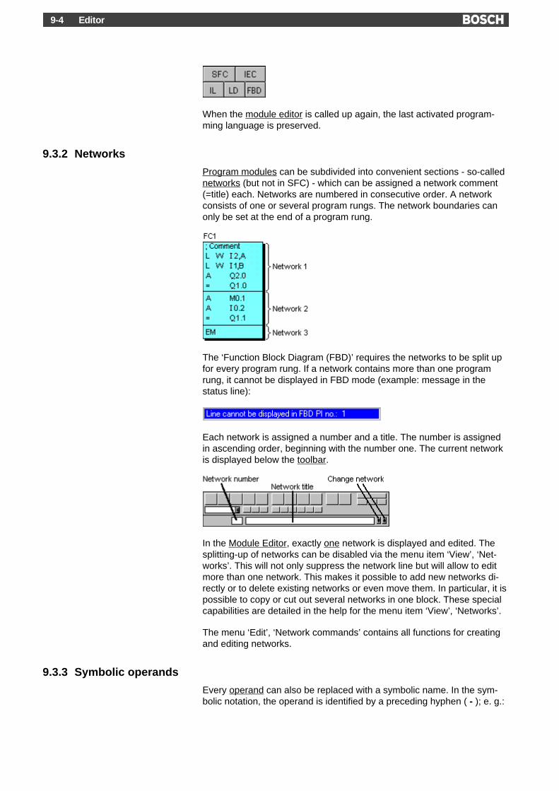
Editor9-4
When the module editor is called up again, the last activated program-ming language is preserved.
9.3.2 Networks
Program modules can be subdivided into convenient sections - so-callednetworks (but not in SFC) - which can be assigned a network comment(=title) each. Networks are numbered in consecutive order. A networkconsists of one or several program rungs. The network boundaries canonly be set at the end of a program rung.
The ‘Function Block Diagram (FBD)’ requires the networks to be split upfor every program rung. If a network contains more than one programrung, it cannot be displayed in FBD mode (example: message in thestatus line):
Each network is assigned a number and a title. The number is assignedin ascending order, beginning with the number one. The current networkis displayed below the toolbar.
In the Module Editor, exactly one network is displayed and edited. Thesplitting-up of networks can be disabled via the menu item ‘View’, ‘Net-works’. This will not only suppress the network line but will allow to editmore than one network. This makes it possible to add new networks di-rectly or to delete existing networks or even move them. In particular, it ispossible to copy or cut out several networks in one block. These specialcapabilities are detailed in the help for the menu item ‘View’, ‘Networks’.
The menu ‘Edit’, ‘Network commands’ contains all functions for creatingand editing networks.
9.3.3 Symbolic operands
Every operand can also be replaced with a symbolic name. In the sym-bolic notation, the operand is identified by a preceding hyphen ( - ); e. g.:

Editor 9-5
A -Input_1
The symbolic operand (symbolic address) is defined via so-called defini-tion lines in the program module or in the symbol file. A symbolic operandcan consist of up to 32 characters; the symbol must not contain blanks.
9.3.4 Input checks and symbol assignment
Error ID:The current line is checked following each input, and an error ID may ap-pear in the left-hand margin of the incorrect line. An associated descrip-tion for the error ID is displayed in the status line:
You can go to the next error line via the menu function ‘Edit’, ‘Go to nexterror line’.
Automatic symbol assignment:All symbols in the edited input line are checked immediately. An addi-tional assignment run at the end of the programming session is not nec-essary. Therefore, all completed files can be directly loaded into thecontroller unless the files contain error IDs. Exception: The ID > (symbolfor absolute operand unknown) does not indicate an error but is merely awarning; loading is still possible in this case.
The length and error handling in case that the symbol comment length isexceeded can be preset individually with the function switch /K.
The function key /O1 makes it possible to influence the priority of the or
9.4 Symbol file
The symbol file is used to define symbolic module names and symbolicoperand names.
The editor for the symbol file can be called up via the menu function‘File’, ‘Symbol file’ or via the Symbol Editor button or - in order to findsymbols quickly via the menu function ‘Edit’, ‘Go to symbol definition’.
After the symbol editor has been called up, a predefined controller-specific form is displayed which can be tailored to specific requirements.The symbol file is in ASCII format.

Editor9-6
Layout of the symbol fileModule definition:
All module definitions must be made together at the beginning of thesymbol file! The module definitions can be made in any order. The onlyexception is OM1 which must be set to the beginning of all module defini-tions.
Symbol lines (<TAB> = separator or ):
Type{,Memory ID} <TAB> Module name <TAB> {Comment}
In the symbol line, a (module) type is assigned the module name. Thisname must be the same as the actual module name. The memory ID R/Eis optional (default: R).
Example: OM3,I START (* Start-up module *)
Operand definition:
Operand definitions can be made in any order! In this way, individual op-erands can be logically grouped (e. g. sections of a system).
Operand <TAB> Symbolic name <TAB> {Comment}
The symbolic name can comprise up to 32 characters.
Example: I0.0 Switch_1 (* Switch 1 *)
Constant definition:
In the symbol file, it is also possible to define globally applicable con-stants.
Value <TAB> Symbolic name <TAB> {Comment}
Example: 16#FFFF START_UP_VALUE_MAX (* max. start-upvalue *)

Editor 9-7
In addition to the symbol lines, the file may contain any number of com-ment and empty lines. The maximum line length of the file is 255 char-acters. Editing is made with fixed tab stops of 8.
The length and error handling in case that the symbol comment length isexceeded can be preset individually with the function switch /K.
Error ID:The current line is checked after each character input, and an error IDmay appear in the left-hand margin of the incorrect line. The descriptionassociated with the error ID is displayed in the status line.
9.5 Data module
You can use the data modules to access data in the controller. Datamodules in the RAM area of the controller can be modified during pro-gram execution. The contents of data modules in the (E)EPROM areacan only be read.
The data module editor can be called up via the menu function ‘File’,‘Data module’ or via the Data Module Editor button.
After the data module editor has been called up, a predefined control-specific form is displayed which can be tailored to specific requirements.The data module editor can be used to edit one data module. The datamodule file is in ASCII format.
To get more information click on the desired data type in the illustrationbelow.

Editor9-8
Layout of a data moduleIn the first line of each data module, the data module length is specifiedvia the keyword LENGTH (512 bytes max.).
The line with the length specification is followed by the data lines (<TAB>= separator or ):
Data address <TAB> Data type <TAB> {Data} <TAB> {Comment}
The data address is in the range 0-511 (byte address). The addressingwidth of the data type can be used to calculate the next data address; e.g.
- BOOL 1 byte
- BYTE 1 byte
- WORD 2 bytes
- INT 2 bytes
- STRING variable
The data addresses may contain blanks but must be specified in as-cending order. Data types with a data width of 8 bits maximum (BOOL,BYTE, SINT, USINT) can also be set to odd data word addresses.
The actual data are entered either as a numeric literal or as an ASCIIstring. The specification is optional (default). Blanks and non-initializedvalues in data modules are filled with zeros ($00 for string variables)during loading. The notation conforms to the IEC 1131-3 standard.
In addition to the data lines, the file may contain any number of commentand empty lines. The maximum line length of the file is limited to 255characters. Editing is made with fixed tab stops of 8.
Error ID:The current line is checked after each character input, and an error IDmay appear in the left-hand margin of the incorrect line. The descriptionassociated with the error ID is displayed in the status line.
9.6 Text file
The editor for the text file can be called up via the menu function ‘File’,‘Text file’ or via the text editor button.
The text editor can be used to create and edit so-called ASCII text files.This can e. g. be used to view and revise print files.
All ASCII characters which are not provided directly on the keyboard ofthe programming unit can be entered by using the keys of the numerickeypad together with the key .
Eample:

Editor 9-9
You want to enter the character {.
The decimal code of the ASCII character is 123. Hold down the key and use the numeric keypad to enter the decimal code 123. Release the
key; the character { is inserted.
9.7 Batch file
A batch file can be used to group user-defined program and/or datamodules. These groups can subsequently be used for the processing ofseveral files, such as the creation of printer outputs, loading etc. Suchgroups are directly created in the editing function via the call ‘Createbatch file’.
9.8 Documentation
9.8.1 Printing of files
To create WinSPS documents, three functions are available for the re-spective data types program module, symbol and data module file (printfile SK.TXT is created automatically when the SK table is edited for theCL400 and CL500 controllers). Different print parameters can be set forthese functions to match the documents to specific requirements. Moreo-ver, the print layout and control sequences can be used to specify theformat and layout of documents.
Documentations are created by performing the steps below in the indi-cated sequence:
1 Control sequences in the program module file
2 Layout and format parameters (header, if used)
3 Set print parameters via the dialog box of the respective print function
4 Select and set-up printer
5 Output to printer or into print file
Detailed descriptions of the individual parameters are contained in thehelp for the respective dialog box.

Editor9-10
9.8.2 Print layout
Specifications for the printing of files in WinSPS-Software are determinedvia the function 'Print Layout'.
For example, any text file can be selected as a header file. This file willthen be inserted into each print page when the print documents are cre-ated. So-called keywords can be inserted into a header file which can bereplaced with the corresponding texts when the print file is created:
Keyword Meaning/Text Length&V Version (e. g. Version 1.0) 20&D Date (09/04/96) 10&T Time (08:15:20) 15&P Page number 6&S Controller name /Module 18&F Filename 9&C Controller type (e. g. CL500) 9&N Project name 9
The length in the table specifies how many characters are required forthe entry. Please take care to insert a corresponding number of blanks sothat relevant test in the line will not be overwritten.
A control file can be used to specify start and end sequences for aprinter.
A footnote (bottom line), that contains general project data, can be affixedto every page to be printed.
In addition, different layouts and character sets can be specified.
Any change in the print layout will only be effective for all subse-quently created print files or cross-reference lists. It does not affectexisting files.
To print illustrations (e.g. LD, FBD, SFC), some printer models (e.g.Hewlett Packard ® Laserjet) have to be activated with the option 'PrintTrueType as graphic' at the 'Font style/type' setting. This setting is donein the dialog box of the printer (Windows 'Settings', 'Printer').
9.8.3 Control sequences in the module file
So-called control sequences can be used in the program module file inorder to obtain a specific appearance of the printed text. They must beplaced at the beginning of a line with a preceding semicolon (commentID). Example:
;$P
The following control sequences are available:
Sequence Meaning/Function;$IL Instruction List programming language;$LD Ladder Diagram programming language

Editor 9-11
Sequence Meaning/Function;$FBD Function Block Diagram programming language;$PR+ Print program rung number;$PR- Do not print program rung number;$SK+ List including symbol comment;$SK- List without symbol comment;$SUZ+ Symbol and line comments;$SUZ- Symbol comment in line;$SBW+ Symbol comment Byte/Word address On;$SBW- Symbol comment Byte/Word address Off;$SYM Symbolic operands;$ABS Absolute operands;$80 80 characters per line;$132 132 characters per line;$P Page feed;$NOLIST Halt print for current module;$LIST Resume print for current module;$NL+ Start with network overview;$NL- Without network overview;$NZ+ Show title of network;$NZ- Hide title of network;$XNW More than one network per page;$1NW One network per page;$PL+ Show parameters list;$PL- Hide parameter list;$ZK+ Show line comments;$ZK- Hide line comments
Any change in the printer set-up will only be effective for all subse-quently created print files or cross-reference lists. It does not affectexisting files.
9.8.4 Cross-reference list
A cross reference lists which operand has been programmed in whichmodule and in which command line (instruction line). The following is dis-played for each operand:
- absolute and symbolic operand name
- symbolic name of the module in which the access takes place
- line number and program instruction of the access
- differentiation between read and write accesses
- list of (un)used I/O/M-Bit operands
- list of the symbolic and absolute bit operands
To track missing symbols or symbol comments, the finished cross-reference list includes special characters, too. The character “@” is usedwhen no symbol has been assigned to an operand. The symbol “$” isused when no symbol comment has been assigned to an operand. So,for example, you can look out for the character @ with the function‘Search’ to calculate all operands with no existing symbol one by one.

Editor9-12
9.9 Stacker - Processing log
The Stacker window is used as a processing log for WinSPS functionswhich process several files. The following functions use the Stacker win-dow to log files:
- Comparison functions between file and controller
- Functions for the printing of files
- Functions for the creation of cross-reference lists
- Loading and unloading functions
The Stacker window shows the total number of files to be processed,how many of them have already been processed and which of them haveerrors. All files to be processed are displayed with a processing result.
The Stacker window contains a Go to button which can be used to openand edit an incorrect file.
The last displayed processing log (Stacker window) which has been usedby a function to produce a listing of incorrect files can be displayed oncemore via the menu item ‘Edit’, ‘Last Stacker result’.
The processed files of the Stacker display can be viewed in one line or asa listing. The selection can be made via the function switch /P.
9.10 Connection to the PLC
The loading process, several comparison functions, the Monitor etc. re-quire a connection to the controller. This connection is established via aserial port of the computer using connection cable K16, K19 to the con-troller. The current baud rate is selected in the file presets. You can alsomake the system perform the settings automatically by selecting themenu function ‘Controller’, ‘Interface test’.
If a connection to the controller cannot be established, please check theinterface setting and the physical connection between the programmingunit and the controller.

Editor 9-13
If the WinSPS software is installed on a ZAT module, communication canbe made over the system bus.
If you own a license for the Central Programming (CP), you can connectup to 124 controllers simultaneously with the programming unit. You canget further information regarding the CP in the paragraph of this help withthe same name.
9.11 Comparison
It is possible to compare modules on the harddisk with other modules ondisk or in the controller. Various comparison functions for program anddata modules are available:
- Comparison of the entire program
- Comparison of all or a single program module(s)
- Comparison of a data module
In case of inconsistent modules or module contents, the incorrect files orfile contents, respectively, are listed. You can then directly correct thefiles.
For comparisons with modules in the controller, a connection to the con-troller must be established.
Detailed descriptions of the various comparison functions are containedin the help for the respective function (menu ‘File’, ‘Comparison’).
9.12 Load program
The function ‘Control’, ‘Load’ is used to load the programs or individualmodules into the controller. All available loading settings can be made ina dialog box.
For the CL400 or CL500, you will have to make entries in the SK tablefirst by using the function ‘Control’, ‘System coordinator’.
9.13 Changing to the Monitor
The Monitor can be called up via the menu function ‘Change’, ‘Monitor’ orthe Monitor button.
The Monitor offers the following options:
- Testing of programs
- Checking of controller and program states
- Viewing of the I/O state
- Tracing of module calls
- Forcing and manipulation of states

Editor9-14
The modules are checked before the Monitor is activated. If a switch-overinto the Monitor is not possible due to inconsistent module contents, youcan use the comparison functions (menu ‘File’, ‘Comparison’) to deter-mine which parts of the program are not consistent.
A variation of the Monitor call is a combination with the loading process.This function is activated via the menu function ‘Change’, ‘Load + Moni-tor’ or via the corresponding button.
Here, the loading process for the program module or data module file isactivated before the switch-over to the Monitor occurs. The controller isnot stopped. This procedure is the best solution for making changes to aprogram with the system running and checking them afterwards.

Installation 10-1
10 Editor – Menu functions
10.1 File Menu
This menu groups all functions which can be applied to files (e. g. open-ing, saving, insertion, printing and comparison). In addition, it allows toswitch between the different editors for modules, data modules, symboland text).
10.1.1 New/Open
This function can be used to create a new file or change the current file.Only files of the current filetype can be opened. For example, if you are inthe symbol editor, you can only open symbol files.
The drive and directory has been specified in the Presets and cannot bechanged. This is also true for the current file type.
By using the "Read-only" option, you can write protect the file, whichmeans that changes in the file cannot be saved.
A fast change of files can also be made by using the file selector box inthe toolbar.
Dialog box File OpenThis dialog box allows you to switch the current file. The drive and direc-tory are determined by the current Presets in the main menu and cannotbe changed. This is also true for the current file type. This means, if youare e. g. in the symbol editor, you can only open symbol files.
When entering the filename, you need not specify the file type.
By using the Read-only option you can write protect the file so thatchanges in the file cannot be saved.
The Network button is irrelevant because only the current ZS directorywill be processed.
A fast change of files can also be made by using the file selector box inthe toolbar.
10.1.2 Save
This function saves the currently displayed file.
10.1.3 Save as
This function can be used to save the currently edited file under a differ-ent filename.
Dialog box Save AsThis dialog box allows you to save the currently edited file under a differ-ent filename. This also offers the possibility to save the file in a directorywhich is not the current ZS directory, or even under a different drive.

Installation10-2
When entering the filename, you need not specify the file type.
10.1.4 Save all
This function saves all opened files in all editors (module, data module,symbol and text).
10.1.5 Insert file
This function allows to insert any other file into the currently displayed fileat the writing cursor position.
Dialog box Insert FileThis dialog box allows to insert any other file into the currently displayedfile at the writing cursor position. This allows to assemble a new modulefrom existing modules.
If an area has been marked before in the currently displayed file, thisarea will be overwritten with the contents of the clipboard.
If the file to be inserted is a program module file, all special control char-acters will be removed from this file so that the file can easily be insertedinto a text file or another program module file.
If the file which has to be inserted is a Sequential function chart, you caninsert it in the SFC directory, if the cursor is placed on an index field.
10.1.6 Import symbols
This function allows you to insert symbols from any file (e. g. files fromCAE systems like E-Plan and Ruplan) into the current symbol file. In thisprocess, it is checked if the symbols already exist. You can then decidefor each individual case whether you want to overwrite the symbol or not.
This command is only available in the symbol editor!
Dialog box Import SymbolsThis dialog box allows you to insert symbols from any file (e. g. files fromCAE systems like E-Plan and Ruplan) into the current symbol file. In thisprocess, it is checked if the symbols already exist. You can then decidefor each individual case whether you want to overwrite the symbol or not.
10.1.7 Compile module (ST)
This function is used to compile the currently displayed ST file. Any de-tected errors are displayed in the error display.
For more information, refer to the Help for the error display:
Please observe that all entries must be completed and the ST filemust be stored before compilation.

Installation 10-3
Shortcuts:
Toolbar:
Keyboard: + +
10.1.8 Check
This function checks the currently displayed file. If the system detects anerror, an error ID is set in the first column of the corresponding line. Thewriting cursor is positioned in the first line which contains an error. An er-ror description is displayed in the status line.
You can edit each error with the function ‘Edit’, ‘Jump to next error line’.
10.1.9 Create new project
This function serves a dual purpose. It can be used to:
1) revise existing files from the PROFI software.
2) check (i. e. symbol assignment, parameters, language conversion ifrequired) of all program modules which are specified in the symbolfile.
re 1) If you call up this function, the WinSPS software will automaticallyrecognize whether the current project contains old files of the PROFIsoftware so that these files can be revised. The files must have beencreated with version 3.0 (or later) of the PROFI software. Step 2) is thenexecuted:
re 2) If the current module files have been created with the WinSPS soft-ware, no revision will take place. During project generation, all modulefiles which are specified in the preset symbol file will be checked. Allsymbols will be checked so that symbol changes in the symbol file whichhave been made after the generation of the module files will be matched(assignment). In addition, the number of parameters for all instructionscontaining module calls will be checked. Module calls without parameterswill also be checked. If an error is detected, a Stacker window with an er-ror description will be displayed.
Project generation corresponds to the two check options ‘with symbol as-signment’ and ‘with parameter check’ of the load function (menu ‘Control’,‘Load’). This means that the Create new project function can be used tomake a check even before the loading process takes place.
10.1.10 Generate file for download
This function can be used to generate a so-called download file for se-lected controllers. This creates a loadable file with the name of the cur-rent symbol file and the file extension *.FXF. This file can be loaded intothe controller with the Dekos Development Kit.

Installation10-4
10.1.11 Compare entire program on disk with the PLC
This comparison function works on the entries of the reference list in thecontroller. All modules which are listed there are compared with the con-tents of the controller. This includes data modules so that changes in theassociated data fields can be detected.
In case of inconsistent modules or module contents, the incorrect filesare listed. You can then directly correct these files.
The comparison requires a connection to the controller. If the connectioncannot be established, please check the interface setting and the physi-cal connection between the programming unit and the PLC.
10.1.12 Compare all program modules on disk with the PLC
This comparison works on the entries of the reference list in the control-ler. All program modules which are listed there are compared with thecorresponding files on disk. Data modules are not compared, i. e.changes in the associated data fields are not detected.
In case of inconsistent modules or module contents, the incorrect filesare listed. You can then directly correct these files.
The comparison requires a connection to the controller. If the connectioncannot be established, please check the interface setting and the physi-cal connection between the programming unit and the PLC.
10.1.13 Compare one program module on disk with the PLC
For this comparison, one program module file is selected in a dialog box.This file is then compared with the corresponding module in the control-ler.
The comparison requires a connection to the controller. If the connectioncannot be established, please check the interface setting and the physi-cal connection between the programming unit and the PLC.
Dialog box Compare program module on disk with the PLC
This dialog box allows you to select a program module file. This file isthen compared with the corresponding module in the controller.
During the comparison process, you can view the processing directly in alisting of all program instructions in IL. You can then directly correct thefile.
Since the program module is directly displayed during the comparisonprocess, it is not possible to compare protected library modules.
The comparison requires a connection to the controller. If the connectioncannot be established, please check the interface setting and the physi-cal connection between the programming unit and the PLC.
Dialog box Result of comparison of program module on disk with the PLC

Installation 10-5
In this dialog box, the comparison process is logged. The left part dis-plays the program instructions (IL) of the Module on disk while the rightpart contains Module in PLC. A highlighting bar over a program instruc-tion indicates the current comparison position of the two modules. If adifference is detected, the comparison will stop.
The comparison can be continued with the Continue button, and theCancel button allows you to terminate the comparison before it is com-pleted. If you want to edit the error in the module, use the Go to button toterminate the comparison and go directly into the module.
If all program instructions are consistent between the compared modules,this result is displayed, and the comparison can be terminated with theClose button.
10.1.14 Compare two program modules on disk
For this comparison, you can select two program module files in a dialogbox. The reference file can also be selected in a different directory thanthe current ZS directory, or even on a different drive.
This comparison does not require a connection with the controller.
Dialog box Compare two program modules on disk
In this dialog box, two program module files to be compared can beselected.
The reference file can also be selected in a different directory than thecurrent ZS directory, or even on a different drive. To facilitate the modulesearch, another dialog box can be opened via the Find file button.
If the file contents are inconsistent, an error message will appear.
This comparison does not require a connection with the controller.
Dialog box Result of comparison of two program modules on disk
In this dialog box, the comparison process is logged. The left part dis-plays the program instructions (IL) of the module while the right partcontains the reference module. A highlighting bar over a program instruc-tion indicates the current comparison position of the two modules. If adifference is detected, the comparison will stop.
The comparison can be continued with the Continue button, and theCancel button allows you to terminate the comparison before it is com-pleted. If you want to edit the error in the module, use the Go to button toterminate the comparison and go directly into the module.
If all program instructions are consistent between the compared modules,this result is displayed, and the comparison can be terminated with theClose button.

Installation10-6
10.1.15 Compare one data module on disk with the PLC
For this comparison, one data module file can be selected in a dialogbox. This file will then be compared with the corresponding data modulein the controller.
The comparison requires a connection to the controller. If the connectioncannot be established, please check the interface setting and the physi-cal connection between the programming unit and the PLC.
Dialog box Compare data module on disk with the PLC
This dialog box allows you to select a data module file. This file will thenbe compared with the corresponding module in the controller.
During the comparison, you can view the processing directly in a listing ofall data. You can then directly correct the file.
The comparison requires a connection to the controller. If the connectioncannot be established, please check the interface setting and the physi-cal connection between the programming unit and the PLC.
Dialog box Result of comparison of a data module on disk with the PLC
In this dialog box, the comparison process is logged. The left part dis-plays the data lines of the Module on disk while the right part containsthose of the Module in PLC. A highlighting bar over a data line indicatesthe current comparison position of the two modules. If a difference is de-tected, the comparison will stop.
The comparison can be continued with the Continue button, and theCancel button allows you to terminate the comparison before it is com-pleted. If you want to edit the error in the module, use the Go to button toterminate the comparison and go directly into the module.
If all data lines are consistent between the compared modules, this resultis displayed, and the comparison can be terminated with the Close but-ton.
10.1.16 Compare two data modules on disk
For this comparison, you can select two data module files in a dialog box.The reference file can also be selected in a different directory than thecurrent ZS directory, or even on a different drive.
This comparison does not require a connection with the controller.
Dialog box Compare two data modules on diskIn this dialog box, two data module files to be compared can be se-lected.

Installation 10-7
The reference file can also be selected in a different directory than thecurrent ZS directory, or even on a different drive. To facilitate the modulesearch, another dialog box can be opened via the Find file button.
If the file contents are inconsistent, an error message will appear.
This comparison does not require a connection with the controller.
Dialog box Result of comparison of two data modules on disk
In this dialog box, the comparison process is logged. The left part dis-plays the data lines of the module while the right part contains those ofthe reference module. A highlighting bar over a data line indicates thecurrent comparison position of the two modules. If a difference is de-tected, the comparison will stop.
The comparison can be continued with the Continue button, and theCancel button allows you to terminate the comparison before it is com-pleted. If you want to edit the error in the module, use the Go to button toterminate the comparison and go directly into the module.
If all data lines are consistent between the compared modules, this resultis displayed, and the comparison can be terminated with the Close but-ton.
10.1.17 Compile C module
This function allows to compile (translate) a module which is written in theC high-level language, resulting in an exectutable, loadable programmodule (*.PXH). The high-level language is supported ba the PLCs PCLand ICL700.
The source for the C instructions is an ASCII text file with the extension*.C.
High-level language programming is not a part of the WinSPS basicpackage, i.e. a separate license must be obtained to use this fea-ture.
The following development packages are required and need to be in-stalled for high-level language programming:
1. WinSPS including a HLL license (Order No. 1070 077 925)
2. GNU-HLL tools for C (Order No. 1070 081 424)
3. High-level language library for PCL (Order No. 1070 081 428) or forICL700 (Order No. 1070 081 428)
10.1.18 Create C library module
This function consolidates modules which are written and compiled in C(*.PXH) into a module library. A dialog box allows to make entries for themodules and their assignment to organization modules.
The high-level language is supported by the PLCs PCL and ICL700.

Installation10-8
High-level language programming is not a part of the WinSPS basicpackage, i.e. a separate license must be obtained to use this fea-ture.
The following development packages are required and need to be in-stalled for high-level language programming:
1. WinSPS including a HLL license (Order No. 1070 077 925)
2. GNU-HLL tools for C (Order No. 1070 081 424)
3. High-level language library for PCL (Order No. 1070 081 428) or forICL700 (Order No. 1070 081 428)
Dialog box Assign library module to OM
This dialog box is used to assign modules which are written and compiledin the C high-level language (*.PXH) to organization modules and con-solidated in a module library.
In the PLCs PCL or ILC700, high-level language library modules are ref-erenced via organization modules (OMs).
In the list, enter the name of the HLL module without extension for thedesired OM. You may assign up to three files to each OB. This allowsyou to include several modules per OM in the generation, e.g. for testingyour program. After all, the entry in the symbol file determines whichmodule is accessed. The example in the illustration below explains thisrelationship:
Assignment:
Entry in symbol file:
OM51,R TEST2
OM52,R MAIN
OM53,R SUB2
In this example, 6 modules are created as library modules, but the pro-gram only accesses the modules TEST2, MAIN, and SUB2. A differentmodule can be accessed by modifying an entry in the symbol file andloading the symbol file, without having to recreate the module library.
The organization modules OM48, 49 and 50 should not be used be-cause they are reserved for Bosch library modules.

Installation 10-9
10.1.19 Print program module file
This function can be used to print one or more program module file(s).
A dialog box is displayed in which you can make additional settings.
Dialog box Print program moduleThis dialog box allows you to make the settings for the printing of pro-gram module files:
ModuleIf the option current program module is selected, only the current pro-gram module file will be printed.
If the option from symbol file is selected, all program modules which arelisted in the symbol file will be printed.
With the option from batch file, all program modules which are listed inthe batch file will be printed. This is a suitable option to print a selectionof program modules. The batch file can be selected in the adjacent se-lector box. The Set up button calls up another dialog box which allowsyou to edit the selected batch file.
Print in fileThis is used to specify an ASCII text file to be used as a print file. Youcan subsequently edit the file in the text editor and then print it (e. g. viathe Windows function ‘Execute’: PRINT LIST.TXT or COPY LIST.TXTLPT1). If you do not activate this function, the selected printer will beused.
If you exit from the dialog box by pressing the OK button, the print file iscreated or the printing process is started, respectively.
NetworksEach program module can be preceded by a Network overview as a ta-ble of contents. At the beginning of a network, the associated Network ti-tle can be printed. In order to reduce the size of the print file, you candisable the option One network per page so that several networks areprinted on one page.
Parameter listFor parametrized program modules it is possible to print a description ofthe pass parameters.
RepresentationThis allows you to select the programming language for the print file: In-struction List, Ladder Diagram or Function Block Diagram. To printillustrations (e.g. LD, FBD, SFC), some printer models (e.g. HewlettPackard ® Laserjet) have to be activated with the option 'Print TrueTypeas graphic' at the 'Font style/type' setting. This setting is done in the dia-log box of the printer (Windows 'Settings', 'Printer').

Installation10-10
LayoutWith the option Output RG number, you can add the current RG numberbefore each new program rung. In the command lines, the Operands canbe displayed either symbolic or absolute, and the Line comment can besuppressed if required.
Symbol commentThe option with symbol comment means that the symbol comment isprinted for bit operands. Additionally, the symbol comment can alsoprinted with byte or word operands. If you activate the option 'Linecomment' and print 'with symbol comment', the command line will beoverwritten. If you choose the option end of page, symbol comments andline comments will be printed.
When the SK Table (menu item ‘Control’, ‘System Coordinator’) is editedfor CL400 or CL500 controllers, a text file SK.TXT will automatically becreated. This file should be included in the printout for a full documenta-tion of the project.
Additional print options - such as page size, header and control file etc. -can be set via the menu function ‘File’, ‘Printer set-up’.
10.1.20 Print data module file
This function can be used to print one or more data module file(s).
A dialog box is displayed in which you can make additional settings.
Dialog box Print data moduleThis dialog box allows you to make the settings for the printing of datamodules:
ModuleIf the option current data module is selected, only the current datamodule file will be printed
If the option from symbol file is selected, all data modules which arelisted in the symbol file will be printed.
With the option from batch file, all data modules which are listed in thebatch file will be printed. This is a suitable option to print a selection ofdata modules. The batch file can be selected in the adjacent selectorbox. The Set up button calls up another dialog box which allows you toedit the selected batch file.
LayoutThe Line comment in the data module can be suppressed if required.
Print in fileThis is used to specify an ASCII text file to be used as a print file. Youcan subsequently edit the file in the text editor and then print it (e. g. viathe Windows function ‘Execute’: PRINT LIST.TXT or COPY LIST.TXTLPT1). If you do not activate this function, the selected printer will beused.

Installation 10-11
If you exit from the dialog box by pressing the OK button, the print file iscreated or the printing process is started, respectively.
Additional print options - such as page size, header and control file etc. -can be set via the menu function ‘File’, ‘Printer set-up’.
10.1.21 Print symbol file
This function is used to print the symbol file.
A dialog box is displayed in which you can make additional settings.
Dialog box Print symbol fileThis dialog box allows you to make the settings for the print file for theoutput of the current symbol file.
Print in fileThis is used to specify an ASCII text file to be used as a print file. Youcan subsequently edit the file in the text editor and then print it (e. g. viathe Windows function ‘Execute’: PRINT LIST.TXT or COPY LIST.TXTLPT1). If you do not activate this function, the selected printer will beused.
If you exit from the dialog box by pressing the OK button, the print file iscreated or the printing process is started, respectively.
Additional print options - such as page size, header and control file etc. -can be set via the menu function ‘File’, ‘Printer set-up’.
10.1.22 Print Sequential function chart
With this function, you can print the Sequential function chart file. Here,the current position decides on the printing process:
Positions:- Table of contents
- Sequence level
- Automatic branch (MADAP)
- Manual branch (MADAP)
Example: You are on the sequence level in the automatic branch. If younow activate the function ‘Print’, ‘Sequential function chart’, ‘Print all’, allsequences (and swap-outs) of the automatic branch are printed.
With the function ‘Print Content element’, only the current sequence orthe current sequence description is printed. With ‘Print All’, all se-quences or the complete directory are printed – depending on the posi-tion.
You can insert manual page breaks at different positions of the se-quence, so that a formatted version on the printer is possible (menufunction ‘Edit’, ‘Insert pagination’).

Installation10-12
Additional print options - such as page numbers, page size, header andcontrol file etc. - can be set via the menu function ‘File’, ‘Printer set-up’.
To print illustrations (e.g. LD, FBD, SFC), some printer models (e.g.Hewlett Packard ® Laserjet) have to be activated with the option 'PrintTrueType as graphic' at the 'Font style/type' setting. This setting is donein the dialog box of the printer (Windows 'Settings', 'Printer').
10.1.23 Print layout
A dialog box allows you to make various settings for the printout ofWinSPS files.

Installation 10-13
Dialog box Print layoutIn this dialog box, all global settings for the printing of files of the WinSPSsoftware anf for the creation of cross-reference lists are made:
Document infoThe header file can be any ASCII file. The file will appear as a header onevery printed page. If no header file is to be used, you can exit from theinput field without making any entry. In this case, default header lines willbe inserted. The header file must be in the current ZS directory. Formatof header file:
The control file in ASCII format contains the printer start and end se-quences. The WinSPS software will insert these sequences into everycreated print file. If no printer sequences are to be used, you can leavethis input field without making an entry. The control file must be in thesame directory as the WinSPS software. The file must be of the .ESC filetype and be structured as follows:
The area of the start or end sequences is introduced by the keyword[START] or [END], respectively. The control sequence is written in oneline and consists of two hexadecimal numbers each which are separatedby a comma. It is not permitted to use embedded separators such as<TAB> or <blank>. Incorrect control files are rejected during printing, andan error message is displayed.
Example of a control file
[START]
1B,54,38,45
[END]
1B,55,45,1B,32
Line infoThis is used to specify the format of the print file (80 or 132 charactersper line).
Character setThe character set can be selected for the connected printer. You canchoose between the 8-bit IBM compatible character set, the 8-bit ANSIcharacter set used by Windows, and the 7-bit US-ASCII character set.Block graphic characters and "Umlaute" are converted into characters ofthe selected character set during printing.
Page infoThis is used to specify a number of lines per page.
Bottom lines of the print pageA footnote (bottom line), that contains general project data, can be affixedto every page to be printed (see diagram). This footnote does not appearwhile printing in a file (go to: Printing Functions).

Installation10-14
You can print out a copyright statement containing your own companydetails. In addition, you can predetermine general titles, an author andan instruction number. All other fields in the footnote are already pre-determined and cannot be changed.
Any change in the print layout will only be effective for all subse-quently created print files or cross-reference lists. It does not affectexisting files.
10.1.24 Cross-reference
A cross-reference lists which operand has been programmed in whichmodule and in which command line (instruction line). The following is dis-played for each operand:
- absolute and symbolic operand name
- symbolic name of the module in which the access takes place
- line number and program instruction of the access
- differentiation between read and write accesses
Settings for the creation of the cross-reference list are made in a dialogbox.
Dialog box Create cross-referenceThis dialog box allows you to make settings for the creation of cross-reference lists:
ModuleIf the option current module is selected, only the current program ordata module file will be included in the cross-reference.
If the option from symbol file is selected, all program and data moduleswhich are listed in the symbol file are included in the cross-reference.
With the option from batch file, all program and data modules which arelisted in the batch file will be included in the cross-reference. This is asuitable option to use a selection of modules. The batch file can be se-lected in the adjacent selector box. The Set-up button calls up anotherdialog box which allows you to edit the selected batch file.
Cross-reference fileThis is used to specify an ASCII text file which is to be used as a cross-reference file. It is assigned the fixed file type .QV. The cross-referencefile can then be printed out (e. g. via the Windows function ‘Execute’:PRINT CROSS.QV or COPY CROSS.QV LPT1) or edited in the texteditor.
The cross-reference file will be created when you exit from the dialog boxwith the OK button.

Installation 10-15
OperandsThis is used to select whether all operands or a single operand shall beincluded in the cross-reference. A single operand can be specified in theinput field in absolute or symbolic form (with a leading hyphen!). Fur-thermore, you can add a comprehensive Configuration list into thecross-reference. This list shows in tabular form the operands which youhave access to either/or by reading/writing or not at all.
SortYou can sort the cross-reference lost to absolute or symbolic operands.
To track missing symbols or symbol comments, the finished cross-reference list includes special characters, too. The character “@” is usedwhen no symbol has been assigned to an operand. The symbol “$” isused when no symbol comment has been assigned to an operand. So,for example, you can look out for the character @ with the function‘Search’ to calculate all operands with no existing symbol one by one.
When the SK Table (menu item ‘Control’, ‘System Coordinator’) is editedfor CL400 or CL500 controllers, a text file SK.TXT will automatically becreated. This file should be included in the printout for a full documenta-tion of the project.
Additional print options for the cross-reference file - such as page size,header and control file etc. - can be set via the menu function ‘File’,‘Printer set-up’.
10.1.25 Create sequence
Before the loading of a SFC file into the controller, the sequence must begenerated. It can be adjusted immediately before loading in the load dia-log box. You can also create intermediately, for example to check yourinputs. During the creating process, the sequences are changed into ILinstructions and inserted into program modules. Different symbols of thesequence are inserted into the symbol file.
In a dialog box, further inputs can be done and the creation can bestarted.
Dialog box Create sequenceBefore the loading of a SFC file into the controller, the sequence must begenerated. It can be adjusted immediately before loading in the load dia-log box. You can also create intermediately, for example to check yourinputs. During the creating process, the sequences are changed into ILinstructions and inserted into program modules. Different symbols of thesequence are inserted into the symbol file.
OptionsThe option Command output in extra module is only possible in theprogramming type step marker technique. By selecting this option, theprogram module AUSGABE.PXO is produced additionally. It collects allstep actions which influence the output.
With the option Create cascade call in OM1 you can choose that allmodule calls which are necessary for the sequence, are automatically in-serted into the organization module OM1. OM1 will be overwritten.

Installation10-16
The project will be created before the creation of the sequence, if you ac-tivate the option with ‘Rebuild all’. You can get further information in theappropriate chapter.
The controller CL200 additionally produces the binary conditions Logical0 and Logical 1. They will be illustrated on the reserved markers M0.0 (-LOG0) and M0.1 (-LOG1). These conditions are already realized in allother controllers via special markers.
Programming typeThe programming type MADAP or step marker technique is chosen viathe menu function ‘Toolbox’, ‘Inputs’.
Memory ID R/E in the symbol file (CL200 only)Some program and data modules are registered automatically with thecreation. Here, you can determine which Memory ID will be assigned tothe files. With the combination RAM/EPROM, the program modules getthe ID EPROM and the data modules get the ID RAM.
Please remember that the Memory IDs can only be assigned for thosefiles which have been added to the symbol file. Example: After the crea-tion with the option ‘EPROM’, you have to change the ID E in the symbolfile for OB1 manually.
10.1.26 Change to module editor
This function is used to change to the current program module file in themodule editor. The WinSPS software retains the file of the previously ac-tivated editor in the memory so that any changes are preserved. Whenyou exit from the editors, a safety prompt is displayed for all modifiedfiles.
When you change from the symbol editor to the module editor, all sym-bols will be updated (assignment of new, deleted and modified symbols).
10.1.27 Change to data module editor
This button can be used to switch to the current data module file in thedata module editor. The WinSPS software retains the file of the previ-ously activated editor in the memory so that any changes are preserved.When you exit from the editors, a safety prompt is displayed for all modi-fied files.
10.1.28 Change to symbol editor
This function is used to change to the current symbol file in the symboleditor. The WinSPS software retains the file of the previously activatededitor in the memory so that any changes are preserved. When you exitfrom the editors, a safety prompt is displayed for all modified files.
If you leave the symbol editor (change into the module, data module ortext editor), the symbol file will be checked. If an error is detected, awarning will be displayed.

Installation 10-17
10.1.29 Change to text editor
This function is used to change to the current text file in the text editor.The WinSPS software retains the file of the previously activated editor inthe memory so that any changes are preserved. When you exit from theeditors, a safety prompt is displayed for all modified files.
10.1.30 Properties
This function can be used to display additional data about the currentprogram module, data module or symbol file:
- Name and comment- Date and time- Version number
The comment and the version number can be entered via the “Parameterhead editor”.
10.1.31 File selector
This is a list of the files which have been edited last. If you select a file, itwill be opened for editing, and the corresponding editor will also be calledup.
You can customize the number of files, that are displayed in this menu,with the function switch /Fn. 4 files are usually listed (/F4).
10.1.32 Exit
This can be used to exit from the WinSPS software and return to Win-dows. All modified files can be saved after a request (depending on thesetting of function switch /A).
10.1.33 Back to sequence
The level for the input of the PLC instructions is finished and you can getback to the sequence. All inputs are checked and integrated into the se-quence.
The instructions are only visible on the PLC level, whereas on thesequence level, the element „PLC“ is indicated as a step action.

Installation10-18
10.2 Edit Menu
This menu contains all functions which can be used to edit files.
This includes the following functions:
- Undo/Redo last edit
- Cut, Copy and Paste
- Find and Replace
- Network commands
- Editing of parameter lists and library modules.
10.2.1 Undo
This function can be used to undo the previous text editing step. Everyediting which has been cancelled with the "Undo" function can be re-stored with the "Redo“ function.
Example: You have inadvertently deleted a highlighted area (e. g. withthe key ). You can then use the "Undo" function to reinsert the de-leted area into the file. If you subsequently use the "Redo“ function, thehighlighted area will be deleted again.
In all editors (except LD and FBD), you can undo/redo - depending on thesetting of function switch /U - up to 99 consecutive text editing steps.
10.2.2 Redo
A previous text edit can be cancelled with the "Undo" function. By usingthe "Redo" function, you can restore the original state.
Example: You have inadvertently deleted a highlighted area (e. g. withthe key ). The "Undo" function will reinsert the deleted area into thefile. If you subsequently use the "Redo“ function, the highlighted area willbe deleted again.
In all editors (except LD and FBD), you can undo/redo - depending on thesetting of function switch /U - up to 99 consecutive text editing steps.
10.2.3 Last Stacker result
This function can be used to edit several consecutive files which containerrors.
The last displayed processing log (Stacker window) which has been usedby a function to produce a listing of incorrect files can be displayed oncemore. Each Stacker window contains a Go to button which you can useto open an incorrect file and edit it.
The following functions use the Stacker display to log incorrect files:
- All comparison functions between file and controller
- All functions for the creation of cross-reference lists

Installation 10-19
- Load and Unload functions (see illustration example)
The processed files of the Stacker display can be viewed in one line or asa listing. The selection can be made via the function switch /p.
10.2.4 Repeat last command
You can repeat the last input in the Sequential function chart (SFC).
Example: You want to add three ‘Set (S)’ actions to a step action. Pleaseadd the step action ‘Set (S)’ once, and then call up the function ‘Repeatlast command’ twice.
You can undo an accidentally made repetition with the function “Undo”.
10.2.5 Cut
This function copies the highlighted block area into the clipboard and de-leted (cut out) from the current editor. You can then insert the contents ofthe clipboard at another position or even in a different file. This procedureis the same as the "moving" of texts.
The contents remains stored in the clipboard - and can thus be insertedany number of times - until another highlighted area is saved in the clip-board (the contents will even be retained after you exit from the WinSPSsoftware!).
Move or copy operations can also be performed very easily by using themouse operation Drag & Drop .
10.2.6 Copy
This function copies the highlighted block area into the clipboard You canthen insert the contents of the clipboard at another position or even in adifferent file.
The contents remains stored in the clipboard - and can thus be insertedany number of times - until another highlighted area is saved in the clip-board (the contents will even be retained after you exit from the WinSPSsoftware!).
Move or copy operations can also be performed very easily by using themouse operation Drag & Drop .

Installation10-20
10.2.7 Paste
The contents stored in the clipboard is inserted at the current writing cur-sor position.
If an area has been marked before, this area will be overwritten with thecontents of the clipboard.
The contents remains stored in the clipboard - and can thus be insertedany number of times - until another highlighted area is saved in the clip-board.
Move or copy operations can also be performed very easily by using themouse operation Drag & Drop .
10.2.8 Change IL to comments
You can change a marked area in the IL programming language to com-ments. All marked lines are preceded by the comment sign “;”.
Remember to mark the changed lines from line start to line start. Thebest way to achieve this is to put the cursor to the left of the instruction
line (it changes its form ), then start to mark, and finally drag the cur-sor down vertically.
You can change marked comment lines back to IL lines by using thefunction ‘Change comments to IL’.
10.2.9 Change comments to IL
You can change a marked area of comment lines in the IL programminglanguage to IL lines.
Remember to mark the changed lines from line start to line start. Thebest way to achieve this is to put the cursor to the left of the comment line
(it changes its form ), then start to mark, and finally drag the cursordown vertically.
You can change marked IL lines back to comment lines by using thefunction ‘Change comments to IL’.
10.2.10 Go to PLC instructions for step
With this call, you get to the PLC level for the current step of a sequence.The inputs can only be made on this level. You can put in the PLC in-structions in the IL, LD or FBD programming languages.
You can exit the PLC level with the menu function 'File', 'Back to se-quence' and go back to the sequence. The PLC instructions are saved inone UAWLSTEP.PXO file which is especially made for it. The PLC in-structions are checked and inserted to the beginning of the current se-quence (not visible in the SFC editor!).
The instructions are only visible on the PLC level.

Installation 10-21
You can recognize existing PLC instructions for the step by means of asign (see illustration). To reset a characterization, all PLC instructions ofthe current step have to be deleted.
Contrary to the 'Step action PLC instructions', the instructions are exe-cuted unconditionally.
10.2.11 Go to FC <K_BETRA>
With this function, the FC K_BETRA.PXO is called up. It will automati-cally be called up if the module does not exist. The call-up from the SFCdirectory can only be made, when the cursor is on the index field of a se-quence. The illustration is in the IL. The positioning happens in the net-work, which includes the data of the current sequence.
By using the menu function ‘File’, ‘Back to sequence’, you can leave themodule and go back to the directory. The changes are saved after acheck and a request in the file K_BETRA.PXO.
10.2.12 Insert pagination
You can insert manual pagination to any positions of the sequence, sothat a formatted version on the printer is possible. Pay attention to thefact that page breaks can not be inserted within elements. If you click onthe line of the pagination and move the mouse cursor upwards or down-wards while holding the mouse button, you can move it. On this line, thepagination can be deleted with the button .
Shortcut:Keyboard: +
10.2.13 Create/Delete diagnosis marker
This function of the sequential function chart is especially made for theMADAP programming to assign a diagnosis text to a diagnosis marker.
To edit or to delete a diagnosis text the cursor must be on an insertionposition of the BEFA condition or transition.
You can not insert a diagnosis marker to a position with a complex logicaloperation. WinSPS controls these positions independently and does notallow you to insert here.
You can recognize already available diagnosis texts by a small dagger inthe branch (see illustration).

Installation10-22
Dialog box Text for DiagnosisInsert any text for the MADAP diagnosis text to the edit field and confirmthe with OK. Use Delete to delete a diagnosis marker. The text is keptand can be reactivated by the next setting of a diagnosis marker.
You can recognize already available diagnosis texts by a small dagger inthe branch (see illustration).
10.2.14 Find
This function can be used to find specific pieces of text in the current file.
Dialog box FindThis function can be used to find specific pieces of text in the current file.
If the option Whole word only is enabled, a character string is only find ifit is enclosed in blanks or tabs etc., e. g.:
Find: Bus
Found: Bus, bus, BUS
Not found: Busmaster, busdriver, PROFIBUS
If this option is disabled, the string is also found as part of a word.
You can choose to respect upper/lowercase during searching, e. g.:
Find: Bus
Found: Busmaster, Bus
Not found: busdriver, PROFIBUS
Searching for the specified string is always made from the current posi-tion of the writing cursor and depending on the direction Search up ordown.
This dialog box will remain open until you click on the Cancel button.This allows you to make any number of search runs. While searchingtakes place, you can make inputs in the editor.
10.2.15 Replace
This function can be used to find specific pieces of text in the current fileand replace them with a different text.

Installation 10-23
Dialog box ReplaceThis function can be used to find specific pieces of text in the current fileand replace them with a different text.
The specified string is always searched (and replaced) from the currentposition of the writing cursor towards the end of the file.
The found string will be replaced if you click on the Replace button. If youdo not want to replace the current found string, you can proceed to thenext search run with the Search next button. With the Replace all but-ton, you can replace all found strings without stopping.
If the option Whole word only is enabled, a character string is only find ifit is enclosed in blanks or tabs, e. g.:
Find: Bus
Found: Bus, bus, BUS
Not found: Busmaster, busdriver, PROFIBUS
If this option is disabled, the string is also found as part of a word.
You can choose to respect upper/lowercase during searching, e. g.:
Find: Bus
Found: Busmaster, Bus
Not found: busdriver, PROFIBUS
The specified string is always searched (and replaced) from the currentposition of the writing cursor towards the end of the file.
This dialog box will remain open until you click on the Cancel button.This allows you to make any number of replacements. While searchingand replacing takes place, you can make inputs in the editor.
10.2.16 Find operand address (Single cross reference)
This function allows you to find a specific operand in the current programmodule or symbol file (e. g. I14.3). The operand address is specified in adialog box.
Dialog box Show all found operandsWith this function, a certain operand can be searched in all programmodule files (e.g. I14.3). This address can be put in absolutely or sym-bolically (with leading hyphen!). You can also search absolute operandstruncated. Example: By editing 'I14', the operand addresses from ‘I14.0’to ‘I14.7’ and the accesses to ‘I14’ (Byte and Word) are searched for. Thesearch begins immediately with the input.
The list shows the module name, the PI number, the instruction and theoperand (absolutely and symbolically), and the access read or write tothe operand.

Installation10-24
With the button Go to, you can call up a module and jump to the oper-and. With the button Refresh, the search will be repeated. This dialogbox is open until the button Close is activated.Thus, any number ofsearching processes can be made consecutively.
Dialog box Find operand address (Symbol file)
This function allows you to find a specific operand in the current symbolfile (e. g. I14.3). The address can be specified in absolute or symbolicform (with leading hyphen!).
Searching for the operand address will always take place from the cur-rent position of the writing cursor towards the end of the file.
This dialog box will remain open until you click on the Cancel button.This allows you to make any number of search runs.
10.2.17 Go to error line
The WinSPS software automatically checks the module, data module orsymbol file for input errors as soon as the input is made. If errors are de-tected, an error ID will be set in the first column.
This function allows you to go to the next line which contains an error.The status line displays a description of the error.
10.2.18 Go to PI no.
This function allows you to directly access one of the program instruc-tions (PI) which are numbered consecutively. The number is entered in adialog box.
This function can only be applied to program modules.
Dialog box Go to PI no.This function allows you to directly access one of the program instruc-tions (PI) which are numbered consecutively. The current PI number isdisplayed in the status line.
10.2.19 Go to symbol definition
A symbol definition can be found quickly using this function. The defini-tion can either be found in the symbol file or - in the form of a definitionline - in the program module. Therefore one goes to the symbol file i.e. tothe position of the definition line.
This function can only be used in program modules on symbolic oper-ands.
This function can also be found in the context menu, which can bereached via the right mouse button.
10.2.20 Delete line in declaration table (ST)
This function deletes the current table line in the variable declaration orthe type definition in the ST Editor.

Installation 10-25
Shortcuts:
Toolbar:
10.2.21 Global data types
This function opens a dialog box in which global user-defined (derivative)data can be entered in tables. This function is only available in the Sym-bol editor.
However, local data types can be entered e. g. in the declaration tablesof the ST Editor .
Shortcuts:
Toolbar:
Dialog box Global data typesThis dialog box can be used to enter global user-defined (derivative)data. This function is only available in the Symbol editor.
However, local data types can be entered e. g. in the declaration tablesof the ST Editor .
On the left side, all global type definitions are displayed. There are threeclasses of data types:
1. TYPE: Basic types
2. STRUCT: Data structures
3. ENUM: Enumerations
To create new types, click on the corresponding button, e. g. .
To delete data types, click on the button .
A newly created data type is initially named “New type”. Please changethis name into the desired type designation.
10.2.22 Edit network title
Program modules can be subdivided into convenient sections - so-callednetworks which can be assigned network comments (= titles). Networksare numbered in consecutive order. A network comprises one or moreprogram rungs. The network boundaries can only be set at the end of aprogram rung.
The name is entered or changed in a dialog box.
The network title is displayed next to the network number below the tool-bar. The network numbering is not stored in the file but is created in eachcase. The display can be suppressed via the menu function ‘View’, ‘Net-works’.

Installation10-26
10.2.23 Insert before network
Inserts a new, empty network before the current network. The numberingis changed so that all subsequent network numbers are increased byone.
The writing cursor is placed inside the new network.
10.2.24 Insert after network
Inserts a new, empty network after the current network. The numbering ischanged so that all subsequent network numbers are increased by one.
The writing cursor is placed inside the new network.
10.2.25 Delete network
This deletes the current network and its contents. All subsequent net-works are moved upward and their numbers are decreased by one.
10.2.26 Split network
This splits the current network at the position of the writing cursor so thatone network becomes two.
The program instructions which have been after the writing cursor beforethe network split are placed into a new network. This network has no titleyet.
All subsequent networks are moved forward and their numbers are in-creased by one.
10.2.27 Join with previous
This joins the current network with the previous network so that both net-works become one. The title of the previously current network is insertedinto the comment line at the joining position.
All subsequent networks are moved upward and their numbers are de-creased by one.
10.2.28 Join with next
This joins the current network with the next network so that both networksbecome one. The title of the next network is inserted into the commentline at the joining position.
All subsequent networks are moved upward and their numbers are de-creased by one.

Installation 10-27
10.2.29 Create networks automatically
This function can be used to perform a subsequent, automatic subdivi-sion of a program module into networks. The network boundaries are setat the end of a program rung. The networks do not have titles yet.
10.2.30 Delete all network commands
This function removes all network IDs from a program module so that allprogram instructions are contained in a single network. This will not de-lete the contents.
10.2.31 Create library module
You can use this function to create a library module from the current pro-gram module. Library module files are protected program module files.Contrary to the usual program module, a library module only consists of acompact, executable machine code and may also contain a parameterlist. This machine code offers the advantages that is can be processedfaster during loading and that it offers a protection against viewing andmanipulation by the user.
The current module file must be error-free. The WinSPS software createsan additional file with the same filename and the file type .PXL. This filecannot be edited in the Editor. If you want to make changes to the librarymodule, you will have to edit the original module file (file type .PXO) firstand then call up the function ‘Create library module’ again. Both files willreceive the same date/time tag to facilitate revision control.
If the corresponding original program module file (.PXO) does notexist, it is not possible to edit the library module file (.PXL). Thisprotects (locks) the file against changes. Keep the original file, e. g.on floppy disk!
If you want to create a universal library module which can be used inde-pendent of the current controller, you will need to structure the module sothat it is not dependent on other modules of the project. In particular, themodule must not access symbols which are defined in the current symbolfile. For this reason, you can only use symbolic operands which havebeen specified via definition lines in the (library) module file. Input andoutput parameters are defined via the parameter list.
To allow the use of the library module for multiple projects, the WinSPSprovides a special library directory (BOSCH.BIB) into which the librarymodules can be copied .
If the same file exists both in the directory BOSCH.BIB and in thecurrent project directory, the file in the project directory will takepriority. If both a .PXL and a .PXO file of the same date exist in thesame subdirectory, the .PXL file will always be used.
If there are errors in the program sequence, three lines of the error posi-tion can be displayed with the function 'Info status' of a library module.
Installation10-28
10.2.32 Call up parameter list
This function can be used to place an existing parameter list of anothermodule as a module call to the current position of the writing cursor. Themodule description can be appended.
In particular with the programming language ST, this allows the creationof instances of function blocks.
You can make additional settings in a dialog box.
Dialog box Call up parameter list
Program moduleThis specifies the program module whose parameter list is to be used.
Module callDifferent kinds of module calls (call conditions) are available, dependingon the controller type.
DescriptionA module description which may be contained in the program module canbe appended. The module description is entered in the parameter headereditor (menu item ‘Edit’, ‘Edit parameter list’).
Dialog box Select moduleIn this dialog box, you can select a module which will then appear as amodule call at the current position of the insertion mark.
You can select a module from the list of all function blocks (FUNC-TION_BLOCK).
Module callOnly the unconditional module call CM is possible at this time.
After selecting a module, click on the ‘Continue’ button to proceed to thenext dialog box Instantiation:
Here you can obtain additional information about the ST module call:
Dialog box Select instanceThis dialog box is used to assign an instance to the module which hasbeen selected in the previous step. This mechanism allows the creationof modules “with a memory”.
All instances found can be used to obtain a listing of all instances thatexist for this module. You can either select an instance from this list orenter a new instance name. This name must comply with the designatorconventions of IEC 61131-3.

Installation 10-29
Click on the ‘Continue’ button to call up the next dialog box for the as-signment of input and output parameters:
Here you can obtain additional information about the ST module call:
Dialog box Assign input and output parameters
This dialog box is used to assign actual parameters to the instance thathas been selected in the previous step.
The displayed listing includes all declared input and output variables withtheir Names and Data types. In the column Actual parameters, youneed to enter either an absolute value or a variable.
The variables must be declared in the symbol file!
Clicking on the ‘Proceed’ button will insert the module call into the currentmodule file. In this process, WinSPS will create different entries in theEditor and – not visible here – in the symbol file. Do not change theselines, in particular the comment lines!
Here you can obtain additional information about the ST module call:
10.2.33 Edit parameter list
The parameter list makes it possible to program parameter modules withsymbolic operands. This means that symbolic operands can be used in-stead of the absolute operands P0 through.
The parameters can be entered or changed in a dialog box.
Dialog box Parameter header editorThe parameter header editor can be used to program parameter moduleswith symbolic operands. This means that symbolic operands can be usedinstead of the absolute operands P0 through Pn. In addition, the use ofparameters is checked directly at the time of input so that incorrect pa-rameters are immediately identified.
Various input fields are available for data input. All inputs are acceptedfor the currently marked parameter in the parameter list.
Data typeThe data type comforms to IEC 61131-3. The following relationships ap-ply:
ANY Format-less parameterBYTE Byte attributeBOOL Bit attributeCOUNTER Counter numberCVALUE Counter valueDM Data module numberDWORD Double-word attributeFC Program module numberOPT Format-less parameter;

Installation10-30
only possible at end of parameter listPTR Pointer to an operandTIMER Timer loop numberTVALUE Timer constant/Timer valueWORD Word attribute
The availability of these data depend on the controller.
The parameter types are checked in the module.
In the case that a function requires a higher or lower number of parame-ters, these can be declared with the data type OPT. This parameters willnot be checked. They are only permitted at the end of the parameter list.
Variable nameThis specifies the symbolic name of the operand. The operand is validonly locally in the parameter module.
Input/Output (direction of data flow)You can choose between three directions of data flow:
VAR_INPUTInput parameter. The operand is of the read-only type.This is checked when the parameter is used.
VAR_OUTPUT Output parameter. The operand is of the write-onlytype. This is also checked when the parameter is used.
VAR_IN_OUT Read or write is possible.
CommentYou can specify any comment for each parameter.
Parameter listThis shows the parameters. Two lines are used for each parameter. Thefirst line contains the parameter number, the data type, the variable nameand the direction of data flow. The parameter number is created auto-matically. The second line contains the parameter comment.
The currently marked (highlighted) parameter can be removed from thelist with the Delete button. The Insert button is used to insert a new pa-rameter before or after the current parameter, depending on whether thefirst or the second line of the parameter is highlighted. You may then editthe new parameter by using the input fields.
To assign an arbitrary description to the module, you can use the De-scription button to open another dialog box in which you can enter atext. This description can be inserted into the calling module for a modulecall (see menu item ‘Edit’, ‘Call up parameter list’).
VersionA function module can be provided with a version identification (1.0 to8.7). Pre-released versions can be characterized as alpha, beta, andgamma versions. Thus, you can distinguish standard function moduleswhich have similar names. Library modules can be characterized thesame way.

Installation 10-31
Ann.: The version identification is also loaded into the controller. The en-tries in the field Version Comment are only saved with the module onthe harddisk; i.e. they are not taken over into the controller.
The version identification can be looked at with the function 'Controller','Reference list'. All previously edited function modules automatically carrythe V1.0 version.
The button Accept can be used to accept (load) a parameter list fromany other program module. A file selector box is displayed for this pur-pose.
If you click on the OK button, the inputs are checked and - if correct - in-serted into the module file.
10.2.34 I/O configuration (OM3)
Here you can configure the input and output modules of the CL150 orRM65-DP.
A dialog box is used to enter or modify the configuration data.
Dialog box I/O ConfigurationThe dialog box for the configuration of the input and output modules ofthe CL150 or RM65-DP is subdivided into three areas:
1) On the left side, the modules and I/O addresses are configured. TheWinSPS software automatically writes this configuration into the organi-zation module OM3. Every time this configuratio is called up, the contentsof OM3 are read and displayed in this area. The filename for OM3 mustbe specified in the symbol file.
Example: OM3,R IO_CONF ; I/O configuration module
2) In the top right part, a list of available modules is displayed. From thislist, you can select the modules to be included in the configuration.
3) The bottom right part contains the list of the available inputs and out-puts.
The configuration can be edited quickly and conveniently. A hierarchicalstructure is displayed in each case (similar to Windows Explorer), whichis especially useful for copying and moving modules and PLC addresses(Drag & Drop). Just open the desired folder (+), and drag the element(module, input or output) to the desired position in the configuration list.We have prepared a little video demo to show you this process (source:WinDP help; the same process is used for the configuration of slaves).Click on this button:
After completing the configuration, you can transfer it to the organizationmodule OM3 by clicking on OK. Using the load functions, the OM3 canbe loaded into the PLC for subsequent activation.
Cancel cancels all entries.

Installation10-32
Reading the I/O configuration of the connected PLCThe option PLC contents establishes a connection to the controller,reads the actual configuration and displays it together with the (nominal)configuration. You can then compare both lists and accept the actualstate via Drag & Drop into the nominal configuration.
Label printingYou can print labelsfor the I/O modules. The labels are available on pre-punched adhesive film and can be printed with any laser printer.
Before you can print labels, you need to create the labels for the desiredmodules. To do so, position the cursor (writing mark) in the configurationlist into the designation field of the module and click on the Label button.All modules which are marked in this way will be included in the print listupon the next call of the Print label. The list will be deleted when the la-bels have been printed or when the label printing dialog is terminated.
Additional optionsThe Enable Module check option allows to check the identity of themodules. For example, if you have entered an output module "8D / 2A" inthe configuration but a module "8D / R" is connected to the controller, anerror message will be generated. The controller will remain in "Stop" inthis case.
With the Modules only option, the display of I/O information is sup-pressed in the configuration list. This provides a clearer overview of themodule configuration.
Dialog box Print Labels B-IOHere you can print labelsfor the I/O modules. The labels are available onpre-punched adhesive film and can be printed with any laser printer.
Before you can print labels, you need to create the labels for the desiredmodules. To do so, position the cursor (writing mark) in the configurationlist into the designation field of the module and click on the ‘Label‘ button.All modules which are marked in this way will be included in the print listupon the next call of the Print label function. The list will be deleted uponprinting of the labels or upon termination of the print label dialog.
I/O representationHere you can choose whether you want to print the I/O addresses in ab-solute or/and symbolic form. The window on the right side gives an im-pression how the final label will look.
Label position on filmIf you want to print on a film on which some labels have already beenprinted, you can use this function to select a start position for the labels.The setting can be checked via the button Assignment ...:
Positions on the film where labels will be printed will be shown as “as-signed“. If a start position has been specified, only labels which will beprinted will be marked as “assigned”. Labels will first be printed from leftto right. At the end of a line, printing will continue with the next label in thefirst column of the next line.

Installation 10-33
You can use the arrow buttons to scroll if you need to print labels on sev-eral films.
Fine adjustment of print positionBecause the positioning of the print head may vary slightly due to differ-ent printer drivers, this function gives you the possibility to control theprint position in 1/10 millimeter steps. Negative input values will displacethe print head to the left or to the top.
Dialog box 16-Bit Label AssignmentThis function shows the positions where the film is printed as “assigned”.If a start position has been specified, only labels which will be printed willbe marked as “assigned”. Labels will first be printed from left to right. Atthe end of a line, printing will continue with the next label in the first col-umn of the next line.
You can use the arrow buttons to scroll if you need to print labels on sev-eral films.

Installation10-34
10.3 View Menu
This menu groups the options for the representation of the monitors. Itallows to switch between the programming languages for program mod-ules
- Instruction List (IL)
- Ladder Diagram (LD)
- Function Block Diagram (FBD)
- Sequential Function Chart (SFC)
- Structured Text (ST)
The function switch-over for the operand field and data field editors canbe made here.
A base can be specified for the representation of numerical values.Monitor triggering can be selected to be on the first screen line or the cur-rent writing cursor position.
The
- toolbar
- display of the network title
- symbolic display of the operands
can be hidden.
In addition, the layout of the Editor can be customized using differentfonts and colour settings.
10.3.1 Instruction List (IL)
This activates the programming language Instruction List. The Instructionlist consists of instructions (commands) in a low-level programming lan-guage.
If you have previously selected a different programming language (LD orFBD), all elements of the previous programming language will be con-verted into the IL programming language.
The program can be subdivided into sections - so-called networks.
10.3.2 Ladder Diagram (LD)
The Ladder Diagram programming language is activated. The ladderdiagram is a graphical combination of binary variables (digital logic op-erations). The ladder diagram resembles the circuit diagram of earlierrelay control systems with contacts and coils.
The program can be subdivided into sections - so-called networks.

Installation 10-35
10.3.3 Function Block Diagram (FBD)
The Function Block Diagram is activated. FBD is a graphical combinationof different function elements. In FBD, binary (digital) logic operations aswell as timer, counter and comparator functions and program and modulejumps can be displayed.
If you have selected a different programming language (IL or LD), allelements of the previous programming language will be converted intoFBD function elements. All other function elements which cannot be dis-played will be temporarily displayed in the IL programming language. Inaddition, a corresponding message will appear in the status line.
The program can be subdivided into sections - so-called networks.
10.3.4 Sequential Function Chart (SFC)
The programming language Sequential Function Chart is activated. Theprogramming language Sequential function chart makes the graphic pro-gramming of a complex task in clear units possible. The control flow ofthese parts can be arranged gradually in sequential or parallel processes(also known as sequence cascade programming).
To activate this programming language, a SFC file has to be specified inthe Presets.
10.3.5 Structured Text (ST)
The programming language Structured Text is activated. ST is a textuallanguage. Contrary to the low-level IL language, ST is a programminglanguage that uses comprehensive constructs to allow a very compactformulation of the programming task. ST offers the advantage that it al-lows a clear program structure. The disadvantage of this language is itslower efficiency. The programs are slower and longer.
To be able to activate this programming language, it is necessary tospecify an ST file in the Presets.
10.3.6 Table of contents
With this function, you can move in the Sequential function chart (SFC) tothe table of contents. The table of contents shows the overall view of thesequence structure.
Context help to the table of contents
Shortcuts:
Symbol bar:
Keyboard:
10.3.7 One level higher
With this function, you can gradually switch in the Sequential functionchart (SFC) one level (or swap-out) back.

Installation10-36
Context help to the edit level
Shortcuts:
Symbol bar:
Keyboard:
10.3.8 Sequence title
With this function, the headline of a sequence can be faded out below thetoolbar.
10.3.9 Overview
With this function, you can activate the overview of a sequence. In theoverview, the step elements are shown smaller; the transitions are cutshort to a line. Step actions are not indicated.
Shortcuts:Keyboard: +
10.3.10 Show sensitive fields
If you like to know where to find sensitive fields in the sequence (i.e.those fields where you can insert, delete, or alter elements), then activatethis function. All sensitive areas are then provided with a symbol . Ifyou move the mouse cursor over these areas, you can see, by means ofthe mouse cursor symbol (for a list, see ‘Operating philosophy’, ‘Mousecursor symbols’), which function can be carried out.
10.3.11 Change view: Auto <-> Manual branch
You can change here from the manual to the automatic branch - and viceversa (Sequential function chart, programming type MADAP only).
10.3.12 Symbolic/Absolute
You can select the operand display in the module editor to be eithersymbolic or absolute. If you activate the menu item, the operands will bedisplayed in symbolic form. In the symbol display, the absolute and thesymbolic operand as well as the symbol comment are always displayed.
10.3.13 Network line On/Off
This function enables/disables the network line of the module editor ormonitor below the toolbar.

Installation 10-37
If you disable the menu item (Off), all networks will be displayed in con-tiguous form. The network numbers are suppressed, and the network ti-tles are integrated into the program module:
****;Network title
In this programming language, it is possible to directly insert new net-works or to delete and even move existing networks. In particular, severalnetworks can be copied or cut out in one block.
To insert a new network, you need to enter a network title in the formshown above (at the beginning of the line, enter four times ‘*’, followed bya semicolon and then the text of the title). An incorrect input is indicatedby an error ID.
To delete a network, simply delete the corresponding network title line. Ofcourse, you can also delete the contents of a network.
A network boundary can easily be modified by repositioning the networktitle line or by inserting a new network title in the desired position.
A new network must not start within one program rung! Please takecare to place the network title directly after a completed programrung!
The network line can be reactivated at any time. In this case, the WinSPSsoftware will revise all networks, place all titles into the title field andnumber the networks.
10.3.14 Toolbar On/Off
This function allows you to suppress the toolbar of the Editor in order toobtain a larger work area.
You will be required to make a temporary exit from the Monitor andswitch to the Presets or the Monitor, since the change will only be-come effective after a new call of the Editor.
The toolbar is scaled automatically. This means that the toolbar alwaysextends across the entire screen at different screen resolutions (e. g. 640x 480, 800 x 600 etc). Automatic scaling can be disabled with the functionswitch /i. This has the effect that, particularly when using high-resolutionmonitors, the entire toolbar is visible even when you work in severalsmaller windows.

Installation10-38
10.3.15 ST Declaration tables
This function allows to activate or deactivate the declaration tables in theST Editor. These tables allow the convenient entry of different data in aPOU.
Shortcuts:
Toolbar:
10.3.16 Font
This function is used to change the character font. A dialog box will ap-pear.
Please consider that a subsequent font change can affect the layoutsince the text is shifted and some characters may not be display-able. These shifts can occur especially if proportional fonts areused.
The default font for the WinSPS software is ‘Courier, Regular, 9’.
10.3.17 Colour selection
This is used to make the colour selections for Editor and Monitor. The pa-rameters are specified in a dialog box.
Dialog box Colour selectionSelect the area for which you want to select the colour. In the windowbelow, the selected area is marked with a box.
The Change button calls up another dialog window where you can selectthe desired colour.
The Default button resets the selected area to the default colour.
The All default button resets all coloured areas to the default colours.
You can exit from the colour selection dialog box without making a selec-tion by clicking on the Cancel button.
Dialog box ColourYou can choose from preset colours in a dialog box.
If you want to define your own colours, click on the desired colour in thespectral matrix or enter the colour parameters directly in the input fieldswhich are provided for this purpose. The Add colours button can beused to add the colour to the selection list of user colours.

Installation 10-39
10.4 Toolbox Menu – LD
This menu contains all special language elements and editing aids for theprogramming languages Ladder Diagram (LD), Function Block Diagram(FBD) and Sequential Function Chart (SFC). The menu is only availablein the module editor under these programming languages.
10.4.1 Edit mode
The edit mode allows the editing of an LD graphic (LD branch). If thewriting mark is positioned in the area of an LD branch and the edit modeis activated, this area can be edited. An LD branch is limited by two bus-bars (see figure, yellow marking for illustration purposes only).
The current editing area will then be overlayed with a grid (see illustra-tion). It is not possible to exit from this area as long as the editing modeis active.
Input elements can be inserted everywhere, but not directly before theright busbar. This area is reserved for output elements. An output ele-ment is always located on the right side of the Ladder Diagram as the lastelement directly before the right busbar.
With the editing mode activated, the navigation keys (e.g. , , ,, , etc.) are functional for the sensitive fields in the LD branch.
These keys are therefore tailored to the editing requirements in the LDprogramming language.
Moreover, all entries are checked. Illegal entries will be rejected. Com-plex LD branches will be simplified if possible.
If the editing mode is not activated, the writing mark can be placed any-where in the network. No checks and no optimization are made. In thismode, IL lines can be edited if you switch into the IL programming mode.
The insertion of a new LD branch will automatically call up the inputmode.

Installation10-40
Shortcuts:
Toolbar:
Keyboard: +
10.4.2 Normally-open contact
This functions allows to insert a normally-open contact (N/O, make con-tact).
The normally-open contact passes the binary state which exists on theleft side of the connection with the variable set (AND combination). Thecomplementary element of the normally-open contact ist the normally-closed contact (N/C, break contact).
Shortcuts:
Toolbar:
Keyboard:
10.4.3 Normally-closed contact
This functions allows to insert a normally-closed contact.
The normally-closed contact passes the binary state which exists on theleft side of the connection in negated form with the variable set (AND-NOT combination). The complementary element of the normally-closedcontact ist the normally-open contact (N/O, make contact).
Shortcuts:
Toolbar:
Keyboard: (zero)
10.4.4 Connection
This function inserts a connecting line. Connections can be in horizontaland vertical direction, but the (curent) flow is always from left to right.
A horizontal connection passes the binary state of an element to the sub-sequent element (from left to right!). This corresponds to an AND con-nection.
A vertical connection connects all horizontal elements on the left sidewith an OR combination and passes this value to all elements on the rightside.
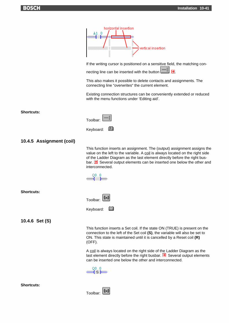
Installation 10-41
If the writing cursor is positioned on a sensitive field, the matching con-
necting line can be inserted with the button . .
This also makes it possible to delete contacts and assignments. Theconnecting line “overwrites“ the current element.
Existing connection structures can be conveniently extended or reducedwith the menu functions under ‘Editing aid’.
Shortcuts:
Toolbar:
Keyboard:
10.4.5 Assignment (coil)
This function inserts an assignment. The (output) assignment assigns thevalue on the left to the variable. A coil is always located on the right sideof the Ladder Diagram as the last element directly before the right bus-bar. Several output elements can be inserted one below the other andinterconnected.
Shortcuts:
Toolbar:
Keyboard:
10.4.6 Set (S)
This function inserts a Set coil. If the state ON (TRUE) is present on theconnection to the left of the Set coil (S), the variable will also be set toON. This state is maintained until it is cancelled by a Reset coil (R)(OFF).
A coil is always located on the right side of the Ladder Diagram as thelast element directly before the right busbar. Several output elementscan be inserted one below the other and interconnected.
Shortcuts:
Toolbar:

Installation10-42
Keyboard:
10.4.7 Reset (R)
This function inserts a Reset coil. If the state ON (TRUE) is present onthe connection to the left of a Reset coil (R), the variable is set ti OFF.This makes it possible to cancel a state created by the Set coil (S).
A coil is always located on the right side of the Ladder Diagram as thelast element directly before the right busbar. Several output elementscan be inserted one below the other and interconnected.
Shortcuts:
Toolbar:
Keyboard:
10.4.8 Timer – Pulse (SI)
The timer is started by a pulse (SI) through a transition from 0 to 1. Thetimer loop name (e.g. 'T1' ) is entered in the input field above the timerelement. Upon confirmation of the input with another input field willappear in which the duration or the timer value and timer value/loop, re-spectively, is entered.
The timer can be stopped via the element ‘Stop (TH)’. The timer statecan be reset with the element ‘Reset (RT)’.
Shortcuts:
Toolbar:
Keyboard:
10.4.9 Timer – Extended Pulse (SV)

Installation 10-43
The timer is started as an extended pulse (SV) through a transition from0 to 1. The timer loop name (e.g. 'T1' ) is entered in the input field abovethe timer element. Upon confirmation of the input with another inputfield will appear in which the duration or the timer value and timervalue/loop, respectively, is entered.
The timer can be stopped via the element ‘Stop (TH)’. The timer statecan be reset with the element ‘Reset (RT)’.
Shortcuts:
Toolbar:
Keyboard:
10.4.10 Timer – Switch-on delay (SE)
The timer is started as a switch-on delay (SE) through a transition from 0to 1. The timer loop name (e.g. 'T1' ) is entered in the input field abovethe timer element. Upon confirmation of the input with another inputfield will appear in which the duration or the timer value and timervalue/loop, respectively, is entered.
The timer can be stopped via the element ‘Stop (TH)’. The timer statecan be reset with the element ‘Reset (RT)’.
Shortcuts:
Toolbar:
Keyboard:
10.4.11 Timer – Remanent switch-on delay (SS)

Installation10-44
The timer is started as a remanent switch-on delay (SS) through a transi-tion from 0 to 1. The timer loop name (e.g. 'T1' ) is entered in the inputfield above the timer element. Upon confirmation of the input with an-other input field will appear in which the duration or the timer value andtimer value/loop, respectively, is entered.
The timer can be stopped via the element ‘Stop (TH)’. The timer statecan be reset with the element ‘Reset (RT)’.
Shortcuts:
Toolbar:
Keyboard:
10.4.12 Timer – Switch-off delay (SA)
The timer is started as a switch-off delay (SA) through a transition from 0to 1. The timer loop name (e.g. 'T1' ) is entered in the input field abovethe timer element. Upon confirmation of the input with another inputfield will appear in which the duration or the timer value and timervalue/loop, respectively, is entered.
The timer can be stopped via the element ‘Stop (TH)’. The timer statecan be reset with the element ‘Reset (RT)’.
Shortcuts:
Toolbar:
Keyboard:

Installation 10-45
10.4.13 Timer – Stop (TH)
This element stops a timer loop. The timer loop name (e.g. 'T1' ) is en-tered in the input field above the timer element.
Please note that the Timer Stop function only makes sense if a timer hasbeen started before.
For examle, if you implemented timer loop T1 as a pulse (SI), you canstop this timer loop through another LD branch.
Shortcuts:
Toolbar:
Keyboard:
10.4.14 Timer – Reset (RT)
This element resets the timer state of a timer loop. The timer loop name(e.g. 'T1' ) is entered in the input field above the timer element.
Shortcuts:
Toolbar:
Keyboard:
10.4.15 Set Counter (SZ)
A counter is loaded with the counter nominal value (word operand). Thecounter name (e.g. 'Z1' ) is entered in the field above the element. Uponconfirmation of the input with another input field will appear in whichthe counter nominal value is entered.
Shortcuts:
Toolbar:
Keyboard:
10.4.16 Up Counter (CU)
The counter counts up when a transition from 0 to 1 occurs. The countername (e.g. 'Z1' ) is entered in the field above the counter element.
The counter state is set to 0 when the count value 0 is reached.

Installation10-46
Shortcuts:
Toolbar:
Keybard:
10.4.17 Down Counter (CD)
The counter counts down when a transition from 0 to 1 occurs. Thecounter name (e.g. 'Z1' ) is entered in the field above the counter ele-ment.
The counter state is set to 0 when the count value 0 is reached.
Shortcuts:
Toolbar:
Keyboard:
10.4.18 Reset Counter (RZ)
Resets a counter. The counter name (e.g. 'Z1' ) is entered in the fieldabove the element. Upon confirmation of the input with another inputfield will appear in which the counter nominal value is entered.
Shortcuts:
Toolbar:
Keyboard:
10.4.19 Jump at RLO = 1 (JPC)
Jump (JPC) within the module if the input condition is met (RLO=1). Thejump destination is specified in the field above the jump element.
The jump flag itself can only be edited if the editing mode is not active(IL).
Shortcuts:
Toolbar:
Keyboard:
10.4.20 Jump at RLO = 0 (JPU)
Jump (JPU) within the module if the input condition is not met (RLO=0).The jump destination is specified in the field above the jump element.
The jump flag itself can only be edited if the editing mode is not active(IL).

Installation 10-47
Shortcuts:
Toolbar:
Keyboard:
10.4.21 Module Call at RLO = 1 (CMC)
Module call (CMC) if the input condition is met (RLO=1). The modulename is specified in the field above the element.
Shortcuts:
Toolbar:
Keyboard:
10.4.22 Module Call at RLO = 0 (CMU)
Module call (CMU) if the input condition is not met (RLO=0). The modulename is specified in the field above the element.
Shortcuts:
Toolbar:
Keyboard:
10.4.23 Call of a second data module at RLO = 1 (MXC)
Calls a data module (MXM) if the input condition is met (RLO=1). Thedata module name is specified in the field above the element.
The call of a second data module is provided if a “first” data module hasalready been called via the function CMC or CMU, respectively.
The access to the data addresses can be specified in IL (editing modedisabled).
Shortcuts:
Toolbar:
Keyboard:

Installation10-48
10.4.24 Call of a second data module at RLO = 0 (MXU)
Calls a data module (MXU) if the input condition is not met (RLO=0). Thedata module name is specified in the field above the element.
The call of a second data module is provided if a “first” data module hasalready been called via the function CMC or CMU, respectively.
The access to the data addresses can be specified in IL (editing modedisabled).
Shortcuts:
Toolbar:
Keyboard:
10.4.25 End of module at RLO = 1 (EMC)
End of module (EMC) if the input condition is met (RLO=1).
Shortcuts:
Toolbar:
Keyboard:
10.4.26 End of module at RLO = 0 (EMU)
End of module (EMU) if the input condition is not met (RLO=0).
Shortcuts:
Toolbar:
Keyboard:
10.4.27 Shift Right
The Shift function offers a convenient way to extend existing connectionstructures.
With each Shift Right operation, the input elements of the LD branch aredisplayed one position to the right. The resulting space at the left busbaris filled with (empty) connections.
Please note that the input elements are “moved out” (= deleted) at theright busbar. If this results inthe unwanted deletion of elements, you canundo the shift operation with the menu function ‘Edit, 'Undo'.
Additional editing options:

Installation 10-49
Shortcuts:
Toolbar:
Keyboard:
10.4.28 Shift Down
The Shift function offers a convenient way to extend existing connectionstructures.
With each Shift Down operation, the input elements of the LD branch aredisplayed one position to the bottom. The resulting space at the top canbe used to insert new elements and connections.
Please note that the input elements are “moved out” (= deleted) at thebottom. If this results inthe unwanted deletion of elements, you can undothe shift operation with the menu function ‘Edit, 'Undo'.
Additional editing options:
Shortcuts:
Toolbar:
Keyboard:
10.4.29 Insert Branch – Before
This function inserts a new LD branch above (before) the current ILline orthe current LD barnch, respectively.
To be able to insert a new branch, you need to exit from the editingmode.
Upon insertion of a new LD branch, the editing mode is called up auto-matically. An LD branch corresponds to a (IL) program branch.
Shortcuts:
Toolbar:
Keyboard: +
10.4.30 Insert Branch – After
This function inserts a new LD branch below (after) the current IL line orthe current LD branch, respectively.
To be able to insert a new branch, you need to exit from the editingmode.

Installation10-50
Upon insertion of a new LD branch, the editing mode is called up auto-matically. An LD branch corresponds to a (IL) program branch.
Shortcuts:
Toolbar:
Keyboard: +
10.4.31 Delete Branch
This function deletes the current LD branch. You can delete the branchdirectly in the editing mode. If you are not in the editing mode, you needto position the writing mark to the LD branch to be deleted.
Shortcuts:
Toolbar:
Keyboard:
10.4.32 Check Branch
This function checks the current LD branch for errors. If no errors arefound, the message “LD branch error-free” will appear.
In addition, the LD branch will be optimized. In this process, all connec-tions between elements are shortened to their optimum length (see illus-tration for example).
Before the optimization:
After the optimization:
Shortcuts:
Toolbar:
Keyboard:

Installation 10-51
10.5 Toolbox Menu – FBD
10.5.1 And (&)
The desired bit operator is entered in the currently highlighted field of theinputs.
The inputs of the function element AND can be edited via the pin ‘Insertinput’, ‘Delete input’ or ‘Negate input’. The writing cursor must be posi-tioned on the line of the input to be edited (see illustration).
The function can be subsequently changed if required. The writing cursormust be positioned inside the function element. If you then select anotherfunction element (OR, EXCLUSIVE-OR), the AND element will be con-verted. The function element can be deleted with the key .
10.5.2 Or (>=1)
The desired bit operator is entered in the currently highlighted field of theinputs.
The inputs of the function element OR can be edited with the pin func-tions ‘Insert input’, ‘Delete input’ or ‘Negate input’. The writing cursormust be positioned on the line of the input to be edited (see illustration).
The function can be subsequently changed if required. The writing cursormust be positioned inside the function element. If you then select anotherfunction element (AND, EXCLUSIVE-OR), the OR element will be con-verted. The function element can be deleted with the key .
10.5.3 Insert FBD pin
This function can be used to insert another input pin (function elementsAND and OR only). The writing cursor must be positioned on the line ofan input (see illustration).
This function can also be activated with the key .
10.5.4 Delete FBD pin
This function can be used to delete an input pin (function elements ANDand OR only). The writing cursor must be positioned on the line of an in-put (see illustration).

Installation10-52
This function can also be activated with the key .
10.5.5 Negate FBD pin
This function can be used to negate a pin or cancel a negation (for func-tion elements AND, OR, flip-flop, timer and counter only). The writingcursor must be positioned on the line of the input (see illustration).
10.5.6 Exclusive Or (=1)
The desired bit operator is entered into the highlighted field of inputs.
Since the function element Exclusive Or (XOR) has always two inputs,these cannot be edited with the pin functions.
The function can be subsequently changed if required. The writing cursormust be positioned inside the function element. If you then select anotherfunction element (AND, OR), the Exclusive Or element will be converted.The function element can be deleted with the key .
10.5.7 SR flip-flop
The function element flip-flop with dominant Set input (SR) has a Set anda Reset input. The desired bit operator is entered into the currently high-lighted field in symbolic or absolute form. The operator of the flip-flopmemory is entered into the field above the function element.
The SR flip-flop is identified by the designation „S1“ at its dominant Setinput.
If the SR flip-flop is used as an output element, the Set input is alwaysconnected with the coupling point.
The function can subsequently be converted into an RS flip-flop if re-quired. The writing cursor must be positioned inside the function element.If you then select the RS flip-flop, the element will be converted. Thefunction element can be deleted with the key .
10.5.8 RS-Flip-Flop
The function element flip-flop with dominant Reset input (RS) has a Setand a Reset input. The desired bit operator is entered into the currentlyhighlighted field in symbolic or absolute form. The operator of the flip-flopmemory is entered into the field above the function element.

Installation 10-53
The RS flip-flop is identified by the designation „R1“ at its dominant Resetinput.
If the RS flip-flop is used as an output element, the Reset input is alwaysconnected with the coupling point.
The function can subsequently be converted into an SR flip-flop if re-quired. The writing cursor must be positioned inside the function element.If you then select the SR flip-flop, the element will be converted. Thefunction element can be deleted with the key .
10.5.9 Timer - Pulse (SP)
Various parameters are entered into the highlighted fields:
A timer is always started by a transition from 0 to 1 at the input (IN: bitoperator). The duration or timer value/loop (PT: word operator) is enteredas an additional input parameter. (ST: Bit operator optional) stops thetimer, and the Reset input (R: Bit operator optional) resets it. The actualtimer value can be read via the output (ET: word operand optional). Theresult of the logic operation (Q: Bit operand) is a function of the behaviorof the selected timer element. The timer loop name is entered into thefield above the timer element.
Not all connections are available with all controllers.
If the timer element is used as an output element, the Timer Start input(IN) is connected with the coupling point.
A timer function can subsequently be converted into another timer func-tion if required. The writing cursor must be positioned inside the functionelement when you select the desired timer function. The timer elementcan be deleted with the key .

Installation10-54
10.5.10 Timer - Extended Pulse (SPE)
Various parameters are entered into the highlighted fields:
The timer is started as an extended pulse (SV) by a transition from 0 to 1at the input (IN: bit operator). The duration or timer value/loop (PT: wordoperator) is entered as an additional input parameter. (ST: Bit operatoroptional) stops the timer, and the Reset input (R: Bit operator optional)resets it. The actual timer value can be read via the output (ET: word op-erand optional). At the output, the extended pulse is available as the re-sult of a logic operation (Q: bit operand). The timer loop name is enteredinto the field above the timer element.
Not all connections are available with all controllers.
If the timer element is used as an output element, the Timer Start input(IN) is connected with the coupling point.
A timer function can subsequently be converted into another timer func-tion if required. The writing cursor must be positioned inside the functionelement when you select the desired timer function. The timer elementcan be deleted with the key .
10.5.11 Timer - Start-up delay (SR)
Various parameters are entered into the highlighted fields:
The timer is started by a transition from 0 to 1 at the input (IN: bit opera-tor). The duration or timer value/loop (PT: word operator) is entered as anadditional input parameter. (ST: Bit operator optional) stops the timer,and the Reset input (R: Bit operator optional) resets it. The actual timervalue can be read via the output (ET: word operand optional). ). At theoutput, the delayed start-up is available as the result of a logic operation(Q: bit operand). The timer loop name is entered into the field above thetimer element.

Installation 10-55
Not all connections are available with all controllers.
If the timer element is used as an output element, the Timer Start input(IN) is connected with the coupling point.
A timer function can subsequently be converted into another timer func-tion if required. The writing cursor must be positioned inside the functionelement when you select the desired timer function. The timer elementcan be deleted with the key .
10.5.12 Timer - Remanent start-up delay (SRE)
Various parameters are entered into the highlighted fields:
The timer is started by a transition from 0 to 1 at the input (IN: bit opera-tor). The duration or timer value/loop (PT: word operator) is entered as anadditional input parameter. (ST: Bit operator optional) stops the timer,and the Reset input (R: Bit operator optional) resets it. The actual timervalue can be read via the output (ET: word operand optional). ). At theoutput, the remanent delayed start-up is available as the result of a logicoperation (Q: bit operand). The timer loop name is entered into the fieldabove the timer element.
Not all connections are available with all controllers.
If the timer element is used as an output element, the Timer Start input(IN) is connected with the coupling point.
A timer function can subsequently be converted into another timer func-tion if required. The writing cursor must be positioned inside the functionelement when you select the desired timer function. The timer elementcan be deleted with the key .

Installation10-56
10.5.13 Timer - Shut-down delay (SF)
Various parameters are entered into the Shut-down delay fields:
The timer is started as a switch-off delay by a transition from 1 to 0 at theinput (IN: bit operator). The duration or timer value/loop (PT: word op-erator) is entered as an additional input parameter. (ST: Bit operator op-tional) stops the timer, and the Reset input (R: Bit operator optional)resets it. The actual timer value can be read via the output (ET: word op-erand optional). ). At the output, the delayed shut-down is available asthe result of a logic operation (Q: bit operand). The timer loop name isentered into the field above the timer element.
Not all connections are available with all controllers.
If the timer element is used as an output element, the Timer Start input(IN) is connected with the coupling point.
A timer function can subsequently be converted into another timer func-tion if required. The writing cursor must be positioned inside the functionelement when you select the desired timer function. The timer elementcan be deleted with the key .
10.5.14 Up Counter (CU)
Various parameters are entered into the highlighted fields:
A counter counts up if a transition from 0 to 1 occurs at the respective in-put (CU: bit operand). A counter is loaded with the nominal counter value(PV: word operand optional) via the Set input (LD: bit operand optional).A counter is reset if the Reset input (R: bit operand optional) is set. Theactual counter value can be read via the output (CV: word operand op-tional). The result of the logic operation (Q: bit operand) is set to 0 whenthe counter reaches 0. The counter name is specified in the field abovethe counter element.

Installation 10-57
Not all connections are available with all controllers.
If the counter element is used as an output element, the input of thecounting edge is connected with the coupling point.
You can subsequently convert the up counter into a down counter if re-quired. Position the writing cursor inside the function element and selectthe down counter function. The counter element can be deleted with thekey .
10.5.15 Down Counter (CD)
Various parameters are entered into the highlighted fields:
A counter counts down if a transition from 0 to 1 occurs at the respectiveinput (CD: bit operand). A counter is loaded with the nominal countervalue (PV: word operand optional) via the Set input (LD: bit operand op-tional). A counter is reset if the Reset input (R: bit operand optional) isset. The actual counter value can be read via the output (CV: word oper-and optional). The result of the logic operation (Q: bit operand) is set to 0when the counter reaches 0. The counter name is specified in the fieldabove the counter element.
Not all connections are available with all controllers.
If the counter element is used as an output element, the input of thecounting edge is connected with the coupling point.
You can subsequently convert the down counter into an up counter if re-quired. Position the writing cursor inside the function element and selectthe up counter function. The counter element can be deleted with the key
.
10.5.16 Up/Down Counter (CU&CD)
Various parameters are entered into the highlighted fields:

Installation10-58
A counter counts up or down if a transition from 0 to 1 occurs at the re-spective input (CU or CD: bit operands). A counter is loaded with thenominal counter value (PV: word operand optional) via the Set input (LD:bit operand optional). A counter is reset if the Reset input (R: bit operandoptional) is set. The actual counter value can be read via the output (CV:word operand optional). The result of the logic operation (Q: bit operand)is set to 0 when the counter reaches 0. The counter name is specified inthe field above the counter element.
Not all connections are available with all controllers.
If the counter element is used as an output element, the upper input ofthe counting edge is connected with the coupling point.
It is not possible to subsequently convert the up/down counter into a dif-ferent counter function. To delete the counter, position the writing cursorinside the function element and press the key .
10.5.17 Comparator - Equal
The word operands to be compared are entered into fields IN1 and IN2. Ifthe two operands are identical (Equal =), the output bit Q is set.
A comparator can subsequently be converted into a different comparisonfunction if required. The writing cursor must be positioned inside thefunction elements when you select the desired comparison. You can de-lete the comparison element with the key .
A comparator cannot be used as an output element.
10.5.18 Comparator - Not equal
The word operands to be compared are entered into fields IN1 and IN2. Ifthe two operands are not equal (Not equal <>), the output bit Q is set.
A comparator can subsequently be converted into a different comparisonfunction if required. The writing cursor must be positioned inside thefunction elements when you select the desired comparison. You can de-lete the comparison element with the key .
A comparator cannot be used as an output element.
10.5.19 Comparator - Greater than

Installation 10-59
The word operands to be compared are entered into fields IN1 and IN2. Ifthe value of the first operand is greater than (>) that of the second, theoutput bit Q is set.
This comparator is not available with some controllers.
A comparator can subsequently be converted into a different comparisonfunction if required. The writing cursor must be positioned inside thefunction elements when you select the desired comparison. You can de-lete the comparison element with the key .
A comparator cannot be used as an output element.
10.5.20 Comparator - Greater than or equal
The word operands to be compared are entered into fields IN1 and IN2. Ifthe value of the first operand is greater than or equal (>=) to that of thesecond, the output bit Q is set.
This comparator is not available with some controllers.
A comparator can subsequently be converted into a different comparisonfunction if required. The writing cursor must be positioned inside thefunction elements when you select the desired comparison. You can de-lete the comparison element with the key .
A comparator cannot be used as an output element.
10.5.21 Comparator - Less than
The word operands to be compared are entered into fields IN1 and IN2. Ifthe value of the first operand is less than (<) that of the second, the out-put bit Q is set.
This comparator is not available with some controllers.
A comparator can subsequently be converted into a different comparisonfunction if required. The writing cursor must be positioned inside thefunction elements when you select the desired comparison. You can de-lete the comparison element with the key .
A comparator cannot be used as an output element.

Installation10-60
10.5.22 Comparator - Less than or equal
The word operands to be compared are entered into fields IN1 and IN2. Ifthe value of the first operand is less than or equal (<=) to that of the sec-ond, the output bit Q is set.
This comparator is not available with some controllers.
A comparator can subsequently be converted into a different comparisonfunction if required. The writing cursor must be positioned inside thefunction elements when you select the desired comparison. You can de-lete the comparison element with the key .
A comparator cannot be used as an output element.
10.5.23 Jump at RLO = 1 (JPC)
Jump (JPC) if the input condition is true (RLO=1). The jump destination isspecified as the operand.
The input condition can subsequently be changed if required. Position thewriting cursor inside the function element and select Jump if RLO=0. Thejump element can be deleted with the key .
10.5.24 Jump at RLO = 0 (JPU)
Jump (JPU) if the input condition is not true (RLO=0). The jump destina-tion is specified as the operand.
The input condition can subsequently be changed if required. Position thewriting cursor inside the function element and select Jump if RLO=1. Thejump element can be deleted with the key .
10.5.25 Module call at RLO = 1 (CMC)
Call module (CMC) if the input condition is true (RLO=1). The destinationmodule is specified as the operand.
The input condition can subsequently be changed if required. Position thewriting cursor inside the function element and select Call module ifRLO=0. The jump element can be deleted with the key .

Installation 10-61
10.5.26 Module call at RLO = 0 (CMCI)
Call module (CMCI) if the input condition is not true (RLO=0). The desti-nation module is specified as the operand.
The input condition can subsequently be changed if required. Position thewriting cursor inside the function element and select Call module ifRLO=1. The jump element can be deleted with the key .
10.5.27 End of module at RLO = 1 (EMC)
End of module (EMC) if the input condition is true (RLO=1).
10.5.28 Output assignment (=)
The assignment relates the result of the logic operations (RLO) with anoperand. As long as the operations are true, the operand remains set.
The bit operand is entered into the input field.

Installation10-62
10.6 Toolbox Menu SFC
10.6.1 Swap out
To structure the sequence more in detail, so-called swap-outs can beproduced. They represent an extract of the sequence. Swap-outs are es-pecially useful for the printing. The swap-out is a graphic tool which doesnot influence the sequence. The swap-out can be cancelled anytime,with the function ‘Swap-in’.
Additionally, branch swap-outs can be produced from a branch of an al-ternative or simultaneous branch. Branch swap-outs are not shown in thetable of contents.
Put the mouse cursor to the element which has to be swapped out, ormark the area which has to be swapped out. For the branch swap-out,you have to put the mouse cursor to the branch which is above the de-sired swap-out branch (see illustration). Next, activate this function, andthe element/the area is relocated and positioned one level lower. A swap-out symbol is produced. In this symbol, the start and finish of the swap-out is indicated.
You can reach the swap-out level with a click on the swap-out symbol.There, you can edit the sequence (extract) further. You change to a lower
level. You can get back to the sequence via the button .
Shortcut:
Symbol bar:

Installation 10-63
10.6.2 Swap in
With this function, you can cancel a swap-out , i.e. all swapped out stepelements are inserted into the original sequence. To cancel a swap-out,you have to place the mouse cursor to the swap-out element.
This operation does not change the sequence. Swap-out and swap-in aregraphic tools for the structure of the sequence.
Shortcut:
Symbol bar:
10.6.3 Insert sequence
In the SFC, you can program several independent sequences.
To insert a sequence, put the mouse cursor in the table of contents onthe field with the index number. Depending on where you put the cursor(up or down), you can insert before or after the current element. You canrealize this with the mouse cursor symbol or , respectively. You canalso delete or move the element.
MADAP sequence
Step marker technique sequence
With a mouse click on ‘Edit ...’, you can reach the correspondent se-quence level.
Shortcuts:
Symbol bar:
Keyboard:
10.6.4 Insert description
In a description field, any text (commentary) can be inserted. The de-scription field is inserted into the table of contents and edited.

Installation10-64
To insert a sequence, put the mouse cursor in the table of contents onthe field with the index number. Depending on where you put the cursor(up or down), you can insert before or after the current element. You canrealize this with the mouse cursor symbol or , respectively. You canalso delete or move the element.
With a mouse click on ‘Edit ...’, you can reach the correspondent se-quence level.
Shortcuts:
Symbol bar:
Keyboard:
Dialog box Description
Headline in the table of contentsHere you can register the text which appears in the description in the ta-ble of contents.
DescriptionHere you can insert any text (commentary).
10.6.5 Transition/Step
With this function, you can insert a step element, consisting of a transitionand a step. With this simple sequence, one step after another is exe-cuted. One step (1) is inactivated, when the transition condition is real-ized (2). That way, the succeeding step (3) is activated (in MADAP, theBEFA condition must be realized for the execution of the step).
Put the mouse cursor on a step to insert a new step element abovethis position. With the programming type step marker technique, you canalso insert on the start step.
If you put the mouse cursor on the connecting line of a transition , astep element is inserted below this position.
You can also delete or move the element at the described positions .
Shortcuts:
Symbol bar:
Keyboard:

Installation 10-65
10.6.6 Simultaneous branch
After the entry (1), all sequences in the branch are executed (2). As soonas all branches are passed through (3) and the transition condition is re-alized (4), it is switched to the succeeding step and all steps within thesimultaneous branch are inactivated.
Put the mouse cursor on a step to insert a simultaneous branchabove this position. With the programming type step marker technique,you can also insert on the start step.
If you put the mouse cursor on the connecting line of a transition , thesimultaneous branch is inserted below this position.
Also, an input transition is inserted immediately before the branch. At thispoint of the transition, the branch can be deleted or moved .
Extend the branch:The inserted simultaneous branch consists in the first place of two branchparts. This branch can be extended with any number of branch parts.You have to put the mouse cursor on a branch insert position . Seealso in the help ‘branch’:
Context help ‘branch’
If simultaneous branches are programmed, Bit 12 (no step-on insame cycle) in parameter 1 of the mode selection, should not be seton 1.
Shortcuts:
Symbol bar:
Keyboard:
10.6.7 Alternative branch
The transitions are checked from the left to the right (1). The first applica-ble transition condition activates the corresponding succeeding step (2).Only the steps in this branch are executed (3).

Installation10-66
Put the mouse cursor on a step to insert an alternative branch abovethis position. With the programming type step marker technique, you canalso insert on the start step.
If you put the mouse cursor on the connecting line of a transition , thealternative branch is inserted below this position.
Also, an input transition is inserted immediately before the branch. At thispoint of the transition, the branch can be deleted or moved .
Extend the branch:The inserted alternative branch consists in the first place of two branchparts. This branch can be extended with any number of branch parts.You have to put the mouse cursor on a branch insert position . Seealso in the help ‘branch’:
Context help ‘branch’
Shortcuts:
Symbol bar:
Keyboard:
10.6.8 Loop
First of all, with the loop, the transition of the succeeding step is checked(1). Then follows the check of the transition condition of the line with anarrow (2). If the return condition is true, it is jumped to the top end of theline with an arrow (3).
Put the mouse cursor on a step to insert a loop above this position.With the programming type step marker technique, you can also insert onthe start step.
If you put the mouse cursor on the connecting line of a transition , theloop is inserted below this position.

Installation 10-67
A body of the loop is inserted with the loop. This body consists of a stepand the return condition. Besides, a transition is inserted above the linewith an arrow. At this position, the loop can be deleted or moved.
Complex loopsAnother possibility of inserting a loop is the marking: If you mark severalsteps (branches and swap-outs, too), the return line is drawn around thewhole marked area .
Nested loopsOf course, the loops can also be nested; i.e. a new loop can be insertedwithin a loop block.
Shortcuts:
Symbol bar:
Keyboard:
10.6.9 Jump
First of all, the transition of the succeeding step is checked (1). Then fol-lows the check of the transition condition of the jump (2). If the returncondition is true, it will jump to the step of the number which is displayedin the jump destination (3).Example: The jump destination includes the entry "4". The jump goes tothe step “xN4” in the current sequence.
Put the mouse cursor on a step to insert a jump above this position.With the programming type step marker technique, you can also insert onthe start step.
If you put the mouse cursor on the connecting line of a transition , thejump is inserted below this position.
Shortcuts:
Symbol bar:
10.6.10 Step action - Non-remanent (=)
With this step action, the feedback variable is set with activating of thestep (On, TRUE), and is set back with inactivating it (Off, FALSE). Thevariable is set as long as the affiliated step is active.
Context help ‘step action’

Installation10-68
With the step action ‘Non remanent’, the same feedback variablecan be used only once in the whole SFC. If you want to access tothe variable more than once, you have to use the step actions ‘Re-manent (S)’ and ‘Reset with priority (R)’.
Shortcut:
Symbol bar: or , respectively
10.6.11 Step action - Reset with priority (R)
With this step action, the feedback variable is set back (Off, FALSE).Even after the inactivation of the step, the variable remains set back.
Context help ‘step action’
Shortcut:
Symbol bar: or , respectively
10.6.12 Step action - Remanent (S)
With this step action, the feedback variable is set (On, TRUE). Even afterthe inactivation of the step, the variable remains set.
Context help ‘step action’
Shortcut:
Symbol bar: or , respectively
10.6.13 Step action - With time limit (SP)
With this step action, the feedback variable (time element) is set with ac-tivating the step (On, TRUE). The given time (in the field below the quali-fier) is set. The variable is set back when the time is over or when thestep is becoming inactive (Off, FALSE).
Context help ‘step action’
Shortcut:
Symbol bar: or , respectively
10.6.14 Step action - With delay (SR)
With this step action, the given time (in the field below the qualifier) is set.The feedback variable (time element) is set (On, TRUE), when the time isover. The variable is set back when the step is becoming inactive (Off,FALSE).
Context help ‘step action’

Installation 10-69
Shortcut:
Symbol bar: or , respectively
10.6.15 Step action - Remanent with time limit (SPE)
With this step action, the feedback variable (time element) is set with ac-tivating the step (On, TRUE). The given time (in the field below the quali-fier) is set. The variable is set back (Off, FALSE) when the time is over,even when the step is not active anymore.
Context help ‘step action’
Shortcut:
Symbol bar: or , respectively
10.6.16 Step action - Remanent with delay (SRE)
With this step action, the given time (in the field below the qualifier) is set.The feedback variable (time element) is set (On, TRUE), when the time isover. The variable is not set back (Off, FALSE) when the step is becom-ing inactive.
Context help ‘step action’
Shortcut:
Symbol bar: or , respectively
10.6.17 Step action - Set counter (SC)
With this step action, a counter is set on the given value (in the field be-low the qualifier). The counter is edited in the field of the feedback vari-able.The counter value can be changed with the step actions RC, CU,and CD.
Context help ‘step action’
Shortcut:
Symbol bar: or , respectively

Installation10-70
10.6.18 Step action - Reset counter (RC)
With this step action, a counter is set back (to the value zero). Thecounter is edited in the field of the feedback variable. The counter valuecan be changed with the step actions SC, CU, and CD.
Context help ‘step action’
Shortcut:
Symbol bar: or , respectively
10.6.19 Step action - Increment counter (CU)
With this step action, a counter is increased (+1). The counter is edited inthe field of the feedback variable.
Context help ‘step action’
Shortcut:
Symbol bar: or , respectively
10.6.20 Step action - Decrement counter (CD)
With this step action, a counter is decreased (-1). The counter is edited inthe field of the feedback variable.
Context help ‘step action’
Shortcut:
Symbol bar: or , respectively
10.6.21 Step action - Module call (CMC)
This step action results in a conditional module call (CMC). The modulecall happens with the activation of the step.
In a dialog box, the module name can be edited.
Context help ‘step action’

Installation 10-71
Shortcut:
Symbol bar: or , respectively
Dialog box Step action module call (CMC)
Here, you can edit the module name for the conditional module call(CMC). You can only choose program modules which are already exis-tent.
10.6.22 Step action - PLC instructions
With this step action you can integrate common PLC instructions.
If you click on the ‘Edit’ field, you reach the PLC level. The inputs canonly be made on this level. You can edit the PLC instructions in the IL,LD, or FBD programming languages.
Edit only the first network on the PLC level. All other networks arenot considered.
With the menu function ‘File’, ‘Back to sequence’, the PLC level is leftand you get back to the sequence. The PLC instructions are saved forevery step in a UAWLxxx.PXO file which is especially made for it (xxx =consecutive number). All inputs are checked and integrated into the se-quence (are not visible).
The instructions are only visible on the PLC level. Instead of this,the step action element „PLC“ is used to indicate the instructions.
Contrary to the function 'Edit', 'Go to PLC instructions for step', the in-structions are executed only when the transition (and BEFA) is realized.
The produced UAWLxxx.PXO file is kept on the harddisk, even if youdelete the corresponding step action 'PLC instructions' (this way, theUndo/Redo function is guaranteed). With the function 'File', 'Create se-quence' you can 'delete all UAWLxxx.PXO’ (option) files which are un-necessary.
Context help ‘step action’
Shortcut:
Symbol bar: or , respectively

Installation10-72
10.6.23 AND transition
The AND transition represents a logical link of bit variables. Put themouse cursor to the entry of a transition to insert the boolean opera-tion.
In the MADAP programming type, the AND transition is applicable to theBEFA elements.
Shortcuts:
Symbol bar:
Keyboard:
10.6.24 OR transition
The OR transition represents a logical link of bit variables. Put the mousecursor to the entry of a transition to insert the boolean operation.
In the MADAP programming type, the OR transition is applicable to theBEFA elements.
Shortcuts:
Symbol bar:
Keyboard:
10.6.25 Negation
With the negation, a transition condition can be inverted. Put the mousecursor to the entry of the transition which has to be negated.
In the MADAP programming type, the negation is also applicable toBEFA elements.
Shortcuts:
Symbol bar:
Keyboard:

Installation 10-73
10.6.26 Comment
A comment field can be inserted in the area between a step and a transi-tion (a transition and a step).
To delete or move a comment field, you have to put the mouse cursor to the line which is to the left of the comment field.
Shortcuts:
Symbol bar:
Keyboard:
10.6.27 Sequence/Step parameters (MADAP only)
Here you can make the presets to the cascade organization moduleKETTE. The global waiting and watchdog time can be adjusted in a dia-log box. Furthermore, PLC instructions can be inserted for a sequence(cascade); so that you can, for example, set the Waiting and the Watch-dog time for a sequence individually.
The chain/step parameters are only relevant for the MADAP program-ming type.
Dialog box Sequence/Step parameters
Parameter for cascade organization moduleHere you can adjust the global Waiting and Watchdog timer. The inputcan be made as a timer (e.g. t#3s) or as a constant. The constant is mul-tiplied with the factor 100ms (e.g. the input 30 is equivalent to the time 30x 100ms = 3s).
PLC instructions for step moduleThis function is now available via the menu 'Edit', 'Go to PLC instructionsfor step'.
Dialog box Sequence/Step parameters CL200
Here you can make the presets to the cascade organization moduleKETTE200 or BTSMADAP. The sequence/step parameters are onlyrelevant for the MADAP programming type. The various registry cardscontain different functions:
General:Here you can adjust the global Waiting and Watchdog timer. Choosethe Number of sequence to which the time setting should correspondto. If you want to set times globally for all chains, activate the option Takeover times of 1st sequence for all sequences. The input can be madeas a timer (e.g. t#3s) or as a constant. The constant is multiplied with thefactor 100ms (e.g. the input 30 is equivalent to the time 30 x 100ms =3s).

Installation10-74
ModuleSelect here the desired function module KETTE200 or BTSMADAP.
You probably have to add the call-up parameters in the registry card'KETTE' or 'BTSMADAP', respectively.
KETTE:If you choose KETTE200 as the function module (must be selected in theregistry card 'General'), then you have to fill-up the call-up parameters:
P0: By activating the Manual diagnosis (1= On, 0= Off) an active step isdiagnosed, independent from an interference message.
P1: Diagnosis branch selection determines, which branch of the se-quence (0= diagnosis in the manual branch, 1= automatic branch) shouldbe diagnosed. A diagnosis, which is activated by a cascade error, will al-ways use the automatic branch.
P2: Edit the Number of sequence, for which the function module is sup-posed to be.
P3: The Sequence number is predetermined.
P4: With Answering of FC you can choose the word operand. Possibleerror or status messages are handed over to the word operand by thecascade organization module.
BTSMADAPIf you choose BTSMADAP200 as the function module (must be selectedin the registry card 'General'), then you have to fill-up the call-up pa-rameters. The fields are already set with default values, which you canchange if necessary.
10.6.28 Copy automatic conditions to the manual branch
Two functions of a sequence can be realized in the MADAP programmingtype: the automatic condition and the manual branch. Whereas the auto-matic branch runs with the defined steps considering the automatic con-ditions, every step in the manual branch is made considering the manualconditions.
During the editing in the automatic branch, the WinSPS copies thestructure of the sequence automatically to the manual branch. Only theinputs in the edit fields of the transition and BEFA conditions are not in-cluded in this copying process.
Activate this function to transmit all entries from the automatic branch tothe manual branch. This is especially useful if you want to realize theinching mode (automatic operation at the touch of a button).

Installation 10-75
In the MADAP programming type, all inserts should be made in theautomatic branch at first. The sequence structure is automaticallytransferred to the manual branch where it can then be changed. Ifyou also need the BEFA- and transition conditions in the manualbranch (inching mode), you can update them with this menu func-tion.
If you principally do not need the manual branch, do not make anychanges there, and also do not execute the copy process of the auto-matic conditions. Hence, you save memory in the controller.
10.6.29 Options
Here, global presets for the sequential function chart can be made. Adialog box appears.
Dialog box Options for sequential function chart
Here, global presets for the sequential function chart can be made.
Relation Symbol/CommentThis preset causes an effect to the representations of the transition, stepaction, and BEFA. Depending on the preset, the width of the representa-tions of symbols (yellow edit field) and symbol comments (white field)changes. As an example, the symbol comment can be totally faded out touse the whole width for the symbols (Symbol 100%, Comment 0%).
Programming typeThere are three ways to program and compile in the SFC editor:
1 MADAP: Especially for the BOSCH control and operate concept
2 MADAP with BEFA=1: Immediate instruction execution (without BEFAcheck)
3 Step marker technique according to IEC 1131-3
Before you start the SFC programming, you have to select the pro-gramming type.
OptionsThe comment fields can include multi-line texts. However, you can alsoactivate the option Single-line comment to get the opposite.
The colored elements are printed in different gray levels when the optionPrint-colored SFC graphic is switched off.
If you activate the option New steps with default value, all edit fields ofthe new steps are set as follows: BEFA with "-LOG0", Step action with "M0.0" and the transition with "-LOG1".

Installation10-76
Activate the option Step modules with xNx labels to use the samesymbolic in the step modules (SCHRKxx.PXO, created with the function'Generate Sequential function chart') as in the sequence itself. This im-proves the readability if you want to check the step modules.
Sequence No. distributionIf you set up a new SFC file or a new sequence in the manual preset, adialog box appears which enables you to distribute chain numbers. Thechain numbers are distributed in ascending order with the preset auto-matic.

Installation 10-77
10.7 Control Menu
This menu contains all functions to handle communications with the con-troller (except for comparison functions; these are contained in the Filemenu):
- Load programs and modules into the controller
- Unload programs and modules from the controller (in preparation)
- Display controller states (Infostatus, reference list)
Additional functions are tailored to the particular features of some specificcontrollers and modules.
The interface test allows the automatic setting of the communication pa-rameters.
10.7.1 Load
This function can be used to load programs or individual modules into thecontroller. All load settings can be made in a dialog box.
Dialog box LoadIn this dialog box, you can specify all relevant parameters for the loadingprocess:
ModuleIf the option current module is selected, only the current module or datamodule file will be loaded into the controller. You should use this optiononly if a complete program has already been loaded into the controllerand you want to ‘exchange’ the respective module.
If you select the option from symbol file (OM, FC, DM), all moduleswhich are listed in the symbol file will be loaded into the controller. Thisprocess loads the entire program.
In case you would like to load the program, but the contents of the datamodules in the controller should not be deleted, then you should choosethe option according to the symbol file from symbol file (OM, FC, with-out DM).
Make sure that all access to data modules is secured.
The option from batch file is used to load all modules which are listed inthe batch file into the controller. This option is particularly suited to loadseveral modules into the controller. The batch file can be selected in theadjacent selector box. The Set-up button can be used to call up anotherdialog box which allows you to edit the selected batch file.

Installation10-78
Controller optionLoading can optionally be either in the Run or Stop mode (with control-ler stop) of the controller. When loading in the Run mode (without con-troller stop) is selected, the modules will be loaded and activatedaccording to their listing sequence in the symbol or batch file, respec-tively.
When loading without controller stop, the module is loaded and im-mediately activated. Therefore, please ensure the proper sequencewhen loading from the symbol or batch file!
This option can be selected for the CL500 multi-processing for the cur-rent control processor or for the entire system.
Check optionWith the option with symbol assignment, all module files will be revisedbefore the loading takes place. This means that symbol changes in thesymbol file will be respected which have been made after the creation ofthe module. We recommend to always activate this option.
The assignment and linking process known from the PROFI soft-ware is not required in the WinSPS software.
The option with parameter check checks the number of parameters forall instructions which contain module calls before the module files areloaded. Module calls without parameters are also checked. This optionshould always be activated.
Loading optionThe loading options can only be selected if the controller option ‘withcontroller stop’ has been selected.
In addition to Reset remanent operand, it is also possible to delete thedata field and the forcing list during loading. It is also possible to loadthe current data field file DFELD.DXD or forcing file FIXIER.FXD into thecontroller. If you only want to load the data field or forcing file withoutmodule files, select loading from batch file and specify an empty batchfile.
Loading is initiated with the OK button.
10.7.2 Unload
This function can be used to unload programs or individual modules fromthe controller. All load settings can be made in a dialog box.
Dialog box UnloadThis function can be used to unload programs or individual modules fromthe controller. Again, they can be set up as a program module file on yourPC. They can be edited and can be loaded anew.

Installation 10-79
Please note that the unloaded modules do not contain symbolic ad-dress operands and comments because they do not exist in thecontroller.
You should only unload modules if there are no current modules on yourPC. Requests guarantee that you do not overwrite existing modules un-intentionally.
You have the following options:
Reference list (OM,FC, DM): The whole program is unloaded from thecontroller.
Reference list (only DM): Only the data modules data modules are un-loaded.
Current module: The module whose name is stated in the presets, isunloaded. Depending on the editor (program or data module), the currentprogram module or data module file will be unloaded from the controller.
From symbol file: All modules which are marked in the symbol file areunloaded.
From batch file: An extract from the symbol file (=batch file) is unloaded.The Set-up button can be used to call up another dialog box which al-lows you to edit the selected batch file.
Additionally, the data field and the forcing list can be unloaded from thecontroller.
10.7.3 Load date and time
This loads the current date and time into the controller.
10.7.4 Load firmware
This function can be used to load a system firmware into the controller.All firmware files in the current ZS directory and in the library directoryare listed in a dialog box.
Dialog box Load system firmwareThe name, the version number and the date of the firmware file areshown. If the file is contained in the library directory, ‘LIB’ is appended tothe filename.
In case you use firmware files from the PROFI Software, the file ex-tensions must be changed from .FBP to .F2P resp. from .FAP to.F7P. WinSPS can only read firmware files entitled .F2P resp. F7P.

Installation10-80
If you use the module ZS201 (or greater), you have to use the „Win-dows qualified“ firmware files.
To load the firmware to the iCL700 you have to switch the control tothe „boot mode“ (knob-setting = C).
Loading is initiated with the OK button. The controller is halted, and theuser program may be deleted.
10.7.5 Compare firmware
This function can be used to compare the system firmware in the con-troller with a firmware file on disk. This allows you to check which firm-ware version resides in the controller. . All firmware files in the current ZSdirectory and in the library directory are listed in a dialog box.
Dialog box Compare firmware fileThe name, the version number and the date of the firmware file areshown. If the file is contained in the library directory, ‘LIB’ is appended tothe filename.
In case you use firmware files from the PROFI Software, the file ex-tensions must be changed from .FBP to .F2P resp. from .FAP to.F7P. WinSPS can only read firmware files entitled .F2P resp. F7P.
The comparison is initiated with the OK button.
Another dialog box will then appear which contains the comparison re-sult:
The name, the version number, the date, the byte length and thechecksum will be displayed for both firmware files. Only when all filesare identical, the system firmware will also be consistent.
You can get more information about the system firmware via the menufunction ‘Control’, ‘Infostatus’.
10.7.6 Save program to EPROM
This function can be used to transfer (save) the current user program inthe PLC memory to the Flash EPROM memory. The controller is haltedduring this process.
For the CL200 this function is not possible in mixed mode (userprogram runs in RAM and in Flash EPROM memory).
After the user program has been saved and programs have subse-quently been reloaded, the contents of both memory areas are dif-ferent!

Installation 10-81
10.7.7 Save program to Memory Card
This function can be used to transfer (save) the current user program inthe PLC memory to the Memory Card (MC). The controller is halted dur-ing this process.
Only the program parts which reside in the RAM memory will besaved; the EPROM memory contents are not saved.
Data modules in the 2nd segment (DM256 to DM511) can not besaved on Memory Card.
10.7.8 Load program from Memory Card
This function can be used to transfer (load) the user program in theMemory Card (MC) to the RAM of the PLC. The controller is halted dur-ing this process.
10.7.9 Save program to System
This function can be used to transfer (save) the current user program inthe PLC memory to the EPROM of the SMNC-module. The controller ishalted during this process.
Please take note of the knob-setting on the SMNC-module.
10.7.10 Load program from System
This function can be used to transfer (load) the user program in theEPROM of the SMNC-module to the RAM of the PLC. The controller ishalted during this process.
10.7.11 Memory dump
This function is only suitable for special debugging purposes using thecontroller.
Dialog box Memory dumpA direct memory dump of the controller can be saved in an ASCII dumpfile. For this purpose, a hexadecimal start address and the length of thedesired dump are specified.
Subsequently, you can call up the text editor with the current dump file.
10.7.12 Delete memory
This function deletes the user program in the PLC memory (RAM).

Installation10-82
10.7.13 Start-up mode
This function is used for the start-up phase of the PLC and determineswhether the program is to be loaded from the RAM memory or from theMemory Card (MC).
10.7.14 Run
This switches the controller into the Run state.
For the CL500, you can specify in another dialog box whether you wantto switch the current control processor or the entire system into Run.
10.7.15 Stop
This switches the controller into the Stop state.
For the CL500, you can specify in another dialog box whether you wantto switch the current control processor or the entire system into Stop.
10.7.16 Infostatus
The Infostatus function collects all available information about the con-nected controller. In addition, a system test about header information andmodule lengths can be made. In case of an error, a detailed error de-scription can be obtained.
A dialog box displays the controller information.
Dialog box InfostatusInfostatus collects all available information about the connected controller(Configuration). In addition, a System Test can check header informa-tion and module lengths. In the case of an error, a detailed error descrip-tion can be obtained (Status Info, Module Stack).
If there are errors in the program sequence, you can use the button Goto which enables you to open and edit the faulty file.
Errors can also be found in library modules. However, only three lines ofthe error position are displayed of the library module.
ConfigurationThis can provide different information, depending on the controller type.The output is cyclically updated.
System TestFor the system test, the reference list is unloaded from the controller andits entries are checked. The result is then displayed.
Diagnostic StackThis collects and displays error and diagnostic states of the controller inchronological order. Date and time of the states are displayed.
Status Info, Module StackThis provides detailed error information in case of an error.

Installation 10-83
Program FlagsThis lists the program flags.
User StackThis displays the user stack.
10.7.17 Reference list
The reference list is a summary of all currently loaded program and datamodules of the controller.
The modules are listed in a dialog box.
Dialog box Reference listThe reference list is a summary of all currently loaded modules, or of theorganizational modules (OM), program modules (FC) or data modules(DM) only.
The module type with module number, the symbolic module name, thehexadecimal start address of the module in the controller, the modulelength in bytes, and the version number listed in the parameter list, aredisplayed. The Attr. column indicates a protected library module .
10.7.18 Interface test
This function checks all available communication interfaces in order tofind the suitable setting on the module. This can be used to determine theinterface parameters COMx, baud rate, parity, data and stop bits or ZATautomatically.
The controller must be switched on and the proper cable (connecting ca-ble K16, K19) must be plugged. If a connection to the controller cannotbe established, check the physical connection between the programmingunit and the PLC.
The interface test can take several minutes. If the matching module isfound at an interface, the parameters will be displayed and the presetsaccepted.
Please ensure that the communication with the controller takesplace with the highest possible baud rate so that the data transmis-sion is not slower than necessary.
10.7.19 System Coordinator (SK Table)
This is used to declare all intelligent modules which operate on the sys-tem bus of the CL500 or CL400.
The SK Table must be edited and loaded into the System CoordinatorSK500 or into the Central Processing Unit ZS400, respectively, before aPLC program is loaded. If intelligent modules are not used in the CL400controller, the SK table need not be edited and loaded.

Installation10-84
The settings are loaded automatically from the file SK.SXK from the sub-directory SK into the dialog box of the SK table. There you can view andedit the settings; in addition, this is the place where the loading of the SKtable into the controller and also the unloading from the controller can bemade.
Dialog box System Coordinator (SK Table)
The table lists all intelligent modules in the order of their module num-bers. In order to add a module to the table or to make changes for alisted module, highlight the desired line in the table.
Editing of the SK table:
ModuleHere you can select the desired module. The modules ZS400 or SK500,respectively, cannot be specified because these modules are alwaysmodule no. 0 and need not be specified explicitly.
It is recommended to use module numbers 1 through 4 for the ZS mod-ules of the CL500.
To delete a module from the SK table, specify ‘None’.
Block addressAfter having selected the module, specify the block address which mustbe consistent with the switch setting on the module. The DIL button canbe used to display an illustration with the DIL switch configuration of themodule.
Please observe the relationships between the permitted block address ofthe module and the number of blocks used in order to avoid addressingconflicts.
Module is in rackIf you want to specify modules in the SK table which will be inserted intothe rack at a later time, disable this option.
If the option is enabled, Yes will be displayed in the column ‘Mod. in rack’in the SK table, otherwise No is displayed.
Number of interrupt modulesThis entry refers to the ZS modules of the CL500 and the ZAT module.
An entry of 1 means that an interrupt input module has been provided.This is not possible for the ZS500.
The entry is displayed in the column ‘IR mod.’ of the SK table.
Synchronization method (not CL400)This entry refers to the ZS modules of the CL500 and the ZAT module.

Installation 10-85
It allows to synchronize the execution of the PLC programs in the abo-vementioned modules at run-time. There are eight synchronization meth-ods which can be enabled via the eight selection options.
Synchronization is not possible for the ZS500.
In the column ‘Synchron. method’ of the SK table, 1 indicates that a syn-chronization is used; otherwise, 0 is displayed.
Remanency error (not CL400)This entry refers to the ZS modules of the CL500 and the ZAT module.
Here you can specify if a Stop is initiated in the case of a data loss (e. g.after removing a module or the memory module) either for the currentmodule only or for the entire system.
The ZS500 module cannot initiate a system Stop (only ZS501, etc.).
The indication Module or System appears in the column ‘Rem. Stop’ ofthe SK table.
AddressThis entry is used for the TCP/IP Address of COM-E Modules.
Peripheral address (not CL400)This entry refers to the ZS modules of the CL500 and the ZAT module.
A relationship exists between the block address and the peripheral startaddress. If the abovementioned modules are selected, the WinSPS soft-ware respects this relationship and displays the matching peripheral ad-dresses. These should only be changed of required.
I/O length, EI/EO lengthThis entry refers to the ZS modules of the CL500 and the ZAT module.
The two entries I/O length and EI/EO length must be identical. The de-fault setting for the useable I/O and EI/EO area is 64 bytes.
While considering various criteria, one of the abovementioned modules(except ZS500) may also be assigned larger or smaller ranges. If therange is enlarged, it should be considered that this reduces the periph-eral range of the next ZS or ZAT module.
Load SK Table:If all module data has been entered, the SK table can be loaded into thecontroller by clicking on the Load button. After the loading of the SK ta-ble, a check is done whether the time in the SK differs to the PC time. Ifthe difference is greater than 10 minutes, a dialog box appears with a re-quest whether the date an time should be loaded into the controller.
The Unload button can be used to unload an SK table from the control-ler.

Installation10-86
Clicking on the OK button will terminate the editing process and save theSK table automatically as file SK.SXK in the subdirectory SK. When thisfunction is called up again, and the last edited state is displayed. In addi-tion, a text file SK.TXT is created in the subdirectory SK and in the cur-rent ZS directory. This file can be printed directly and can thus be usedfor the project documentation.
10.7.20 Load date and time
Loads the current date and time into the controller.
10.7.21 Protocol loader
This function can be used to load protocol files for computer modules intothe controller or deleted in the controller. The files and modules are dis-played in a dialog box.
Dialog box Protocol loader
Protocol filesThis table lists all protocol file which have been found on disk. The proto-col file must be contained in the library directory (also SK directory forCL500). The respective release date, the protocol name and the versionnumber of the protocol are displayed. Moreover, it is indicated for whichcomputer module, with which hardware and firmware version and forwhich channel the file can be loaded.
ModulesThis is a listing of the computer modules which have currently been foundin the controller (entry in the reference list). The block address, the num-ber of blocks used, the hardware and firmware version, the current chan-nel as well as the protocol with version number (if already loaded) aredisplayed.
To load a protocol file into the controller, select the desired protocol fileand the module as well as the desired channel and click on the Loadbutton. It is possible to load a separate protocol for each channel or thesame protocol for both channels. To delete all protocols in a computermodule, select the desired module and click on the Delete button.
The Central Processing Unit (the System Coordinator with CL500) mustbe in the Stop state during loading or deleting. The computer module isnewly initialized after the transfer or the deletion has been completed.This will delete all data which are buffered on the module.
10.7.22 Profibus Projecting
This function can be used to load projecting data into the Profibus mod-ule, read them, compare them and save them. Moreover, it allows you toswitch on/off the Profibus job logging function. The different functions areselected in a dialog box.

Installation 10-87
Dialog box Profibus Projecting
Projecting pathHere you can specify the directory in which the projecting files are stored.The default is the current ZS directory.
Projecting filesThis is a list of all projecting files which are available for the currently se-lected Profibus module. Project name, Date and Time of the files aredisplayed.
ModulesThis is a list of the Profibus modules which are used in the controller. Thedisplay includes the module type, the module number which has beenentered in the SK Table, the station number on the Profibus (can be ed-ited via the Bosch software Profibus Configurator and the DIP switches),the currently loaded projecting files and the Profibus transmission pro-tocol including the version number.
Load/UnloadFor loading or unloading, select the desired modules and the desiredprojecting files and click on the respective button.
The loading process is performed with or without a controller Stop, de-pending on the back-action on the program execution. If a Stop is re-quired, a corresponding prompt will inform you.
CompareThis compares the loaded projecting files with the currently selected filesof the corresponding module. A result is displayed when the check hasbeen completed.
If the job logging function is enabled, channel 0 of the module isblocked for other serial protocols. The module will then output statusmessages over this interface. This allows you to monitor the communica-tion process on a connected terminal or printer.
The job logging function is intended for commissioning purposesonly.
You get a command overview by using "H" (Help) at the control unit ofthe Profibus module.
10.7.23 Load Ethernet projects
This function allows to load projecting files into an Ethernet module(COM-E or CMO2-E module) or to unload them from the module into theprogramming device (PG).

Installation10-88
Projecting pathHere you can specify the directory in which the projecting files (*.ETH)are stored. This directory must already exist and must already containprojecting files. The default is the current controller directory is usedwhich can be modified as required.
Projecting filesThis is a list of all projecting files (*.ETH) which are currently available inthe projecting path. You can select one of these files and transfer it intothe connected Ethernet module by clicking on the Load button.
The list shows the Project name (=filename) as well as the Date andTime when the files have been created.
Projecting files are in ASCIIfile format and can therefore be created andedited with the text editor.
ModulesThis is a list of the currently connected Ethernet modules. It depends onwhich connection is established between the PG and the controller. Forexample, if you use several Ethernet modules on a CL200 and plug theconnecting cable directly into one of these modules, only this singlemodule will be displayed. However, if you connect the connecting cableto the V24 port of the ZE200, all Ethernet modules will bedetected.
The list contains the module type (Bgr type) (e.g. "COM-E" forCL400/500, "COM2-E" for CL200).
The module number corresponds to the consecutive numbering in derSK table for the controllers CL400/500 or the module block address forthe CL200, respectively.
The TCP/IP address of the module is assigned via the SK table.
In addition, the filename of the currently loaded projecting file and thefirmware version number of the module are displayed.
You can load the highlighted projecting file into the selected Ethernetmodule by clicking on the Load button. Any previously loaded projectingfile will be overwritten without prompting.
During the Unloading process, the projecting file is transfered from thehighlighted module into the projecting directory of the PG. If a file with thesame name already exists there, it can be overwritten after a safetyprompt.
The job logging function allows it to record all data which are receivedand sent by the module. This activities can be monitored by connecting aterminal via channel 0 (V24 port) to the Ethernet module. During thismonitoring, no other communication is possible in channel 0.
10.7.24 Load IP address
This function allows to load an IP address into an Ethernet module(COM-E or COM2-E module).

Installation 10-89
The current state is read from the connected module and displayed in alist. The list contains the module type (Mod type) (e. g. "COM-E" forCL400/500, "COM2-E" for CL200). The Mod number corresponds to thesequential numbering in the SK table for the CL400/500 controllers or themodule block address for the CL200, respectively. The TCP/IP addressof the module is assigned via the SK table. The filename of the currentlyloaded projecting file and the firmware version number of the module arealso displayed.
The address can be entered in the edit field New IP address; clicking onthe OK button will write this address into the module.
The change should also be mirrored by a corresponding entry in theSK table (CL400/500 only). This eliminates the risk that incorrect IPaddresses are activated during the next loading of the SK configura-tion.
10.7.25 Load MAP projecting data
This function loads a projecting file into a communications module.
The projecting file is created using the MAP Configurator.
CL400 and CL500:This file must then be copied into the special subdirectory _MAP_MMSEof the current controller directory under the name of R500MAP.CFG. Thedirectory _MAP_MMSE is automatically created by the WinSPS software(from version 2.3) when a new controller CL400 or CL500 is configured. Ifthe directory does not exist, create it (e.g. using the Explorer), and copythe file into this directory.
Example for MAP projecting directory:
C:\Bosch\Project.PRJ\SPS.500\_MAP_MMSE\R500MAP.CFG
CL550:For the CL550 controller, the directory _MAP_MMSE is stored in parallelto the project directory.
Example:
C:\Bosch\Project.PRJ\_MAP_MMSE\COMMAP_11_6.CFG
The directory _MAP_MMSE is automatically created by the WinSPSsoftware when a new controller CL550 is configured. Provided that spe-cific conventions are observed for the assignment of the filename of theprojecting file, it is then possible to use the project configurator of theWinSPS to create an automatic configuration for a group of linked con-trollers.
If all files and directories exist, it must also be ensured that the communi-
cations module is switched "off-line" and that the display shows .

Installation10-90
Upon activation of the load function, a window will appear which logs theloading process. If this window remains empty (black background), this isan indication that
- no proper transfer has been ensured, e.g. because the controller hasnot been switched on
- the connecting cable has not been plugged into the COM4/PG inter-face of the module or into the PG
- the connecting cable is defective
- the module has not been switched "off-line"
- the interface on the PG does not match the interface set in theKERMIT.INI file (see below).
In these cases, an error message will appear after 2-3 minutes. You mayalso cancel the operation by pressing the key even before the errormessage appears. You can close the window by entering Quit orExit and .
The MAP load function uses entries in the configuration file KERMIT.INI.This file is located in the program directory. In this file, the WinSPS soft-ware stores data about the interface, among other information. If prob-lems with these settings occur, call up the menu function ‘Interface test’.
10.7.26 Central Programming
With this function, data for the Central Programming (CP) are displayed.The different functions are selected in a dialog box.
You should look out for the compatibility of the firmware when using themodule COM-E. In the following table, you can see which modules canbe suited to the COM-E:
Module Minimum requestSK500 Firmware Version 205SK510 Firmware Version 205ZS400 Software Version 2.5ZS401 Software Version 2.5
Dialog box Central Programming (Profibus Info)
With this function, PROFIBUS data for the Central Programming (CP) aredisplayed. The various registry cards contain different functions:
GeneralThe position of the Topology (.TOP) and Bus parameter file (.BUS) aredisplayed on the drive. You can change this entry. Both files are set upby the Bosch PROFIBUS configurator software (see paragraph 'CentralProgramming', Preparation - Bus configuration').
The current bus address on the PROFIboard is displayed in the AddressPG field.This address is set by WinSPS automatically (lowest free ad-dress).

Installation 10-91
The Address dest. PLC field displays the bus address which has to beset up on the PROFIBUS module of the current controller.
With the Connecting Test, you can try to set up a connection betweenthe programming unit and the Destination PLC (similar to the interfacetest with a conventional connection).
Life ListHere you can find a list of the available devices which are configurated atthe PROFIBUS:
All bus addresses are listed in the Add. column in ascending order. Thedevice name and/or the controller name follows in the Name column.This name is read from the topology file (.TOP).
The listed controllers do not necessarily have to correspond withthe devices which are actually connected to the bus. You have totake care of the correct addressing for the controllers (DIP switchon the PROFIBUS module).
The Status column either displays ‘- - -‘ if the station is not connected tothe PROFIBUS or switched off, or it displays ‘PASSIVE’ if the station is aPROFIBUS-FMS slave, or it displays the ‘ACTIVE_IN_BUS’ condition ifthe station has been recognized at the PROFIBUS (ready for CP). ThePos. column displays the position of the programming unit (PG) and the(Destination-)PLC.
Further data from the topology file for this device is read when you placethe cursor on an entry in the list. This data is displayed in the Producer,Type, Hardware Release and Software Release fields.
Bus parameterThe data of the current bus parameter file (.BUS) is displayed here.
PROFIboardThe data of the installed PROFIboard is displayed here.
Dialog box Central Programming (TCP/UDP/IP)
With this function, data for the Central Programming (CP) viaTCP/UDP/IP can be changed and displayed. The various registry cardscontain different functions:
IP addressYou have chosen the Internet Protocol TCP/UDP/IP as the interface set-ting in the file presets. A so-called IP-(Target)-Address must be given.Please insert the IP address, e.g. if you want to call up the software PLCPCL via TCP/UDP/IP.

Installation10-92
The settings of the UDP channel options have to be adapted accordingto the capacity of the network. If many devices participate an your localethernet (see also 'Overview'), there might be a high load and it cancause transmitting problems of the net. You can stop this by heighten theRepeat counter and/or the maximum time for request.
With the Connecting Test, you can try to set up a connection betweenthe programming unit and the destination PLC (similar to the interfacetest with a conventional connection).
You have the possibility to protect the PLC against unauthorized writeaccesses by using a password. Please use the button Change pass-word.
You do not have access to the controller any longer when you losethe password!
The password functionality of the module COM-E is available start-ing with version 1.1!
You are asked to put in a password when using the button Login. Afterthat, you get contacted with the TCP/UDP/IP module. This function hasthe advantage of not asking for a password again in the ensuing write-accesses.
OverviewA list of the devices which are connected on the ethernet, occurs here:
The list shows the IP address, the type of device (e.g.. COM-E or PCL)and probably the module name of all found devices. The list can be Ac-tualize via the corresponding button.
Dialog box Change passwordHere, you can put in an individual password to protect the PLC againstunauthorized write accesses. If you already use a password, you canchange it anytime.
You do not have access to the controller any longer when you losethe password!
The password functionality of the module COM-E is available start-ing with version 1.1!
If you did not assign a password, enter the default password"BoschPlcSystems" as the Old Password. You can use any alpha-numerical characters for the New Password. Please note the case shift.The characters are not shown during the input. Instead, every characteris shown as *. You have to repeat the input in the field for the Passwordconfirmation.

Installation 10-93
The password is transferred to the controller with the OK button and it isprobably replaced by the old one.

Installation10-94
10.8 Change Menu
This menu allows you to switch from the Editor
- to the Presets (main menu) or
- to the Monitor.
Another function allows the direct loading of the current program or datamodule with subsequent change into the Monitor.
10.8.1 Monitor
This function can be used to change into the Monitor. The offers the fol-lowing options:
- Testing of programs
- Checking of controller and program states
- Viewing of the I/O state
- Tracing of module calls
- Forcing and manipulation of states
The Monitor requires a connection to the controller. This connection isestablished via a serial port of the computer using connection cable K16,K19 to the controller. The current baud rate is selected in the file presets.You can also make the system perform the settings automatically by se-lecting the menu function ‘Controller’, ‘Interface test’.
If a connection to the controller cannot be established, please check theinterface setting and the physical connection between the programmingunit and the controller.
10.8.2 Load + Monitor
This function activates the loading process for the current program mod-ule or data module file. Only the actual file, but not the whole programwill be loaded into the controller. The controller is not stopped. Subse-quently, the Monitor is called up.
This procedure is the best solution for making program changes with thesystem running and checking these changes afterwards.
Please consider that this loading procedure will append thechanges in the controller; this means that each loading process willreduce the available memory area of the controller. We recommendthat you perform the regular loading procedure (menu ‘Control’,‘Load’) from time to time in order to „clean up“ the program memoryof the PLC“.
The currently used memory area can be viewed in the Monitor via thefunction ‘Control’, ‘Configuration diagram’.
The fastest way to activate this function is by pressing the key .

Installation 10-95
10.8.3 Presets
This function allows you to exit from the Editor and return to the Presets.

Installation10-96
10.9 Help Menu
The WinSPS help provides information about the structure and use of theWinSPS software.
Please push the this button to get more information about using theWinSPS help.
10.9.1 Contents
Calls up the WinSPS help and shows the list of subjects.
Use the index cards of the WinSPS help to find information via the Con-tents, the Index or Search keywords.
Contents:Double-click on a book to display additional subjects. Another double-click will make the subjects disappear.
Double-click on a subject to display the associated help information.
Index:The index works similar to the table of contents while offering the addi-tional option to enter the word you are looking for (or its first letters). Theindex contains a list of major subjects in alphabetical order.
Search:This lists all words which are contained in the WinSPS help. You canenter the work you are looking for (or its first letters) and get a list of allsubjects found which contain this word. You can call up the correspond-ing help subject with a double-click.
The Options button allows you to specify search options.
Please push the this button to get more information about using theWinSPS help.
10.9.2 Software Service
This is how you reach us ... the Bosch Erbach Hotline (+49) 6062 / 78 - 426
For suggestions how we can improve or software, as well as for ques-tions and problems,
you can always contact our telephone hotline. It can be called at normaloffice hours and
is of course available free of charge for registered users of the WinSPSsoftware:

Installation 10-97
Robert Bosch GmbH
Geschäftsbereich Automationstechnik
Herr Michael Tondorf
Abteilung: VTS
Postfach 1162
D-64701 Erbach (Odenwald)
Phone: (+49) 6062 / 78 - 426
Fax: (+49) 6062 / 78 - 662
e-mail: [email protected]
You are also invited to visit our mailbox (+49) 6062 / 7217 via modem.
10.9.3 Info
This function provides information about this version of the WinSPS soft-ware as well as about your existing license.


Monitor 11-1
11 MonitorThe Monitor offers the following options:
- Testing of programs
- Checking of controller and program states
- Viewing of the I/O state
- Tracing of module calls
- Forcing and manipulation of states
11.1 Calling up the Monitor
The Monitor can be called up via the menu function ‘Change’, ‘Monitor’ orthe Monitor button.
In the Editor, the function call ‘Change’, ‘Load + Monitor’ can be used toinitiate the loading of the current program module or data module file witha subsequent call of the Monitor:
Suitable tools are available for each of the monitors Program and DataModule as well as for the combined editors/monitors Operand Field, DataField and Forcing. In addition, the Monitor provides the text editor. Thedesired editor/monitor can be called up via the menu function ‘File’... orvia the six monitor buttons.
The file which has been selected in the Presets is loaded into the corre-sponding editor/monitor. Fixed filenames (DFELD.DXD and FIXIER.FXD)are used for the data field and the forcing list.
Revising existing PROFI projectsExisting files from the PROFI software are automatically converted intothe new WinSPS file format when the monitor is called up (except for li-brary modules!). The program module and symbol files to be edited musthave been created with PROFI software version 3.0 or later. For olderversions, the files need to be converted first using the current version ofthe PROFI software. Additional information about file conversion is con-tained in chapter ‘What you should know before you start’, paragraph‘New project structure’.

Monitor11-2
Language conversion:An instruction list program which has e. g. been written in German (An-weisungsliste, AWL) will automatically be converted into an English In-struction List program (IL) when the English language set is called up(and vice versa).
Simultaneous language conversion and PROFI conversion is notpossible!
11.2 Module check
All modules need to be error-free. The modules are checked before theMonitor is activated. If a switch-over into the Monitor is not possible dueto different module contents, you can use the comparison functions(Editor menu ‘File’, ‘Comparison’) to determine which parts of the pro-gram are not consistent.
11.3 Connection to the PLC
For working in the Monitor mode, a connection to the controller is re-quired. This connection is selected in the file presets. You can also makethe system perform the settings automatically by selecting the menufunction ‘Controller’, ‘Interface test’. If you connected your componentsvia Central Programming, please use the function ‘Control’, ‘Central Pro-gramming’ which includes a special ‘Connecting test’.
If a connection to the controller cannot be established, please check theinterface setting and the physical connection between the programmingunit and the controller.
The cyclic controller access can be seen from the rotating Bosch logo inthe right margin of the toolbar. An active trigger function is displayed bythe continuous change of contrast of the rotating logo.
{bmr mo_bosch.bmp}
The cyclic controller access is interrupted if you switch to the commandlevel (activate the menu bar).
If you switch to another task, the cyclic controller access will continue.This means that data will still be read from the controller and displayedwhile you call up the WinSPS help (as you have done now).
11.4 Multiple calls
The WinSPS software can be started more than once. This allows you toedit several files - which can even belong to different projects - simulta-neously or view them in the Monitor. For example, the first WinSPS proc-ess can control the Monitor display of a program module while thesecond WinSPS process can control the Monitor display of a data mod-ule. In this case, the controller can be accessed over a single controlconnection.

Monitor 11-3
There is the restriction with the Central Programming (CP) that only oneWinSPS may communicate via the CP. All other processes must be con-nected with the controller via the conventional way (serial interface, ZAT).
Multiple calls of a software are often not intended by unexperienced us-ers. If you start the WinSPS software and an active copy already exists inthe memory, a dialog box will appear to notify you of this condition. Youcan then choose whether you want to switch to the already active copy orwhether you want to start the software once more. If desired, this dialogbox can be suppressed with the function switch /d.
11.5 Screen layout
The Monitor screen is subdivided into the areas of the menu and toolbar,network line, work area, Monitor display, symbol display and status line.
In the Monitor, the work area contains the program display on the left-hand side and the Monitor display on the right-hand side; the lattercontains a cyclic display of data and states of the controller. The workarea of the text, operand field, data field and forcing editors allows you tomake inputs for the current file.
The separation line between the program and monitor displays can bemoved. To do this, you can either click directly on the separation line andmove the line up or down while holding down the mouse button, or youcan move the line with the key combination + or + , re-spectively.
The menu and toolbar contain the program functions.
The network line displays information for the current network.
You can suppress the toolbar and the network line with the menu function‘View’, ‘Toolbar’ or ‘Networks’.

Monitor11-4
The symbol display shows all currently used symbols. The separationline between symbol display and input area can be moved so that youcan suppress the symbol display or display it at maximum size. To dothis, you can either click directly on the separation line and move the lineup or down while holding down the mouse button, or you can move theline with the key combination + or + , respectively.
The status line displays current help information. The status line alsocontains the current Line and Column positions of the writing cursor aswell as the program instruction number (PI), the program rung number(RG) and the absolute program address (PAA). The editor mode Insertor Replace is also displayed (can be toggled with the key ). Moreo-ver, there is an indication whether the current file has been opened inRead-only mode (RO).
Operation and keyboard assignment of the Monitors are described inchapter ‘Operating Philosophy’, paragraph ‘Command selection’ pp.
11.6 Program module
11.6.1 Programming language
Program modules can be displayed in one of the programming languagesIL, LD, FBD, SFC and ST.
These programming languages can be activated via the menu function‘View’... or via buttons.
11.6.2 Instruction List (IL)
In the IL representation of the module editor, the left-hand side shows -similar to the module editor - the program instructions and comment linesof the program module file. On the right side of the separation line is theMonitor display, consisting of
- the logic bit operations in the case of bit instructions
- the set flags in the case of word instructions
- the register contents, or the active data modules (see below)

Monitor 11-5
The table below shows how the states are displayed:
not set setInput bit i IOutput bit q QRLO bit 0 1Interrupt ICarry COverflow ONegative NZero Z
The register contents are displayed depending on the selected numericalformat (see below).
For commands that affect timers/counters, the timer or counter state isdisplayed.
If the interrupt mask is changed, the new mask is output in binary form.
Active data modulesAll active modules are displayed at the position of the cursor.
DisplayThe current conditions are displayed dynamically in this mode (Stan-dard).
Edit / LoadYou do not have to leave the monitor to make slight changes in the pro-gram. You can edit individual program lines in the 'Edit' mode and putthem into the controller via the 'Load' function.
It is not possible to load in the 'Display' mode.
Your changes are immediately becoming effective without any re-quest in the controller. Yet, the controller is not stopped. Pleasemake the adequate precautions!
Numerical formatThe menu function ‘View’, ‘Format’ can be used to select different nu-merical formats for the display of data and registers. Moreover, this func-tion allows to choose between Duration and Timer value/Timer loop forthe display of the timer elements. To enhance visibility, all line commentscan be suppressed. Moreover, a trace line can be displayed. The traceline contains a display of the registers of the controller. The contents ofthe registers is updated after each I/O state depending on the position ofthe writing cursor:

Monitor11-6
Scroll Lock / Trace from cursor lineThe Scroll key is used to enable or disable Scroll Lock. With the ScrollLock function enabled, the part of the file is scrolled without changing theposition of the writing cursor. In this way, a specific program rung can bepositioned into the first screen line in order to synchronize this part withthe controller.
If the menu function ‘View’, ‘Trace from cursor line’ is also enabled,Monitor information is only displayed for the lines below the current writ-ing cursor position. Combined with the Scroll Lock function, this allowsyou to limit the Monitor display to specific areas.
11.6.3 Ladder Diagram (LD)
The ladder diagram shows the “flow” in the circuit diagram. Elements andconnections which have no signal (0) are shown as dotted lines (bluecolour); elements and connections which carry a signal (1) are high-lighted (red colour). If the program branch is not executed it will be dis-played grey dotted.
Fixed operands are displayed with the respective conditions 0 or 1 (seeillustration).
11.6.4 Function Block Diagram (FBD)
The function block diagram shows the current state of the network. Con-nections which have no signal (0) are shown as dotted lines; elementsand connections which carry a signal (1) are highlighted (default: red).

Monitor 11-7
11.6.5 Sequential Function Chart (SFC)
On the sequence level , the current condition of the sequence is indi-cated.
Active steps and fulfilled conditions are represented in red. If all condi-tions (transition or command output) are fulfilled in a complex transition orBEFA, the red line is drawn continuously up to the branch of the transi-tion or BEFA condition (see illustration). A negated condition is repre-sented in red when the negated condition is present. Example: Atransition contains the negated condition of I0.0. This entry does not carrya signal. The line for the transition condition is represented in red.

Monitor11-8
With the menu function ‘View’, ‘Show timer and counter values’, a Wait-ing (KWA) and Watchdog timer (KUE) is appended to every step in theprogramming mode MADAP. Furthermore, the current values are outputfor the timer and counter step actions.
Another component, especially for the SFC, is the function ‘Controller’,‘Synchronize to cascade No’. If you activate this function, the monitordisplay is always positioned (scrolled) to the active step.
The displayed operands are read from the controller in consecutiveorder, i. e. they do not necessarily come from the same PLC cycle!
If there is no SFC file displayed in the presets, the SFC programminglanguage can not be activated.
Detailed general information about SFC can be found in theReadSFC.doc file which is located in the WinSPS program directory.
11.7 Data module
In the data module monitor, the left-hand side shows - similar to the datamodule editor - the contents of the data module file. On the right side ofthe separation line, the current data are displayed.
EditingThis mode allows you to edit the data module.
The current line is checked after each character input, and an error IDmay appear in the left margin of the line that contains the error. The cor-responding description for the error ID is displayed in the status line.
DisplayThis mode provides a dynamic display of the current states of the datalines. Non-displayable data (e. g. within Visible strings) are replaced withthe character .
FlagThe initialization values of the data lines can be loaded into the controller(see ‘Control’). For this purpose, they need to be flagged.

Monitor 11-9
If the function ‘Flag’ is activated, all operand lines within the block areaare flagged. If no block area exists, only the current line will be flagged.The flag is displayed by a flag ID in the left margin of the screen.
Each flag can be reset by applying the function ‘Flag’ again to the currentline or the block area.
Flagging is not possible in Display mode.
ControlAll flagged (see ‘Flag’) data lines are loaded into the controller with theinitialization value. Subsequently, all flags are reset (flag ID is deleted).
Controlling is not possible in Display mode.
11.8 Text file
The text editor is also available in the Monitor program. It can be calledup via the menu function ‘File’, ‘Text file’ or via the text editor button.
The text editor can be used to create and edit so-called ASCII text files.This can e. g. be used to view and revise print files.
All ASCII characters which are not provided directly on the keyboard ofthe programming unit can be entered by using the keys of the numerickeypad together with the key ; example:
You want to enter the character { .
The decimal code of the ASCII character is 123. Hold down the key and use the numeric keypad to enter the decimal code 123. Release the
key; the character { is inserted.
11.9 Operand field
In the operand field, you can use the operand field file to
- display,
- edit,
- flag and
- control
any operands on the screen.
Several operands can be displayed at the same time on one screen pagewhich e. g. cannot be displayed simultaneously in the IL Monitor.
You can find a list of the operands in the chapter ‘Data module editor’.

Monitor11-10
Layout of the operand field fileOperand lines (<TAB> = separator or ):
Operand <TAB> Data type <TAB> {Initialization value} <TAB>{comment}
The operand line consists of one symbolic or absolute operand and itsdata type (see paragraph ‘Data types’ in the Editor chapter ‘LanguageSet’). In addition, the operand can be preset via an initialization value(see ‘Flag’ and ‘Control’).
Examples:
I4.0 BOOL 1 ; Comment in the operand field
I4 UINT 2#1111_0000_1010_0110
-Symbol BOOL 0
Data words are addressed by using the absolute or symbolic data mod-ule name and the data address in brackets.
Examples:
DM0[4] WORD 4711
-Data[-Sym] STRING(14) ‘String$r$l’
Timers and counters are defined via the data type TVALUE or CVALUE,respectively.
Examples:
T1 TVALUE
C3 CVALUE
Comment lines:
;{Comment}
(*{Comment}*)

Monitor 11-11
Comment lines are introduced by a semicolon or enclosed in parenthe-ses and asterisks (* and *). It is not possible to use nested comments.
Example: ; Comment line
Example: (* Comment line according to IEC1131-3 *)
EditingThis mode allows you to edit the operand field file.
The current line is checked after each character input, and an error IDmay appear in the left margin of the line that contains the error. The cor-responding description for the error ID is displayed in the status line.
DisplayThis mode provides a dynamic display of the current states of the oper-ands. Non-displayable data (e. g. within Visible strings) are replaced withthe character .
If a forcing exists, this will be indicated.
The displayed operands are read from the controller in consecutiveorder, i. e. they do not necessarily come from the same PLC cycle!
FlagThe initialization values of the operands can be loaded into the controller(see ‘Control’). For this purpose, they need to be flagged.
If the function ‘Flag’ is activated, all operand lines within the block areaare flagged. If no block area exists, only the current line will be flagged.The flag is displayed by a flag ID in the left margin of the screen.
Each flag can be reset by applying the function ‘Flag’ again to the currentline or the block area.
Flagging is not possible in Display mode.
ControlAll flagged (see ‘Flag’) operands are loaded into the controller with theinitialization value. Subsequently, all flags are reset (flag ID is deleted).
Controlling is not possible in Display mode.
During program execution, the state which has been modified in theoperand field is processed instead of the actual state of the con-nected sensors and actuators!
The operands are loaded into the controller in consecutive order, i.e. not necessarily in one PLC cycle! If the loading process extendsover several PLC cycles, a warning will be displayed on the screen!

Monitor11-12
11.10 Data field
In the data field editor, you can use the data field file DFELD.DXD to
- display,
- edit,
- flag and
- control.
the remanent data field on the screen.
Loading, unloading and deleting the data field can also be made in theeditor via the menu function ‘Control’, ‘Load’ and ‘Unload’, respectively.
Layout of the data field fileIn the first line, the data length is specified via the keyword LENGTH. Themaximum length depends on the controller:
- CL200 8192 bytes
- CL350 24576 Byte
- CL400 24576 bytes
- CL500 24576 bytes
- iCL700 32768 bytes
The line with the length specification is followed by the data lines (<TAB>= separator or ):
Data field address <TAB> Data type <TAB> {Initialization value}<TAB> {Comment}
The addressing width of the data type (see paragraph ‘Data types’ in theEditor chapter ‘Language Set’) is used to calculate the next data field ad-dress; e. g.

Monitor 11-13
- BOOL 1 byte
- BYTE 1 byte
- WORD 2 bytes
- INT 2 bytes
- STRING variable
The data field addresses may contain blanks but must be specified in as-cending order. Data types with a data width of 8 bits maximum (BOOL,BYTE, SINT, USINT) can also be set to odd data word addresses. Thedata line can be preset via an initialization value (see ‘Flag’ and ‘Con-trol’). Blanks and non-initialized values are filled with binary zeroes duringloading and controlling.
Example:
LENGTH=12
0 BOOL TRUE ; comment in data field
1 BYTE 255
10 UINT 2#1111_0000_1010_0110
Comment lines:
;{Comment}
(*{Comment}*)
Comment lines are introduced by a semicolon or enclosed in parenthe-ses and asterisks (* and *). It is not possible to use nested comments.
Example: ; Comment line
Example: (* Comment line according to IEC1131-3 *)
EditThis mode allows you to edit the data field file.
The current line is checked after each character input, and an error IDmay appear in the left margin of the line that contains the error. The cor-responding description for the error ID is displayed in the status line.
DisplayThis mode provides a dynamic display of the current data field. Non-displayable characters (e. g. within Visible strings) are replaced with thecharacter .
The displayed data are read from the controller in consecutive or-der, i. e. they do not necessarily come from the same PLC cycle!

Monitor11-14
FlagThe initialization values of the data fields can be loaded into the controller(see ‘Control’). For this purpose, they need to be flagged.
If the function ‘Flag’ is activated, all data lines within the block area areflagged. If no block area exists, only the current line will be flagged. Theflag is displayed by a flag ID in the left margin of the screen.
Each flag can be reset by applying the function ‘Flag’ again to the currentline or the block area.
Flagging is not possible in Display mode.
ControlAll flagged (see ‘Flag’) data lines are loaded into the controller with theinitialization value. Subsequently, all flags are reset (flag IDs are deleted).
Controlling is not possible in Display mode.
The data are loaded into the controller in consecutive order, i. e. notnecessarily in one PLC cycle! If the loading process extends overseveral PLC cycles, a warning will be displayed on the screen!
11.11 Forcing
In the forcing editor, you can edit the forcing file FIXIER.FXD, load it intothe controller (fixed) or unload it from the controller. It is possible to setindividual bits or entire data ranges. This allows you to test the functionsof the PLC program or the modules of the controller in a selective man-ner. On the controller, a forced state is displayed by the indicators.
In order to completely delete a fixation, an empty fixing file can beloaded into the controls.
Loading, unloading and deleting the forcing file can also be made in theeditor via the menu function ‘Control’, ‘Load’ or ‘Unload’.

Monitor 11-15
Layout of the forcing fileThe layout is similar to that of the operand lines in the operand field(<TAB> = separator or ):
Operand <TAB> Data type <TAB> Forcing value <TAB> {Com-ment}
A line consists of a symbolic or absolute operand and its data type (seeparagraph ‘Data types’ in the Editor chapter ‘Language Set’). The oper-and is preset via a forcing value.
The following operands can be used:
- Inputs
- Outputs
- Markers
The selected data type must be suitable for the selected operand. Forexample, bit operands or word operands can be used to force one orseveral operand(s).
Examples:
I4.0 BOOL 1 ; Input 4.0 is set
I2 UINT 2#1111_0000_1010_0110
-Symbol UDINT 16#BADEFADE
In addition, it is possible to „hide“ certain bits from the fixation, so as toexclude them. In order to hide bits from fixation, type ‘x’ instead of thestatus 0 or 1.
Example:
I2 UNIT 2#1x1_xxxx_10xx_0110
In this example, the following entry of the sign 2 is fixed:
I2.0 false
I2.1 true
I2.2 true
I2.3 false
I2.6 false
I2.7 true
I3.5 true
I3.7 true
All other entries are not fixed.

Monitor11-16
Comment lines:
;{Comment}
(*{Comment}*)
Comment lines are introduced by a semicolon or enclosed in parenthe-ses and asterisks (* and *). It is not possible to use nested comments.
Example: ; Comment line
Example: (* Comment line according to IEC1131-3 *)
Load forcing listThe current entries of the forcing file are directly loaded into the control-ler. The forcing becomes active immediately.
The forcing in the controller can be cancelled by loading an empty forcingfile.
During program execution, the forced instead of the actual state ofthe connected sensors and actuators is processed!
Unload forcing listThe current forcing in the controller is loaded into the forcing editor.
In the LD programming language, fixed operands are displayed with therespective conditions 0 or 1 in LD (see illustration).
11.12 Trigger - Tracing program and data access
Trigger program moduleYou can follow-up the command of a program module via the triggerfunction. Triggering makes it easier to use program modules which onlydiffer in their parameters (see diagram).
A certain module call (CM... command, no data modules) can be madeinto a trigger-point, if the function is activated while the cursor is posi-tioned on the desired command. The active trigger function is displayedby the continuous change of contrast of the rotating „Bosch anchor“.
Indirect module commands cannot be triggered.

Monitor 11-17
Triggering is ended via the menu function ‘Controls’, ‘Trigger module call’‘Disable’ or by exiting the monitor program.
You can view all the trigger data via the menu function ‘Controls’, ‘Triggermodule call’ ‘Display’.
Trigger operandsThe triggering of operands is similar to the program tracing.
You can get further information how to set trigger points and additionaloptions in the help to the menu ‘Control’, ‘Trigger Operand address’.

Monitor11-18

Programming languages 12-1
12 Monitor – Menu functions
12.1 File Menu
This menu groups all functions which can be applied to files (e. g. open-ing, saving and insertion of files). In addition, it allows to switch betweenmodule and data module editor and the text, operand field, data field andforcing editors.
12.1.1 Open
This function allows to switch the current file. Only files of the current fi-letype can be opened. For example, if you are in the data module moni-tor, you can only open data module files.
The drive and directory has been specified in the Presets and cannot bechanged. This is also true for the current file type.
You can also enter a new filename in the operand field and text editors.By using the "Read-only" option, you can write protect the file, whichmeans that changes in the file cannot be saved.
A fast change of files can also be made by using the file selector box inthe toolbar.
Dialog box File OpenThis dialog box allows you to switch the current file. The drive and direc-tory are determined by the current Presets in the main menu and cannotbe changed. This is also true for the current file type. This means, if youare e. g. in the data module monitor, you can only open data modulefiles.
When entering the filename, you need not specify the file type.
You can also specify a new filename in the operand field and text editors.
By using the Read-only option you can write protect the file so thatchanges in the file cannot be saved.
The Network button is irrelevant because only the current ZS directorywill be processed.
A fast change of files can also be made by using the file selector box inthe toolbar.
12.1.2 Save
This function saves the currently displayed file.
12.1.3 Save as
This function can be used to save the currently edited file under a differ-ent filename.

Programming languages12-2
Dialog box Save asThis dialog box allows you to save the currently edited file under a differ-ent filename. This also offers the possibility to save the file in a directorywhich is not the current ZS directory, or even under a different drive.
When entering the filename, you need not specify the file type.
12.1.4 Save all
This function saves all opened files in all editors (text, operand field, datafield, and forcing file).
12.1.5 Insert file
This function allows to insert any other file into the currently displayed fileat the writing cursor position.
12.1.6 Change to module monitor
This function is used to change to the current program module file in themodule monitor.
12.1.7 Change to data module monitor
This function is used to change to the current data module file in the datamodule monitor.
12.1.8 Change to text editor
This function is used to change to the current text file in the text editor.
12.1.9 Change to operand field editor
This function is used to change to the current operand field file in the op-erand field editor/monitor.
12.1.10 Change to data field editor
This function is used to change to the current data field file DFELD.DXDin the data field editor/monitor.
12.1.11 Change to forcing editor
This function is used to change to the current forcing file FIXIER.FXD inthe forcing editor/monitor.
12.1.12 File selector
This is a list of the files which have been edited last. If you select a file, itwill be opened for editing, and the corresponding monitor/editor will alsobe called up.
12.1.13 Exit
This can be used to exit from the WinSPS software and return to Win-dows. All modified files can be saved after a request (depending on thesetting of function switch /A).

Programming languages 12-3
12.2 Edit Menu
This menu groups all functions which can be used to edit files.
This includes functions such as:
- Undo/Redo last edit
- Cut, Copy and Paste
- Find.
12.2.1 Undo
This function can be used to undo the previous text editing step. Everyediting which has been cancelled with the "Undo" function can be re-stored with the "Redo“ function.
Example: You have inadvertently deleted a highlighted area (e. g. withthe key ). You can then use the "Undo" function to reinsert the de-leted area into the file. If you subsequently use the "Redo“ function, thehighlighted area will be deleted again.
In all editors (text, operand field, data field and forcing editor), you canundo/redo - depending on the setting of function switch /U - up to 99 con-secutive text editing steps.
12.2.2 Redo
A previous text edit can be cancelled with the "Undo" function. By usingthe "Redo" function, you can restore the original state.
Example: You have inadvertently deleted a highlighted area (e. g. withthe key ). The "Undo" function will reinsert the deleted area into thefile. If you subsequently use the "Redo“ function, the highlighted area willbe deleted again.
In all editors (text, operand field, data field and forcing editor), you canundo/redo - depending on the setting of function switch /U - up to 99 con-secutive text editing steps..
12.2.3 Cut
This function copies the highlighted block area into the clipboard and de-leted (cut out) from the current editor. You can then insert the contents ofthe clipboard at another position or even in a different file. This procedureis the same as the "moving" of texts.
The contents remains stored in the clipboard - and can thus be insertedany number of times - until another highlighted area is saved in the clip-board (the contents will even be retained after you exit from the WinSPSsoftware!).
Move or copy operations can also be performed very easily by using themouse operation Drag & Drop .

Programming languages12-4
12.2.4 Copy
This function copies the highlighted block area into the clipboard You canthen insert the contents of the clipboard at another position or even in adifferent file.
The contents remains stored in the clipboard - and can thus be insertedany number of times - until another highlighted area is saved in the clip-board (the contents will even be retained after you exit from the WinSPSsoftware!).
Move or copy operations can also be performed very easily by using themouse operation Drag & Drop .
12.2.5 Paste
The contents stored in the clipboard is inserted at the current writing cur-sor position.
If an area has been marked before, this area will be overwritten with thecontents of the clipboard.
The contents remains stored in the clipboard - and can thus be insertedany number of times - until another highlighted area is saved in the clip-board.
Move or copy operations can also be performed very easily by using themouse operation Drag & Drop .
12.2.6 Find
This function can be used to find specific pieces of text in the current file.
12.2.7 Find operand address (Single cross reference)
This function allows you to find a specific operand in the current programmodule, operand field or forcing file (e. g. I14.3). The operand address isspecified in a dialog box.
12.2.8 Go to error line
The WinSPS software automatically checks for input errors as soon asthe input is made (edit mode). If errors are detected, an error ID is set inthe first column.
This function allows you to go to the next line which contains an error.The status line displays a description of the error.
12.2.9 Go to PI no.
This function allows you to directly access one of the program instruc-tions (PI) which are numbered consecutively. The number is entered in adialog box.
This function can only be applied to program modules.

Programming languages 12-5
12.2.10 Go to absolute program address
This function allows you to directly access an absolute program addressin the controller (PAA). The address is entered in hexadecimal form in adialog box. The current PAA address is displayed in the status line.
This function can only be applied to program modules.

Programming languages12-6
12.3 View Menu
This menu groups the options for the representation of the monitors. Itallows to switch between the programming languages for program mod-ules
- Instruction List (IL)
- Ladder Diagram (LD)
- Function Block Diagram (FBD)
- Sequential Function Chart (SFC
- Structured Text (ST).
The function switch-over for the editors can be made here.
A base can be specified for the representation of numerical values.Monitor triggering can be selected to be on the first screen line or the cur-rent writing cursor position.
The
- toolbar
- display of the network title
- symbolic display of the operands
can be hidden.
In addition, the layout of the monitor can be customized using differentfonts and color settings.
12.3.1 Instruction List (IL)
This activates the Instruction List programming language. The Instructionlist consists of instructions (commands) in a low-level programming lan-guage.
If you have previously selected a different programming language (LD orFBD), all elements of the previous programming language will be con-verted into the IL programming language.
12.3.2 Ladder Diagram (LD)
The Ladder Diagram programming language is activated. The ladderdiagram is a graphical combination of binary variables (digital logic op-erations). The ladder diagram resembles the circuit diagram of earlierrelay control systems with contacts and reels.
12.3.3 Function Block Diagram (FBD)
The Function Block Diagram programming language is activated. FBD isa graphical combination of different function elements. In FBD, binary(digital) logic operations as well as timer, counter and comparator func-tions and program and module jumps can be displayed.

Programming languages 12-7
If you have selected a different programming language (IL or LD), allelements of the previous programming language will be converted intoFBD function elements. All other function elements which cannot be dis-played will be temporarily displayed in the IL programming language. Inaddition, a corresponding message will appear in the status line.
12.3.4 Sequential Function Chart (SFC)
The Sequential Function Chart programming language chart is activated.SFC makes the graphic programming of a complex task in clear unitspossible. The control flow of these parts can be arranged gradually in se-quential or parallel processes (also known as sequence cascade pro-gramming).
12.3.5 Structured Text (ST)
The programming language Structured Text is activated. ST is a textuallanguage. Contrary to the low-level IL language, ST is a programminglanguage that uses comprehensive constructs to allow a very compactformulation of the programming task. ST offers the advantage that it al-lows a clear program structure. The disadvantage of this language is itslower efficiency. The programs are slower and longer.
To be able to activate this programming language, it is necessary tospecify an ST file in the Presets.
12.3.6 Table of contents
With this function, you can move in the sequential function chart (SFC) tothe table of contents. The table of contents shows the overall view of thesequence structure.
Shortcuts:
Symbol bar:
Keyboard:
12.3.7 One level higher
With this function, you can gradually switch in the sequential functionchart (SFC) one level (or swap-out) back.

Programming languages12-8
Shortcuts:
Symbol bar:
Keyboard:
12.3.8 Sequence title
With this function, the headline of a sequence can be faded out below thetoolbar.
12.3.9 Edit
This is used to switch from ‘Display’ to ‘Edit’ mode. Only if this mode hasbeen selected, you can make inputs in the file and set flags for controlusing initialization values.
Please refer also to paragraphs ‘Instruction list (IL)’, ‘Data module’, ‘Op-erand field’ and ‘Data field’.
12.3.10 Display
This is used to switch from ‘Edit’ to ‘Display’ mode. In this mode, the cur-rent states of the operands or the data field, respectively, in the controllerare displayed.
Please refer also to paragraphs ‘Instruction list (IL)’, ‘Data module’, ‘Op-erand field’ and ‘Data field’.
12.3.11 Control
This is used to control previously flagged lines with the predefined initiali-zation values; this means that the controller will use the initialization val-ues of the flagged operands or data fields, respectively.
Please refer also to paragraphs ‘Data module’, ‘Operand field’ and ‘Datafield’.
12.3.12 Flag
Here you can assign a line or a block with a flag. The initialization valuesof the flagged area can then be loaded into the controller by using thecommand ‘Control’.
Please refer also to paragraphs ‘Data module’, ‘Operand field’ and ‘Datafield’.
12.3.13 Load
Here you can load IL lines which have been altered into the controller.You do not have to leave the monitor to make slight changes in the pro-gram. You can edit individual program lines in the 'Edit' mode and putthem into the controller via the 'Load' function.
It is not possible to load in the 'Display' mode.

Programming languages 12-9
Your changes are immediately becoming effective without any re-quest in the controller. Yet, the controller is not stopped. Pleasemake the adequate precautions!
12.3.14 Format
This is used to specify the display format of numbers and of the trace linein the program module monitor. In addition, all line comments can besuppressed to enhance visibility.
The settings are made in a dialog box.
Dialog box Format settings
Numerical formatThe following formats can be selected for the display of data and regis-ters in the program module monitor:
- decimal signed/unsigned
- binary
- octal
- hexadecimal (sedecimal)
- String = ASCII string
- Visible string
- Octet string
OptionTo enhance visibility, all line comments can be suppressed.
Trace lineThe trace line displays the registers of the controller. The contents of theregisters is updated after every I/O state as a function of the writing cur-sor position.
The registers can be grouped as desired. The trace line is set to the bot-tom of the program module display (see illustration).
Timer formatThis is used to select the display of timer elements either as a duration ora timer value/timer loop.

Programming languages12-10
12.3.15 Symbolic/Absolute
You can select the operand display to be either symbolic or absolute. Ifyou activate the menu item, the operands will be displayed in symbolicform. In the symbol display, the absolute and the symbolic operand aswell as the symbol comment are always displayed.
12.3.16 Network line On/Off
This function enables/disables the network line in the module monitorbelow the toolbar.
If you disable the menu item (Off), all networks will be displayed in con-tiguous form. The network numbers are suppressed, and the network ti-tles are integrated into the program module:
****;Network title
12.3.17 Toolbar On/Off
This function allows you to suppress the toolbar of the Monitor in order toobtain a larger work area.
You will be required to make a temporary exit from the Monitor andswitch to the Presets or the Editor, since the change will only be-come effective after a new call of the Monitor.
The toolbar is scaled automatically. This means that the toolbar alwaysextends across the entire screen at different screen resolutions (e. g. 640x 480, 800 x 600 etc). Automatic scaling can be disabled with the functionswitch /i. This has the effect that, particularly when using high-resolutionmonitors, the entire toolbar is visible even when you work in severalsmaller windows.
12.3.18 Trace from cursor line
If this function is activated, monitor information will only be provided forthe lines below the current current writing cursor position. Combined withthe Scroll Lock function, this allows you to limit the Monitor display tospecific areas.
This function can only be applied to program modules in the IL program-ming language.

Programming languages 12-11
12.3.19 Overview
With this function, you can activate the overview of a sequence. In theoverview, the step elements are marked smaller; the transitions are cutshort to a line. Step actions are not indicated.
12.3.20 Show timer and counter values
With this function, in the programming type MADAP, a Waiting (KWA)and Watchdog time (KUE) is appended to every step. Furthermore, thecurrent values are indicated at the timer and counter step actions.
12.3.21 Font
This function is used to change the character font. A dialog box will ap-pear.
Please consider that a subsequent font change can affect the layoutsince the text is shifted and some characters may not be display-able. These shifts can occur especially if proportional fonts areused.
The default font for the WinSPS software is ‘Courier, Regular, 9’.
12.3.22 Color
This is used to make the color selections for Editor and Monitor. The pa-rameters are specified in a dialog box.
Programming languages12-12
12.4 Control Menu
This menu contains functions to handle communications with the con-troller:
- Run/Stop switch-over
- Disable/enable outputs
- Display controller states (Infostatus, configuration diagram, referencelist)
- Loading/unloading of the forcing file
- Module change (call level)
12.4.1 Run
This command switches the controller into the Run state.
For the CL500, you can select in another dialog box whether you want toswitch the current control processor or the entire system into Run.
12.4.2 Stop
This command switches the controller into the Stop state.
For the CL500, you can select in another dialog box whether you want toswitch the current control processor or the entire system into Stop.
12.4.3 Enable outputs
This function is used to enable any previously disabled outputs so thatthey can be addressed again by the PLC program.
Please note that a slide switch on the central processing unit (ZS)does also affect the disabling of the outputs. The current state canbe viewed via the Infostatus function.
12.4.4 Disable outputs
This function can be used to reset all controller outputs to 0 and holdthem in this state. The outputs cannot be addressed by the PLC program.
Please note that a slide switch on the central processing unit (ZS)does also affect the disabling of the outputs. The current state canbe viewed via the Infostatus function.
12.4.5 Change module one level Down (Plus)
If the writing cursor is in a line which contains a module call, this functioncan be used to switch to the associated module.
This function can also be activated via the key .

Programming languages 12-13
12.4.6 Change module one level Up (Minus)
This function allows you to return to the calling module if a modulechange has been made via the Plus function.
This function can also be activated via the key .
12.4.7 Infostatus
A dialog box displays controller information.
Dialog box InfostatusInfostatus collects all available information about the connected controller(Configuration). In addition, a System Test can check header informa-tion and module lengths. In the case of an error, a detailed error descrip-tion can be obtained (Status Info, Module Stack).
ConfigurationThis can provide different information, depending on the controller type.The output is cyclically updated.
System TestFor the system test, the reference list is unloaded from the controller andits entries are checked. The result is then displayed.
Diagnostic StackThis collects and displays error and diagnostic states of the controller inchronological order. Date and time of the states are displayed.
Status Info, Module StackThis provides detailed error information in case of an error.
Program FlagsThis lists the program flags.
User StackThis displays the user stack.
12.4.8 Configuration diagram
A dialog box contains a graphic display of the current memory configura-tion of the controller.
Dialog box Memory configuration (Configuration diagram)
This is a graphic representation of the PLC memory area. The memoryarea which is used by the reference list and the PLC program is dis-played. It also informs you about the inserted I/O modules. They are il-lustrated bytewise with colours.

Programming languages12-14
To check the I/O configuration, the corresponding entries must be avail-able in the organization module OM2.PXO. Conflicts show a multipleplacement of I/O modules (e.g. overlapping with decentral I/O) or a minorplacement (e.g. wrong DIP switch selection on the module).
12.4.9 Reference list
The reference list is a summary of all currently loaded program and datamodules of the controller.
The modules are listed in a dialog box.
Dialog box Reference listThe reference list is a summary of all currently loaded modules, or of theorganizational modules (OM), program modules (FC) or data modules(DM) only.
The module type with module number, the symbolic module name, thehexadecimal start address of the module in the controller, the modulelength in bytes, and the version number listed in the parameter list, aredisplayed. The Attr. column indicates a protected module.
12.4.10 Load forcing file
This loads the current entries in the Forcing file directly into the controller.The Forcing becomes effective immediately. The forcing in the controllercan be cancelled by loading an empty forcing file.
During program execution, the forced instead of the actual state ofthe connected sensors and actuators is processed!
12.4.11 Unload forcing file
This loads the current forcing from the controller into the forcing editor.
12.4.12 Trigger activate program module
This function allows you to carry out (trigger) the command of a programmodule. Triggering makes it easier to activate otherwise identical pro-gram modules with differing parameters (see diagram).
A certain module call (CM... command, no data modules) can be madeinto a trigger-point, if the function is activated while the cursor is posi-tioned on the desired command. The active trigger function is displayedby the continuous change of contrast of the rotating „Bosch anchor“.
Afterwards, you can change to this module using the function ‘Control’,‘Change module one level down +’. The module is processed, if the fol-lowing information ‘Trigger module in progress’ appears in the status bar.

Programming languages 12-15
Indirect module commands cannot be triggered.
Triggering is ended via the menu function ‘Controls’, ‘Trigger module call’‘Disable’ or by exiting the monitor program.
You can view all the trigger data via the menu function ‘Controls’, ‘Triggermodule call’ ‘Display’.
12.4.13 Trigger deactivate program module
This function deactivates triggering. Triggering is also ended upon leav-ing the monitor program.
12.4.14 Trigger display program module
This function displays trigger data.
The display shows the calling Source module, the precise position of thetrigger point, the program instruction number (PI), and the Destinationmodule, shows which module can be traced.
12.4.15 Trigger Operand Address
With this function, you can watch and display the access to an absoluteword address. Trigger Operands is only possible with innovative control-lers such as CL350, CL400, CL500, CL550 or PCL. According to thecontroller, the operands E, A, M, SM, T, Z, S, DP, DF, and DBx[y] arevalid. For the triggering of data words, the file module name is put in asan operand and the data word address in square brackets.
For an additional limit you can edit if a reading and/or writing accessshould be observed. Besides, you can trigger the number of accesses,i.e. the operand will supply the result 'Trigger address found' in thestatus not until the corresponding number of accesses have been madeon this operand.
As a result, the program module with the affiliated absolute programaddress (PAA) where the access was made, is indicated.
You can finish the triggering with the "Go to" button and switch directlyto the appropriate position in the program module.
12.4.16 Synchronize to cascade no.
If you activate this function, the monitor display is always positioned(scrolled) to the active step of the sequence.
In a dialog box you can choose which sequence cascade shall be „fol-lowed“.
Shortcut:
Symbol bar:

Programming languages12-16
12.4.17 Central Programming
With this function, PROFIBUS data for the Central Programming (CP) aredisplayed. The different functions are selected in a dialog box.

Programming languages 12-17
12.5 Change Menu
This menu allows you to switch from the Monitor
- to the Presets (main menu) or
- to the Editor.
12.5.1 Editor
This function allows you to switch into the Editor. The Editor has the fol-lowing functions:
12.5.2 Presets
This function can be used to exit from the Monitor and to return to thePresets.

Programming languages12-18

Communications and networked systems 13-1
13 Communications and networked systemsThe controllers offer various options to implement networked systems:
- The central programming comprises the centralized monitoring, opera-tion and control of a system and its individual components (controllers)via Ethernet TCP/IP or PROFIBUS FMS.
- The CL550 allows communications between controllers, control ter-minals and PCs via Ethernet TCP/IP.
- Remote access via communications modules in the controllers or di-rect PC communications with the PCL controller.
The following section contains a detailed description of these possibilitiesand of the configuration of networked systems.
13.1 Project configurator
13.1.1 System-wide communications
The CL550 allows communications between external controllers, controlterminals and PCs via Ethernet TCP/IP. This allows the exchange of pro-cess and application data. For communications at the control level, theEthernet TCP/IP port is already provided on-board. Optional plug-inmodules with LAN protocols (e. g. COMMAP) are available for integrationinto higher-level production host systems.
Example of a networked subsystem
The WinSPS project configurator is used to define and edit networkedsystems in order to create a network of controllers that can communicatewith each other.

Communications and networked systems13-2
A system is a network of several production systems, the so-called sub-systems. These subsystems comprise a number of racks that consist ofthe ZS550 controllers and the system modules with TCP/IP communica-tions capabilities (e. g. COMMAP). For the purpose of processing in theproject configurator, this hierarchical organization results in a tree struc-ture.
A key function of the project configuration is the assignment and controlof the IP addresses and the setting of the individual Ethernet parameters.This creates a unique assignment of the individual controllers and com-munications modules within the system.
Password-based security features allow to securely access the systemand its components.
13.1.2 Program call
The project configurator is an editing program that is called up throughthe project presets of the WinSPS. A prerequisite for the call of the proj-ect configurator is the use of a type CL550 controller. The project con-figurator can only be started for these controllers.
You will need a special license for the project configurator. The projectconfigurator cannot be called up unless a valid license is available. Li-cense management is called up via the WinSPS project presets. A li-cense for “Project configurator” and für the “CL550” controller must beavailable. You can obtain further information about the license throughthe Help feature of the WinSPS project presets.
When the project configurator is started, the WinSPS software will auto-matically create a directory for all project files. You can obtain further in-formation about this topic in the section “What you should know beforeyou start, Files of the WinSPS software”:

Communications and networked systems 13-3
13.1.3 Creating and editing a project
The configuration file contains all CL550 racks with the associated sys-tem modules of a system or subsystem. The input mode is initiated with
the function “Create new configuration file” . You can either acceptthe configuration data on-line if you have already built a networked sys-tem and connected it to the PC, or you can initiate the automatic creationof the project structure from the directory structure. You can find detailedinformationen about these options in the paragraph “Creating a configu-ration file”.
During the subsequent editing process, you can e. g. create a “subsys-tem”. This can be merged with other subsystems to form a completesystem later on. This procedure allows the step-by-step commissioning ofindividual segments of a system.
The editing area lists the system as a hierarchical tree structure. This al-lows to classify the system into subsystems, racks and system modules.You can open or close the next lower structure by using the (+) or (-)buttons.
Subsystems can only be edited if the option “With subsystem structure”has been enabled during the creation of a new configuration file. For rea-sons of compatibility, the level and the symbol of the subsystem isalso displayed for files for which the “Subsystem structure” option is notspecified.
The “Insert element” function inserts a new component below thecurrent position. The current position will determine the type of element tobe inserted (see table).
Current position Inserted elementSystem SubsystemSubsystem RackRack System module

Communications and networked systems13-4
Most editing fields can be edited directly. For example, it is possible toenter the desired IP address for a system module into the editing field.
The “Delete element” function deletes the selected component.
13.1.4 Control tree - Configuring the system
The editing area contains essential data in tabular form that are importantfor system projecting.
Control treeThis column contains the elements of the system in a hierarchical treestructure, consisting of:
- (Entire) System
- Subsystems
- Racks (card cages)
- System modules (ZS550 and COMMAP)
The name of the system is derived from the configuration file name andcannot be changed.
Subsystems can be assigned any name if the “With subsystem structure”option has been enabled during the creation of the file.
The rack number (Rack ID) can be in the range 1 through 99. It must beunique within the entire network and identical with the rack numberswitch setting on the controller. You have two possibilities:
1) If the CL550 is run without CON550 module, the Rack ID is setwith the DIP switch in the GG4/9 rack next to the power supply slot.
2) If the CON550 is used, the rack address is set on the CON550.
The rack slot number (Rack Slot ID) designates the positioning of a sys-tem module within a rack. it is defined by the slot and can be selectedfrom 1 through 6 for the GG4/9 rack. Numbering is from left to right,starting with slot 1 next to the power supply.
It is possible to select individual elements (see illustration above). Thisallows it e. g. to load only the selected elements.

Communications and networked systems 13-5
TypeThis column designates the element type:
GG4/9 Rack, card cage
ZS550 Central Processing Unit of the CL550
COMMAP Communications-enabled system module
NameThe name entry is optional. Usually, this will be the controller name of theassociated WinSPS project. If the configuration file is automatically cre-ated based on the directory structure, the controller name will appear inthese fields. You can find further information about this process in theparagraph “File menu, Create configuration file”.
The name is stored in the associated system module during the loadingprocess.
IP Address Front SideThis is used to edit the IP addresses of the so-called Front Side of theZS550 system module. Only addresses within the defined IP addressrange are accepted, see function “Presets”. You can obtain further information about the Front Side in the paragraph“Front Side and Back Side”.
IP Address Back SideEditing of the Back Side address occurs in the same manner as in the“Front Side” column. The Back Side can also be used to address theCOMMAP module. You can obtain further information about the BackSide in the paragraph “Front Side and Back Side”.
The subnets must be different for Front and Back Side.
StatusThis column is provided to display short status messages and cannot beedited. The detailed descriptions of these message are displayed whenyou place the cursor on the field in the status line.
CommentAny comment text can be entered here. it will be stored in the configura-tion file and also loaded into the hardware.
13.1.5 Front Side and Back Side
The ZS550 has two Ethernet ports; one of them is wired on the frontpanel (Front Side), the other on the backplane (Back Side).
The Back Side port is used for communications with other system mod-ules within the same rack. Backplane communications requires theCON550 modules. The CON550 module with switch functionality is usedto interconnect the Back Side Ethernet ports of the system modules.They form a local network within the same rack. The CON550 extendsthe Back Side to the outside so that several controllers can be net-worked.

Communications and networked systems13-6
The Front Side port is used to handle communications e.g. with the pro-jecting PC or with control terminals.
The communications capabilities of the Front Side communicationschannel is limited to the resources of the associated ZS550, i. e. there isno connection to the Back Side communications channel.
Because communications at the application end is handled via theFront Side port of the COMMAP system module, loading of the con-figuration file into the COMMAP can only occur via the Back Sideport.
You can obtain information about the loading of MAP projecting data inthe corresponding section of the WinSPS help.
The subnets must be different for Front and Back Side! However,the same subnet mask must be specified for both ports!
TIP
The capability of the CL550 to run two independent Ethernet communi-cations systems on the same controller offers specific advantages forsystem design. For example, by dividing the Front Side into one subnetand the Back Side into another subnet, application data (Front Side) thatare exchanged between a ZS550 and a control terminal will not affect thesecure data exchange within the rack or the controller network (BackSide).
TIP
If you want to implement applications across several controllers, such ascentral programming, OPC client/server applications, etc. in your system,it is recommended to use the Back Side port.
13.1.6 IP addressing
A key function of the project configuration is the assignment and controlof the IP addresses and the setting of the individual Ethernet parameters.This creates a unique assignment of the individual controllers and com-munications modules within the system. Each network card in the com-puter and in the controllers has its own IP address. This address is alsoassociated with a subnet mask.
An IP address is 32 bits long and is specified in the form of four numeri-cal groups that are separated by dots. Each numerical group is in therange 0 through 255. This representation is the so-called octet notation.
Example: 121.2.64.229

Communications and networked systems 13-7
An IP address is also subdivided into a net (Net ID) and node address(Host ID). The net address designates the corresponding subnet. Thenode address is used to address a station within the subnet. This subnetis specified by the subnet mask.
There are 5 so-called address classes, depending on the size of the net:
Class Description Address rangeClass A 1 bytes net and 3 bytes node address 1.x.x.x - 126.x.x.xClass B 2 bytes net and 2 bytes node address 128.0.x.x - 191.255.x.xClass C 3 bytes net and 1 byte node address 192.0.0.x - 223.255.255.xClass D Multicast addresses (special addresses)Class E Reserved
IP addresses within the address range of classes A, B, and C can beused to address the communications modules.
There are also several reserved special addresses that should not de-signed to address the communications modules:
Loopback addresses 127.x.x.xMulticast addresses 224.0.x.xBroadcast address 255.255.255.255
In addition to the IP address, individual Ethernet parameters can bespecified to tailor the system or parts of it for special communicationsneeds.
The address range can also be limited individually.
The local network card must also have an IP address in the same subnetif the PC is to be directly integrated into the subnet. This is an examplefor the setting of the network card:
13.1.7 Subnet mask
The subnet mask defines the size of a net. The subnet mask must beidentical for all stations within a net; otherwise these stations cannot rec-ognize that they belong to the same net.
The subnets must be different for Front and Back Side! However,the same subnet mask must be specified for both ports
The address which is used to reach each communications-enabled com-ponent within a net is comprised of an IP target address and the subnetmask that are ANDed and form the locally valid subnet address. A packetis switched within the local net only if this AND operation supplies the lo-cal subnet address. If the result is different, the packet is sent to the sub-net router (if used, see below ).
The subnet mask is defined with the menu function “Ethernet, Edit pa-rameters”.

Communications and networked systems13-8
Example:The following configuration shows different address ranges for Front and Back-Side.
The subnet mask must be matched to the address ranges (or vice versa). The following examples use two set-tings of the subnet mask. In these examples, the ZS550 module with Rack Slot ID 1 is used as the target ad-dress.
Example 1: Octet notation Binary
Subnet mask 255.255.0.0 11111111.11111111.00000000.00000000
Target address Front Side 121.1.1.1 01111001.00000001.00000001.00000001Result of AND operation 121.1.0.0 01111001.00000001.00000000.00000000
Target address Back Side 121.1.100.1 01111001.00000001.01100100.00000001Result of AND operation 121.1.0.0 01111001.00000001.00000000.00000000
The subnet mask 255.255.0.0 is not suitable for this example because the result of the AND operation does notallow the distinction between Front and Back Side. Front and Back Side of the module would be in the samesubnet and could not be uniquely addressed.
Example 2: Octet notation Binary
Subnet mask 255.255.192.0 11111111.11111111.11000000.00000000
Target address Front Side 121.1.1.1 01111001.00000001.00000001.00000001Result of AND operation 121.1.0.0 01111001.00000001.00000000.00000000
Target address Back Side 121.1.100.1 01111001.00000001.01100100.00000001Result of AND operation 121.1.64.0 01111001.00000001.01000000.00000000
Using the subnet mask 255.255.192.0, the AND operation of Front and Back Side delivers different results.Front and Back Side are not in the same subnet. This allows a unique addressing.The selected subnet mask yields the following addressable ranges:Front Side port: 121.1.[0..63].xBack Side port: 121.1.[64..255].y
Subnet router:Gateways or routers are used for communications across net bounda-ries. This allows e.g. remote maintenance and remote diagnostics. If youuse such a component, its address that may be used to reroute da-tagrams must be in the same subnet as the automation components thatuse this gateway/router.
The following example shows a system that is connected to a gateway orrouter via the Back Side port. All IP addresses must be in the same sub-net. The component contains the address “121.1.100.100”.

Communications and networked systems 13-9
You can find further information about the integration of gateways/routersin the paragraph “Ethernet, Edit parameters”.
The local network card must also have an IP address in the same subnetif the PC is to be directly integrated into the subnet. This is an examplefor setting the network card:
13.1.8 Ethernet settings
To tailor the system or parts of it to specific communications needs, it ispossible to specify individual Ethernet parameters. With a new system,the following default parameters are assigned that can subsequently bechanged:
Parameter DefaultSubnet mask (system-wide) 255.255.0.0IP address of the default gateway 0.0.0.0Retransmisssion Timer 200 msRetransmisssion Counter 8IP Lifetime 60 sTransfer rate and transfer type Auto negotiation
It is also possible to read and display these parameters directly from theconnected system modules.
The help function for the menu function “ Ethernet, Edit parameters”contains a detailed explanation of the different options for setting theEthernet parameters.
13.1.9 Checking and enabling a system configuration
After creating the system configuration, the entries should be checked for
errors using the function “Check configuration table” and then saved
. The check verifies the system module number within a rack as wellas all Front and Back Side IP addresses and the rack numbers of the en-tire system. The function “Presets” allows the selection of additionalcheck options.
The function “Load configuration table” can be used to load the entries
into the system .

Communications and networked systems13-10
13.1.10 File menu – Create configuration file
This function can be used to create a new configuration file. The configu-ration file contains all CL550 racks with the associated system modulesof a system or subsystem.
The Name input field is used to enter the filename. This name will also beused as the name of the system in the control tree.
The option With subsystem structure alllows to subdivide your systeminto several subsystems. For example, you can create a subsystem whenyou edit the file. You can then merge this subsystem with other subsys-tems to form a complete system. This process allows the step-typ-stepcommissioning of individual segments of a system. If you chose the op-tion “With subsystem structure”, you must also edit the fields in the “Sub-system” area (see below ).
Once you have decided to use the option with or without subsystemstructure, you cannot change this setting for the current file lateron! Please also observe that, when merging several subsystems, allfiles must have the same option! It is not possible to mix files withdifferent options.
TIP
Always create structured systems with subsystems! This gives you thenecessary flexibility in terms of future expansions of your system topol-ogy.
You can accept the configuration data on-line if you already estab-lished a networked system and connected it to the PC. The configurationis read from the system and loaded into the control tree. In this process,the network is scanned, and only the modules that can be found in thenetwork are included. Comments and individual Ethernet parameters arealso read from the system and displayed. This procedure has the sameeffect as the “Scan configuration” function.
You may also choose to create the project structure automatically fromthe directory structure. In this process, the names of the subsystems –provided the option “With subsystem structure” has been enabled – andthe racks and system modules are derived from the names of the subdi-rectories. The search is made in the current project path as defined in theWinSPS presets and from there in all subdirectories. Rules for the as-signment of directory and file names ensure that the project configurator“knows” which files to load. The following project example contains adetailed description of these rules
TIP
Please select appropriate names for directories and files already whencreating PLC projects in WinSPS.

Communications and networked systems 13-11
The Rack range is used to delimit the rack numbers (Rack IDs). Thedefault range is 1 to 99. The values can be subsequently changed withthe menu function “Presets”.
It is possible to specify a Password in order to protect the entire systemfrom unauthorized access. This system protection can be specified whena new configuration file is created or at any later time with the menufunction “Project protection, Change system password”. The systemprotection can be disabled by leaving the input field “New password”empty.
If you want to subdivide your configuration into Subsystems (see above), you must specify at least one subsystem in this field. This is done
with the following steps:
1) Enter the Name of the subsystem in the input field.
2) Using the corresponding input options, specify how many Racks,controllers (ZS = Central Processing Unit) and COMMAP systemmodules shall be created for this subsystem.
3) If you want to specify a start address for the first Rack ID, this canbe done in the input field Start number.
4) Load the subsystem into the configuration. This will insert theinputs made in steps 1) through 3) into the subsystem.
You can repeat these steps for additional subsystems. This allows tostructure a large system with subsystems already during the creation ofthe configuration file. The configuration can then be further edited in thecontrol tree.
Click on the OK button to create the configuration file.
Shortkeys:
Toolbar:
13.1.11 File menu – Open configuration file
This function is used to open an existing configuration file for editing. Thefiles are contained in the subdirectory named “_Config_CL550” whichfollows immediately after the project path that is specified by the WinSPSsoftware. When entering the file name, the predefined file type extension“.cfg” can be omitted.
Shortcuts:
Toolbar:
13.1.12 File menu – Save configuration file
This function is used to save the currently displayed configuration file.
Shortcuts:
Toolbar:

Communications and networked systems13-12
13.1.13 File menu – Save configuration file as
This dialog box allows to save the currently edited configuration file undera different filename. You can also save the file in another directory thanthe predefined “_Config_CL550” directory or even in a different drive.
When entering the file name, the file type extension “.cfg” can be omitted.
13.1.14 File menu – Merge configuration files
When editing configuration files, you can create several subsystems. Thisfunction allows to merge them with other subsystems to form a completesystem. This process allows the step-typ-step commissioning of individ-ual segments of a system..
Please observe that only files with the same option – “with subsys-tem structure” or “without subsystem structure” – may be merged!You invariably determine one of these two options already whenyou create a new configuration file!
This is a project examplefor systems with and without subsystem struc-ture:
The left side of the dialog box shows all existing configuration files thatare contained in the “_Config_CL550” directory. Only those files arelisted that have the same option “with” or “without subsystem structure”,respectively. It is not possible to merge files “with subsystem structure”and files “without subsystem structure”!
Please highlight the files that you want to merge into a system using thecurrent configuration file. The files are moved to the right side when youclick on the Add -> button. The <- Remove button can be used to undothe selection. When you confirm the selection with OK, the selected filesare added to the current configuration file. Any existing subsystem struc-ture will be retained.
Shortcuts:
Toolbar:
13.1.15 File menu – Print
This dialog box is used to specify the print settings and print the currentconfiguration file.
The printing process also uses the presets of the “Print options” functionand “Presets, Print set-up”.
Shortcuts:
Toolbar:
Keyboard: +

Communications and networked systems 13-13
13.1.16 File menu – Print preview
This function provides a screen display of the configuration file to beprinted. The preview can be terminated with the key.
13.1.17 File menu – Print options
This dialog box is used to specify the settings for the printout of the cur-rent configuration file.
The printing process also uses the presets of the “Presets, Print set-up”function.
13.1.18 File menu – End
This function terminates the project configurator and returns to WinSPS.The current configuration file can be saved after a prompt.
13.1.19 View menu – Toolbar
This function is used to show/hide the toolbar.
The toolbar contains frequently used functions in the form of buttons.
When you place the mouse cursor on a button without clicking, a shortdiscription of this function is displayed.
You can move the toolbar. To do so, use the left mouse button to click onan empty area in the toolbar and drag the toolbar to the desired positionwhile holding down the mouse button. A double-click on the title bar willreturn the toolbar to its original position.
13.1.20 View menu – Status bar
This function is used to show/hide the status bar.
The status bar displays current help information and error messages.
13.1.21 Tools menu – Insert
This function can be used to insert a new component below the currentposition. The current position will determine the type of the element to beinserted (see table).
Current position Inserted elementSystem SubsystemSubsystem RackRack System module
When an element is inserted, some input fields are assigned default val-ues. The Rack Slot ID will be automatically assigned the next availablenumber.
Shortcuts:
Toolbar:

Communications and networked systems13-14
13.1.22 Tools menu – Delete
This function is used to delete the selected component.
Shortcuts:
Toolbar:
13.1.23 Tools menu – Show one level
In the editing area, the system is listed as a hierarchical tree structure.You can open or close the next lower level by clicking on (+) and (-), re-spectively.
The function “Show one level” also allows to open a level of the controltree. This opens the next level down from the current position.
13.1.24 Tools menu – Show all
In the editing area, the system is listed as a hierarchical tree structure.You can open or close the next lower level by clicking on (+) and (-), re-spectively.
The function “Show all” opens all levels below the current position in thecontrol tree that is displayed in the input area.
13.1.25 Tools menu – Hide (one level)
In the editing area, the system is listed as a hierarchical tree structure.You can open or close the next lower level by clicking on (+) and (-), re-spectively.
The function “Hide (one level)” closes all levels below the current positionin the control tree that is displayed in the input area
13.1.26 Tools menu – Find
This function can be used to search for specific texts in the current file.The search function is case sensitive (i. e. it distinguishes between up-percase and lowercase letters).
13.1.27 Tools menu – Go to next error
The project configurator automatically checks for input errors. Faulty en-tries are highlighted in yellow.
This function places the cursor into the field that contains the next error.The error description is displayed in the status line.
The error check can be parametrized with the function “Presets, Checkfunction”. This allows e.g. to detect errors during the entry process.
In addition, the menu function “Configuration, Check” allows to check thecurrent configuration for errors at any time.
Shortcuts:
Toolbar:

Communications and networked systems 13-15
Keyboard:
13.1.28 Configuration menu – Load
This function can be used to load the current configuration into the sys-tem or into selected components and to enable it. You can select thecomponents to be loaded prior to the loading process.
Prior to that, the communications channel must be specified.
In addition, the communications parameters of the local network card inyour PC must be adapted.
Because the Front Side port of the COMMAP system module is usedto handle communications at the application end, the loading of theconfiguration file into the COMMAP can only occur via the BackSide.
Information about the loading of the MAP projecting data are contained inthe corresponding section of the WinSPS help.
You can choose to load configuration file for the entire system, for asubsystem, for a rack, for selected elements or only for a single mod-ule.
Each module maintains a table that lists all currently involved com-ponents of the networked system. These tables are required for asmooth communications between the modules. The tables are up-dated when the configuration is loaded. For this reason, the selec-tive loading or the loading into individual components may result ininconsistencies within the entire system, especially if IP addressesor the system protection are changed!
For some loading options, a component needs to be selected via the in-put fields. The illustrations below show the relationships:
Entire system:No additional input required.
Subsystem:Select the desired subsystem.
Rack:Select the desired subsystem and the rack number (Rack ID).

Communications and networked systems13-16
Module:Select the desired subsystem, the rack number (Rack ID) and themoduke (Rack Slot ID).
Any selected components will be displayed. The selection can bechecked in the control tree in the background as well as in the field Se-lected is:.
Selected elements:It is possible to select individual elements, see illustration below. This al-lows it to load only the selected elements. This loading option can only beenabled if elements have been selected.
In the example shown, the configuration would be loaded into all modulesof the rack with Rack ID “3” although the element with Rack Slot ID “2”has not been selected. In this case, the selection of the rack has a higherpriority than individual modules within this rack.
It is possible to switch a module to STOP prior to the loading process.This option can be enabled for the loading process for individual modulesor a rack.

Communications and networked systems 13-17
If an IP address changes (Front or Back Side), modules of type ZS550must always switched into the STOP mode. The project configurator veri-fies this condition and will abort the loading process with an error mes-sage, if required. In this case, repeat the loading process with the “switchto STOP” option enabled.
Loading with a change of IP addresses or Ethernet parameters willresult in a “Reboot-Stop” with the status display 1E on the corre-sponding module. The reboot (request immediately after loading ormanual switch-on/off of the rack) will activate the configured IP ad-dresses or Ethernet parameters in the module. The comments col-umn will indicate whether a reboot is necessary for the module.
The request to reboot the module can be disabled for the entire projectwith the function “Presets: General”:
Loading is initiated by clicking on the OK button.
Shortcuts:
Toolbar:
13.1.29 Configuration menu – Scan
This function can be used to load a configuration from a connected net-worked system into the PC. This process “scans” through the networkand will only display the modules that are contained in this network.
This process has the same effect as the function “Create configuration”with the option “Load data on-line”. Therefore, the dialog box for thescanning process is the same as the dialog box of the function “Createconfiguration”, except for the fact that the unloading process requiresfewer entries. These include:
- Filename (system name)
- Option “with” or “without subsystem structure”
- Password if system protection is enabled
Scanning is only possible from modules that already been config-ured. Reading from modules e. g. with factory settings is not possi-ble. An attempt to do so would result in the following:
All modules must exist in the same subnet! In the case of differentsubnets, the first (arbitrarily selected!) subnet detected will be used.All modules that exist in other subnets will be ignored.Therefore, different (arbitrary) subnets can be recognized with everynew scan and different modules can be displayed.

Communications and networked systems13-18
During the scan, COMMAP modules will be detected and displayedwhen the Front Side within a rack but are not entered into the con-figuration file. COMMAP modules can only be fully read and enteredinto the configuration file with the scan of the Back Side.
Please refer to the help information for the function “Create configura-tion”.
Shortcuts:
Toolbar:
13.1.30 Configuration menu – Simple comparison with PLC
The simple comparison provides a quick overview of the difference be-tween the currently displayed and the actually loaded configuration.
Prior to initiating the comparison, you need to select (highlight) the ele-ments to be compared with the elements in the networked system.
Shortcuts:
Toolbar:
13.1.31 Configuration menu – Detailed comparison with PLC
The detailed comparison provides an accurate overview of the differ-ences between the currently displayed and the actually loaded configura-tion.
Prior to initiating the comparison, you need to select (highlight) the ele-ments to be compared with the elements in the networked system.
The results display lists matches or errors:
The examined component is specified in the columns Rack ID and ModID (Rack Slot ID). The Element column indicates in which parameter adifference exists. For example, if differences in IP addressing have beendetected, it displays “IP address”. The column Value (Reference) dis-plays the contents of the currently displayed configuration file, and thecolumn Value (Target) displays the contents obtained from the network.The Status column indicates whether the contents are identical or not.
The comparison is started by clicking on the Start button.

Communications and networked systems 13-19
13.1.32 Configuration menu – Detailed comparison with file
The detailed comparison provides an accurate overview of the differ-ences between the currently displayed and another file. A file selectordialog box opens for this purpose.
Prior to initiating the comparison, you need to select (highlight) the ele-ments to be compared with the elements in the networked system.
The results display lists matches or errors:
The examined component is specified in the columns Rack ID and ModID (Rack Slot ID). The Element column indicates in which parameter adifference exists. For example, if differences in IP addressing have beendetected, it displays “IP address”. The column Value (Reference) dis-plays the contents of the currently displayed configuration file, and thecolumn Value (Target) displays the contents of the second file. TheStatus column indicates whether the contents are identical or not.
The comparison is started by clicking on the Start button.
13.1.33 Configuration menu – Check
The currently editied configuration file is checked for errors. The checkcovers the unique assignment of the IP addresses of the Ethernet inter-faces, the Rack ID and the Rack Slot ID. Faulty entries are highlighted inyellow. The error description is displayed in the status line.
The next faulty line is accessed with the menu function “Tools, Go to nexterror”.
The error check can be parametrized with the function “Presets, Checkfunction”. This allows e.g. to detect errors already during the entry proc-ess.
Shortcuts:
Toolbar:
13.1.34 Configuration menu – Load copy
This function enables the fast replacement of a module in the rack. Be-fore this, all necessary data of the “old” module are temporarily savedwith the function “Unload copy” so that they can be transfered into a newmodule with this function.
Both modules must be communication-capable. This means that the rackand module numbers or the communications channel, respectively, mustbe identical.
Once the information has been saved with “Unload copy”, it can be re-used several times for the same module. The temporary data will only bereplaced locally when the “Unload copy” function is executed again.

Communications and networked systems13-20
Loading with a change of IP addresses or Ethernet parameters willresult in a “Reboot-Stop” with the status display 1E on the corre-sponding module. The reboot (request immediately after loading ormanual switch-on/off of the rack) will activate the configured IP ad-dresses or Ethernet parameters in the module. The comments col-umn will indicate whether a reboot is necessary for the module.
The request to reboot the module can be disabled for the entire projectwith the function “Presets: General:
13.1.35 Configuration menu – Unload copy
This function enables the fast replacement of a module in the rack. Be-fore this, all necessary data of the “old” module are temporarily savedwith the function “Unload copy” so that they can be subsequently trans-fered into a new module with the function “Load copy”.
Prior to unloading, the rack number (rack ID) and the module number(rack slot ID) are set in a dialog box.
Both modules must be communication-capable. This means that the rackand module numbers or the communications channel, respectively, mustbe identical.
Once the information has been saved with “Unload copy”, it can be re-used several times for the same module. The temporary data will only bereplaced locally when the “Unload copy” function is executed again.
Loading with a change of IP addresses or Ethernet parameters willresult in a “Reboot-Stop” with the status display 1E on the corre-sponding module. The reboot (request immediately after loading ormanual switch-on/off of the rack) will activate the configured IP ad-dresses or Ethernet parameters in the module. The comments col-umn will indicate whether a reboot is necessary for the module.
The request to reboot the module can be disabled for the entire projectwith the function “Presets: General:
13.1.36 Ethernet menu – Edit parameters
Individual Ethernet parameters can be entered to tailor the system orsubsystems to specific communications requirements. A new systemcomes with default parameters that can subsequently be changed. Thechanges can be made for the entire system, for a rack or a module.Changing the Ethernet parameters is done in several steps (see below).
The subnet mask can only be set for the entire system. To change thesubnet mask, you need to set the input field “Applies to” to “System”.Detailed information about the subnet mask is contained in the paragraph“Subnet mask”.

Communications and networked systems 13-21
Default Gateway: Gateways or routers are used for communicationsacross net boundaries. This allows e.g. remote maintenance and remotediagnostics. If you use such a component, its address that may be usedto reroute datagrams must be in the same subnet as the automationcomponents that use this gateway/router.
If no gateway/router is to be used, the address “0.0.0.0” must be enteredin this field.
The following example shows a system that is connected to a gateway orrouter via the Back Side port. All IP addresses must be in the same sub-net. The component contains the default gateway address“121.1.100.100”.
You can find further information about communications across netboundaries in the paragraph “Subnet mask”.
Retransmission Timer: Time in ms until a datagram is repeated (re-transmitted) at the IP level in case of a missing response.
Retransmission Counter: Number of permitted repeats
IP Lifetime: Befor datagrams can be exchanged with a station, the MACaddress of this station must be known. For this purpose, an ARP tele-gram is used to determine the relationship between the IP address andthe physical Ethernet address and store it in a list. The IP Lifetime speci-fies how long this relationship may “live” in the list after the last data ex-change.
The data exchange between two stations can occur in full duplex or halfduplex mode with different data rates. In full duplex mode, simultaneoustransmits of both stations does not result in a collision. In the Auto-negotiation mode, the best mode for all stations is automatically deter-mined. The COMMAP module can only be operated with Autonegotiation.All modules of the Bosch CL550 support 100 Mbps full duplex.
All parameters can be read directly from a connected system module anddisplayed with the option Display current hardware. For this purpose,the input field “Applies to” must be set to “Module”. The desired module isselected with the “Forward” and “Backward” buttons. The display of the“Defaults” is replaced with the current “Hardware values”.
Changed Ethernet parameters can be enabled by following these steps:

Communications and networked systems13-22
1) By selecting the interface, you determine whether the parametersare to be used for the Front Side or Back Side. You can find furtherinformation about the Front and Back Side in the paragraph with thesame title.
2) In the field Applies to, you determine whether the parameters areto be used for the entire System, for a Rack or for a Module.
3) The component can now be selected with the Forward and Back-ward buttons. You can monitor this selection in the control tree in thebackground.
4) Finally, the input is terminated with the Accept button.
Changed parameters are initially only accepted for the current con-figuration file. In the component itself, the changes are only ac-cepted and enabled with the loading process.
Loading with a change of IP addresses or Ethernet parameters willresult in a “Reboot Stop” with the status display 1E on the corre-sponding module. The reboot (request immediately after loading ormanual switch-on/off of the rack) will activate the configured IP ad-dresses or Ethernet parameters in the module. The comments col-umn will indicate whether a reboot is necessary for the module.
The request to reboot the module can be disabled for the entire projectwith the function “Presets: General:
Shortcuts:
Toolbar:
13.1.37 IP Addresses menu – Define
This function provides a convenient method of assigning IP addresses toseveral modules.
Prior to calling up this function, you need to select (highlight) all elementsto which IP addresses are to be assigned.
Enter a start address in the field IP Address, e. g. 121.1.1.0.Select whether the addresses are to be assigned automatically for theFront Side or Back Side.
If you enable consecutive numbering, the addresses will be assigned ina consecutive manner in the last of the four numerical blocks of the IPaddress, starting with the start address.

Communications and networked systems 13-23
Clicking on the OK button starts the process.
Example:
Shortcuts:
Toolbar:
13.1.38 Project protection menu – Change system protection
A system password is used to protect a configuration file. By specifying apassword, it is possible to protect all actions in the current file and in theentire system from external access. “All actions” are any processes thatcan either affect the current configuration file or contents in system mod-ules of the system.
First, you need to create a password using the function “Project protec-tion, Edit system password”. Then you can enter the password. Confirmthe entry with OK or the key. Now you have the possibility to enableor disable the protection options Edit entire system.
After a password has been entered, changed or deleted, this actionis initially only accepted for the current configuration file. To updatethe system protection also for the system, it is necessary to initiatethe loading process. The loading option “Entire system” must beselected in order to update the password in all system modules ofthe system. This is necessary to ensure a system-wide protectionfrom unauthorized access.

Communications and networked systems13-24
Shortcuts:
Toolbar:
13.1.39 Project protection menu – Edit system password
A system password is used to protect a configuration file. By specifying apassword, it is possible to protect all actions in the current file and in theentire system from external access. “All actions” are any processes thatcan either affect the current configuration file or contents in system mod-ules of the system.
Initial creation of a passwordIn the field Enter password, enter the desired password. The entryneeds to be confirmed in the field Confirm password.
Changing or deleting a passwordEnter the existing password in the field Enter old password. You canthen enter a new password in the field Enter new password. If you leavethis field empty, the system protection is disabled.
After a password has been entered, changed or deleted, this actionis initially only accepted for the current configuration file. To updatethe system protection also for the system, it is necessary to initiatethe loading process. The loading option “Entire system” must beselected in order to update the password in all system modules ofthe system. This is necessary to ensure a system-wide protectionfrom unauthorized access.
The enabling and disabling of the system protection is done with thefunction “Project protecton, Edit system protection”.
Shortcuts:
Toolbar:
13.1.40 Presets menu
This summarizes several basic presets:
General
IP address range
Check function
Print set-up

Communications and networked systems 13-25
13.1.41 Presets menu – General
Rack range is used to limit the rack numbers (Rack IDs). The standardrange is 1 through 99.
Communications channel is used to specify whether the PC will com-municate via Front Side or Back Side port of the system. You can findfurther information about the Front and Back Side in the paragraph withthe same title.
Because communications at the application end is handled via theFront Side port of the COMMAP system module, loading of the con-figuration file into the COMMAP can only occur via the Back Sideport.
UDP optionsThis is used to set the parametes of the internal UDP driver of the PC.
Maximum response time per protocol: Time in ms until a datagram isrepeated (retransmitted) at the IP level in case of a missing response.Default: 400 ms
Retransmission Counter: Number of permitted repeats. Default: 2
A transmission protocol can be activated to record the UDP activitiesbetween the programming unit and the modules. Send protocol CfgSen-dUdp.txt Receive protocol CfgRecvUdp.txt
Requests: Request if reboot is necessary
Loading with a change of IP addresses or Ethernet parameters will resultin a “Reboot Stop” with the status display 1E on the corresponding mod-ule. A request for the automatic reboot is displayed immediately afterloading. This request to reboot the module can be enabled or disabled forthe entire project.
13.1.42 Presets menu – IP address range
When you specify limits for the Front Side or Back Side port, only IPaddresses within these limits will be accepted.
The specification of a Host IP address refers to the Ethernet card in yourPC. If this field contains several entries, your PC contains other IP com-munications-enabled components, such as dynamic Internet connectionsor the Bosch SoftSPS PCL.You can adapt the communications parameters as well as the Host IPaddress of the Ethernet interface in your PC through the Windows Con-trol Panel.
You can use a Host address for the calculation of the limits. The fieldHost Network ID displays the Host IP address in an AND combinationwith the associated subnet mask. If the address contains asterisk signs“*”, the AND operation yields no match in these positions. This is also thepossible address range of the subnet. The limits are set for this subnet assoon as you select the option Front Side or Back Side and click on theAccept button.

Communications and networked systems13-26
Example:
Host IP address 121.1.100.0Subnet mask 255.255.0.0AND operation =Host Network ID
121.1.*.*
Lower limit 121.1.0.0Upper limit 121.1.254.254
You can find further information about IP addresses in the paragraph withthe same title.
You can find further information about Front and Back Side in the para-graph with the same title.
13.1.43 Presets menu – Check function
All entries can be checked for errors with the function “Check configura-
tion table” . The check verifies the system module number within arack as well as all Front and Back Side IP addresses and the rack num-bers of the entire system.
The check options allow further settings for the check functions.
To enable communictions with all components of a system via a FrontSide or Back Side communications channel, the IP addresses must bein the same (sub)net (see paragraph “Subnet mask” ). If an attemptis made to specify an IP address outside the subnet, the check functionswill indicate an error. You can specify here which range is to be consid-ered a subnet: the entire system, a subsystem or a rack.For the BackSide, the check function is only applicable to the entire system.
If you enable the option Call up defined check after editing, you neednot call up the function “Check configuration table”. This option displaysall errors immediately after the entry.
13.1.44 Presets menu – Print set-up
The print settings determine the print form and the layout of the printout.
Several editing fields allow to customize the bottom line with companyand project data.
The printout will contain more details if the options include commentsand include Ethernet parameters are enabled.
13.1.45 Help menu – Contents
The WinSPS help is enabled and the list of help topics is displayed. Thishelp also contains all topics about the project configuration. You can findthe topics in the table of contents under “Communcations, Project con-figuration”.
You can use the index cards of the WinSPS help to look for information ina table of Contents, an Index or via Search strings.

Communications and networked systems 13-27
Contents:When you double-click on a book, additional topics are displayed. An-other double-click on the book will hide the topics again.
When you double-click on a topic, the corresponding help information isdisplayed.
Index:The Index works similar to the table of contents. Here, you also have thepossibility to enter the word that you are looking for (or its initial letters).The Index contains a list of key help topics in alphabetical order.
Search:This lists all words that are used in the WinSPS help. Here, you alsohave the possibility to enter the word that you are looking for (or its initialletters). All found topics that contain this word are then listed. A double-click takes you to the corresponding help topic.
Search options can be specified with the Options button.
For more information about the use of the WinSPS help, please click onthis button.
13.1.46 Help menu – Info
This function provides information about this version of the project con-figurator software.
Shortcuts:
Toolbar:

Communications and networked systems13-28
13.2 Central programming
Central programming comprises the centralized monitoring, operationand control of an installation and its individual components (controllers).
In this context, the term “central” means that a programming unit is con-nected with the controllers via the PROFIBUS FMS bus system at anygiven point of a system. Contrary to the conventional method of datatransmission via serial interfaces, up to 124 controllers can be connectedsimultaneously with the programming unit.
Conventional connection
Central programming
In remote monitoring, operation and control of a controller for ma-chines, the regulations for accident prevention (especially VBG5)must always be observed. Please observe that the controllers maybe positioned over a large physical area so that parts of the systemmay not be within immediate sight and reach.
All necessary safety precautions must also be observed if severalprogramming units are involved in central programming.

Communications and networked systems 13-29
13.2.1 Prerequisites
The central programming unit must be equipped with the PROFIBUS in-terface card PROFIboard (see next paragraph “Preparations – Installingthe PROFIboard”). You also need the Bosch PROFIBUS configuratorsoftware. This Windows program allows you to configure the networkedsystem (see paragraph “Preparations – Bus configuration”).
The central programming cannot run under Windows 95 at this timebecause the PROFIboard interface card can only be installed underWindows NT (version 4.0 or higher). Besides, there is the restrictionthat, with a multiple call, the central programming can run in onlyone WinSPS process.
Every controller to be integrated in the central programming must be pro-vided with a computer interface module (see table). The bus address ofthe module is set via a DIP switch. Click on the desired module name todisplay the DIP-switch configuration:
Controller Module Version Order NumberCL200 * R200P >= 1.3 1070 077285CL350 ZE350P >= 100 -CL400 COM-P >= 102 1070 078596CL500 COM-P >= 102 1070 078596
* For the CL200, firmware version 1.8 (or higher) is required for the mo-dules ZE200, ZE200A, ZE200M, and ZE200AM.
The PROFIboard interface in the programming unit and the modules ofthe controllers are connected via shielded twisted-pair cables (PRO-FIBUS-Kabel).
Please observe the conditions that are specified by the PROFIBUSFMS protocol DIN EN 50170 (DIN 19245-1/2)!
13.2.2 Functionality and limitations
All WinSPS communication functions can be performed with the centralprogramming - with the following exceptions:
- It is not possible to load the SK table into a newly plugged-in systemcoordinator SK500 of the CL500. This means that it is necessary to loadthe SK table through the conventional path (serial interface) after the in-stallation or a failure of a SK 500 module (IPL). The COM-P module mustbe registered in this SK table.
- The function 'Control', 'System command: Load firmware' (only CL200)can not be used with the central programming.

Communications and networked systems13-30
- The interface test in the menu 'Control' is not able to discover if thecontroller is connected with the programming unit via the CP. The inter-face test only delivers usable results with conventional connections.Please use the function ‘Control’, ‘Central Programming’ which includes aspecial ‘Connection test’.
You should be aware that the data refresh cycle is slowed down e.g. in the Monitor due to the possibly lower data rate of the bus sys-tem.
13.2.3 Preparations - Installing the PROFIboard
The central programming cannot run under Windows 95 at this timebecause the PROFIboard interface card can only be installed underWindows NT (version 4.0 or higher). Besides, there is the restrictionthat, with a multiple call, the central programming can run in onlyone WinSPS process.
System requirements- You have installed Windows NT 4.0 on your PC and have administratorrights.
- WinSPS has been successfully installed on your PC.
- The PROFIboard has been installed in your PC.
Prior to installation, the PROFIboard must already be installed inyour PC. If the PROFIboard is missing, non-defined program condi-tions can occur!
InstallationThe individual installation steps are described based on the dialog boxesthat are sequentially displayed:
1 Start the PROFIBRD.EXE program in the WinSPS program direc-tory.
2 Dialog box ‘Select Language’. Choose the desired installationlanguage.
3 Dialog box ‘Welcome’. The installation can start. Confirm with‘OK'.
4 Dialog box ‘Choose a destination directory’. Please overwritethe default entry and enter the WinSPS program directory (e.g.C:\Bosch\WinSPS).
5 Dialog box ‘Install’. Confirm the question if the already existent di-rectory should be overwritten.

Communications and networked systems 13-31
6 Dialog box ‘Choose components’. Only choose the options‘PROFIboard Driver’ and ‘Firmware’. The ‘Libraries and HeaderFiles’ are not used. Confirm with 'OK'.
7 Dialog box ‘Windows NT Log-On’. You need administrator rightsfor the driver installation (see also Windows NT description by Micro-soft). Confirm with 'OK' if you have administrator rights.
8 Dialog box ‘Create backup’. Negate the question concerning thebackup of the installed files
9 Dialog box ‘Presets’. You can install up to four PROFIboard cardsin your system. Make sure that the 'AutoConfig' option is switched onand confirm with 'OK'. The necessary files will now be installed.
10 Dialog box ‘Add to the Start menu’. The PROFIboard should notappear in the start menu. Choose 'No'.
11 Dialog box ‘Install’. The installation is complete.
12 Dialog box ‘Install’. The PC must be restarted. With the restart, allfirmware files on the PROFIboard will be updated and a driver will bestarted. Confirm with 'OK' to restart your PC.
Checking the PROFIboard cardYou can check at any time if the PROFIboard-Karte is installed and en-abled. Call up the Windows NT program 'Control panel' and choose thedialog box for 'Devices'. The PROFIboard driver with the Status 'Started'and the 'Automatic' startup must be listed in the devices dialog box (seeillustration).
Deinstalling the PROFIboardThe deinstallation is done with the 'Software' program in the Windows NTcontrol panel.
13.2.4 Preparations - Bus configuration
As the first step, the basic structure of the networked system is definedwith the Bosch PROFIBUS-configurator software (example see illustra-tion).

Communications and networked systems13-32
The configuration must include all connected controllers. In the topologyeditor of the PROFIBUS configurator, a symbolic name needs to be as-signed for every controller (max. 8 characters without data type). Thisname must match the controller name of the WinSPS (Controller pre-sets).
The PROFIBUS configurator and the Central Programming (CP) can bedone on the same unit. You can also include stations from other manu-facturers. However, the central programming is not possible with thosedevices.
The configuration process yields the topology file (.TOP) and the bus pa-rameter file (.BUS). These files are evaluated by the WinSPS softwarefor the central programming. The WinSPS software reads these files fromthe project directory.
After an existing configuration has been changed, it is necessary toterminate the WinSPS software (if active) and called up again. Placeboth files, (.TOP) and (.BUS), into the project directory before callingup the WinSPS software.
13.2.5 Presets
An additional license is necessary for the Central Programming (CP).You can get further information via the menu function 'License', 'Apply' inthe presets or via the Bosch software service.
When the topology file (.TOP) and the bus parameter file (.BUS) areavailable in the project directory, you only have to choose 'Profibus FMS'in the edit field 'Port' in the file presets (see illustration).
This allows the handling of the communications functions in the Editorand the Monitor on the PROFIBUS (via the PROFIboard).
Definition of bus addressesThe communications with the controller is based on the relationship be-tween the bus address (station address) in the topology file (.TOP) andthe actually set bus address of the computer interface module. The fol-lowing illustration shows this relationship:

Communications and networked systems 13-33
The bus address of the PROFIboard is automatically set by WinSPS (lo-west unused address).
13.2.6 Current information
The menu function 'Control', 'Central Programming' (CP) is available inthe Editor and Monitor. You can obtain useful information about the cur-rent CP condition with this function. Here you can see the data from theconfiguration files .TOP and .BUS. You get a current overview of thecontrollers that are connected to the PROFIBUS and available for thecentral programming. Additionally, the version and status of the PROFI-board interface is indicated.
You can obtain further information in the context help of the menu func-tion.
13.2.7 Troubleshooting
The Central Programming (CP) cannot be selected in the file presets.
Do you have a license for Central Programming?
An additional license for Central Programming is necessary. You canget further information via the menu function 'License', 'Apply' in the pre-sets or via the Bosch software service.
Is your operating system Windows NT?
At the moment, Central Programming cannot be executed under Win-dows 95 because the installation of the PROFIboard interface card isonly possible under Windows NT (version 4.0 or higher). If the additionallicense for the CP is only available under Windows 95, you can "move" itto your Windows NT system via the functions 'Export/Import license' (seeparagraph 'Presets', 'License').

Communications and networked systems13-34
The ‘Editor’ or ‘Monitor’ cannot be called up.
Did you choose the correct controller type?
Not all Bosch controllers are qualified for Central Programming. Youcan find a list of the qualified controllers in the paragraph ‘Prerequisites’.
The connection with the controller is not established.
Is Central Programming selected in the file presets?
Check the entry in the field 'Port' in the presets. The entry must be setto ‘Central programming’.
Is the configuration data still up to date?
After a configuration in the PROFIBUS configurator has beenchanged, it is necessary to terminate the WinSPS software (if active) andcall it up again. Before calling up the WinSPS software, place the con-figuration files (.TOP) and (.BUS) into the project directory.
Are the bus addresses of the computer interface module correctly set?
The bus address of a module is set via a DIP switch. Do the adjustedaddresses match the data of the topology file (.TOP)? Click on the de-sired module name to display the DIP switch configuration: COM-P,ZE350P, R200P
The bus addresses must not be assigned more than once. Check thebus addresses with the WinSPS function 'Control', 'Central Programming'(see paragraph 'Current Information'). Compare the display with yourconfiguration data.
Are all connections correct? Are any cables defective? Are the busterminators set correctly?
Check the PROFIBUS lines between the controller(s) and the PROFI-board in the programming unit.
Is the PROFIboard card properly installed and enabled?
Call up the Windows NT program 'Administrative Tools, 'Windows NTDiagnostics', choose the index card 'Resources', and click on the 'I/OPort' button. Check all addresses. There must not be a conflict with an-other device. If a conflict occurs, you need to change the address of thePROFIboard or of the other device. Then you need to call up the installa-tion program for the PROFIboard card again (see paragraph 'Prepara-tions - Installing the PROFIboard').
Call the Windows NT program 'Control panel' and choose the dialogbox for 'Devices'. The PROFIboard driver with the Status 'Started' andthe 'Automatic' startup must be listed in the devices dialog box.
CL500 only: Does the system coordinator SK500 contain the SK-tableincluding the entry of the COM-P module?

Communications and networked systems 13-35
You need to load the SK table through the conventional path (serialinterface) into the module after the installation or a failure of a SK500module. The COM-P module must be contained in this SK table.


PCL – The Control in the PC 14-1
14 PCL – The Control in the PCThe Bosch Software-PLC PCL represents a special control. It is oper-ated as a card in an industry-PC (IPC). The projecting of a PCL is dividedinto three steps:
1 The program data of the PCL are edited - as usual - in the WinSPSand then loaded into the controller.
2 The periphery connection of the PCL works with COMNET-DP.The editing of the I/O configuration is made with the help of WinDP.
3 The program WinPanel is used for the handling and supervision ofthe PCL, both are installed together on your PC. WinPanel can alsobe used to simulate the PCL or CL550 controllers. Please see alsothe Help of the WinPanel software.
The generation and loading of a PCL program with the help of theWinSPS is not essentially different from the project engineering of ausual PLC.
You can get information about how to configurate the periphery connec-tion via WinDP in the WinDP help (same heading of the chapter).
14.1 Installation
The loading of the PLC program with WinSPS and the loading of the I/Oconfiguration with WinDP can of course only be done after the PCL hasbeen installed and started in the PC. You should therefore start with theinstallation of the PCL.
PCL with WinPanel, WinSPS and WinDP can all be installed on the samePC. But this is not absolutely necessary. You can also work with variousPCs and connect them for the project engineering via a PC network.
The PCL must be installed on your PC before the installation of thedrivers and the WinPanel software.
The installation and starting of the PCL is very simple because of the in-tegrated Plug&Play function. You can get detailed installation notes in theLiesMich.NT or LiesMich.95 files, respectively (or call up LiesMich.exefile for a Word document) on the PCL installation diskette No.1.
Here is a short summary:
1 Please check at first, if the network protocol „TCP/IP“ exists onyour PC (see ReadMe file for details).
2 Installation of the PCL into a free PCI slot of the PC (pull main plugat PC).
3 Start PC and operating system Windows NT or 95.
4 The Windows Plug&Play function recognizes the new card anddisplays this in a dialog box. Here, the installation of the drivers isstarted.

PCL – The Control in the PC14-2
5 The PCL is configurated like a network card for Windows. Addi-tional presets in the control panel for networks are necessary: Addingthe new card (if it has not already be done by Plug&Play) , limit thebindings of the card to the TCP/IP protocol, and assign to the requiredTCP/IP address.
6 Should the occasion arise, install WinSPS and WinDP on your PC.
7 Execute installation of WinPanel (Setup.exe on installation disk-ette No.1).
Control of the PCLYou can control anytime if the PCL is installed or activated. Please callup the program ‘Control Panel’, and choose the dialog box for ‘Devices’under Windows NT. The driver ‘Bosch Win/VxWorks virtuell network‘ withthe status ‘Started’ and the start type ‘Automatic’ must be listed in the de-vice list. For Windows 95: Please choose ‘System’ in the control paneland there, the register card ‘Device Manager’. The PCL is displayed asthe special system component.
Deinstallation of the PCLThe deinstallation is made with the program ‘Software’ in the Windowscontrol panel.
14.2 Starting
The following steps are necessary for the starting of the PCL:
1 The PCL and WinPanel must be installed. Also, WinSPS andWinDP must be available. These programs can also be installed onanother PC. Then, the connection is made with a network card via theTCP/IP protocol. You can get more information in the following chap-ter ‘Project Engineering with WinSPS’.
2 Activate the control- and display program of the PCL: WinPanel.
3 The PLC program is edited and loaded into the PCL with the helpof WinSPS.
4 The periphery connection via the integrated DP busmaster is madewith the help of WinDP.
6 At last, connect the periphery with the PCL and switch the controlto 'Run' (with the WinPanel program).
WinPanel can also be used to simulate the PCL or CL550 controllers.Please see also the Help of the WinPanel software.
14.3 Projecting with WinSPS
PresetYou need an additional license for the PCL. You can get further informa-tion via the menu function ‘License’, ‘Apply’ in the preset or via the BoschSoftwareservice.

PCL – The Control in the PC 14-3
PCL must be chosen in the input field ‘Control type’ of the control preset.
In the input field ‘Interface’ of the file preset, you can choose, if the com-munication with the PCL is developed internally (WinPanel via MMF) orexternally (TCP/UDP/IP).
There is no cable connection to the PCL necessary with the internalcommunication. Only condition: PCL, WinPanel and WinSPS (andprobably WinDP) must be installed on the same PC.
The external communication allows you to install the programs WinSPSand WinDP, which are necessary for the project engineering, on anotherPC. Both PCs must communicate through the network protocols TCP/IP(e.g. through standard network card).
EditingYou can edit the PLC program in the graphic views IL, LD, FBD, or SFC -as with the classic PLC - and load it afterwards into the PCL.

PCL – The Control in the PC14-4
LoadingBefore loading via the external way, you probably have to make theTCP/IP address of the PCL known. You can reach the setup via themenu function ‘Control’, ‘Central Programming’. There are no additionalsetups necessary for the internal data transmission.
Please note that the PCL only starts after the I/O configuration hassuccessfully been done.
StartingYou can test your program in the monitor. You can observe the condi-tions of the COMNET-DP bus and the PCL with WinPanel.
14.4 Troubleshooting
The PCL can not be selected in the preset.
Do you own a license for the PCL?
An additional license is necessary for the PCL. You can get furtherinformation via the menu function ‘License’, ‘Apply’ in the preset or viathe Bosch Softwareservice.
The loading of a PLC program into the PCL is interrupted with the message ‘Control does not exist’.
Did you choose the right communication path in the interface setting?
The PCL can be operated via an internal or external communicationcanal. Please check the interface in the file preset. More in the chapter‘Project Engineering with WinSPS’.
You chose the external communication. Are the right protocols and IPaddresses set on the network cards?
With the external communication, it must be possible that all partici-pants (in this case the PC with WinSPS and the PC with WinPanel/PCL)can communicate through the TCP/IP protocol. The protocol is set in theWindows control panel. Please check the settings. Also, the IP addressesof both participants must be coordinated. This setting, too is in the Win-dows control panel and at ‘Control’, ‘Central Programming’ at WinSPS.
The PCL is kept in the Stop mode although the loading of the PLC program has been done successfully.
Does the configuration of the periphery in the PCL exist?

PCL – The Control in the PC 14-5
Die Peripherieanbindung der PCL läuft über COMNET-DP. Die Bear-beitung der E/A-Konfiguration wird mit Hilfe von WinDP getätigt.

PCL – The Control in the PC14-6

1070 0xx 0xx-101 (01.xx) D • HB SP • AT/PLS • Printed in Germany


![Data sheet PLC-ANALYZER pro 6 - autem.de sheet PLC... · AUTEM PLC-ANALYZER pro 6 [BHKW Bock 4] Help 17,951 s -120 30,867 s File Signal file Search Project settings BHKW Bock 4 v](https://img.pdfslide.net/doc/110x75/5c10bf8c09d3f254228cfc0c/data-sheet-plc-analyzer-pro-6-autemde-sheet-plc-autem-plc-analyzer-pro.jpg)