Embed Size (px)
Citation preview

1
Important safety information 2
New wire ropes and existing sheaves 3
Ordering hoist rope 4
Ordering governor and/or compensation rope 7
Other factors to consider 8
Handling wire rope 10
Installing new hoist rope 12
Attaching wedge sockets 15
Tensioning hoist rope 19
Surface line 19
Preventing hoist rope rotation 20
Installing new governor rope 21
Other hoist rope configurations 22
Field lubrication 24
Rope replacement criteria* 25
Some information for this manual was taken with permission from the “Installation Manual - Basic Field Practices for Installation of Elevators and Escalators” by Kermit Kraus and published by Elevator World.
*Excerpts from ASME A17.1b-2009/CSA B44b-09, Part 8 and ASME A17.6-2010, Section 1.10 are used by kind permission of the American Society of Mechanical Engineers. All rights reserved.
Wire rope installation guideTABLE OF CONTENTS

2
The practices outlined in this instal-lation guide are general procedures for wire rope installation. Techniques, codes and materials are constantly being updated. The installer is responsible for knowing and fol-lowing any and all applicable codes. Also see The Elevator Industry Field Employees’ Safety Handbook, edited by the NEII Safety Committee and published by Elevator World.
Working in the hoistway and han-dling wire rope can be dangerous. Therefore:
ALWAYS FOLLOW SAFE WORKING PRACTICES. Make sure landing doors are locked or barricaded. Use lock-out tags to prevent accidental switching on of power.
ALWAYS WEAR PROTECTIVE CLOTHING. Use helmets, goggles and gloves - wire rope ends are sharp and can ‘fishhook’ into exposed skin. Use anti-fall harnesses as required.
Important safety informationREAD THIS BEFORE INSTALLATION

3
IT IS STRONGLY RECOMMENDED that the sheaves of existing elevators be carefully checked and re-grooved or replaced as necessary prior to rope replacement. The diameter of the new ropes is greater than that of the old ropes and failure to bring the sheave grooves into the machine manufacturer’s specified tolerances can lead to vibration, metal shavings and other problems.
PREVENT UNTWISTING. Regardless of the manufacturer, all wire ropes have the propensity to untwist lead-ing to weakening of the rope struc-ture and reduced rope service life. Care must always be taken during handling, installation and tensioning to prevent untwisting of the ropes.
New wire ropes and existing sheavesREAD THIS BEFORE INSTALLATION

4
Ordering hoist ropeQUANTITY, DIMENSIONS AND STRANDING
While the information on the next three pages may be provided on the existing wire rope tag, it should be noted that the tag information may not always be accurate.
1 Count the number of ropes.
2 Determine the length of each rope. This can often be found on the instal-lation layout.
3 Determine the diameter of the ropes. The crosshead data plate on top of the car should show the diameter or the diameter may be stamped on the existing shackles. If not, use a caliper, micrometer or Go/No Go gauge and measure from crown to crown.
4 Determine the stranding and construction of the rope. Stranding is the number of strands per rope and the number of wires per strand (an 8-strand rope with 19 wires per strand has 8 x 19 strand-ing). Determine whether the rope has 6, 8 or 9 strands by looking at the shackles where the stranding is easier to see. The rope construction (Seale, Warrington, Filler Wire, etc.) can be found by matching up the rope cross-section with the cross-sections shown on the next page.
A 6-strand hoist rope is usually 6 x 25 Filler Wire construction with Right Regular lay. If there is not a cross-head data plate and the building is over 50 years old, the ropes used are usually 6 x 25 Filler Wire with Right Regular lay.
An 8-strand hoist rope is usually 8 x 19 Seale.
YES NO

5
In North America, some typical rope constructions for re-roping are:
8 x 19 Seale with natural fiber core (hoist/compensation/governor)
8 x 19 Warrington with natural fiber core(governor)
8 x 25 Filler Wire with natural fiber core(compensation/governor)
6 x 25 Filler Wirewith natural fiber core(hoist/compensation/governor)
9 x 21 Filler Wirewith IWRC (full steel core)(hoist)
Ordering hoist ropeTYPICAL CONSTRUCTIONS

6
Ordering hoist ropeLAY, GRADE AND BREAKING LOAD
5 Determine the lay of the rope. Compare a Right Regular lay to a Right Lang lay rope:
Right Regular
Right Lang
Note that the orientation of the indi-vidual wires is parallel to the center-line in a Right Regular lay rope.
Right Regular lay is assumed if the lay is not indicated on your order.
6 Determine the grade or tensile strength of the rope.Hoist ropes are Traction or Extra High Strength Traction (traction rope can also be used for hoist, governor and compensation applications).
Extra High Strength Traction rope is frequently specified for high-rise/high-speed hoisting conditions. Grade is sometimes expressed as tensile strength in Newtons/square millime-ter (N/mm2) or pounds/square inch (psi).
7 Determine the breaking load.This is found on the crosshead data plate. For example, if a breaking load of 14,500 lbs • 6450 kg is indicated for 1/2 in • 12.7 mm diameter 8 x 19 ropes, refer to the information in your Draka catalog or call your Draka repre-sentative for the correct grade (in this case, traction grade).
Minimum wire tensile strengths Rope Grade Outer Wire Tensile Strength N/mm2 • psi Iron 680 • 100,000 Traction 1180 •170,000 EHS Traction 1670 •245,000

7
The ordering procedure for compen-sation and governor ropes is similar to hoist ropes EXCEPT you may have to rely on the rope tag to a greater degree because there is no crosshead data plate for compensation or gover-nor ropes.
1 Measure the diameter of the ropes. Use a caliper, micrometer or Go/No Go gauge and measure from crown to crown.
2 Confirm the stranding of the ropes.The shackles are the best place to look. Almost all compensation and governor ropes have 8 strands, though they can be Seale, Warrington or Filler Wire construction.
3 Determine the grade or tensile strength of the ropes. Look at the rope tag to determine breaking load, then use the Draka catalog or call your Draka represen-tative for the correct rope grade. Governor and compensation ropes are either Iron or Traction grade and NEVER Extra High Strength Traction.
4 Confirm the rope lay.The lay of governor and compensa-tion ropes is always Right Regular and NEVER Right Lang.
5 Preformed ropesAlways replace governor and com-pensation ropes with preformed ropes.
Ordering governor and/or compensation rope

8
Rope tagsAll new rope comes with a metal tag listing such information as diameter, breaking load, grade, construction classification, manufacturer and lubrication procedures. Note that the installer is responsible for filling in information such as the month/year of installation, month/year of first shortening and name of organization who installed the ropes.
Wire rope coresNatural fiber is the most common core used in elevator ropes in North America. However, in some high-rise/high-speed, most MRL and certain hydraulic applications, the use of steel-reinforced natural fiber or full steel core (IWRC) ropes is becoming more common.
PreformingPreformed rope is the industry stan-dard and provides longer rope service life while being easier to handle. All Gustav Wolf ropes sold by Draka Elevator in North America are pre-formed.
CoatingBright (uncoated) is the industry standard and comes without any coating on the rope other than lubri-cation. For protection from weather and corrosion (e.g. outdoor and mine elevators), the use of a galvanized coating is often recommended.
Compacted strandsFor applications with reverse bends (such as basement machines), the use of compacted strand wire rope has been shown to increase rope service life. Draka Elevator offers CompactTrac™ compacted strand wire rope made by Gustav Wolf.
Other factorsINFORMATION WORTH NOTING

9
StretchElevator wire rope stretch results from two main factors;
Elastic stretch is an increase in rope length due to increase in load (as load increases, the rope becomes longer and narrower and vice versa);
Constructional stretch is an increase in rope length due to the settling/compression of the core and strands when a load is applied (most occurs shortly after the rope is put into ser-vice).
Ropes made by different manu-facturers and ropes of different strandings, constructions, grades, etc. exhibit different stretch charac-teristics.
For more information on wire rope stretch, contact Draka Elevator.
PrestretchingSome wire rope manufacturers promote pre-stretched rope at a pre-mium price. Laboratory testing has shown that standard Gustav Wolf natural fiber core rope sold by Draka Elevator exhibits comparable elonga-tion to commonly used brands of pre-stretched natural fiber core rope without the associated increase in price.
Contact your Draka Elevator repre-sentative for more information on Gustav Wolf low-stretch natural fiber core rope.
Other factorsINFORMATION WORTH NOTING

10
Moving the reelsReels are best transported on the job site by rolling on a clean flat surface or by lifting from a pipe in the reel center hole.
StorageWire rope should be stored indoors, off the ground and covered to protect it from moisture, dirt, dust, sunlight, etc.
UnreelingCare must be taken to unroll and not laterally pull wire rope when paying it off the reel (see the examples to the right).
Kinking and dragging ropes over sharp edges must be avoided.
Preventing rotationRopes must be prevented from rotating during installation since free-hanging ropes will untwist under their own weight. The use of reeving splices is recommended.
Art courtesy Gustav Wolf Steel Wire and Steel Wire Ropes.
Handling wire ropeMOVING, STORING, UNREELING AND PREVENTING ROTATION
YES
NO
YES
NO

11
Constantly inspect the ropeThe installer should continually inspect wire rope during installation to identify any areas which may have been damaged in shipment or while in storage on the job site.
Per ASME A17.1b-2009/CSA B44b-09 8.6.3.2 and ASME A17.6-2010 1.10.5, where one suspension rope has been damaged during installation or accep-tance testing prior to being subjected to elevator service, it shall be permis-sible to replace a single damaged rope with a new rope, provided that the requirements of 8.6.3.2.1 through 8.6.3.2.6 and 1.10.4.4 and 1.10.5.1 through 1.10.5.6 respectively are met.
Seizing rope endsRope ends should always be seized with cable bands to prevent untwist-ing of the strands. Untwisted rope ends will weaken the rope and can cause premature rope failure.
Prior to cutting the rope, the ends must be seized in three places with cable bands. See the diagram and table below for spacing.
Handling wire ropeINSPECTION AND SEIZING
CB
A
Spacing of seizings (in • mm) Rope diameter A B C 3/8 1/4 • 6.4 4 • 102 2 • 51 1/2 1/4 • 6.4 4 • 102 2 • 51 5/8 1/4 • 6.4 5 • 127 2 1/2 • 64 3/4 1/4 • 6.4 6 • 152 3 • 76 7/8 1/4 • 6.4 6 1/2 • 165 3 1/4 • 83 1 1/4 • 6.4 7 • 178 3 1/2 • 89

12
Overhead 1:1 roping, with its simple path from cab to counterweight, is the most common elevator hoist rope configuration.
Position the carOn a new installation, if the car was not erected at the top landing, raise it there with a hoist. Lock it into position by setting the safety.
Position the counterweightPlace the counterweight in the pit and use proper support to hold it above the floor by this formula:
Rope stretch* + runby + buffer height
Runby is the space between the bottom of the counterweight and the top of the buffer and it can vary due to the specifics of the installation and/or local code (which always takes prece-dence). In this example a runby of 6 in • 152 mm is assumed.
For example, if your rope under load has a stretch of 7 in • 178 mm per 100 ft • 30 m of rope and the rope length is 200 ft • 60 m, it will stretch 14 in • 356 mm. After adding in runby (6 in • 152 mm) and buffer height (e.g. 18 in • 457 mm), the counterweight should be braced with steel supports 14 + 6 + 18 in • 965 mm above the pit floor.
*Contact Draka Elevator for the amount of anticipated stretch per 100 feet of your particular hoist rope.
Installing new hoist ropeOVERHEAD 1:1 ROPING
rope stretch+ runby+ buffer height
supportedcounterweightframe

13
Pull the new rope into positionRope, either from a reel or a coil, is fed from the top landing to the top of the car. Unreel it as shown on page 10. Do not allow the rope to kink or reverse bend.
The rope is then fed into the machine room and through the first sheave groove.
The rope is then run down to a helper at the counterweight. It’s sometimes helpful to attach a weight to the rope end using a temporary loop secured with a rope clip.
Use a board as a brake on the reel (like in the YES diagram on page 10) to keep the reel from overspinning.
Installing new hoist ropePULL THE NEW ROPE INTO POSITION
supportedcounterweightframe

14
In re-roping operations, an old rope can be used to pull a new rope into posi-tion. Reeving splices temporarily marry old and new rope ends together. When the old rope is pulled, it guides the new rope over or under the sheaves and to the attachment point at either the car or counterweight.
Reeving splices are designed for spe-cific rope lays and diameters, so make sure to select the proper splice size. They carry a limited working load:
The weight of the rope load can be cal-culated from the Net Weight column shown in the Draka Elevator catalog.
Reeving splices are to be used ONCE and then discarded.
Installing new hoist rope USE OF REEVING SPLICES IN REPLACING ROPE
Reeving Splice Working Loads Part Rope Size Working load Number in • mm lbs • kg RS-2103 3/8 • 9.5 300 • 136 RS-2105 1/2 • 12.7 2000 • 907 RS-2107 5/8 • 15.9 2000 • 907

15
Wedge sockets (for hoist and com-pensating ropes) should be attached as shown to both the car and counter-weight frames. The threaded rod must be placed with enough exposed thread to permit installation of the washer, nuts and cotter pin.
Prior to cutting the rope, make sure the rope is secure and will not fall down the hoistway. If the rope is set in the sheave groove, that should give enough grip to hold the rope, but you will also need to use a rope clamp attached to the rail to hold the rope.
Mark the cut point of the rope, making sure to leave enough slack for instal-lation (2 to 3 ft • 610 to 915 mm), then seize and cut the rope.
The socket bodies and wedges are color coded and/or marked with their associated rope diameter.
It is common on passenger eleva-tors to install isolation bushing spring assemblies on both the car and coun-terweight wedge sockets to isolate the car from vibration, provide a more comfortable ride and possibly aid in equalizing the load on the ropes.
Attaching the wedge socketsOVERHEAD 1:1 ROPING
Nuts and cotterpin ready fortightening/insertion
(Optional isolationbushing springassembly shown)
Washer,nuts andcotter pinready fortightening/insertion

16
1 Run the rope down though the wedge socket body.
2 Thread the rope dead end back up through the top of the wedge socket body. Leave a loop of rope just large enough to insert the wedge.
3 Insert the wedge into the loop.
Attaching the wedge socketsATTACH THE ROPE AT THE CAR
DRAKA
DRAKA
DRAKA
DRAKA
DRAKA
DRAKA
DRAKA
DRAKA
DRAKA
DRAKA
DRAKA
DRAKA
DRAKA
DRAKA
DRAKA

17
4 Pull down on the rope with one hand to keep it taut. Use a quick pull on the dead end to seat the wedge.
5 The washer and nuts can now be tightened. Use the lower nut to lock the upper nut and washer against the crosshead or the counterweight frame. Insert and bend the cotter pin. (Optional isolation bushing spring assembly shown.)
6 Install two wire rope retaining clips to hold the dead end in place. For clip locations, see diagram 6 at right. Apply no more than 8 ft/lbs • 11 N/m of torque on the bolt and nut.
Attaching the wedge socketsATTACH THE ROPE AT THE CAR
DRAKA
DRAKA
DRAKA
DRAKA
DRAKA
8x rope dia.(max)
4x rope dia.(max)

18
The counterweight wedge sockets should be attached to the counter-weight frame like the wedge sockets at the car frame.
Run the rope down through the counterweight wedge socket body. Repeat the technique shown in steps 1 through 5 on pages 16 - 17.
The rope should be as taut as you can get it using only manual effort.
If the rope is still slack, the rope may need to be re-seated in the wedge socket. Use a hammer and a drift pin to tap the wedge down until the rope loosens. Repeat steps 2 through 4 on pages 16 - 17 to tighten the rope.
Attaching the wedge socketsATTACH THE ROPE AT THE COUNTERWEIGHT
DRAKA
DRAKA
DRAKA
DRAKA
DRAKA

19
Final ‘set’ under loadAfter all ropes are installed (and the counterweight loaded on new instal-lations), release the car and let the weight of the car and counterweight rest on the ropes. The rope and wedge will rise about 1 in • 2.5 cm to the final ‘set’ under load.
All wedges must be visible within the socket bodies after the ropes are loaded.
Surface lineSome hoist ropes come with a paint-ed surface line which can serve as an aid to the installers in determining if the ropes have untwisted (which weakens the rope structure and reduces the rope service life).
Proper use of the surface line requires that after rope installation the eleva-tor should be run from the lowest to the top landing and the number of rotations of the surface line be
counted. If the quantity of rotations is greater than one per 100 ft • 30 m then the ropes should be adjusted by carefully rotating the wedge sockets prior to tensioning, installing the retaining clips or tying off the hoist ropes.
Tension the hoist ropes Use a rope tension measuring device* to determine which ropes are carry-ing the most load. Any ropes tighter than the rest can be slackened and equalized using the hammer/drift pin method shown above.
Equalize final rope tension by adjust-ing the wedge socket rod nuts until all ropes carry tension within a 10% range of each other. DO NOT let the wedge socket rotate during the ten-sioning process. Rotating the socket body will let the rope untwist and weaken the rope. Hold the wedge socket body to prevent rotation.
Tensioning hoist rope
*Draka offers several rope tension measuring devices including the Micelect RTS which measures tension of multiple ropes simultaneously.
Refer to Draka Tech Tip #10 for details on the benefits of maintaining proper rope tension.

20
Install the retaining clipsRetaining clips bear no load - they are used only to keep the wedge in place should there be a momentary loss of load on the rope. Cut any surplus rope off the rope dead end to leave a tail of about 6 in • 152 mm.
Install two wire rope retaining clips to hold the dead end in place like step 6 above. Retaining clips are required at the car and counterweight.
Tie off the hoist ropesOnce equal tension is established, the ropes need to be tied off or secured so that the wedge sockets do not rotate while the elevator is in operation.
Take a length of wire rope (1/2 in • 12.7 mm dia. is customary, but see local codes for approved diameter) and thread it through the wedge socket bodies.
Use wire rope clips to tie together the ends of the binding rope.
Preventing hoist rope rotationTIE OFF THE HOIST ROPES

21
Governor rope does not require the pre-cise tensioning needed by hoist ropes.
The governor rope reel is placed on top of the car and run over the governor sheave in the machine room.
The rope is attached to the crosshead with a gov-ernor rope wedge socket (basically a rodless hoist rope wedge socket) in the method described on pages 16 - 17.
The elevator is slowly lowered and the rope paid out. At the bottom of the hoistway, enough slack is paid out to pass around the tail end sheave and reach the bottom of the car. The tail end sheave should be propped up as high as it can go.
The rope is seized and attached under-neath the car frame with another gov-ernor wedge socket.
Installing new governor ropeUSE OF GOVERNOR ROPE WEDGE SOCKETS
tail end sheavepropped up
dotted line isthe installedgovernor rope

22
Other roping configurations include the overhead 2:1, which is popular because it permits the use of smaller traction motors.
The same basic principles of hoist rope installation apply. There are several methods of installation, including using a pull rope to raise the hoist rope end to the attachment point at the top of the hoistway.
Other hoist rope configurationsOVERHEAD 2:1 ROPING

23
Another roping configuration is the basement type 1:1 that features a machine at or below ground level that uses deflecting sheaves to guide the rope into the hoistway.
The same basic principles of hoist rope installation apply. There are several methods of installation, including using a pull rope attached to the hoist rope end to raise the hoist rope from the pit.
Other hoist rope configurationsBASEMENT 1:1 ROPING

24
Wire rope comes factory-lubricated. However, with usage, time and expo-sure to the environment, it is neces-sary that the ropes be re-lubricated in the field. Failure to re-lubricate can result in accelerated sheave groove wear, internal notching, crown wear, core degradation and even rouging.
Draka strongly recommends an annu-al lubrication application every spring. Ropes should be field lubricated prior to summer and the increased temperature and humidity it brings. Summertime is when the air condi-tioners in the machine rooms and offices are operating. Condensation caused by the combination of an air conditioned machine room and a humid hoistway must be kept from entering the rope core.
NOTE: Governor ropes should NEVER be re-lubricated.
Signs of a rope needing lubricationIf there is no established lubrication policy, the easiest way to check the ropes is to stop and safely secure the car and lightly wipe a finger on the ropes. If the finger test does not
show a visible and slippery film of oil, then the ropes need to be lubricated.
Type of lubricantIn North America, Draka recommends the use of DrakaLube™ which reduces wear, protects against corrosion and displaces moisture in the rope core.
Application methodsAutomatic lubricators are the most time-efficient way to lubricate ropes. Make sure to manually lubricate the ropes that are over the sheave when the car is at its lowest landing, as the oiler does not touch that sec-tion of the ropes. Manual methods, such as paintbrushes or rollers, are also acceptable. Whichever method you choose, take care to avoid over-lubrication.
Prior to lubricating, clean all lubrica-tion build-up and dirt from the ropes using an automatic metal-brush cleaner or wire brush. DO NOT use solvents to clean ropes; solvents will break down the rope lubricant and the rope will deteriorate.
See Draka Tech Tip #6 for detailed instructions on lubrication.
Field lubrication
25
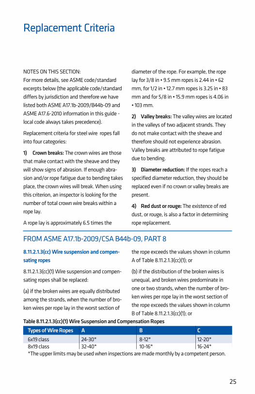
8.11.2.1.3(cc) Wire suspension and compen-sating ropes
8.11.2.1.3(cc)(1) Wire suspension and compen-sating ropes shall be replaced:
(a) if the broken wires are equally distributed among the strands, when the number of bro-ken wires per rope lay in the worst section of
the rope exceeds the values shown in column A of Table 8.11.2.1.3(cc)(1); or
(b) if the distribution of the broken wires is unequal, and broken wires predominate in one or two strands, when the number of bro-ken wires per rope lay in the worst section of the rope exceeds the values shown in column B of Table 8.11.2.1.3(cc)(1); or
Replacement Criteria
Table 8.11.2.1.3(cc)(1) Wire Suspension and Compensation Ropes Types of Wire Ropes A B C 6x19 class 24-30* 8-12* 12-20* 8x19 class 32-40* 10-16* 16-24* *The upper limits may be used when inspections are made monthly by a competent person.
NOTES ON THIS SECTION:For more details, see ASME code/standard excerpts below (the applicable code/standard differs by jurisdiction and therefore we have listed both ASME A17.1b-2009/B44b-09 and ASME A17.6-2010 information in this guide - local code always takes precedence).
Replacement criteria for steel wire ropes fall into four categories:
1) Crown breaks: The crown wires are those that make contact with the sheave and they will show signs of abrasion. If enough abra-sion and/or rope fatigue due to bending takes place, the crown wires will break. When using this criterion, an inspector is looking for the number of total crown wire breaks within a rope lay.
A rope lay is approximately 6.5 times the
diameter of the rope. For example, the rope lay for 3/8 in • 9.5 mm ropes is 2.44 in • 62 mm, for 1/2 in • 12.7 mm ropes is 3.25 in • 83 mm and for 5/8 in • 15.9 mm ropes is 4.06 in • 103 mm.
2) Valley breaks: The valley wires are located in the valleys of two adjacent strands. They do not make contact with the sheave and therefore should not experience abrasion. Valley breaks are attributed to rope fatigue due to bending.
3) Diameter reduction: If the ropes reach a specified diameter reduction, they should be replaced even if no crown or valley breaks are present.
4) Red dust or rouge: The existence of red dust, or rouge, is also a factor in determining rope replacement.
FROM ASME A17.1b-2009/CSA B44b-09, PART 8
26
Replacement CriteriaFROM ASME A17.1b-2009/CSA B44b-09, PART 8
(c) if four or five wires, side by side, are broken across the crown of any strand, when the number of broken wires per rope lay in the worst section of rope exceeds values shown in column C of Table 8.11.2.1.3(cc)(1); or
(d) if in the judgment of the inspector, any unfavorable condition, such as fretting cor-rosion (red dust or rouge), excessive wear of individual wires in the strands, unequal ten-sion, poor sheave grooves, etc., exists, the cri-teria for broken wires will be reduced by 50% of the values indicated in Table 8.11.2.1.3(cc)(1) for any of the three conditions described above; or
(e) if there is more than one valley break per rope lay.
8.11.2.1.3(cc)(2) On winding drum machines, the ropes shall be replaced:
(a) if the broken wires are equally distributed among the strands, when the number of bro-ken wires per rope lay in the worst section of rope exceeds 12 to 18; or
(b) if wire breaks predominate in one or two strands, when the number of broken wires per rope lay in the worst section of rope exceeds 6 to 12; or
(c) if there is more than one valley break per rope lay.
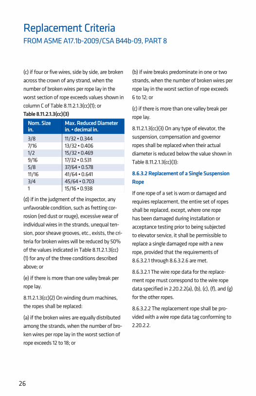
8.11.2.1.3(cc)(3) On any type of elevator, the suspension, compensation and governor ropes shall be replaced when their actual diameter is reduced below the value shown in Table 8.11.2.1.3(cc)(3):
8.6.3.2 Replacement of a Single Suspension Rope
If one rope of a set is worn or damaged and requires replacement, the entire set of ropes shall be replaced, except, where one rope has been damaged during installation or acceptance testing prior to being subjected to elevator service, it shall be permissible to replace a single damaged rope with a new rope, provided that the requirements of 8.6.3.2.1 through 8.6.3.2.6 are met.
8.6.3.2.1 The wire rope data for the replace-ment rope must correspond to the wire rope data specified in 2.20.2.2(a), (b), (c), (f), and (g) for the other ropes.
8.6.3.2.2 The replacement rope shall be pro-vided with a wire rope data tag conforming to 2.20.2.2.
Table 8.11.2.1.3(cc)(3) Nom. Size Max. Reduced Diameter in. in. • decimal in. 3/8 11/32 • 0.344 7/16 13/32 • 0.406 1/2 15/32 • 0.469 9/16 17/32 • 0.531 5/8 37/64 • 0.578 11/16 41/64 • 0.641 3/4 45/64 • 0.703 1 15/16 • 0.938

27
Replacement CriteriaFROM ASME A17.1b-2009/CSA B44b-09, PART 8
8.6.3.2.3 The suspension ropes, including the damaged rope, shall not have been shortened since their original installation.
8.6.3.2.4 The diameter of any of the remain-ing ropes shall not be less than the nominal diameter minus 0.4 mm (0.015 in.).
8.6.3.2.5 The tension of the new replacement rope shall be checked and adjusted as neces-sary at semi-monthly intervals over a period of not less than two months after installation. If proper equalization of rope tension cannot be maintained after six months, the entire set of hoist ropes shall be replaced.
8.6.3.2.6 The replacement rope shall be pro-vided with the same type of suspension-rope fastening used with the other ropes.
8.6.3.3 Replacement of Ropes Other than Governor Ropes
8.6.3.3.1 Replacement of all ropes, except governor ropes (see 8.6.3.4) shall conform to the following:
(a) Replacement ropes shall be as specified by the original elevator manufacturer or be at least equivalent in strength, weight, and design.
(b) Ropes that have been previously used in another installation shall not be reused.
(c) When replacing suspension, compensat-ing, and car or drum counterweight ropes, all ropes in a set shall be replaced, except as permitted by 8.6.3.2.
(d) The ropes in the set shall be new, all from the same manufacturer, and of the same material, grade, construction, and diameter.
(e) Data tags conforming to 2.20.2.2 shall be applied.
(f) Suspension, car, and drum counterweight rope fastenings shall conform to 2.20.9.
8.6.3.4 Replacement of Governor or Safety Rope
8.6.3.4.1 Governor ropes shall be of the same size, material, and construction as the rope specified by the governor manufacturer, except that a rope of the same size but of different material or construction shall be permitted to be installed in conformance with 8.7.2.19.
8.6.3.4.2 The replaced governor ropes shall comply with 2.18.5.
8.6.3.4.3 After a governor rope is replaced, the governor pull-through force shall be checked as specified in 8.11.2.3.2(b).
8.6.3.4.4 A test tag indicating the date when the pull-through test was performed shall be attached.
NOTE: Some in the industry believe that all ropes for an installation must be cut from the same master reel. This is not stated in ASME A17.1/CSA B44.

28
Replacement CriteriaFROM ASME A17.6-2010, SECTION 1.10
Notes:(1) Replacement criteria for steel wire rope are based on the worst conditions of diameter and wire breaks. Crown wires are subject to both wear that reduces the diameter of the rope and the breaks that occur in the wear area. Breaks that are visible and occur outside of the crown wear area with the crown wire intact are called valley breaks.
(2) Where ropes are subjected to reverse bends or where ropes are installed on non-metallic sheaves or sheaves with nonmetallic liners or inserts, extra attention must be given to the rope due to possible acceleration of val-ley breaks.
1.10.1 Traction Drive Machines1.10.1.1 Replacement requirements for steel wire suspension ropes for traction eleva-tors shall be as follows (see Nonmandatory Appendix A):
(a) The steel wire rope(s) shall be replaced if the rope is permanently kinked, bent, or deformed in any way (see 1.10.5).
(b) For rope diameters equal to or greater than 8 mm (0.315 in.), the ropes shall be replaced in accordance with 1.10.1.2(a) through 1.10.1.2(g) and 1.10.3.
(c) For rope diameters less than 8 mm (0.315 in.), the ropes shall be replaced in accordance with 1.10.1.2(a) through (g), 1.10.1.2.1 and 1.10.1.2.2, and 1.10.3. In addition, other replace-ment criteria based on the application shall be permitted to be applied. The replacement cri-
teria shall be documented in the Maintenance Control Program (see ASME A17.1/CSA B44, requirement 8.6.1.4.1).
1.10.1.2 Criteria for replacement include at least one of the following:
(a) if the broken crown wires are equally dis-tributed among the strands, when the num-ber of broken wires per rope lay in the worst section of rope exceeds the values shown in the “Normal Wear Conditions,” first column of Table 1.10.1.2-1
(b) if the distribution of breaks is unequal and broken crown wires predominate in one or two strands, when the number of broken wires per rope lay in the worst section of rope or the minimum diameter exceeds the values shown in the “Normal Wear Conditions,” first column of Table 1.10.1.2-1
(c) if four wires, side by side, are broken across the crown of any strand, when the number of broken wires per rope lay in the worst sec-tion of rope exceeds the values shown in the “Normal Wear Conditions,” first column of Table 1.10.1.2-1
(d) if an unfavorable condition exists, such as but not limited to corrosion due to exter-nal conditions, excessive wear of individual wires in the strands, unequal tension, poor sheave grooves; the criteria for broken crown wires shall be the values indicated in the “Unfavorable Wear Conditions,” second column of Table 1.10.1.2-1 for any of the condi-tions described above

29
Replacement CriteriaFROM ASME A17.6-2010, SECTION 1.10
(e) if red dust or rouge exists, the criteria for broken wires shall be the values indicated in the “Rope Showing Rouge,” third column of Table 1.10.1.2-1 for any of the conditions described above
(f) if there is more than one valley break per rope lay
(g) if there are any valley breaks at any loca-tion where rouge exists
1.10.1.2.1 The elevator manufacturer using information from the rope manufacturer and considering the application, shall estab-lish the design life limit to ensure that the residual strength of wire ropes less than 8 mm (0.315 in.) diameter is not less than 60%
of the minimum breaking force at the time of replacement.
1.10.1.2.2 Steel wire ropes of less than 8 mm (0.315 in.) in diameter shall be replaced when there is evidence of rouge.
1.10.2 Winding Drum MachinesSuspension ropes shall be replaced on wind-ing drum machines if:
(a) the broken crown wires are equally distrib-uted among the strands, when the number of broken wires per rope lay in the worst section of rope exceeds 12;
(b) the broken crown wires predominate in one or two strands, when the number of bro-
Table 1.10.1.2-1 Wire Breaks: Crown Wire Breaks Per Lay Length 6-Strand Normal Wear Unfavorable Wear Ropes Rope Applications Conditions Conditions Showing Rouge Distributed breaks (max.) 24 12 12 Unequal breaks (max.) 8 4 4 4 Side-by-Side breaks 12 6 6
8 and 9-Strand Normal Wear Unfavorable Wear Ropes Rope Applications Conditions Conditions Showing Rouge Distributed breaks (max.) 32 16 16 Unequal breaks (max.) 10 5 5 4 Side-by-Side breaks 16 8 8
General notes:(a) Where ropes are subjected to reverse bends or where ropes are installed on nonmetallic coated, plastic, fiber-reinforced plastic sheaves or sheaves with nonmetallic liners or inserts, extra attention must be given to any steel wire rope (6, 8, or 9 strand) due to possible accelera-tion of valley breaks.
(b) This table does not apply to Winding Drum Machines. See 1.10.2 for replacement criteria.
(c) No more than one valley break per lay length and no valley breaks allowed if visible rouge.
(d) For ropes less than 8 mm, also see 1.10.1.2.2 for additional replacement requirements.

30
Replacement CriteriaFROM ASME A17.6-2010, SECTION 1.10
ken wires per rope lay in the worst section of rope exceeds 6;
(c) there is more than one valley break per rope lay; or
(d) there are any valley breaks at any location where rouge exists.
1.10.3 All Elevator TypesThe suspension, compensation, and governor ropes shall be replaced when their actual diameter is reduced below the value shown in Table 1.10.3-1 (see page 32). For nominal diameters not listed in Table 1.10.3-1, the minimum diameter reduction shall be cal-culated using the criteria outlined in General Notes (a) and (b) of Table 1.10.3-1. Normal wear diameters, unfavorable wear, and rouge conditions as listed in the table shall apply. Compensation and governor ropes shall also conform to 1.10.1.1(a) and 1.10.1.2(a) through 1.10.1.2(g).
Measurement for diameter shall be taken on a straight portion of rope at the worst location. Two measurements at the same position at right angles shall be taken. The ropes shall be replaced if both of these mea-surements are below the replacement value. However, if only one of the measurements is below the replacement value, then the criteria
for wire breaks under “Unfavorable Wear Conditions” shall apply. See Table 1.10.1.2-1.
1.10.4 Replacement of RopesReplacement of all ropes, except governor ropes (see ASME A17.1/CSA B44, requirement 8.6.3.4), shall conform to the requirements of 1.10.4.1 through 1.10.4.6.
1.10.4.1 Replacement ropes shall be as speci-fied by the original elevator manufacturer or be at least equivalent in strength, weight, and design.
1.10.4.2 Ropes that have previously been installed and used on another installation shall not be reused.
1.10.4.3 When replacing suspension, compen-sating, and car or drum counterweight ropes, all ropes in a set shall be replaced, except as permitted by 1.10.5.
1.10.4.4 The ropes in the set shall be new, all from the same manufacturer and of the same material, grade, construction, and diameter.
1.10.4.5 Data tags conforming to ASME A17.1/CSA B44, requirement 2.20.2.2 shall be applied.
1.10.4.6 Suspension, car, and drum coun-terweight rope fastenings shall conform to ASME A17.1/CSA B44, requirement 2.20.9.

31
Replacement CriteriaFROM ASME A17.6-2010, SECTION 1.10
1.10.5 Replacement of a Single Suspension RopeIf one rope of a set is worn or damaged and requires replacement, the entire set of ropes shall be replaced; except, where one rope has been damaged during installation or acceptance testing prior to being subjected to elevator service, it shall be permissible to replace a single damaged rope with a new rope provided that the requirements of 1.10.4.4 and 1.10.5.1 through 1.10.5.1.6 are met. NOTE: Damage includes but is not limited to kinked ropes.
1.10.5.1 The steel wire rope data for the replacement rope must correspond to the steel wire rope data specified in ASMEA17.1/CSA B44, requirement 2.20.2.2.
1.10.5.2 The replacement rope shall be provid-ed with a data tag conforming to ASME A17.1/CSA B44, requirement 2.20.2.2.
1.10.5.3 The suspension ropes, including the damaged rope, shall not have been shortened since their original installation.
1.10.5.4 The diameter of any of the remain-ing ropes shall not be less than the nominal diameter minus 0.4 mm (0.015 in.).
1.10.5.5 The tension of the new replacement rope shall be checked and adjusted as neces-sary at semi-monthly intervals over a period of not less than 2 months after installation. If proper equalization of the rope tension can-not be maintained after 6 months, the entire set of suspension ropes shall be replaced.
1.10.5.6 The replacement rope shall be pro-vided with the same type of suspension rope fastening used with the other ropes.
NOTE: Some in the industry believe that all ropes for an installation must be cut from the same master reel. This is not stated in ASME 17.6.

32
Table 1.10.3-1 Imperial Minimum Diameter 6-, 8-, and 9-Strand Rope Applications Nominal Normal or Ropes Rope Unfavorable Showing Size Wear Conditions Rouge 1⁄4 in. 0.242 in. Note (1) 5⁄16 in. 0.303 in. Note (1) 3⁄8 in. 0.352 in. 0.363 in. 7⁄16 in. 0.410 in. 0.424 in. 1⁄2 in. 0.469 in. 0.484 in. 9⁄16 in. 0.527 in. 0.545 in. 5⁄8 in. 0.586 in. 0.605 in. 11⁄16 in. 0.645 in. 0.666 in. 3⁄4 in. 0.703 in. 0.727 in. 13⁄16 in. 0.762 in. 0.787 in. 7⁄8 in. 0.820 in. 0.848 in. 15⁄16 in. 0.879 in. 0.908 in. 1 in. 0.938 in. 0.969 in. 1 1⁄8 in. 1.055 in. 1.090 in. 1 1⁄4 in. 1.172 in. 1.211 in. 1 3⁄8 in. 1.289 in. 1.332 in. 1 1⁄2 in. 1.406 in. 1.453 in.
GENERAL NOTES:(a) Maximum allowable diameter reduction below nominal for rope diameters less than 8 mm is 3.125%.(b) Maximum allowable diameter reduction below nominal for rope diameters equal to or greater than 8 mm are as follows: (1) Normal wear or unfavorable wear conditions is 6.25%. (2) Ropes showing rouge is 3.125%.NOTE: (1) For ropes less than 8 mm, the rope must be replaced if rouge is evident. See 1.10.1.2.2.
Table 1.10.3-1 Metric Minimum Diameter 6-, 8-, and 9-Strand Rope Applications Nominal Normal or Ropes Rope Unfavorable Showing Size Wear Conditions Rouge 4 mm 3.875 mm Note (1) 5 mm 4.844 mm Note (1) 6 mm 5.813 mm Note (1) 6.5 mm 6.297 mm Note (1) 6.7 mm 6.491 mm Note (1) 8 mm 7.500 mm 7.750 mm 9 mm 8.438 mm 8.719 mm 10 mm 9.375 mm 9.688 mm 11 mm 10.31 mm 10.66 mm 12 mm 11.25 mm 11.63 mm 13 mm 12.19 mm 12.59 mm 14 mm 13.13 mm 13.56 mm 15 mm 14.06 mm 14.53 mm 16 mm 15.00 mm 15.50 mm 18 mm 16.88 mm 17.44 mm 19 mm 17.81 mm 18.41 mm 20 mm 18.75 mm 19.38 mm 22 mm 20.63 mm 21.31 mm
Replacement CriteriaFROM ASME A17.6-2010, SECTION 1.10


![wire rope[1]](https://img.pdfslide.net/doc/110x75/54767163b4af9fa30a8b62a6/wire-rope1.jpg)