Embed Size (px)
Citation preview
Wireless ADSL2+ Router User’s Guide
WELL DA-300N Wireless ADSL2+ Router
User’s Manual
1
Wireless ADSL2+ Router User’s Guide
Table of Contents
1 ..........................................................8 Introduction
Features ................................................................................8
Device Requirements ...........................................................8
Using this Document.............................................................9
Notational conventions ..................................................9
Typographical conventions............................................9
Special messages..........................................................9
Getting Support.....................................................................9
2 ................................10 Getting to know the device
Computer / System requirements ......................................10
Package Contents ..............................................................10
For Annex-B 802.11n WLAN ADSL2+ Router .......................................................................10
For Annex-A 802.11n WLAN ADSL2+ Router .......................................................................10
Installation & Setup.............................................................11
LED meanings & activations ..............................................13
Back Panel Connectors ...............................................14
3
...................................................16
Computer configurations under different OS, to obtain IP address automatically
4 ...........................................24 Utility CD execution
Connecting the Hardware...................................................24
Wireless Connection...........................................................30
5 .................32 Getting Started with the Web pages
Accessing the Web pages..................................................32
Testing your Setup..............................................................35
Default device settings........................................................35
6 ...........................................................37 Overview
Internet access settings......................................................39
About Wireless ADSL2+ Router.........................................39
7 ................................................................40 Status
Device Info ..........................................................................40
ADSL...................................................................................42
Statistics ..............................................................................43
8 ..................................................44 Internet Access
Types of Internet Access ....................................................45
2
Wireless ADSL2+ Router User’s Guide
Configuring your PPPoE DSL connection .........................46
Configuring your PPPoA DSL connection .........................48
Configuring your Bridged DSL connection.........................50
Configuring your 1483 MER by DHCP ..............................51
Configuring your 1483 MER by Fixed IP ...........................52
ATM Settings.......................................................................54
ADSL Settings.....................................................................56
9 .............................59 Local Network Configuration
Changing the LAN IP address and subnet mask ................................................................................59
Adding the Secondary LAN IP address and subnet mask ....................................................................64
10 ..................................................65 DHCP Settings
DHCP Server Configuration ...............................................65
DHCP Relay Configuration.................................................67
DHCP None Configuration .................................................69
11 ................................71 DHCP Static Configuration
DHCP Static Configuration.................................................71
12 .....................................72 LAN IPv6 Configuration
DHCP Static Configuration.................................................72
13 ..............................................73 Wireless Network
Basic Settings .....................................................................73
Security................................................................................75
WEP + Encryption Key ................................................77
WEP + Use 802.1x Authentication..............................78
WPA/WPA2/WPA2 Mixed + Personal (Pre-Shared Key)......................................................78
WPA/WPA2/WPA2 Mixed + Enterprise (RADIUS)..................................................................80
Wireless Multiple BSSID Settings ......................................81
Access Control....................................................................83
Allow Listed ..................................................................84
Deny Listed ..................................................................84
Advanced Settings..............................................................86
WPS ....................................................................................89
Introduction of WPS.....................................................89
Supported WPS features.............................................89
AP mode.......................................................................90
AP as Enrollee .............................................................90
AP as Registrar............................................................90
3
Wireless ADSL2+ Router User’s Guide
AP as Proxy .................................................................90
Infrastructure-Client mode ...........................................90
Instructions of AP’s and Client’s operations .................................................................91
Operations of AP - AP being an enrollee...........................93
Operations of AP - AP being a registrar...........................104
AP mode.....................................................................104
Push Button method ..................................................108
14 ............................................................112 Routing
Static Route.......................................................................112
IPv6 Static Route ..............................................................114
RIP.....................................................................................115
15 .................................................................117 DMZ
Configuring DMZ...............................................................117
16 ...................................................119 Virtual Server
Configuring Virtual Server.................................................119
Configuring custom applications ......................................120
Virtual Server for FTP ................................................121
Port Forwarding for HTTP .........................................124
Deleting custom applications.....................................126
17 ..............................................128 NAT Forwarding
Configuring NAT Forwarding............................................128
18 .................................................................129 ALG
Configuring ALG ...............................................................129
19 ...............................................130 NAT Exclude IP
Configuring NAT Exclude IP.............................................130
20 .....................................................131 Port Trigger
Configuring Port Trigger ...................................................131
21 .................................................132 FTP ALG Portl
Configuring Port Trigger ...................................................132
22 ................................................133 Nat IP Mapping
Configuring Port Trigger ...................................................133
23 .............................................................134 IP QoS
IP QoS...............................................................................134
24 .................................................136 CWMP Config
CWMP Configuration........................................................136
25 ...................................................138 Port Mapping
Port Mapping.....................................................................138
4
Wireless ADSL2+ Router User’s Guide
26 ...........................................................141 Bridging
Bridging .............................................................................141
27 .......................................................142 Client Limit
Client Limit.........................................................................142
28 ..............................................................142 Others
Others................................................................................142
29 .....................................................143 IGMP Proxy
IGMP Proxy.......................................................................143
30 ...............................................................144 UPnP
Configuring UPnP.............................................................145
UPnP Control Point Software on Windows ME..................................................................................146
UPnP Control Point Software on Windows XP with Firewall .............................................................146
SSDP requirements ...................................................147
31 ..............................................................150 SNMP
SNMP................................................................................150
32 ..........................................151 DNS Configuration
DHCP Server Configuration - Attain DNS Automatically .................................................................151
DHCP Server Configuration - Set DNS Manually.........................................................................152
IPv6 DNS...........................................................................153
33 ...........................154 Dynamic DNS Configuration
Overview of Dynamic DNS...............................................154
Dynamic DNS Configuration – DynDNS.org ...................156
Dynamic DNS Configuration – TZO.................................158
34 ...................................................160 MAC Filtering
Configuring MAC filtering to Deny for outgoing access.............................................................160
35 ................................................162 IP/Port Filtering
IP/Port Filtering..................................................................162
36 ........................................................164 URL Filter
Configuring URL Blocking of Keyword.............................164
37 ...........................................166 ACL Configuration
ACL Config........................................................................166
38 .................................................................167 DoS
DoS Config........................................................................167
39 .............................................168 Firmware Update
About firmware versions ...................................................168
5
Wireless ADSL2+ Router User’s Guide
Manually updating firmware..............................................168
40 ...............................................173 Backup/Restore
Backup settings.................................................................173
Restore settings ................................................................174
41 .........................................................175 Password
Setting your username and password .............................175
42 ...............................................177 Commit/Reboot
Commit ..............................................................................177
Reboot...............................................................................178
Resetting to Defaults.........................................................178
43 .......................................................180 Time Zone
SNTP Server and SNTP Client Configuration settings....................................................180
44 ...................................................................186 Log
Log.....................................................................................186
45 ........................................................187 Diagnostic
Ping ...................................................................................187
Ping6 .................................................................................188
Tracert ...............................................................................189
ATM Loopback..................................................................189
ADSL Diagnostic...............................................................191
Diagnostic Test .................................................................192
A ...........................194 Configuring your Computers
Configuring Ethernet PCs.................................................194
Before you begin........................................................194
Windows® XP PCs....................................................194
Windows 2000 PCs ...................................................194
Windows Me PCs ......................................................196
Windows 95, 98 PCs .................................................196
Windows NT 4.0 workstations...................................197
Assigning static Internet information to your PCs .................................................................198
B ........................................................199
IP Addresses, Network Masks, and Subnets
IP Addresses.....................................................................199
Structure of an IP address.........................................199
Network classes.........................................................199
Subnet masks ...................................................................200
C ...............................................202 Troubleshooting
6

Wireless ADSL2+ Router User’s Guide
Troubleshooting Suggestions...........................................202
Diagnosing Problem using IP Utilities ..............................204
ping.............................................................................204
nslookup.....................................................................205
D ..........................................................206 Glossary
7
Wireless ADSL2+ Router User’s Guide
1 Introduction
Congratulations on becoming the owner of the Wireless ADSL2+ Router. You will now be able to access the Internet using your high-speed DSL connection.
This User Guide will show you how to connect your Wireless ADSL2+ Router, and how to customize its configuration to get the most out of your new product.
Features
The list below contains the main features of the device and may be useful to users with knowledge of networking protocols. If you are not an experienced user, the chapters throughout this guide will provide you with enough information to get the most out of your device.
Features include:
Internal DSL modem for high-speed Internet access
10/100Base-T Ethernet Router to provide Internet connectivity to all computers on your LAN
Network address translation (NAT) functions to provide security for your LAN
Network configuration through DHCP Server and DHCP Client
Services including IP route and DNS configuration, RIP, and IP and DSL performance monitoring
User-friendly configuration program accessed via a web browser
User-friendly configuration program accessed via EasySetup program
Device Requirements
In order to use the Wireless ADSL2+ Router, you must have the following:
DSL service up and running on your telephone line
Instructions from your ISP on what type of Internet access you will be using, and the addresses needed to set up access
One or more computers each containing an Ethernet card (10Base-T/100Base-T network interface card (NIC))
For system configuration using the supplied a. web-based program: a web browser such as Internet Explorer v4 or later, or Netscape v4 or later. Note that version 4 of each browser is the minimum version requirement – for optimum display quality, use Internet Explorer v5, or Netscape v6.1 b. EasySetup program: Graphical User Interface
8
Wireless ADSL2+ Router User’s Guide
Note
You do not need to use a hub or switch in order to connect more than one Ethernet PC to your device. Instead, you can connect up to four Ethernet PCs directly to your device using the ports labeled Ethernet on the rear panel.
Using this Document
Notational conventions
Acronyms are defined the first time they appear in the text and also in the glossary.
For brevity, the Wireless ADSL2+ Router is referred to as “the device”.
The term LAN refers to a group of Ethernet-connected computers at one site.
Typographical conventions
Italic text is used for items you select from menus and drop-down lists and the names of displayed web pages.
Bold text is used for text strings that you type when prompted by the program, and to emphasize important points.
Special messages
This document uses the following icons to draw your attention to specific instructions or explanations.
Note
Provides clarifying or non-essential information on the current topic.
Definition
Explains terms or acronyms that may be unfamiliar to many readers. These terms are also included in the Glossary.
WARNING
Provides messages of high importance, including messages relating to personal safety or system integrity.
Getting Support
Supplied by: Helpdesk Number: Website:
9
Wireless ADSL2+ Router User’s Guide
2 Getting to know the device
Computer / System requirements
1. Pentium 200MHZ processor or above
2. Windows 98SE, Windows Me, Windows 2000, Windows XP, Windows Vista and Windows 7
3. 64MB of RAM or above
4. 25MB free disk space
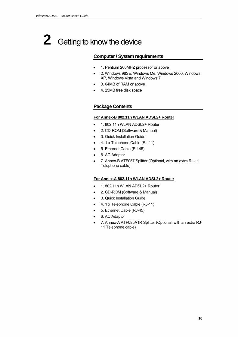
Package Contents
For Annex-B 802.11n WLAN ADSL2+ Router
1. 802.11n WLAN ADSL2+ Router
2. CD-ROM (Software & Manual)
3. Quick Installation Guide
4. 1 x Telephone Cable (RJ-11)
5. Ethernet Cable (RJ-45)
6. AC Adaptor
7. Annex-B ATF057 Splitter (Optional, with an extra RJ-11 Telephone cable)
For Annex-A 802.11n WLAN ADSL2+ Router
1. 802.11n WLAN ADSL2+ Router
2. CD-ROM (Software & Manual)
3. Quick Installation Guide
4. 1 x Telephone Cable (RJ-11)
5. Ethernet Cable (RJ-45)
6. AC Adaptor
7. Annex-A ATF085A1R Splitter (Optional, with an extra RJ-11 Telephone cable)
10
Wireless ADSL2+ Router User’s Guide
Installation & Setup
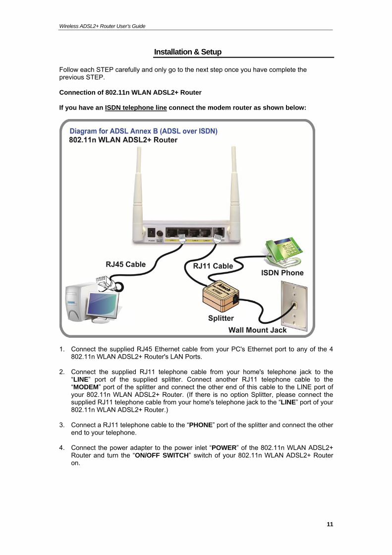
Follow each STEP carefully and only go to the next step once you have complete the previous STEP. Connection of 802.11n WLAN ADSL2+ Router If you have an ISDN telephone line connect the modem router as shown below:
1. Connect the supplied RJ45 Ethernet cable from your PC's Ethernet port to any of the 4
802.11n WLAN ADSL2+ Router's LAN Ports. 2. Connect the supplied RJ11 telephone cable from your home's telephone jack to the
“LINE” port of the supplied splitter. Connect another RJ11 telephone cable to the “MODEM” port of the splitter and connect the other end of this cable to the LINE port of your 802.11n WLAN ADSL2+ Router. (If there is no option Splitter, please connect the supplied RJ11 telephone cable from your home's telephone jack to the “LINE” port of your 802.11n WLAN ADSL2+ Router.)
3. Connect a RJ11 telephone cable to the “PHONE” port of the splitter and connect the other
end to your telephone. 4. Connect the power adapter to the power inlet “POWER” of the 802.11n WLAN ADSL2+
Router and turn the “ON/OFF SWITCH” switch of your 802.11n WLAN ADSL2+ Router on.
11
Wireless ADSL2+ Router User’s Guide
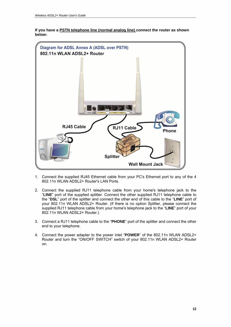
If you have a PSTN telephone line (normal analog line) connect the router as shown below:
1. Connect the supplied RJ45 Ethernet cable from your PC's Ethernet port to any of the 4
802.11n WLAN ADSL2+ Router's LAN Ports. 2. Connect the supplied RJ11 telephone cable from your home's telephone jack to the
“LINE” port of the supplied splitter. Connect the other supplied RJ11 telephone cable to the “DSL” port of the splitter and connect the other end of this cable to the “LINE” port of your 802.11n WLAN ADSL2+ Router. (If there is no option Splitter, please connect the supplied RJ11 telephone cable from your home's telephone jack to the “LINE” port of your 802.11n WLAN ADSL2+ Router.)
3. Connect a RJ11 telephone cable to the “PHONE” port of the splitter and connect the other
end to your telephone. 4. Connect the power adapter to the power inlet “POWER” of the 802.11n WLAN ADSL2+
Router and turn the “ON/OFF SWITCH” switch of your 802.11n WLAN ADSL2+ Router on.
12
Wireless ADSL2+ Router User’s Guide
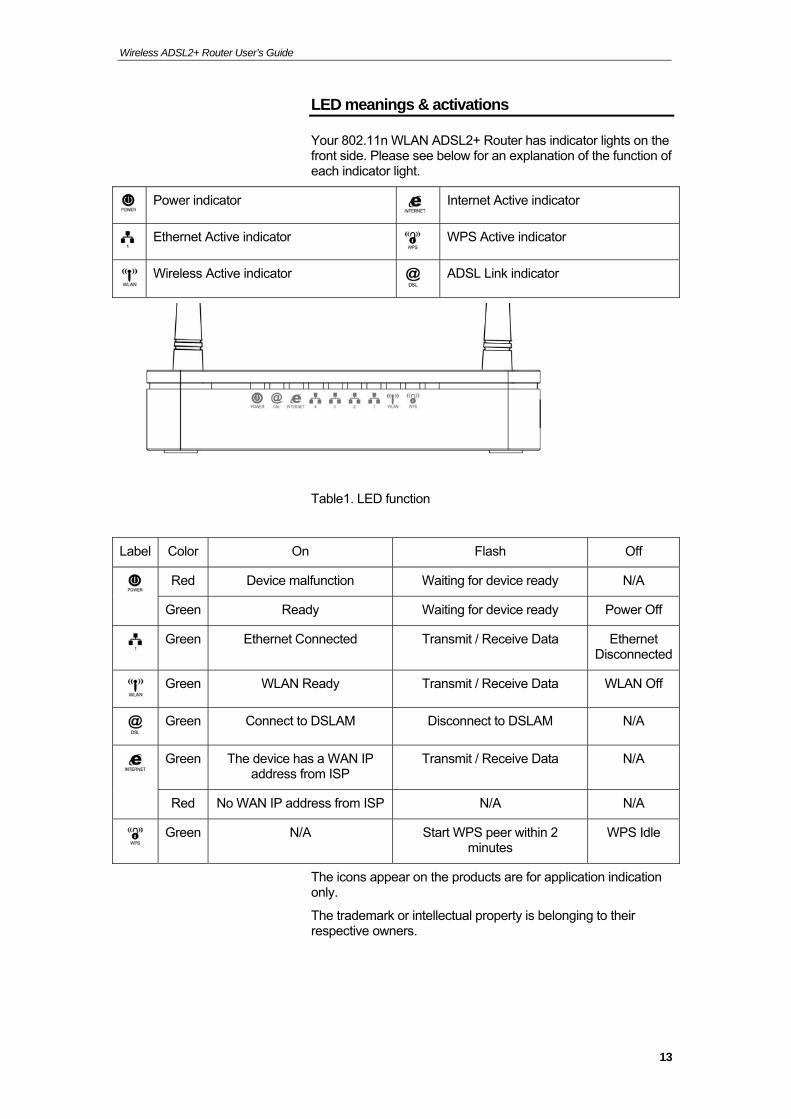
LED meanings & activations
Your 802.11n WLAN ADSL2+ Router has indicator lights on the front side. Please see below for an explanation of the function of each indicator light.
Power indicator
Internet Active indicator
Ethernet Active indicator
WPS Active indicator
Wireless Active indicator
ADSL Link indicator
Table1. LED function
Label Color On Flash Off
Red Device malfunction Waiting for device ready N/A
Green Ready Waiting for device ready Power Off
Green Ethernet Connected Transmit / Receive Data Ethernet
Disconnected
Green WLAN Ready Transmit / Receive Data WLAN Off
Green Connect to DSLAM Disconnect to DSLAM N/A
Green The device has a WAN IP address from ISP
Transmit / Receive Data N/A
Red No WAN IP address from ISP N/A N/A
Green N/A Start WPS peer within 2
minutes WPS Idle
The icons appear on the products are for application indication only.
The trademark or intellectual property is belonging to their respective owners.
13
Wireless ADSL2+ Router User’s Guide
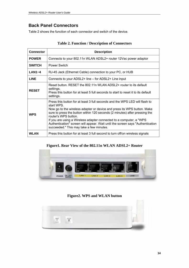
Back Panel Connectors Table 2 shows the function of each connector and switch of the device.
Table 2. Function / Description of Connectors
Connector Description
POWER Connects to your 802.11n WLAN ADSL2+ router 12Vac power adaptor
SWITCH Power Switch
LAN1~4 RJ-45 Jack (Ethernet Cable) connection to your PC, or HUB
LINE Connects to your ADSL2+ line – for ADSL2+ Line input
RESET
Reset button. RESET the 802.11n WLAN ADSL2+ router to its default settings. Press this button for at least 5 full seconds to start to reset it to its default settings.
WPS
Press this button for at least 3 full seconds and the WPS LED will flash to start WPS. Now go to the wireless adapter or device and press its WPS button. Make sure to press the button within 120 seconds (2 minutes) after pressing the router's WPS button. If you are using a Wireless adapter connected to a computer, a "WPS Authentication" screen will appear. Wait until the screen says "Authentication succeeded." This may take a few minutes.
WLAN Press this button for at least 3 full second to turn off/on wireless signals
Figure1. Rear View of the 802.11n WLAN ADSL2+ Router
Figure2. WPS and WLAN button
14

Wireless ADSL2+ Router User’s Guide
Figure3. RESET button
15
Wireless ADSL2+ Router User’s Guide
3 Computer configurations under different OS, to obtain IP address automatically
Before starting the 802.11n WLAN ADSL2+ Router configuration, please kindly configure the PC computer as below, to have automatic IP address / DNS Server.
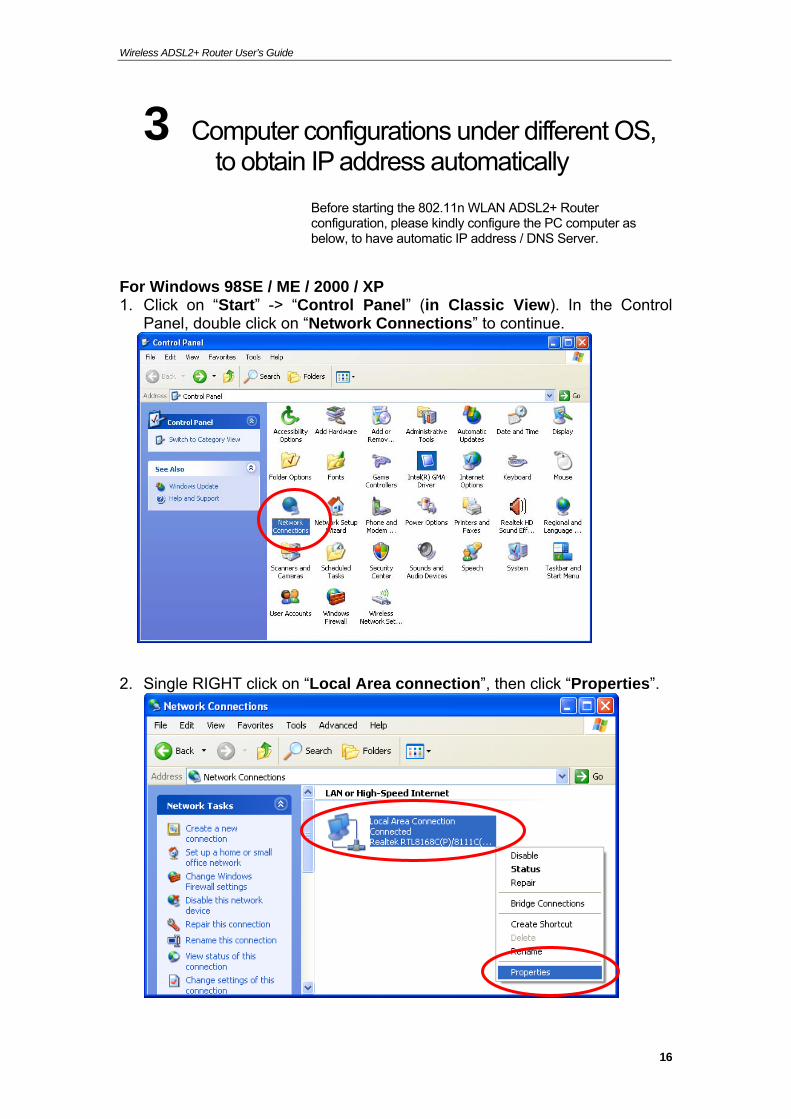
For Windows 98SE / ME / 2000 / XP 1. Click on “Start” -> “Control Panel” (in Classic View). In the Control
Panel, double click on “Network Connections” to continue.
2. Single RIGHT click on “Local Area connection”, then click “Properties”.
16
Wireless ADSL2+ Router User’s Guide
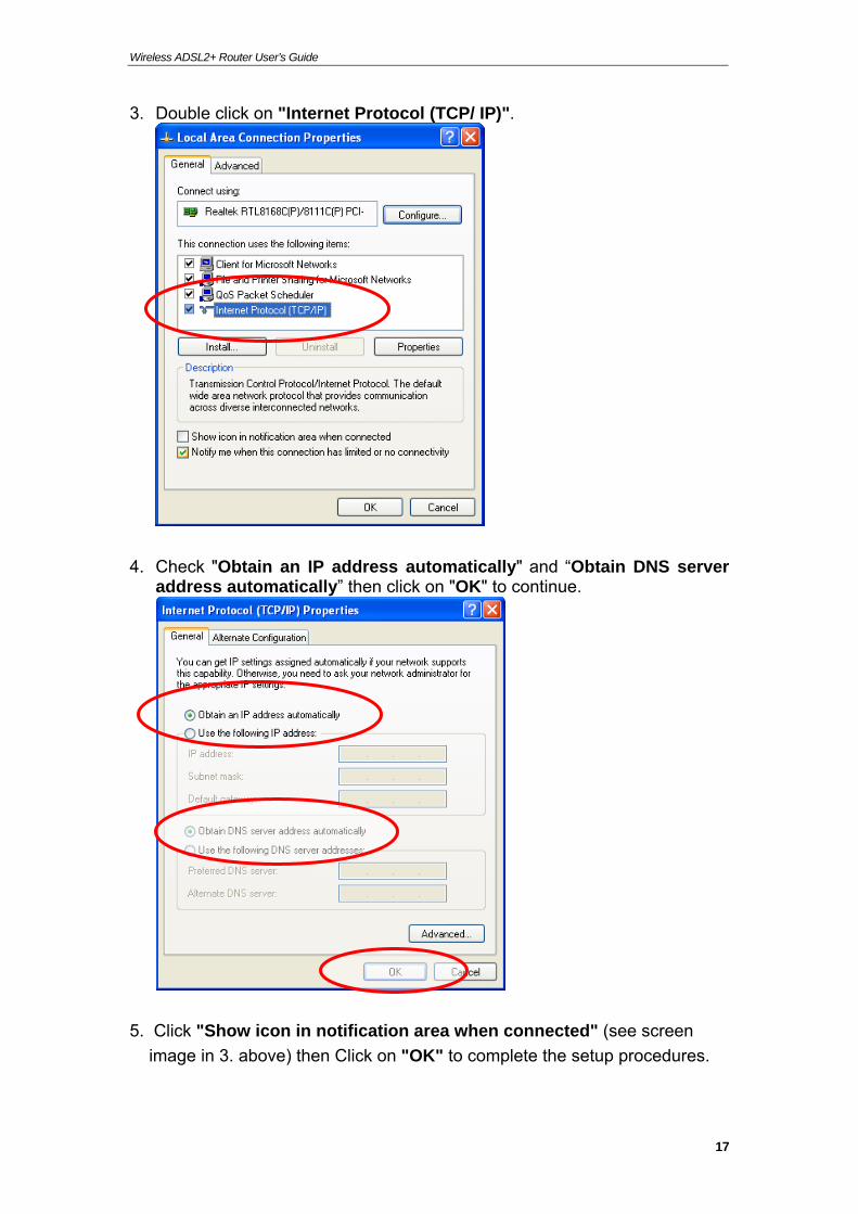
3. Double click on "Internet Protocol (TCP/ IP)".
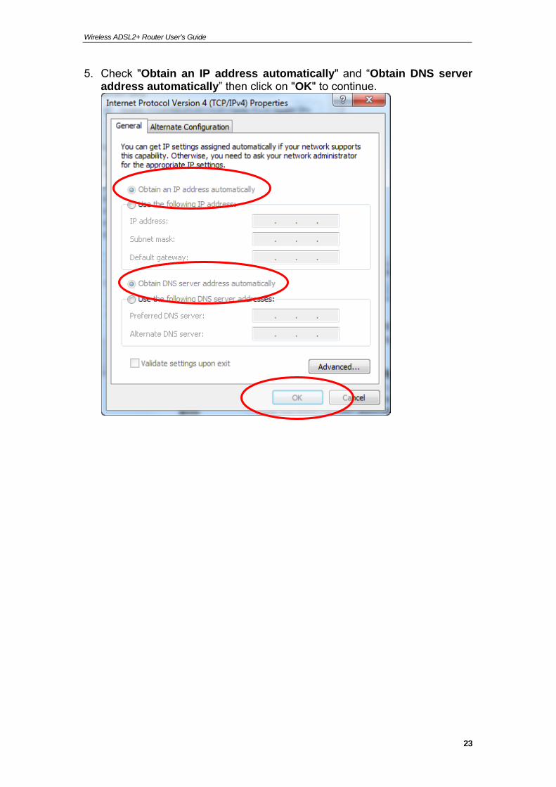
4. Check "Obtain an IP address automatically" and “Obtain DNS server address automatically” then click on "OK" to continue.
5. Click "Show icon in notification area when connected" (see screen
image in 3. above) then Click on "OK" to complete the setup procedures.
17
Wireless ADSL2+ Router User’s Guide
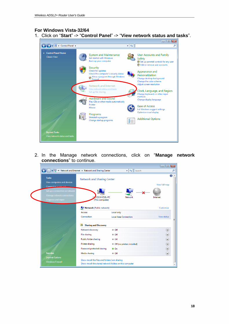
For Windows Vista-32/64 1. Click on “Start” -> “Control Panel” -> “View network status and tasks”.
2. In the Manage network connections, click on “Manage network connections” to continue.
18
Wireless ADSL2+ Router User’s Guide
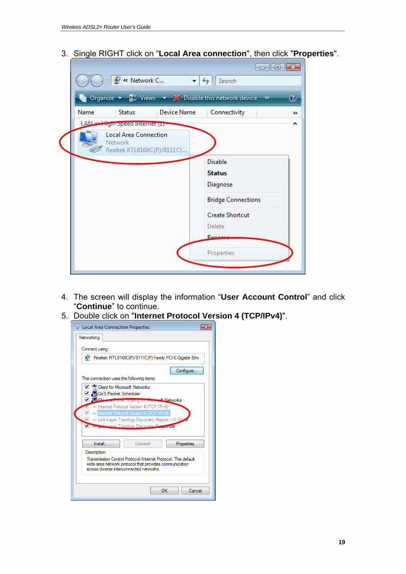
3. Single RIGHT click on “Local Area connection", then click "Properties".
4. The screen will display the information “User Account Control” and click “Continue” to continue.
5. Double click on "Internet Protocol Version 4 (TCP/IPv4)".
19
Wireless ADSL2+ Router User’s Guide
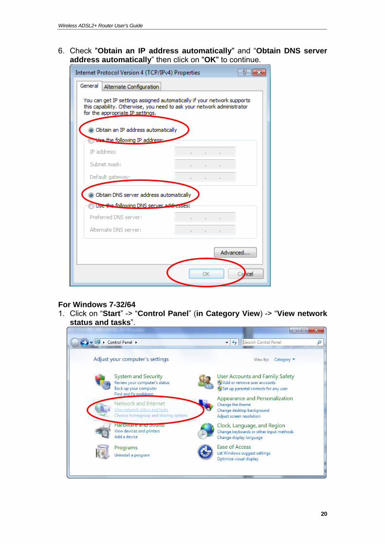
6. Check "Obtain an IP address automatically" and “Obtain DNS server address automatically” then click on "OK" to continue.
For Windows 7-32/64 1. Click on “Start” -> “Control Panel” (in Category View) -> “View network
status and tasks”.
20
Wireless ADSL2+ Router User’s Guide
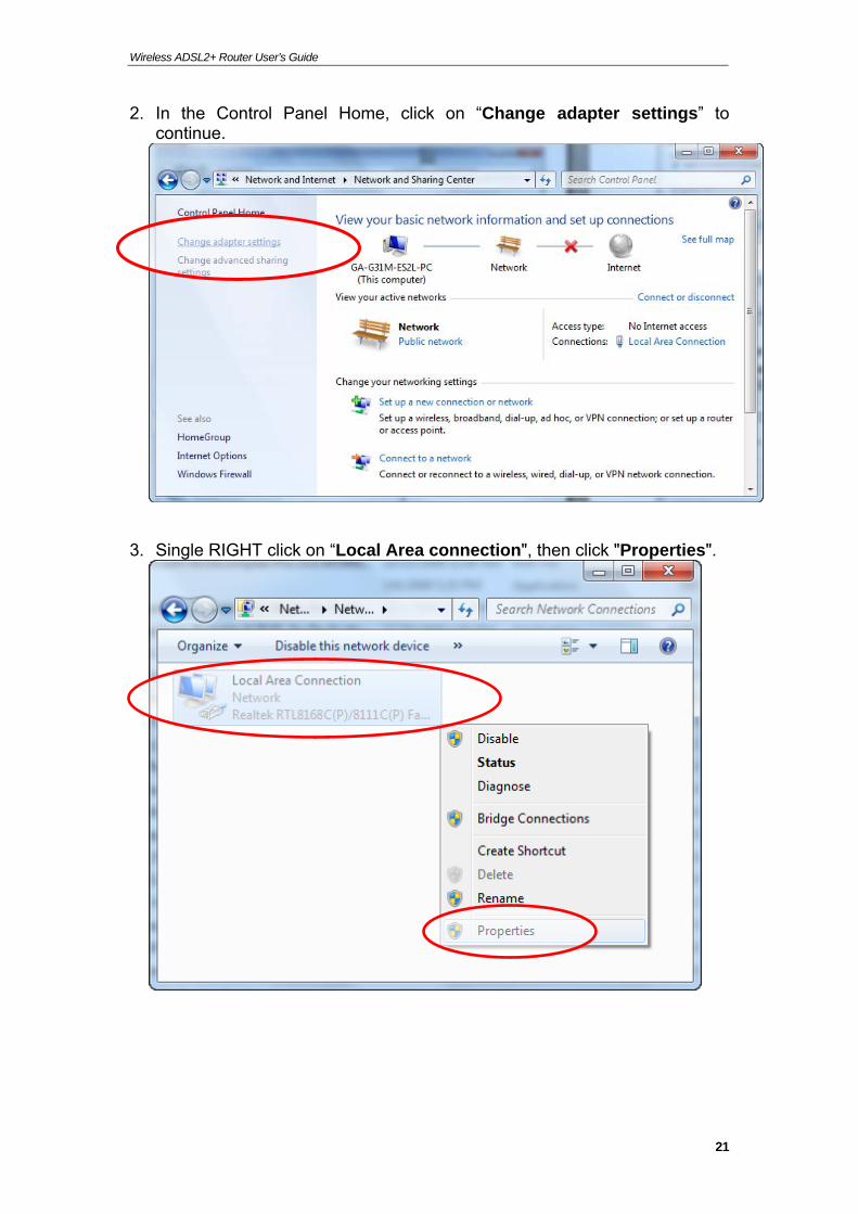
2. In the Control Panel Home, click on “Change adapter settings” to continue.
3. Single RIGHT click on “Local Area connection", then click "Properties".
21
Wireless ADSL2+ Router User’s Guide
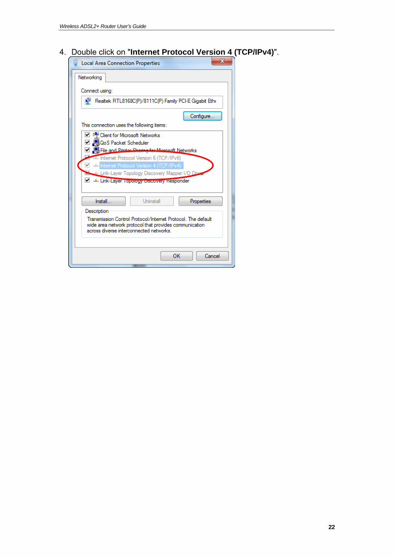
4. Double click on "Internet Protocol Version 4 (TCP/IPv4)".
22
Wireless ADSL2+ Router User’s Guide
5. Check "Obtain an IP address automatically" and “Obtain DNS server address automatically” then click on "OK" to continue.
23
Wireless ADSL2+ Router User’s Guide
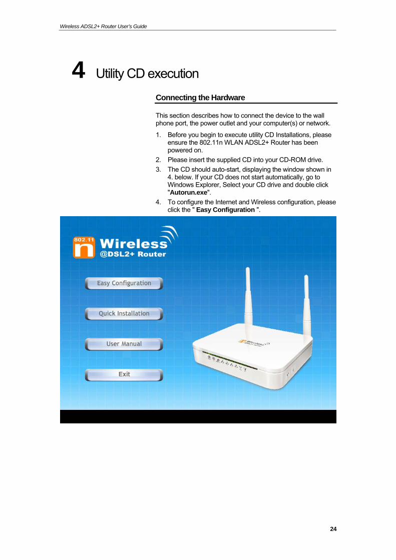
4 Utility CD execution
Connecting the Hardware
This section describes how to connect the device to the wall phone port, the power outlet and your computer(s) or network.
1. Before you begin to execute utility CD Installations, please ensure the 802.11n WLAN ADSL2+ Router has been powered on.
2. Please insert the supplied CD into your CD-ROM drive.
3. The CD should auto-start, displaying the window shown in 4. below. If your CD does not start automatically, go to Windows Explorer, Select your CD drive and double click "Autorun.exe".
4. To configure the Internet and Wireless configuration, please click the " Easy Configuration ".
24
Wireless ADSL2+ Router User’s Guide
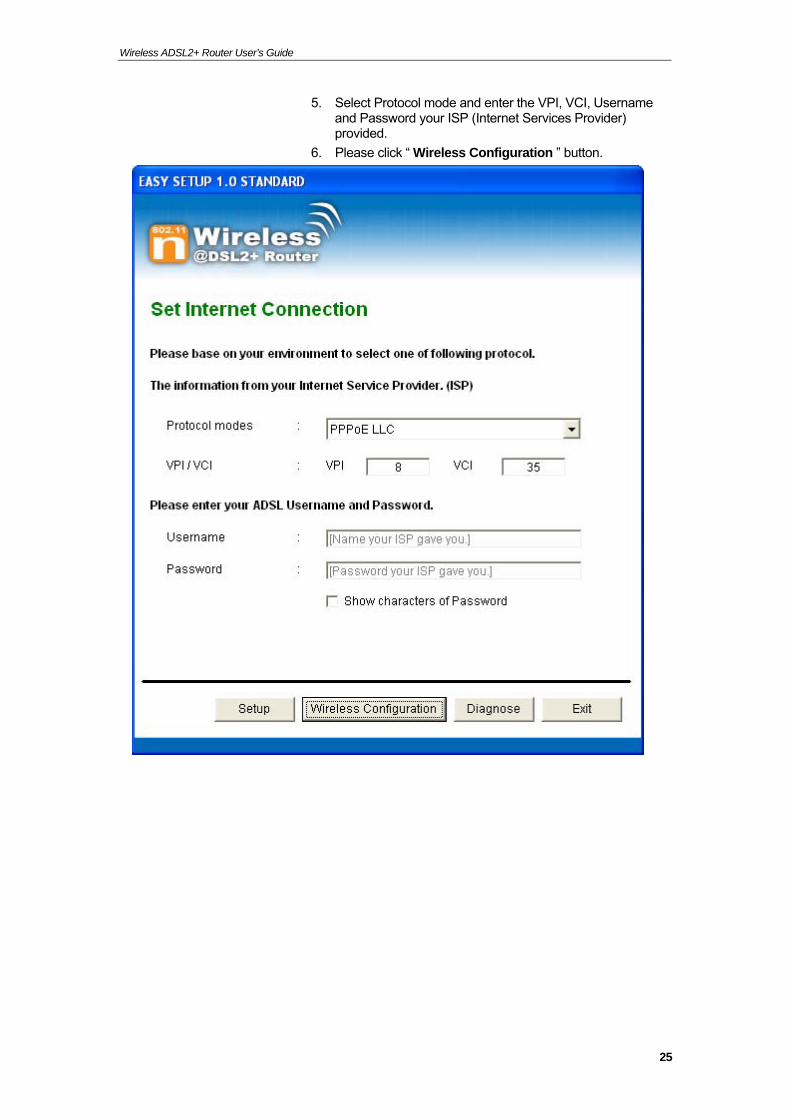
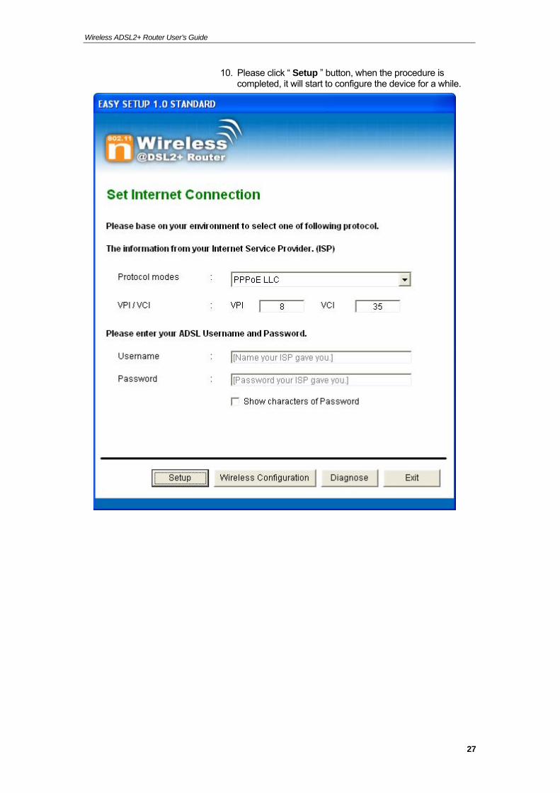
5. Select Protocol mode and enter the VPI, VCI, Username and Password your ISP (Internet Services Provider) provided.
6. Please click “ Wireless Configuration ” button.
25
Wireless ADSL2+ Router User’s Guide
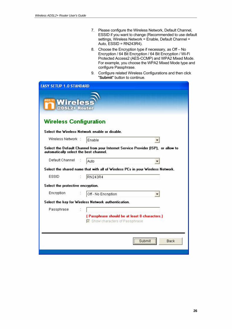
7. Please configure the Wireless Network, Default Channel, ESSID if you want to change (Recommended to use default settings, Wireless Network = Enable, Default Channel = Auto, ESSID = RN243R4).
8. Choose the Encryption type if necessary, as Off – No Encryption / 64 Bit Encryption / 64 Bit Encryption / Wi-Fi Protected Access2 (AES-CCMP) and WPA2 Mixed Mode. For example, you choose the WPA2 Mixed Mode type and configure Passphrase.
9. Configure related Wireless Configurations and then click "Submit" button to continue.
26
Wireless ADSL2+ Router User’s Guide
10. Please click “ Setup ” button, when the procedure is completed, it will start to configure the device for a while.
27
Wireless ADSL2+ Router User’s Guide
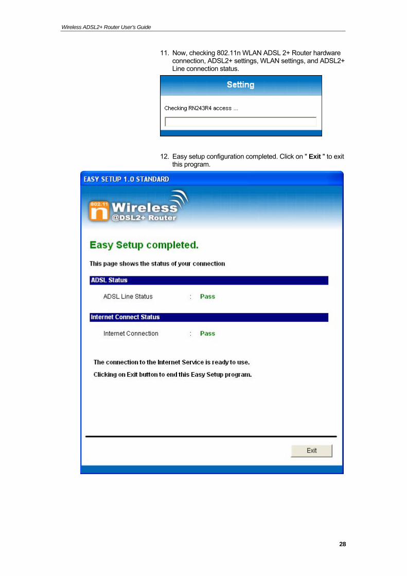
11. Now, checking 802.11n WLAN ADSL 2+ Router hardware connection, ADSL2+ settings, WLAN settings, and ADSL2+ Line connection status.
12. Easy setup configuration completed. Click on " Exit " to exit this program.
28
Wireless ADSL2+ Router User’s Guide
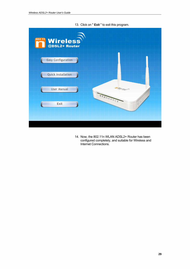
13. Click on " Exit " to exit this program.
14. Now, the 802.11n WLAN ADSL2+ Router has been configured completely, and suitable for Wireless and Internet Connections.
29
Wireless ADSL2+ Router User’s Guide
Wireless Connection
For easy installation it is saved to keep the settings. You can later change the wireless settings via the wireless configuration menu. (see user manual on the CD – Chapter 13 and other).
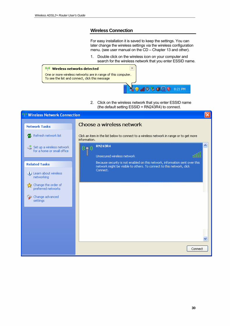
1. Double click on the wireless icon on your computer and search for the wireless network that you enter ESSID name.
2. Click on the wireless network that you enter ESSID name (the default setting ESSID = RN243R4) to connect.
30
Wireless ADSL2+ Router User’s Guide
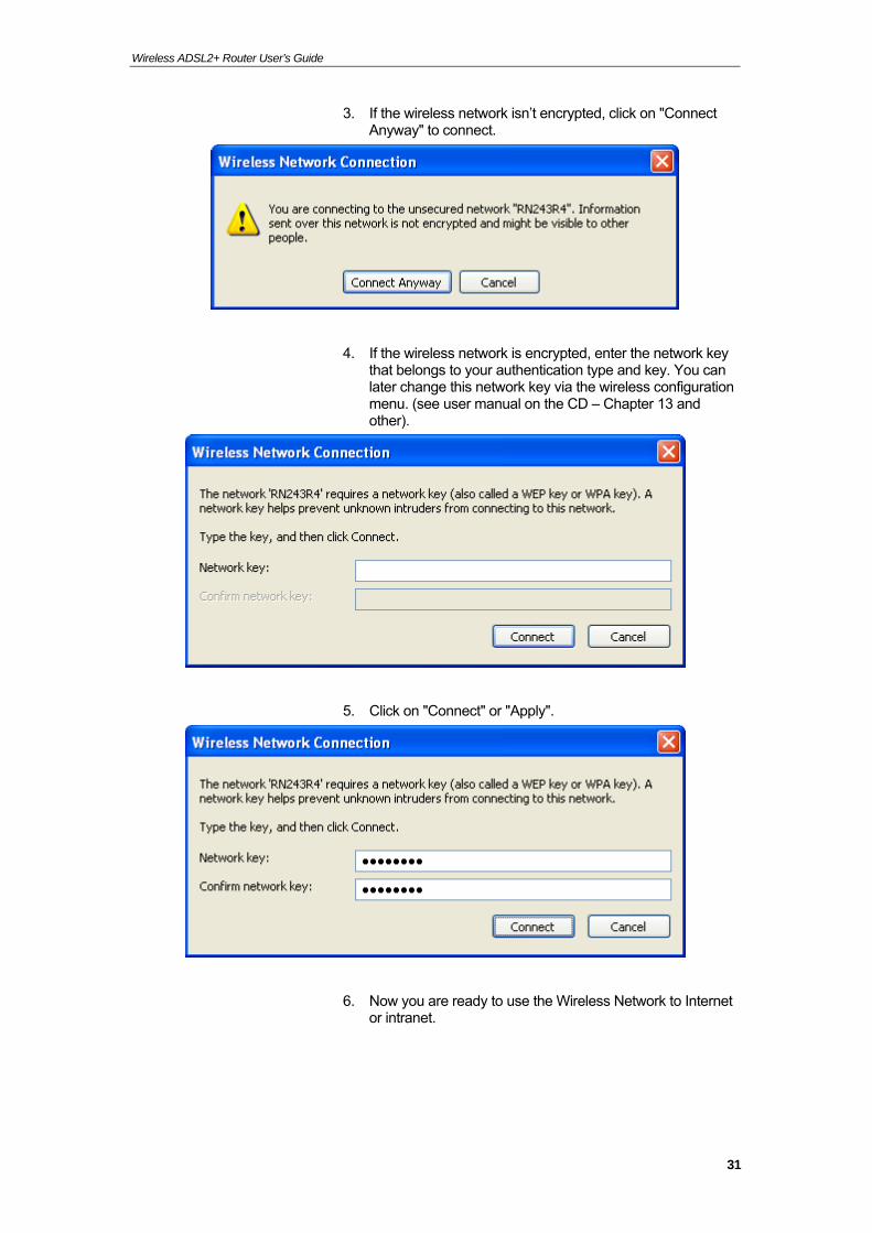
3. If the wireless network isn’t encrypted, click on "Connect Anyway" to connect.
4. If the wireless network is encrypted, enter the network key that belongs to your authentication type and key. You can later change this network key via the wireless configuration menu. (see user manual on the CD – Chapter 13 and other).
5. Click on "Connect" or "Apply".
6. Now you are ready to use the Wireless Network to Internet or intranet.
31
Wireless ADSL2+ Router User’s Guide
5 Getting Started with the Web pages
The Wireless ADSL2+ Router includes a series of Web pages that provide an interface to the software installed on the device. It enables you to configure the device settings to meet the needs of your network. You can access it through your web browser from any PC connected to the device via the LAN ports.
Accessing the Web pages
To access the Web pages, you need the following:
A PC or laptop connected to the LAN port on the device.
A web browser installed on the PC. The minimum browser version requirement is Internet Explorer v4 or Netscape v4. For the best display quality, use latest version of Internet Explorer, Netscape or Mozilla Firefox.From any of the LAN computers, launch your web browser, type the following URL in the web address (or location) box, and press [Enter] on your keyboard:
http://192.168.1.1
The Status homepage for the web pages is displayed:
32
Wireless ADSL2+ Router User’s Guide
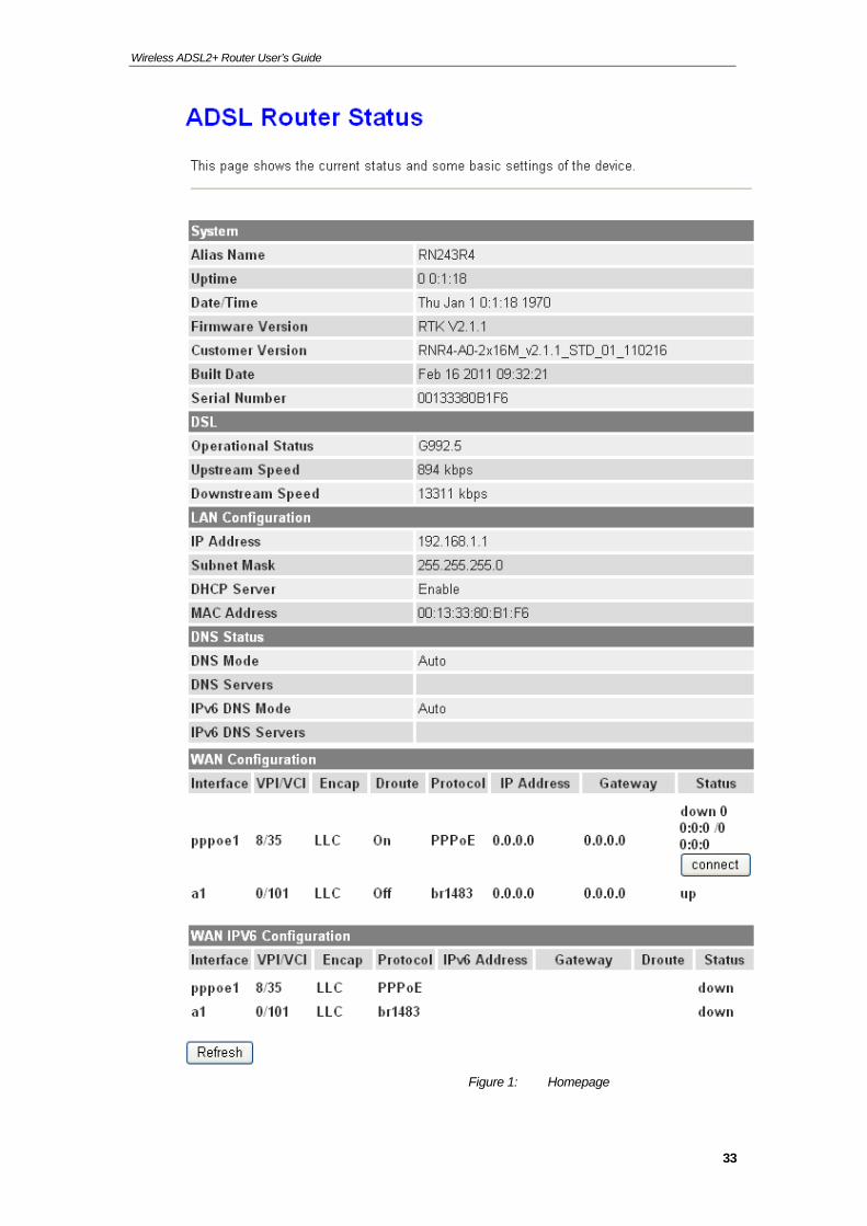
Figure 1: Homepage
33
Wireless ADSL2+ Router User’s Guide
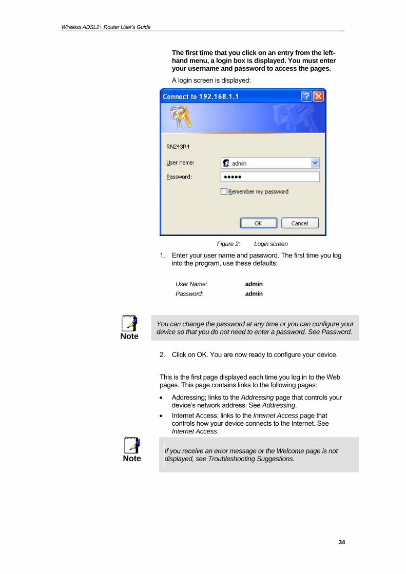
The first time that you click on an entry from the left-hand menu, a login box is displayed. You must enter your username and password to access the pages.
A login screen is displayed:
Figure 2: Login screen
1. Enter your user name and password. The first time you log into the program, use these defaults:
User Name: admin
Password: admin
Note
You can change the password at any time or you can configure your device so that you do not need to enter a password. See Password.
2. Click on OK. You are now ready to configure your device.
This is the first page displayed each time you log in to the Web pages. This page contains links to the following pages:
Addressing; links to the Addressing page that controls your device’s network address. See Addressing.
Internet Access; links to the Internet Access page that controls how your device connects to the Internet. See Internet Access.
Note
If you receive an error message or the Welcome page is not displayed, see Troubleshooting Suggestions.
34
Wireless ADSL2+ Router User’s Guide
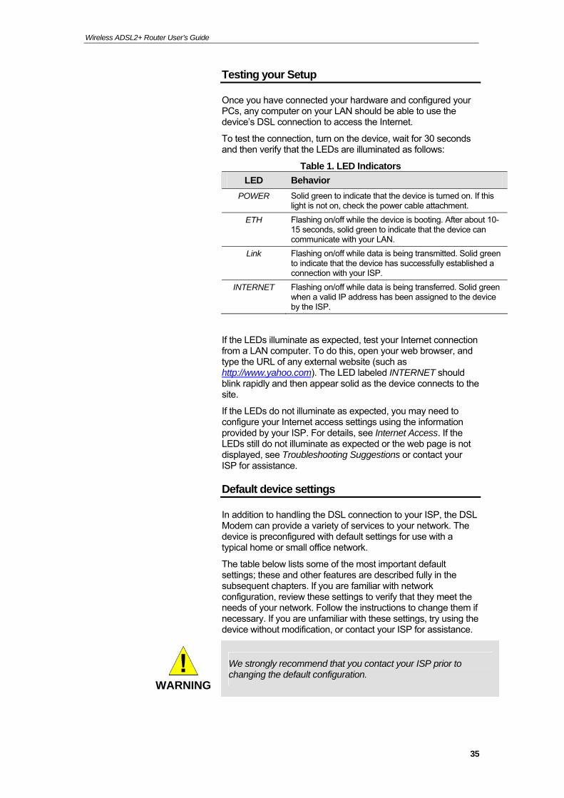
Testing your Setup
Once you have connected your hardware and configured your PCs, any computer on your LAN should be able to use the device’s DSL connection to access the Internet.
To test the connection, turn on the device, wait for 30 seconds and then verify that the LEDs are illuminated as follows:
Table 1. LED Indicators
LED Behavior
POWER Solid green to indicate that the device is turned on. If this light is not on, check the power cable attachment.
ETH Flashing on/off while the device is booting. After about 10-15 seconds, solid green to indicate that the device can communicate with your LAN.
Link Flashing on/off while data is being transmitted. Solid green to indicate that the device has successfully established a connection with your ISP.
INTERNET Flashing on/off while data is being transferred. Solid green when a valid IP address has been assigned to the device by the ISP.
If the LEDs illuminate as expected, test your Internet connection from a LAN computer. To do this, open your web browser, and type the URL of any external website (such as http://www.yahoo.com). The LED labeled INTERNET should blink rapidly and then appear solid as the device connects to the site.
If the LEDs do not illuminate as expected, you may need to configure your Internet access settings using the information provided by your ISP. For details, see Internet Access. If the LEDs still do not illuminate as expected or the web page is not displayed, see Troubleshooting Suggestions or contact your ISP for assistance.
Default device settings
In addition to handling the DSL connection to your ISP, the DSL Modem can provide a variety of services to your network. The device is preconfigured with default settings for use with a typical home or small office network.
The table below lists some of the most important default settings; these and other features are described fully in the subsequent chapters. If you are familiar with network configuration, review these settings to verify that they meet the needs of your network. Follow the instructions to change them if necessary. If you are unfamiliar with these settings, try using the device without modification, or contact your ISP for assistance.
WARNING
We strongly recommend that you contact your ISP prior to changing the default configuration.
35
Wireless ADSL2+ Router User’s Guide
36
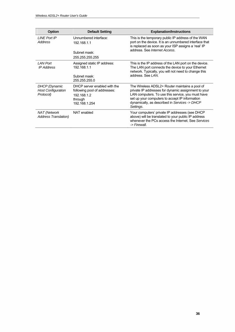
Option Default Setting Explanation/Instructions
LINE Port IP Address
Unnumbered interface: 192.168.1.1 Subnet mask: 255.255.255.255
This is the temporary public IP address of the WAN port on the device. It is an unnumbered interface that is replaced as soon as your ISP assigns a ‘real’ IP address. See Internet Access.
LAN Port IP Address
Assigned static IP address: 192.168.1.1 Subnet mask: 255.255.255.0
This is the IP address of the LAN port on the device. The LAN port connects the device to your Ethernet network. Typically, you will not need to change this address. See LAN.
DHCP (Dynamic Host Configuration Protocol)
DHCP server enabled with the following pool of addresses: 192.168.1.2 through 192.168.1.254
The Wireless ADSL2+ Router maintains a pool of private IP addresses for dynamic assignment to your LAN computers. To use this service, you must have set up your computers to accept IP information dynamically, as described in Services -> DHCP Settings.
NAT (Network Address Translation)
NAT enabled Your computers’ private IP addresses (see DHCP above) will be translated to your public IP address whenever the PCs access the Internet. See Services -> Firewall.

Wireless ADSL2+ Router User’s Guide
6 Overview
The Overview page displays useful information about the setup of your device, including:
details of the device’s Internet access settings
version information about your device
To display this page:
From the head menu, click on Status. The following page is displayed:
37
Wireless ADSL2+ Router User’s Guide
38
Wireless ADSL2+ Router User’s Guide
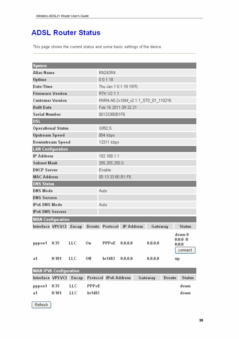
Figure 3: Overview page
The information displayed on this page is explained in detail in the following sections.
Internet access settings
This section displays details of the settings that allow your device to access the Internet. These details include:
IP address and subnet mask:
The IP address and subnet mask assigned to your WAN interface. This address is used temporarily until your ISP assigns a real IP address (via DHCP or PPP – see Internet Access.
Default gateway: The address of the ISP server through which your Internet connection will be routed.
DNS servers: The Domain Name System (DNS) servers used by your ISP to map domain names to IP addresses.
Your ISP assigns all of these settings. In most cases, you will not need to make changes to these settings in order for your Internet connection to work. If your ISP does ask you to change any of these settings, follow the instructions for manually configuring your device in Internet Access.
About Wireless ADSL2+ Router
This section displays details of your device’s hardware and firmware versions. If you need to contact your ISP’s support team, they may need to know which hardware/firmware versions you are using in order to answer your query.
Your hardware version details contain information about the make and model of your device and its exact hardware components.
Your firmware version details contain information about the software program running on your device. From time to time, Chyba! V dokumentu není žádný text v zadaném stylu. may update or add new features to this firmware. They then make the latest updated version available to you via the Internet. For details of how to update your firmware, see Admin -> Upgrade Firmware.
39
Wireless ADSL2+ Router User’s Guide
7 Status
You can view statistics on the processing of IP packets on the networking interfaces. You will not typically need to view this data, but you may find it helpful when working with your ISP to diagnose network and Internet data transmission problems.
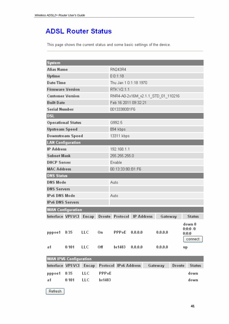
Device Info
This page shows the current status and some basic settings of the device.
1. From the head Status menu, The following page is displayed:
2. To display updated statistics showing any new data since you opened this page, click Refresh.
40
Wireless ADSL2+ Router User’s Guide
41
Wireless ADSL2+ Router User’s Guide
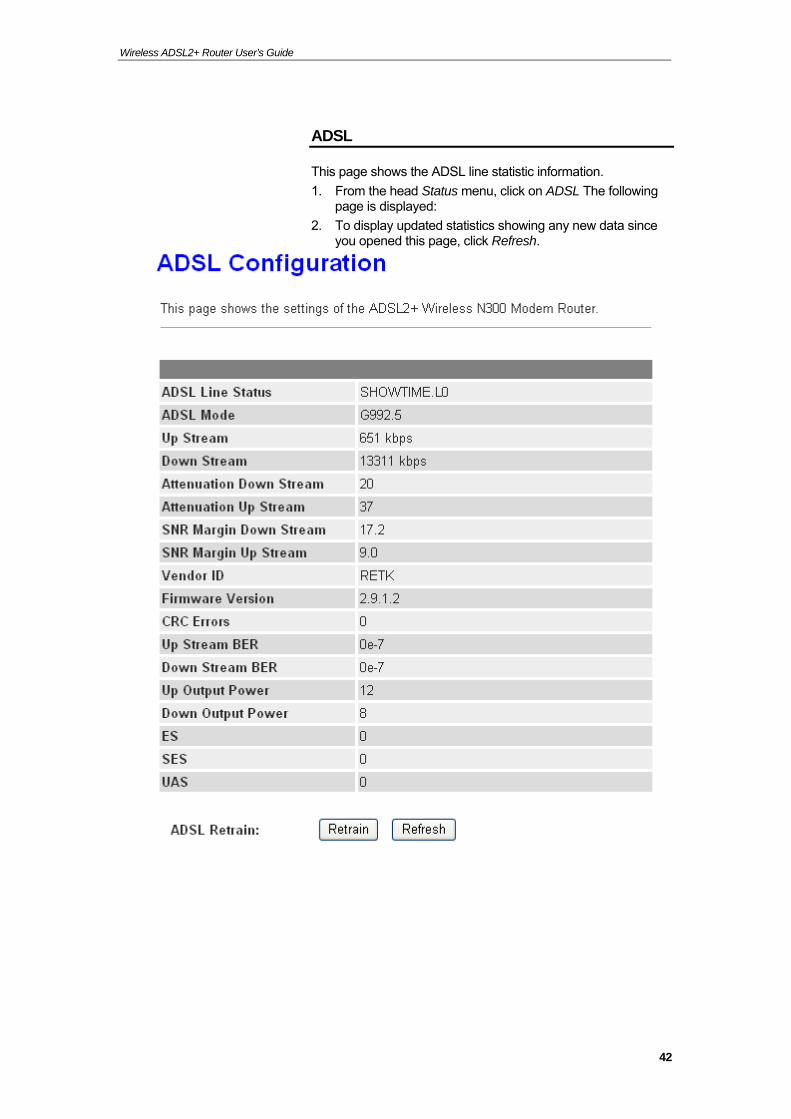
ADSL
This page shows the ADSL line statistic information.
1. From the head Status menu, click on ADSL The following page is displayed:
2. To display updated statistics showing any new data since you opened this page, click Refresh.
42
Wireless ADSL2+ Router User’s Guide
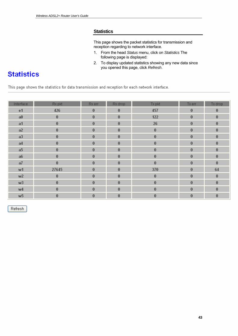
Statistics
This page shows the packet statistics for transmission and reception regarding to network interface.
1. From the head Status menu, click on Statistics The following page is displayed:
2. To display updated statistics showing any new data since you opened this page, click Refresh.
43
Wireless ADSL2+ Router User’s Guide
8 Internet Access
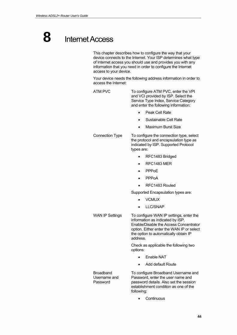
This chapter describes how to configure the way that your device connects to the Internet. Your ISP determines what type of Internet access you should use and provides you with any information that you need in order to configure the Internet access to your device.
Your device needs the following address information in order to access the Internet:
ATM PVC To configure ATM PVC, enter the VPI and VCI provided by ISP. Select the Service Type Index, Service Category and enter the following information:
Peak Cell Rate
Sustainable Cell Rate
Maximum Burst Size
Connection Type To configure the connection type, select the protocol and encapsulation type as indicated by ISP. Supported Protocol types are:
RFC1483 Bridged
RFC1483 MER
PPPoE
PPPoA
RFC1483 Routed
Supported Encapsulation types are:
VCMUX
LLC/SNAP
WAN IP Settings To configure WAN IP settings, enter the information as indicated by ISP. Enable/Disable the Access Concentrator option. Either enter the WAN IP or select the option to automatically obtain IP address.
Check as applicable the following two options:
Enable NAT
Add default Route
Broadband Username and Password
To configure Broadband Username and Password, enter the user name and password details. Also set the session establishment condition as one of the following:
Continuous
44
Wireless ADSL2+ Router User’s Guide
Connect on demand. Enter the minutes after which the session must be disconnected, if no activity takes place.
Manual. Enter the minutes after which the session must be disconnected, if no activity takes place.
In most cases, you will not need to configure your device with these addresses because your ISP is likely to use an Internet access type which automatically assigns addresses to your device. For more information, see Types of Internet Access.
Types of Internet Access
The types of Internet access available are as follows:
PPP Internet access – your device uses a Point to Point Protocol (PPP) to carry data between your ISP and your computer. To use PPP Internet access, you must enter a PPP login username and password the first time to log on. The IP addresses required to access your ISP’s Internet service are automatically configured.
Your device supports PPPoE (over Ethernet).
PPP Internet access – your device uses a Point to Point Protocol (PPP) to carry data between your ISP and your computer. To use PPP Internet access, you must enter a PPP login username and password the first time to log on. The IP addresses required to access your ISP’s Internet service are automatically configured.
Your device supports PPPoA (over ATM).
Bridged Internet access – your device uses a Bridge mode with your PPPoE Client Software to carry data between your ISP and your computer. To use Bridged Internet access with your PPPoE Client Software, you must enter a PPP login username and password the first time to log on. The IP addresses required to access your ISP’s Internet service are automatically configured.
Your device supports RFC 1483 Bridged Mode).
45
Wireless ADSL2+ Router User’s Guide
Configuring your PPPoE DSL connection
If your ISP’s Internet service uses PPPoE you need to set up a PPP login account. The first time that you login to the Internet, your ISP will ask you to enter a username and password so they can check that you are a legitimate, registered Internet service user. Your device stores these authentication details, so you will not have to enter this username and password every time you login.
Your ISP may also tell you to set unique path and circuit numbers (called VPI and VCI) in order to connect your device to the ISP’s Internet service. In most cases, your device will use default settings, so you may not need to enter these values.
Note
Your ISP will provide you with the login details and VPI/VCI values necessary to set up a PPP login account.
If your ISP wants you to connect to the Internet using PPP, follow the instructions below.
46
Wireless ADSL2+ Router User’s Guide
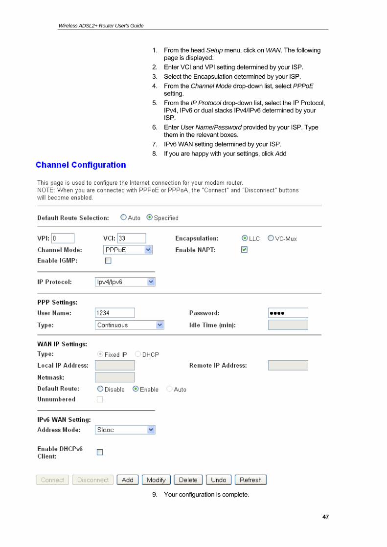
1. From the head Setup menu, click on WAN. The following page is displayed:
2. Enter VCI and VPI setting determined by your ISP.
3. Select the Encapsulation determined by your ISP.
4. From the Channel Mode drop-down list, select PPPoE setting.
5. From the IP Protocol drop-down list, select the IP Protocol, IPv4, IPv6 or dual stacks IPv4/IPv6 determined by your ISP.
6. Enter User Name/Password provided by your ISP. Type them in the relevant boxes.
7. IPv6 WAN setting determined by your ISP.
8. If you are happy with your settings, click Add
9. Your configuration is complete.
47
Wireless ADSL2+ Router User’s Guide
10. Now you are ready to Surf the Internet !!!
Configuring your PPPoA DSL connection
If your ISP’s Internet service uses PPPoA you need to set up a PPP login account. The first time that you login to the Internet, your ISP will ask you to enter a username and password so they can check that you are a legitimate, registered Internet service user. Your device stores these authentication details, so you will not have to enter this username and password every time you login.
Your ISP may also tell you to set unique path and circuit numbers (called VPI and VCI) in order to connect your device to the ISP’s Internet service. In most cases, your device will use default settings, so you may not need to enter these values.
Note
Your ISP will provide you with the login details and VPI/VCI values necessary to set up a PPP login account.
If your ISP wants you to connect to the Internet using PPP, follow the instructions below.
48
Wireless ADSL2+ Router User’s Guide
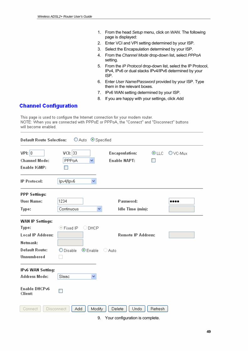
1. From the head Setup menu, click on WAN. The following page is displayed:
2. Enter VCI and VPI setting determined by your ISP.
3. Select the Encapsulation determined by your ISP.
4. From the Channel Mode drop-down list, select PPPoA setting.
5. From the IP Protocol drop-down list, select the IP Protocol, IPv4, IPv6 or dual stacks IPv4/IPv6 determined by your ISP.
6. Enter User Name/Password provided by your ISP. Type them in the relevant boxes.
7. IPv6 WAN setting determined by your ISP.
8. If you are happy with your settings, click Add
9. Your configuration is complete.
49
Wireless ADSL2+ Router User’s Guide
10. Now you are ready to Surf the Internet !!!
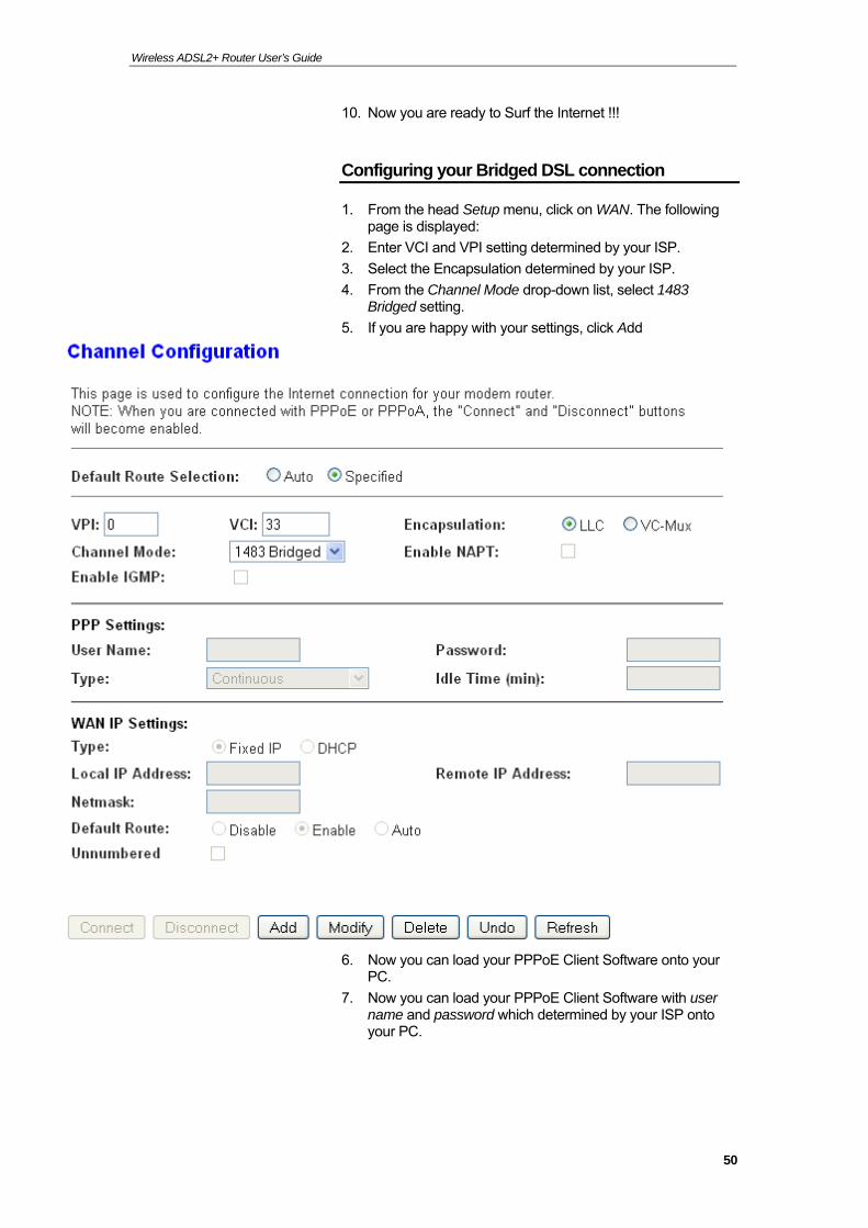
Configuring your Bridged DSL connection
1. From the head Setup menu, click on WAN. The following page is displayed:
2. Enter VCI and VPI setting determined by your ISP.
3. Select the Encapsulation determined by your ISP.
4. From the Channel Mode drop-down list, select 1483 Bridged setting.
5. If you are happy with your settings, click Add
6. Now you can load your PPPoE Client Software onto your PC.
7. Now you can load your PPPoE Client Software with user name and password which determined by your ISP onto your PC.
50
Wireless ADSL2+ Router User’s Guide
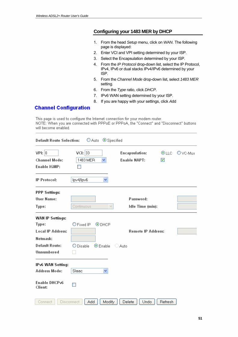
Configuring your 1483 MER by DHCP
1. From the head Setup menu, click on WAN. The following page is displayed:
2. Enter VCI and VPI setting determined by your ISP.
3. Select the Encapsulation determined by your ISP.
4. From the IP Protocol drop-down list, select the IP Protocol, IPv4, IPv6 or dual stacks IPv4/IPv6 determined by your ISP.
5. From the Channel Mode drop-down list, select 1483 MER setting.
6. From the Type ratio, click DHCP.
7. IPv6 WAN setting determined by your ISP.
8. If you are happy with your settings, click Add
51
Wireless ADSL2+ Router User’s Guide
9. Your configuration is complete.
10. Now you are ready to Surf the Internet !!!
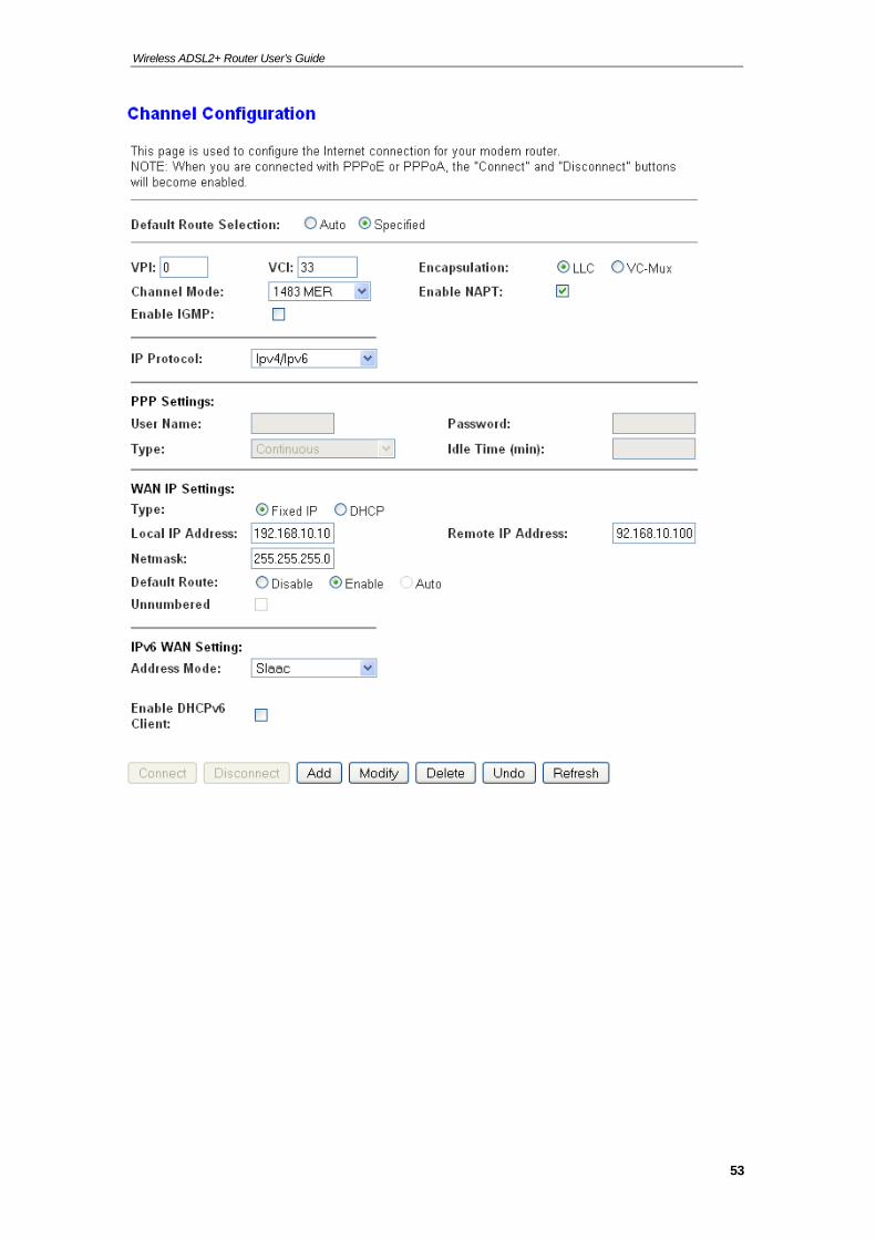
Configuring your 1483 MER by Fixed IP
1. From the head Setup menu, click on WAN. The following page is displayed:
2. Enter VCI and VPI setting determined by your ISP.
3. Select the Encapsulation determined by your ISP.
4. From the Channel Mode drop-down list, select 1483 MER setting.
5. From the IP Protocol drop-down list, select the IP Protocol, IPv4, IPv6 or dual stacks IPv4/IPv6 determined by your ISP.
6. From the Type ratio, click Fixed IP.
7. Enter Local IP Address, Subnet Mask and Remote IP Address which was given by Telecom or by your Internet Service Provider (ISP).
8. IPv6 WAN setting determined by your ISP.
9. If you are happy with your settings, click Add
52
Wireless ADSL2+ Router User’s Guide
53

Wireless ADSL2+ Router User’s Guide
10. From the head Service menu, click on DNS.
11. Check on Set DNS Manually ratio.
12. Enter DNS setting determined by your ISP.
13. Click Apply Changes button.
14. Your configuration is complete.
15. Now you are ready to Surf the Internet !!!
ATM Settings
The page is for ATM PVC QoS parameters setting. The DSL device support 4 QoS mode —CBR/rt-VBR/nrt-VBR/UBR.
1. From the left-hand WAN menu, click on ATM. The following page is displayed:
54

Wireless ADSL2+ Router User’s Guide
Field Description
VPI Virtual Path Identifier. This is read-only field and is selected on the Select column in the Current ATM VC Table.
VCI Virtual Channel Identifier. This is read-only field and is selected on the Select column in the Current ATM VC Table. The VCI, together with VPI, is used to identify the next destination of a cell as it passes through to the ATM switch.
QoS Quality of Server, a characteristic of data transmission that measures how accurately and how quickly a message or data is transferred from a source host to a destination host over a network. The four QoS options are: −UBR (Unspecified Bit Rate): When UBR is selected, the SCR and MBS fields are disabled. −CBR (Constant Bit Rate): When CBR is selected, the SCR and MBS fields are disabled. −nrt-VBR (non-real-time Variable Bit Rate): When nrt-VBR is selected, the SCR and MBS fields are enabled. −rt-VBR (real-time Variable Bit Rate): When rt-VBR is selected, the SCR and MBS fields are enabled.
PCR Peak Cell Rate, measured in cells/sec., is the cell rate which the source may never exceed.
SCR Sustained Cell Rate, measured in cells/sec., is the average cell rate over the duration of the connection.
MBS Maximum Burst Size, a traffic parameter that specifies the maximum number of cells that can be transmitted at the peak cell rate.
Function Button Description
Apply Changes Set new PVC OoS mode for the selected PVC. New parameters will take effect after save into flash memory and reboot the system. See section “Admin” for save details.
Undo Discard your settings.
55
Wireless ADSL2+ Router User’s Guide
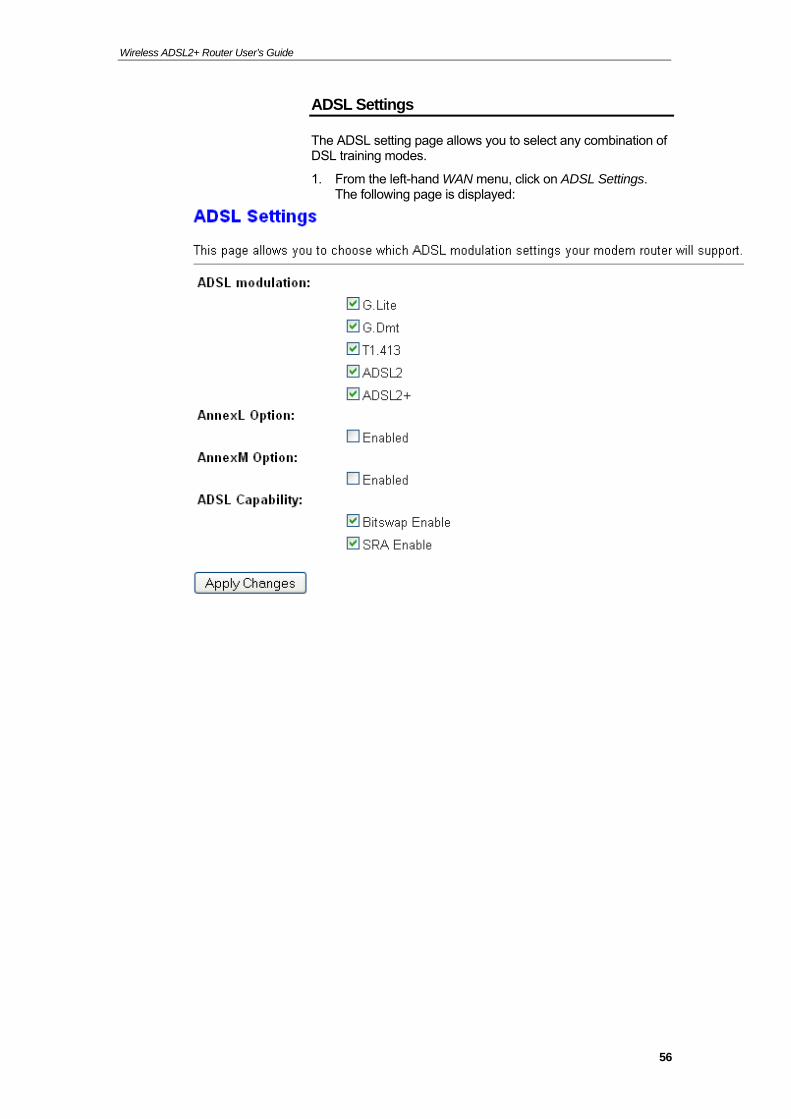
ADSL Settings
The ADSL setting page allows you to select any combination of DSL training modes.
1. From the left-hand WAN menu, click on ADSL Settings. The following page is displayed:
56
Wireless ADSL2+ Router User’s Guide
57
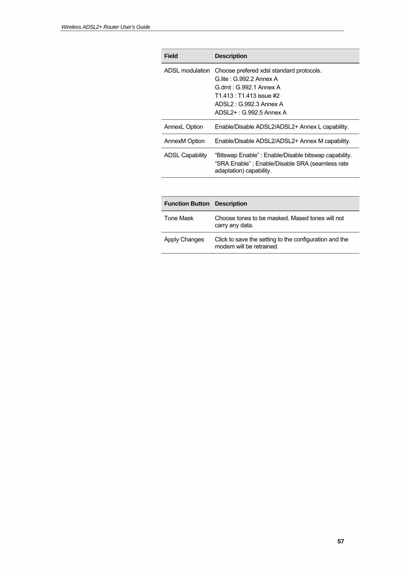
Field Description
ADSL modulation Choose prefered xdsl standard protocols. G.lite : G.992.2 Annex A G.dmt : G.992.1 Annex A T1.413 : T1.413 issue #2 ADSL2 : G.992.3 Annex A ADSL2+ : G.992.5 Annex A
AnnexL Option Enable/Disable ADSL2/ADSL2+ Annex L capability.
AnnexM Option Enable/Disable ADSL2/ADSL2+ Annex M capability.
ADSL Capability “Bitswap Enable” : Enable/Disable bitswap capability. “SRA Enable” : Enable/Disable SRA (seamless rate adaptation) capability.
Function Button Description
Tone Mask Choose tones to be masked. Mased tones will not carry any data.
Apply Changes Click to save the setting to the configuration and the modem will be retrained.

User’s Guide Configuring your Computers
9 Local Network Configuration
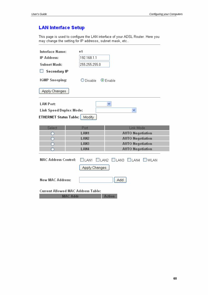
The Addressing page displays information about your LAN IP address and allows you to change the address and subnet mask assigned to your device.
Note
You should only change the addressing details if your ISP asks you to, or if you are familiar with network configuration. In most cases, you will not need to make any changes to this configuration.
Changing the LAN IP address and subnet mask
1. From the head Setup menu, click on LAN. The following page is displayed:
59
User’s Guide Configuring your Computers
60
User’s Guide Configuring your Computers
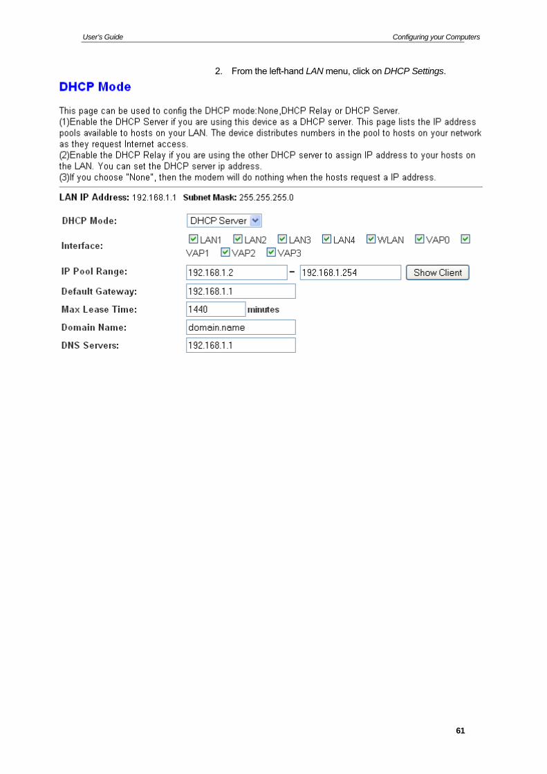
2. From the left-hand LAN menu, click on DHCP Settings.
61
User’s Guide Configuring your Computers
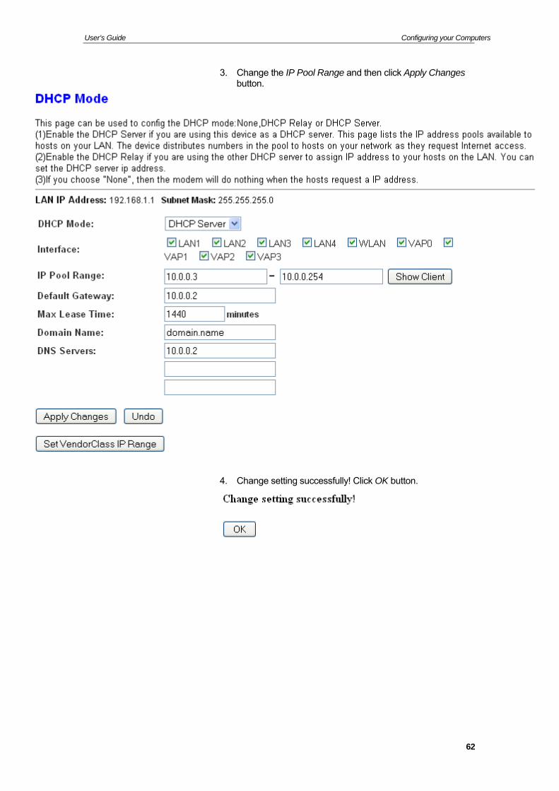
3. Change the IP Pool Range and then click Apply Changes button.
4. Change setting successfully! Click OK button.
62
User’s Guide Configuring your Computers
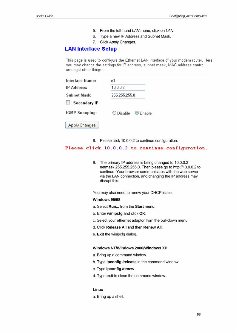
5. From the left-hand LAN menu, click on LAN.
6. Type a new IP Address and Subnet Mask.
7. Click Apply Changes.
8. Please click 10.0.0.2 to continue configuration.
9. The primary IP address is being changed to 10.0.0.2 netmask 255.255.255.0. Then please go to http://10.0.0.2 to continue. Your browser communicates with the web server via the LAN connection, and changing the IP address may disrupt this.
You may also need to renew your DHCP lease:
Windows 95/98
a. Select Run... from the Start menu.
b. Enter winipcfg and click OK.
c. Select your ethernet adaptor from the pull-down menu
d. Click Release All and then Renew All.
e. Exit the winipcfg dialog.
Windows NT/Windows 2000/Windows XP
a. Bring up a command window.
b. Type ipconfig /release in the command window.
c. Type ipconfig /renew.
d. Type exit to close the command window.
Linux
a. Bring up a shell.
63
User’s Guide Configuring your Computers
b. Type pump -r to release the lease.
c. Type pump to renew the lease.
Note
If you change the LAN IP address of the device while connected through your Web browser, you will be disconnected. You must open a new connection by entering your new LAN IP address as the URL.
10. From the left-hand menu, click on Save.
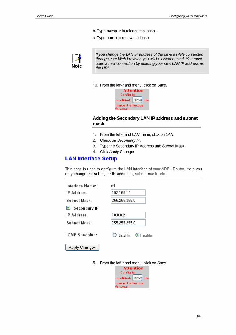
Adding the Secondary LAN IP address and subnet mask
1. From the left-hand LAN menu, click on LAN.
2. Check on Secondary IP.
3. Type the Secondary IP Address and Subnet Mask.
4. Click Apply Changes.
5. From the left-hand menu, click on Save.
64
User’s Guide Configuring your Computers
10 DHCP Settings
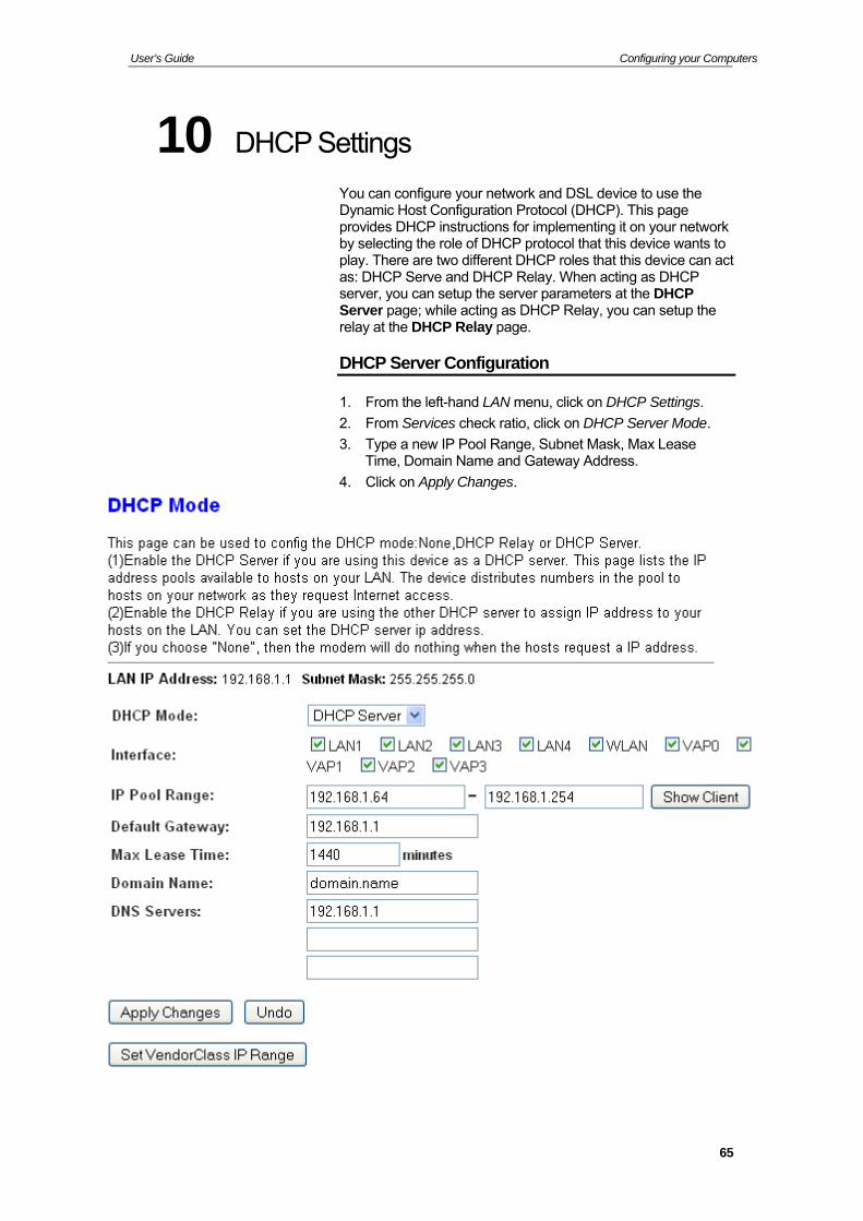
You can configure your network and DSL device to use the Dynamic Host Configuration Protocol (DHCP). This page provides DHCP instructions for implementing it on your network by selecting the role of DHCP protocol that this device wants to play. There are two different DHCP roles that this device can act as: DHCP Serve and DHCP Relay. When acting as DHCP server, you can setup the server parameters at the DHCP Server page; while acting as DHCP Relay, you can setup the relay at the DHCP Relay page.
DHCP Server Configuration
1. From the left-hand LAN menu, click on DHCP Settings.
2. From Services check ratio, click on DHCP Server Mode.
3. Type a new IP Pool Range, Subnet Mask, Max Lease Time, Domain Name and Gateway Address.
4. Click on Apply Changes.
65
User’s Guide Configuring your Computers
Field Description
IP Pool Range Specify the lowest and highest addresses in the pool.
Max Lease Time The Lease Time is the amount of time that a network user is allowed to maintain a network connection to the device using the current dynamic IP address. At the end of the Lease Time, the lease is either renewed or a new IP is issued by the DHCP server. The amount of time is in units of seconds. The default value is 86400 seconds (1 day). The value –1 stands for the infinite lease.
Domain Name A user-friendly name that refers to the group of hosts (subnet) that will be assigned addresses from this pool.
Function Button Description
Show Client This shows the assigned IP address, MAC address and time expired for each DHCP leased client.
Apply Changes Set new DHCP server configuration. New parameters will take effect after save into flash memory and reboot the system. See section “Admin” for save details.
Undo Discard your changes.
5. From the left-hand menu, click on Save.
66
User’s Guide Configuring your Computers
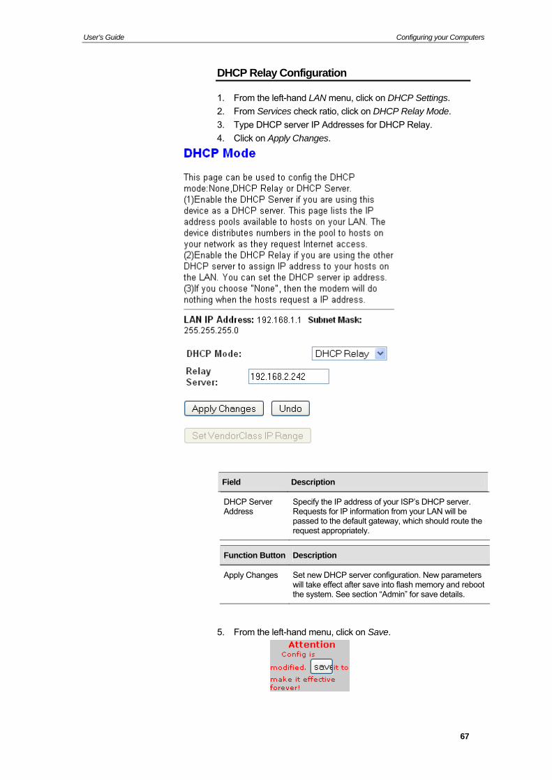
DHCP Relay Configuration
1. From the left-hand LAN menu, click on DHCP Settings.
2. From Services check ratio, click on DHCP Relay Mode.
3. Type DHCP server IP Addresses for DHCP Relay.
4. Click on Apply Changes.
Field Description
DHCP Server Address
Specify the IP address of your ISP’s DHCP server. Requests for IP information from your LAN will be passed to the default gateway, which should route the request appropriately.
Function Button Description
Apply Changes Set new DHCP server configuration. New parameters will take effect after save into flash memory and reboot the system. See section “Admin” for save details.
5. From the left-hand menu, click on Save.
67
User’s Guide Configuring your Computers
6. You need to renew your DHCP lease:
Windows 95/98
a. Select Run... from the Start menu.
b. Enter winipcfg and click OK.
c. Select your ethernet adaptor from the pull-down menu
d. Click Release All and then Renew All.
e. Exit the winipcfg dialog.
Windows NT/Windows 2000/Windows XP
a. Bring up a command window.
b. Type ipconfig /release in the command window.
c. Type ipconfig /renew.
d. Type exit to close the command window.
Linux
a. Bring up a shell.
b. Type pump -r to release the lease.
c. Type pump to renew the lease.
68
User’s Guide Configuring your Computers
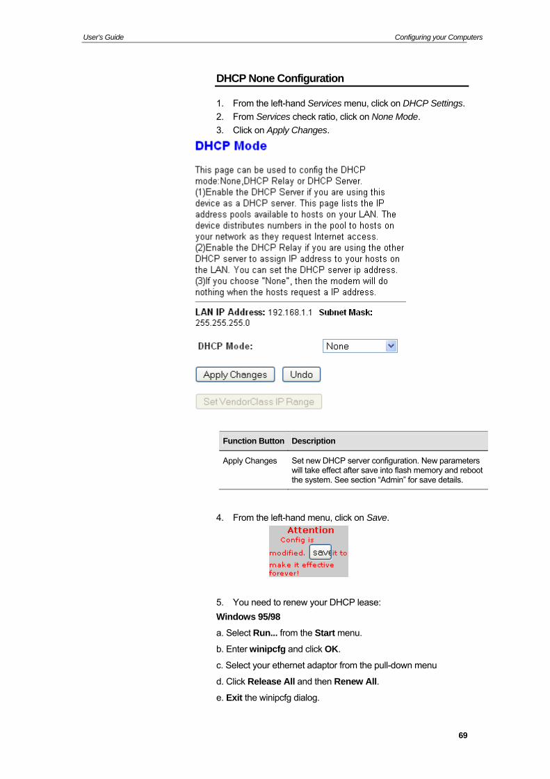
DHCP None Configuration
1. From the left-hand Services menu, click on DHCP Settings.
2. From Services check ratio, click on None Mode.
3. Click on Apply Changes.
Function Button Description
Apply Changes Set new DHCP server configuration. New parameters will take effect after save into flash memory and reboot the system. See section “Admin” for save details.
4. From the left-hand menu, click on Save.
5. You need to renew your DHCP lease:
Windows 95/98
a. Select Run... from the Start menu.
b. Enter winipcfg and click OK.
c. Select your ethernet adaptor from the pull-down menu
d. Click Release All and then Renew All.
e. Exit the winipcfg dialog.
69
User’s Guide Configuring your Computers
Windows NT/Windows 2000/Windows XP
a. Bring up a command window.
b. Type ipconfig /release in the command window.
c. Type ipconfig /renew.
d. Type exit to close the command window.
Linux
a. Bring up a shell.
b. Type pump -r to release the lease.
c. Type pump to renew the lease.
6. From the left-hand Admin menu, click on Commit/Reboot. The following page is displayed:
70
User’s Guide Configuring your Computers
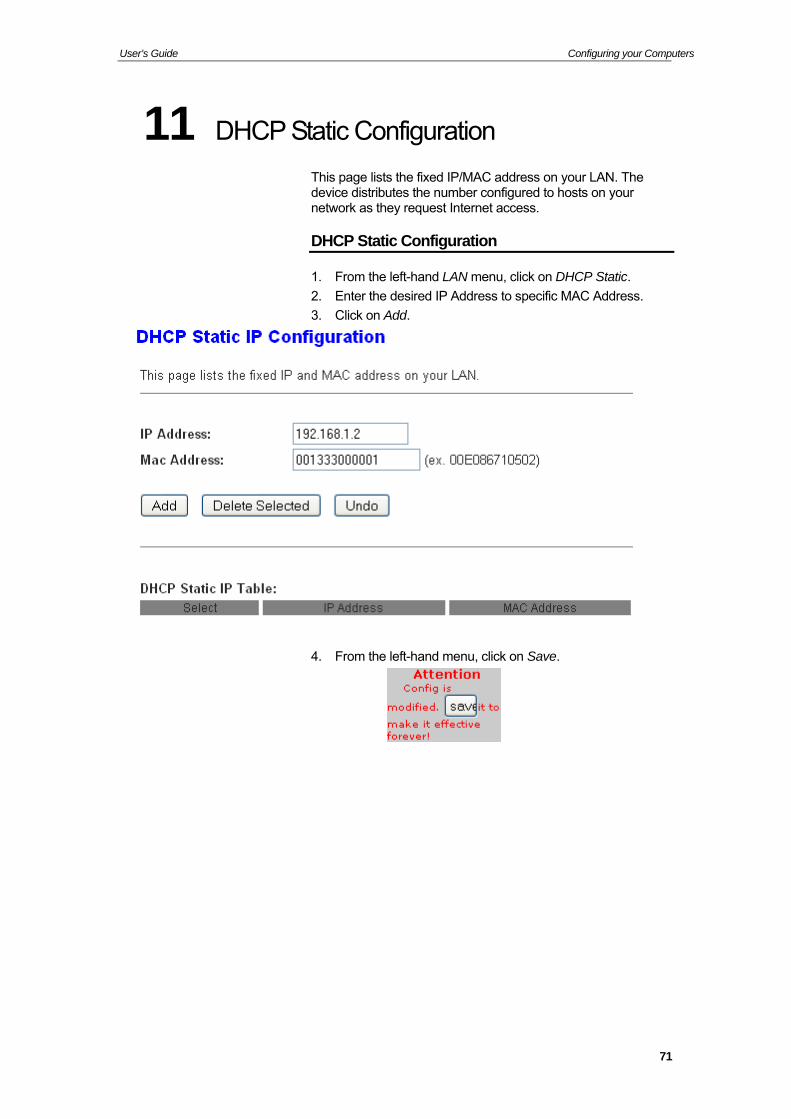
11 DHCP Static Configuration
This page lists the fixed IP/MAC address on your LAN. The device distributes the number configured to hosts on your network as they request Internet access.
DHCP Static Configuration
1. From the left-hand LAN menu, click on DHCP Static.
2. Enter the desired IP Address to specific MAC Address.
3. Click on Add.
4. From the left-hand menu, click on Save.
71
User’s Guide Configuring your Computers
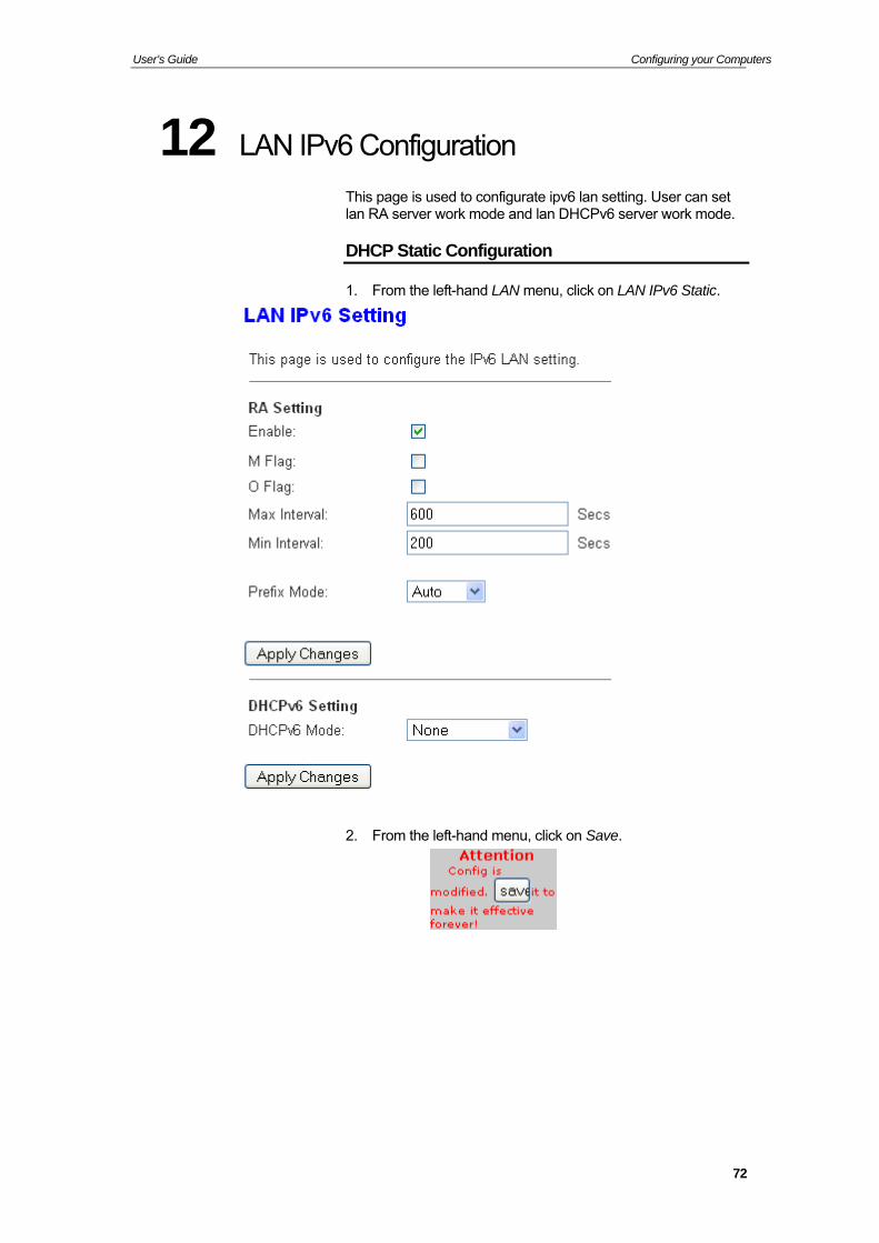
12 LAN IPv6 Configuration
This page is used to configurate ipv6 lan setting. User can set lan RA server work mode and lan DHCPv6 server work mode.
DHCP Static Configuration
1. From the left-hand LAN menu, click on LAN IPv6 Static.
2. From the left-hand menu, click on Save.
72
User’s Guide Configuring your Computers
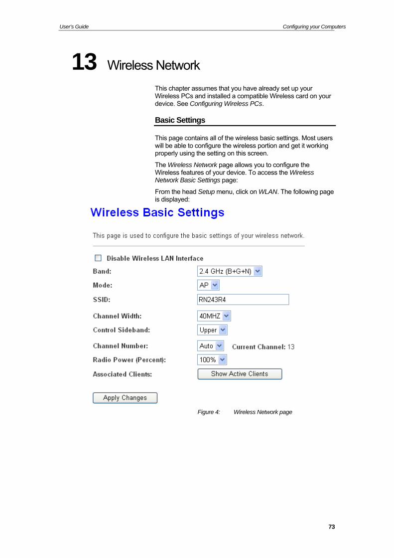
13 Wireless Network
This chapter assumes that you have already set up your Wireless PCs and installed a compatible Wireless card on your device. See Configuring Wireless PCs.
Basic Settings
This page contains all of the wireless basic settings. Most users will be able to configure the wireless portion and get it working properly using the setting on this screen.
The Wireless Network page allows you to configure the Wireless features of your device. To access the Wireless Network Basic Settings page:
From the head Setup menu, click on WLAN. The following page is displayed:
Figure 4: Wireless Network page
73
User’s Guide Configuring your Computers
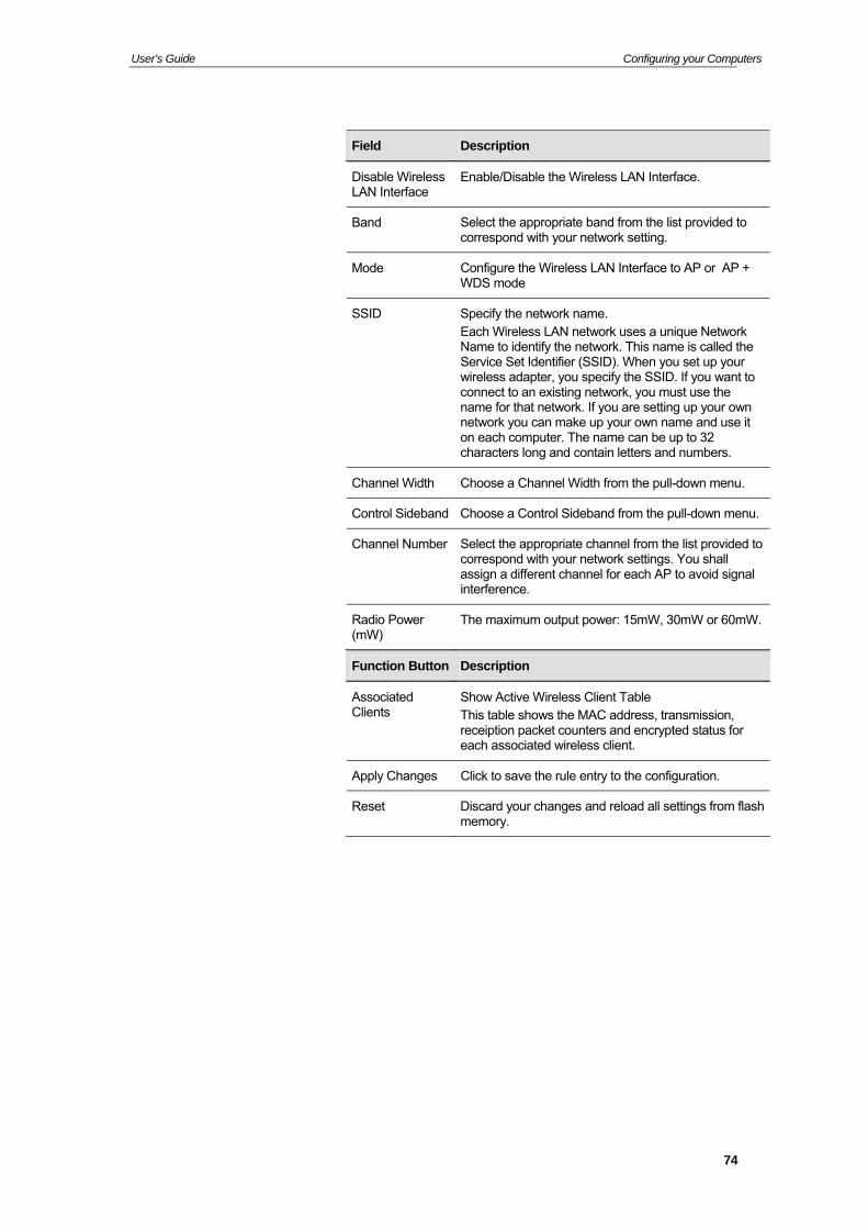
Field Description
Disable Wireless LAN Interface
Enable/Disable the Wireless LAN Interface.
Band Select the appropriate band from the list provided to correspond with your network setting.
Mode Configure the Wireless LAN Interface to AP or AP + WDS mode
SSID Specify the network name. Each Wireless LAN network uses a unique Network Name to identify the network. This name is called the Service Set Identifier (SSID). When you set up your wireless adapter, you specify the SSID. If you want to connect to an existing network, you must use the name for that network. If you are setting up your own network you can make up your own name and use it on each computer. The name can be up to 32 characters long and contain letters and numbers.
Channel Width Choose a Channel Width from the pull-down menu.
Control Sideband Choose a Control Sideband from the pull-down menu.
Channel Number Select the appropriate channel from the list provided to correspond with your network settings. You shall assign a different channel for each AP to avoid signal interference.
Radio Power (mW)
The maximum output power: 15mW, 30mW or 60mW.
Function Button Description
Associated Clients
Show Active Wireless Client Table This table shows the MAC address, transmission, receiption packet counters and encrypted status for each associated wireless client.
Apply Changes Click to save the rule entry to the configuration.
Reset Discard your changes and reload all settings from flash memory.
74
User’s Guide Configuring your Computers
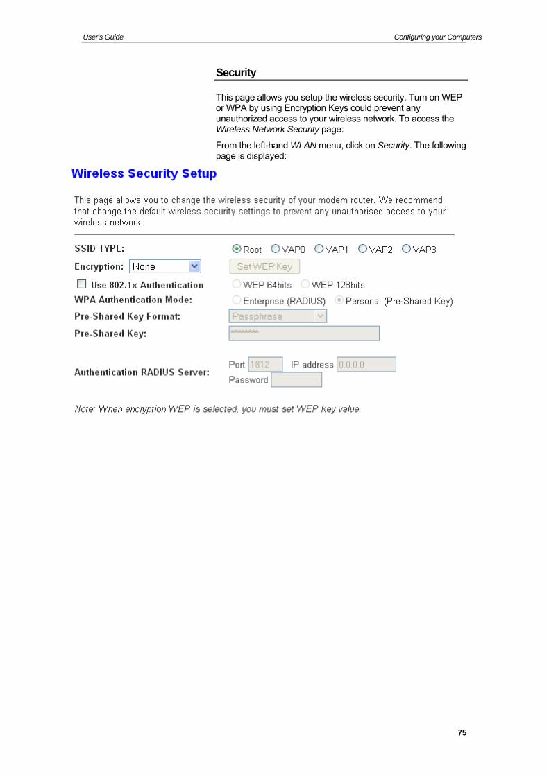
Security
This page allows you setup the wireless security. Turn on WEP or WPA by using Encryption Keys could prevent any unauthorized access to your wireless network. To access the Wireless Network Security page:
From the left-hand WLAN menu, click on Security. The following page is displayed:
75
User’s Guide Configuring your Computers
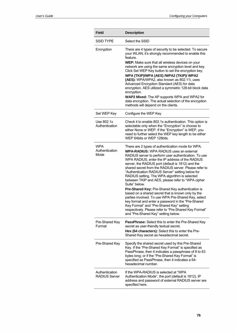
Field Description
SSID TYPE Select the SSID
Encryption There are 4 types of security to be selected. To secure your WLAN, it’s strongly recommended to enable this feature. WEP: Make sure that all wireless devices on your network are using the same encryption level and key. Click Set WEP Key button to set the encryption key. WPA (TKIP)/WPA (AES) /WPA2 (TKIP)/ WPA2 (AES): WPA/WPA2, also known as 802.11i, uses Advanced Encryption Standard (AES) for data encryption. AES utilized a symmetric 128-bit block data encryption. WAP2 Mixed: The AP supports WPA and WPA2 for data encryption. The actual selection of the encryption methods will depend on the clients.
Set WEP Key Configure the WEP Key
Use 802.1x Authentication
Check it to enable 802.1x authentication. This option is selectable only when the “Encryption” is choose to either None or WEP. If the “Encryption” is WEP, you need to further select the WEP key length to be either WEP 64bits or WEP 128bits.
WPA Authentication Mode
There are 2 types of authentication mode for WPA. WPA-RADIUS: WPA RADIUS uses an external RADIUS server to perform user authentication. To use WPA RADIUS, enter the IP address of the RADIUS server, the RADIUS port (default is 1812) and the shared secret from the RADIUS server. Please refer to “Authentication RADIUS Server” setting below for RADIUS setting. The WPA algorithm is selected between TKIP and AES, please refer to “WPA cipher Suite” below. Pre-Shared Key: Pre-Shared Key authentication is based on a shared secret that is known only by the parties involved. To use WPA Pre-Shared Key, select key format and enter a password in the “Pre-Shared Key Format” and “Pre-Shared Key” setting respectively. Please refer to “Pre-Shared Key Format” and “Pre-Shared Key” setting below.
Pre-Shared Key Format
PassPhrase: Select this to enter the Pre-Shared Key secret as user-friendly textual secret. Hex (64 characters): Select this to enter the Pre-Shared Key secret as hexadecimal secret.
Pre-Shared Key Specify the shared secret used by this Pre-Shared Key. If the “Pre-Shared Key Format” is specified as PassPhrase, then it indicates a passphrase of 8 to 63 bytes long; or if the “Pre-Shared Key Format” is specified as PassPhrase, then it indicates a 64-hexadecimal number.
Authentication RADIUS Server
If the WPA-RADIUS is selected at “WPA Authentication Mode”, the port (default is 1812), IP address and password of external RADIUS server are specified here.
76
User’s Guide Configuring your Computers
Function Button Description
Apply Changes Click to save the rule entry to the configuration.
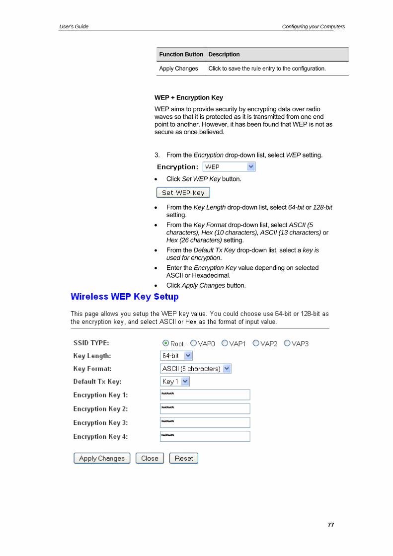
WEP + Encryption Key
WEP aims to provide security by encrypting data over radio waves so that it is protected as it is transmitted from one end point to another. However, it has been found that WEP is not as secure as once believed.
3. From the Encryption drop-down list, select WEP setting.
Click Set WEP Key button.
From the Key Length drop-down list, select 64-bit or 128-bit
setting.
From the Key Format drop-down list, select ASCII (5 characters), Hex (10 characters), ASCII (13 characters) or Hex (26 characters) setting.
From the Default Tx Key drop-down list, select a key is used for encryption.
Enter the Encryption Key value depending on selected ASCII or Hexadecimal.
Click Apply Changes button.
77
User’s Guide Configuring your Computers
Wlan is restarting! Please wait...
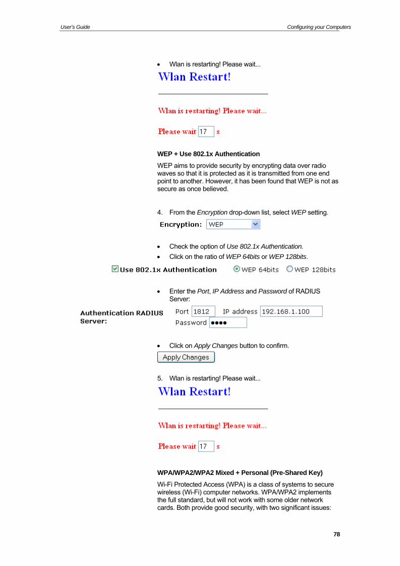
WEP + Use 802.1x Authentication
WEP aims to provide security by encrypting data over radio waves so that it is protected as it is transmitted from one end point to another. However, it has been found that WEP is not as secure as once believed.
4. From the Encryption drop-down list, select WEP setting.
Check the option of Use 802.1x Authentication.
Click on the ratio of WEP 64bits or WEP 128bits.
Enter the Port, IP Address and Password of RADIUS Server:
Click on Apply Changes button to confirm.
5. Wlan is restarting! Please wait...
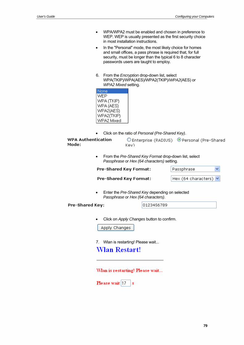
WPA/WPA2/WPA2 Mixed + Personal (Pre-Shared Key)
Wi-Fi Protected Access (WPA) is a class of systems to secure wireless (Wi-Fi) computer networks. WPA/WPA2 implements the full standard, but will not work with some older network cards. Both provide good security, with two significant issues:
78
User’s Guide Configuring your Computers
WPA/WPA2 must be enabled and chosen in preference to WEP. WEP is usually presented as the first security choice in most installation instructions.
In the "Personal" mode, the most likely choice for homes and small offices, a pass phrase is required that, for full security, must be longer than the typical 6 to 8 character passwords users are taught to employ.
6. From the Encryption drop-down list, select WPA(TKIP)/WPA(AES)/WPA2(TKIP)/WPA2(AES) or WPA2 Mixed setting.
Click on the ratio of Personal (Pre-Shared Key).
From the Pre-Shared Key Format drop-down list, select Passphrase or Hex (64 characters) setting.
Enter the Pre-Shared Key depending on selected Passphrase or Hex (64 characters).
Click on Apply Changes button to confirm.
7. Wlan is restarting! Please wait...
79
User’s Guide Configuring your Computers
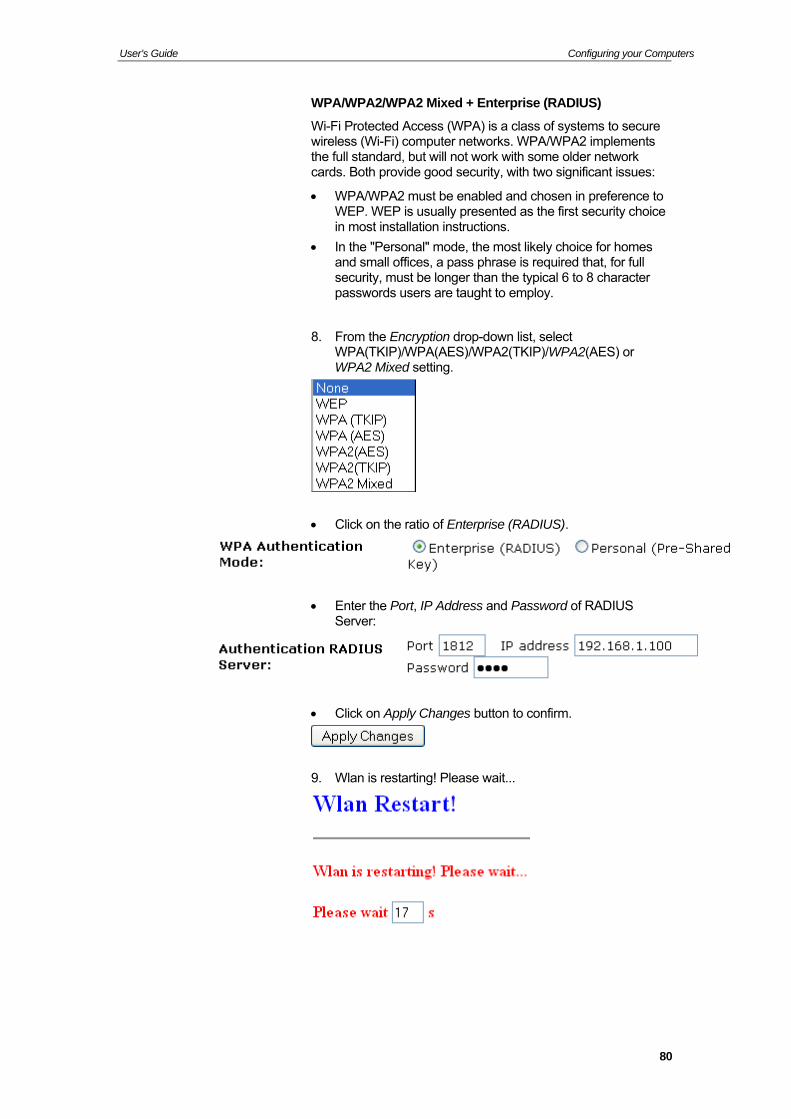
WPA/WPA2/WPA2 Mixed + Enterprise (RADIUS)
Wi-Fi Protected Access (WPA) is a class of systems to secure wireless (Wi-Fi) computer networks. WPA/WPA2 implements the full standard, but will not work with some older network cards. Both provide good security, with two significant issues:
WPA/WPA2 must be enabled and chosen in preference to WEP. WEP is usually presented as the first security choice in most installation instructions.
In the "Personal" mode, the most likely choice for homes and small offices, a pass phrase is required that, for full security, must be longer than the typical 6 to 8 character passwords users are taught to employ.
8. From the Encryption drop-down list, select WPA(TKIP)/WPA(AES)/WPA2(TKIP)/WPA2(AES) or WPA2 Mixed setting.
Click on the ratio of Enterprise (RADIUS).
Enter the Port, IP Address and Password of RADIUS Server:
Click on Apply Changes button to confirm.
9. Wlan is restarting! Please wait...
80

User’s Guide Configuring your Computers
Wireless Multiple BSSID Settings
This page allows you to set Virtual Access Points (VAP). Here you can enable/disable virtual APs and set the SSID and authentication type. Click "Apply Changes" for these settings to take effect.
To access the MBSSID Settings page:
From the left-hand WLAN menu, click on MBSSID. The following page is displayed:
81

User’s Guide Configuring your Computers
82
User’s Guide Configuring your Computers
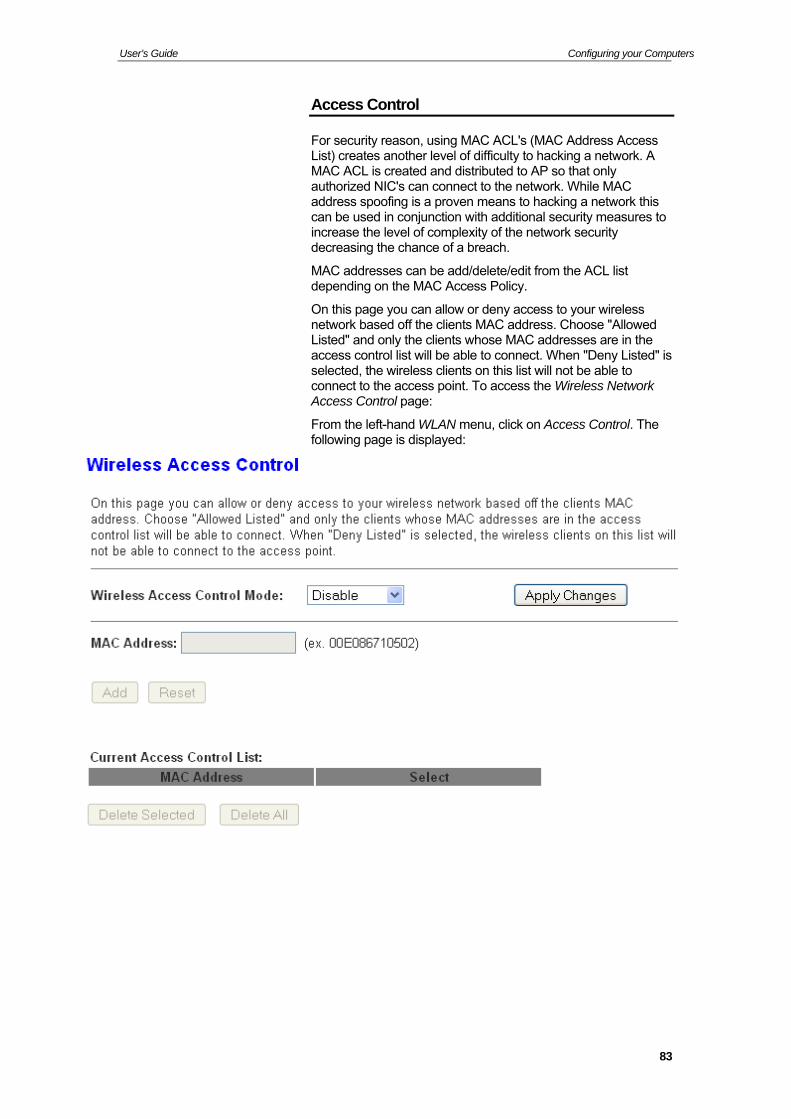
Access Control
For security reason, using MAC ACL's (MAC Address Access List) creates another level of difficulty to hacking a network. A MAC ACL is created and distributed to AP so that only authorized NIC's can connect to the network. While MAC address spoofing is a proven means to hacking a network this can be used in conjunction with additional security measures to increase the level of complexity of the network security decreasing the chance of a breach.
MAC addresses can be add/delete/edit from the ACL list depending on the MAC Access Policy.
On this page you can allow or deny access to your wireless network based off the clients MAC address. Choose "Allowed Listed" and only the clients whose MAC addresses are in the access control list will be able to connect. When "Deny Listed" is selected, the wireless clients on this list will not be able to connect to the access point. To access the Wireless Network Access Control page:
From the left-hand WLAN menu, click on Access Control. The following page is displayed:
83
User’s Guide Configuring your Computers
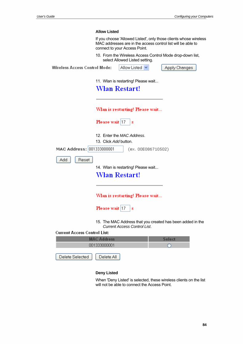
Allow Listed
If you choose 'Allowed Listed', only those clients whose wireless MAC addresses are in the access control list will be able to connect to your Access Point.
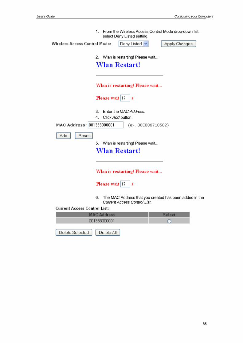
10. From the Wireless Access Control Mode drop-down list, select Allowed Listed setting.
11. Wlan is restarting! Please wait...
12. Enter the MAC Address.
13. Click Add button.
14. Wlan is restarting! Please wait...
15. The MAC Address that you created has been added in the Current Access Control List.
Deny Listed
When 'Deny Listed' is selected, these wireless clients on the list will not be able to connect the Access Point.
84
User’s Guide Configuring your Computers
1. From the Wireless Access Control Mode drop-down list, select Deny Listed setting.
2. Wlan is restarting! Please wait...
3. Enter the MAC Address.
4. Click Add button.
5. Wlan is restarting! Please wait...
6. The MAC Address that you created has been added in the Current Access Control List.
85
User’s Guide Configuring your Computers
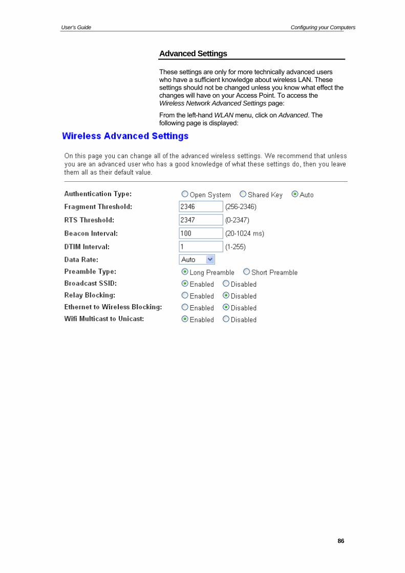
Advanced Settings
These settings are only for more technically advanced users who have a sufficient knowledge about wireless LAN. These settings should not be changed unless you know what effect the changes will have on your Access Point. To access the Wireless Network Advanced Settings page:
From the left-hand WLAN menu, click on Advanced. The following page is displayed:
86
User’s Guide Configuring your Computers
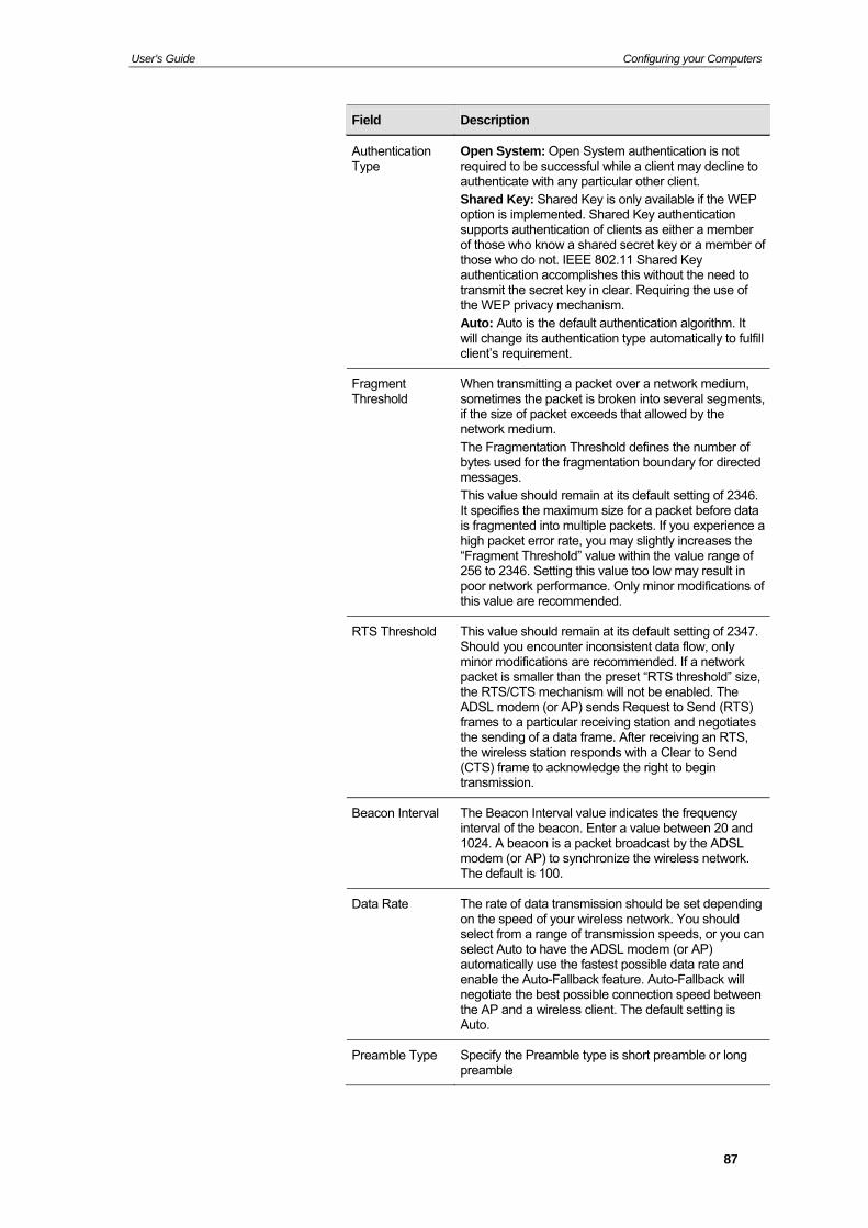
Field Description
Authentication Type
Open System: Open System authentication is not required to be successful while a client may decline to authenticate with any particular other client. Shared Key: Shared Key is only available if the WEP option is implemented. Shared Key authentication supports authentication of clients as either a member of those who know a shared secret key or a member of those who do not. IEEE 802.11 Shared Key authentication accomplishes this without the need to transmit the secret key in clear. Requiring the use of the WEP privacy mechanism. Auto: Auto is the default authentication algorithm. It will change its authentication type automatically to fulfill client’s requirement.
Fragment Threshold
When transmitting a packet over a network medium, sometimes the packet is broken into several segments, if the size of packet exceeds that allowed by the network medium. The Fragmentation Threshold defines the number of bytes used for the fragmentation boundary for directed messages. This value should remain at its default setting of 2346. It specifies the maximum size for a packet before data is fragmented into multiple packets. If you experience a high packet error rate, you may slightly increases the “Fragment Threshold” value within the value range of 256 to 2346. Setting this value too low may result in poor network performance. Only minor modifications of this value are recommended.
RTS Threshold This value should remain at its default setting of 2347. Should you encounter inconsistent data flow, only minor modifications are recommended. If a network packet is smaller than the preset “RTS threshold” size, the RTS/CTS mechanism will not be enabled. The ADSL modem (or AP) sends Request to Send (RTS) frames to a particular receiving station and negotiates the sending of a data frame. After receiving an RTS, the wireless station responds with a Clear to Send (CTS) frame to acknowledge the right to begin transmission.
Beacon Interval The Beacon Interval value indicates the frequency interval of the beacon. Enter a value between 20 and 1024. A beacon is a packet broadcast by the ADSL modem (or AP) to synchronize the wireless network. The default is 100.
Data Rate The rate of data transmission should be set depending on the speed of your wireless network. You should select from a range of transmission speeds, or you can select Auto to have the ADSL modem (or AP) automatically use the fastest possible data rate and enable the Auto-Fallback feature. Auto-Fallback will negotiate the best possible connection speed between the AP and a wireless client. The default setting is Auto.
Preamble Type Specify the Preamble type is short preamble or long preamble
87
User’s Guide Configuring your Computers
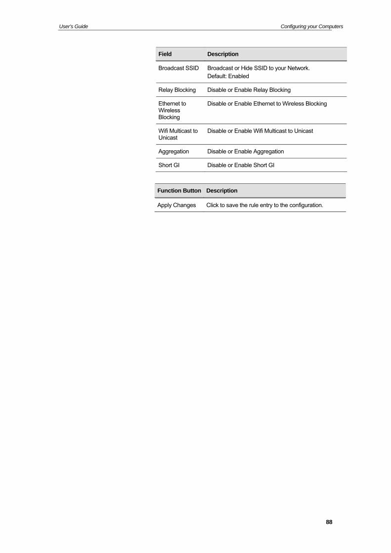
Field Description
Broadcast SSID Broadcast or Hide SSID to your Network. Default: Enabled
Relay Blocking Disable or Enable Relay Blocking
Ethernet to Wireless Blocking
Disable or Enable Ethernet to Wireless Blocking
Wifi Multicast to Unicast
Disable or Enable Wifi Multicast to Unicast
Aggregation Disable or Enable Aggregation
Short GI Disable or Enable Short GI
Function Button Description
Apply Changes Click to save the rule entry to the configuration.
88
User’s Guide Configuring your Computers
WPS
Introduction of WPS
Although home Wi-Fi networks have become more and more popular, users still have trouble with the initial set up of network. This obstacle forces users to use the open security and increases the risk of eavesdropping. Therefore, WPS is designed to ease set up of security-enabled Wi-Fi networks and subsequently network management (Wi-Fi Protected Setup Specification 1.0h.pdf, p. 8).
The largest difference between WPS-enabled devices and legacy devices is that users do not need the knowledge about SSID, channel and security settings, but they could still surf in a security-enabled Wi-Fi network. For examples, in the initial network set up, if users want to use the PIN configuration, the only thing they need to do is entering the device PIN into registrar, starting the PIN method on that device and simply wait until the device joins the network. After the PIN method is started on both sides, a registration protocol will be initiated between the registrar and the enrollee. Typically, a registrar could be an access point or other device that is capable of managing the network. An enrollee could be an access point or a station that will join the network. After the registration protocol has been done, the enrollee will receive SSID and security settings from the registrar and then join the network. In other words; if a station attempts to join a network managed by an access point with built-in internal registrar, users will need to enter station’s PIN into the web page of that access point. If the device PIN is correct and valid and users start PIN on station, the access point and the station will automatically exchange the encrypted information of the network settings under the management of AP’s internal registrar. The station then uses this information to perform authentication algorithm, join the secure network, and transmit data with the encryption algorithm. More details will be demonstrated in the following sections.
Supported WPS features
Currently, Wireless Gateway supports WPS features for AP mode, AP+WDS mode, Infrastructure-Client mode, and the wireless root interface of Universal Repeater mode.
Other modes such as WDS mode, Infrastructure-Adhoc mode, and the wireless virtual interface of Universal Repeater mode are not implemented with WPS features.
If those unsupported modes are enforced by users, WPS will be disabled. Under the configuration of every WPS-supported mode, Wireless Gateway has Push Button method and PIN method. For each method, Wireless Gateway offers different security levels included in network credential, such as open security, WEP 64 bits, WEP 128 bits, WPA2-Personal TKIP, and WPA2-Personal AES. Users could choose either one of the methods at their convenience.
89
User’s Guide Configuring your Computers
AP mode
For AP mode, Wireless Gateway supports three roles, registrar, proxy, and enrollee in registration protocol. At different scenarios, Wireless Gateway will automatically switch to an appropriate role depending on the other device’s role or a specific configuration.
AP as Enrollee
If users know AP’s PIN and enter it into external registrar, the external registrar will configure AP with a new wireless profile such as new SSID and new security settings. The external registrar does this job either utilizing the in-band EAP (wireless) or out-of-band UPnP (Ethernet). During the WPS handshake, a wireless profile is encrypted and transmitted to AP. If the handshake is successfully done, AP will be re-initialized with the new wireless profile and wait for legacy stations or WPS stations to join its network.
AP as Registrar
Wireless Gateway also has a built-in internal registrar. Whenever users enter station’s PIN into AP’s webpage, click “Start PBC”, or push the physical button, AP will switch to registrar automatically. If users apply the same method on station side and the WPS handshake is successfully done, SSID and security settings will be transmitted to that station without the risk of eavesdropping. And then the station will associate with AP in a security-enabled network.
AP as Proxy
At this state, AP is transparent to users. If users want to configure a station or any device that is capable of being an enrollee, they have to enter device’s PIN into an external registrar and choose an appropriate wireless profile. After the PIN is entered, the external registrar will inform AP this event. AP then conveys the encrypted wireless profile between the device and the external registrar. Finally, the device will use the wireless profile and associate with AP. However, the device may connect to other APs if the wireless profile does not belong to the proxy AP. Users must carefully choose the wireless profile or create a wireless profile on an external registrar.
Infrastructure-Client mode
In Infrastructure-Client mode, Wireless Gateway only supports enrollee’s role. If users click “Start PIN”, click “Start PBC”, or press the physical button on Wireless Gateway, it will start to seek WPS AP. Once users apply the same method on registrar side, Wireless Gateway will receive the wireless profile upon successfully doing the registration protocol. Then Wireless Gateway will associate with an AP.
90
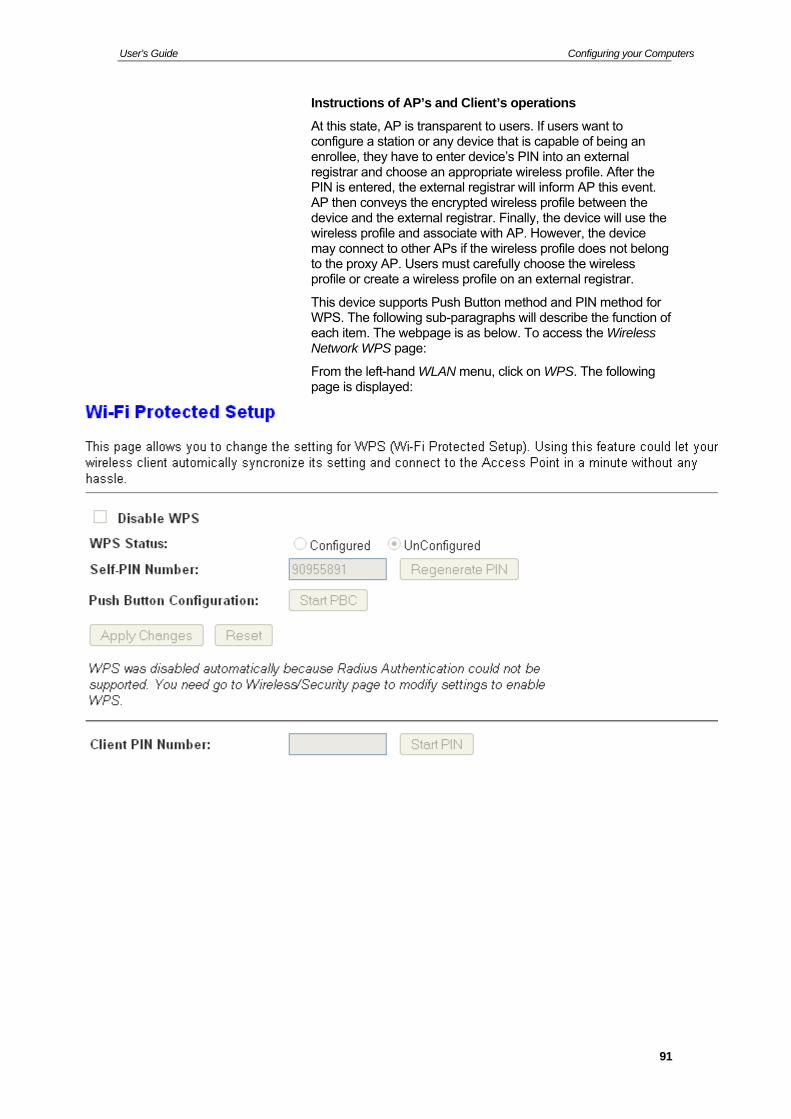
User’s Guide Configuring your Computers
Instructions of AP’s and Client’s operations
At this state, AP is transparent to users. If users want to configure a station or any device that is capable of being an enrollee, they have to enter device’s PIN into an external registrar and choose an appropriate wireless profile. After the PIN is entered, the external registrar will inform AP this event. AP then conveys the encrypted wireless profile between the device and the external registrar. Finally, the device will use the wireless profile and associate with AP. However, the device may connect to other APs if the wireless profile does not belong to the proxy AP. Users must carefully choose the wireless profile or create a wireless profile on an external registrar.
This device supports Push Button method and PIN method for WPS. The following sub-paragraphs will describe the function of each item. The webpage is as below. To access the Wireless Network WPS page:
From the left-hand WLAN menu, click on WPS. The following page is displayed:
91
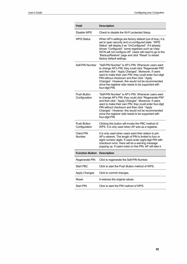
User’s Guide Configuring your Computers
Field Description
Disable WPS Check to disable the Wi-Fi protected Setup.
WPS Status When AP’s settings are factory default (out of box), it is set to open security and un-configured state. “WPS Status” will display it as “UnConfigured”. If it already shows “Configured”, some registrars such as Vista WCN will not configure AP. Users will need to go to the “Backup/Restore” page and click “Reset” to reload factory default settings.
Self-PIN Number “Self-PIN Number” is AP’s PIN. Whenever users want to change AP’s PIN, they could click “Regenerate PIN” and then click “ Apply Changes”. Moreover, if users want to make their own PIN, they could enter four-digit PIN without checksum and then click “ Apply Changes”. However, this would not be recommended since the registrar side needs to be supported with four-digit PIN.
Push Button Configuration
“Self-PIN Number” is AP’s PIN. Whenever users want to change AP’s PIN, they could click “Regenerate PIN” and then click “ Apply Changes”. Moreover, if users want to make their own PIN, they could enter four-digit PIN without checksum and then click “ Apply Changes”. However, this would not be recommended since the registrar side needs to be supported with four-digit PIN.
Push Button Configuration
Clicking this button will invoke the PBC method of WPS. It is only used when AP acts as a registrar.
Client PIN Number
It is only used when users want their station to join AP’s network. The length of PIN is limited to four or eight numeric digits. If users enter eight-digit PIN with checksum error, there will be a warning message popping up. If users insist on this PIN, AP will take it.
Function Button Description
Regenerate PIN Click to regenerate the Self-PIN Number.
Start PBC Click to start the Push Button method of WPS.
Apply Changes Click to commit changes.
Reset It restores the original values.
Start PIN Click to start the PIN method of WPS.
92
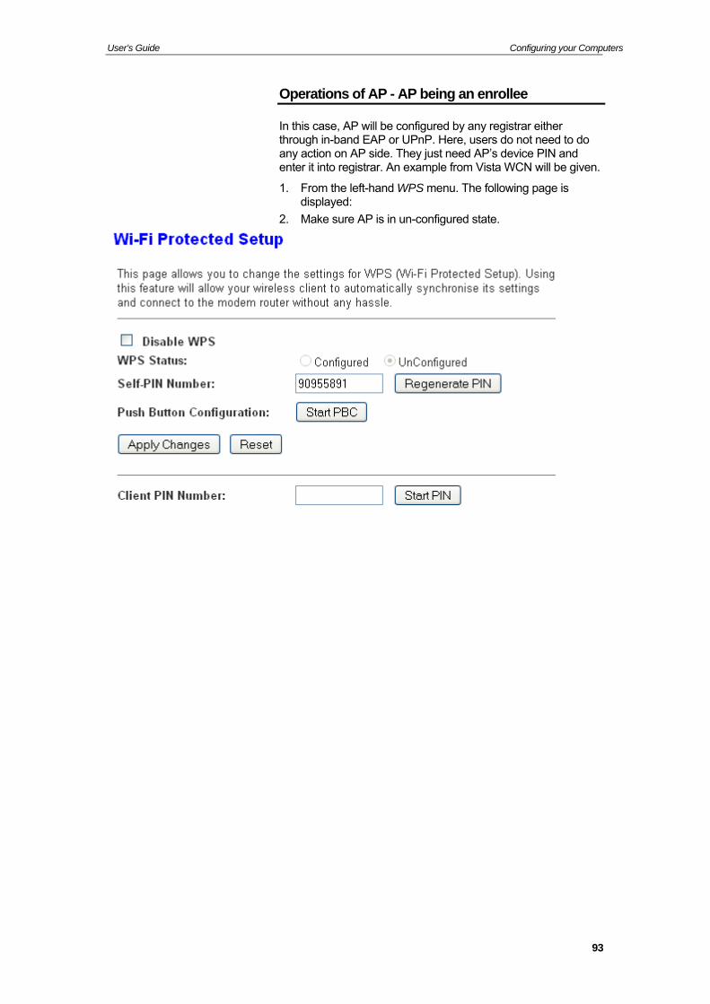
User’s Guide Configuring your Computers
Operations of AP - AP being an enrollee
In this case, AP will be configured by any registrar either through in-band EAP or UPnP. Here, users do not need to do any action on AP side. They just need AP’s device PIN and enter it into registrar. An example from Vista WCN will be given.
1. From the left-hand WPS menu. The following page is displayed:
2. Make sure AP is in un-configured state.
93
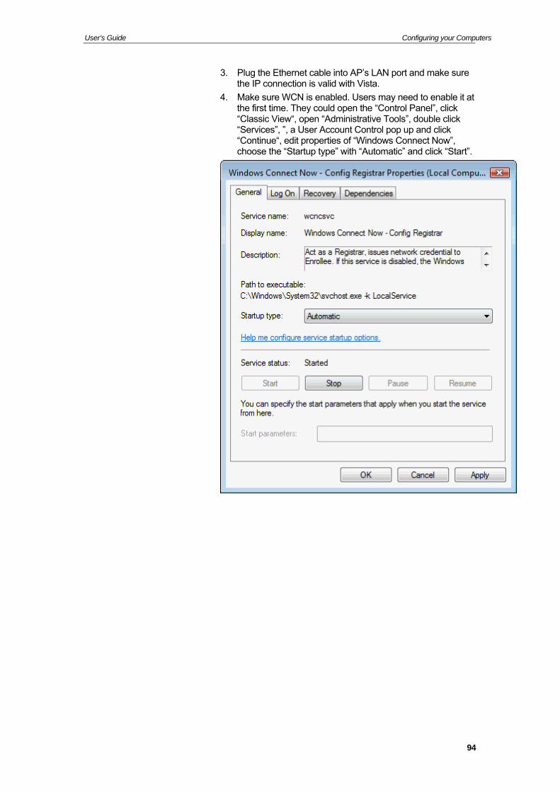
User’s Guide Configuring your Computers
3. Plug the Ethernet cable into AP’s LAN port and make sure the IP connection is valid with Vista.
4. Make sure WCN is enabled. Users may need to enable it at the first time. They could open the “Control Panel”, click “Classic View“, open “Administrative Tools”, double click “Services”, ”, a User Account Control pop up and click “Continue“, edit properties of “Windows Connect Now”, choose the “Startup type” with “Automatic” and click “Start”.
94
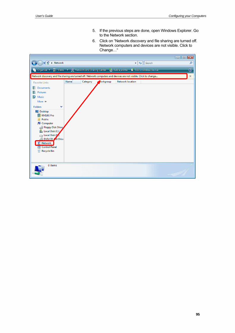
User’s Guide Configuring your Computers
5. If the previous steps are done, open Windows Explorer. Go to the Network section.
6. Click on “Network discovery and file sharing are turned off. Network computers and devices are not visible. Click to Change…“
95
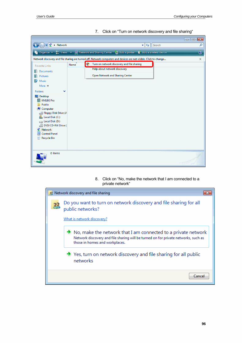
User’s Guide Configuring your Computers
7. Click on “Turn on network discovery and file sharing“
8. Click on “No, make the network that I am connected to a private network“
96
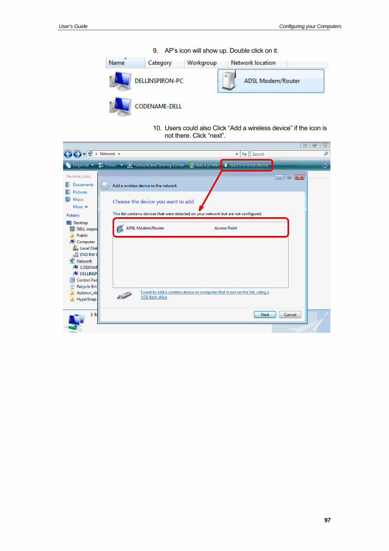
User’s Guide Configuring your Computers
9. AP’s icon will show up. Double click on it.
10. Users could also Click “Add a wireless device” if the icon is not there. Click “next”.
97

User’s Guide Configuring your Computers
11. Enter AP’s Self-PIN Number and click “next”.
98
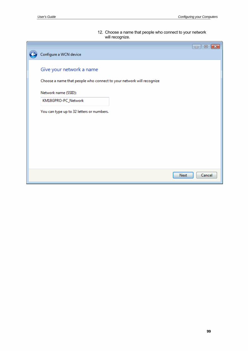
User’s Guide Configuring your Computers
12. Choose a name that people who connect to your network will recognize.
99
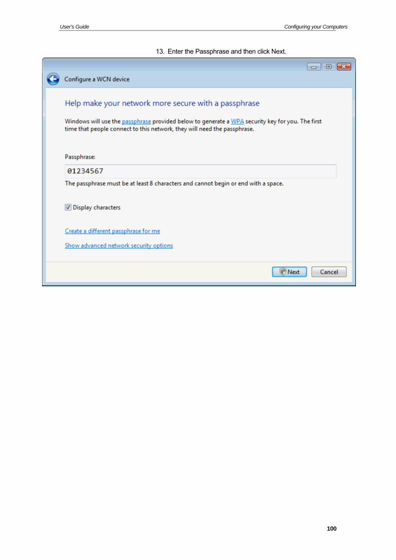
User’s Guide Configuring your Computers
13. Enter the Passphrase and then click Next.
100
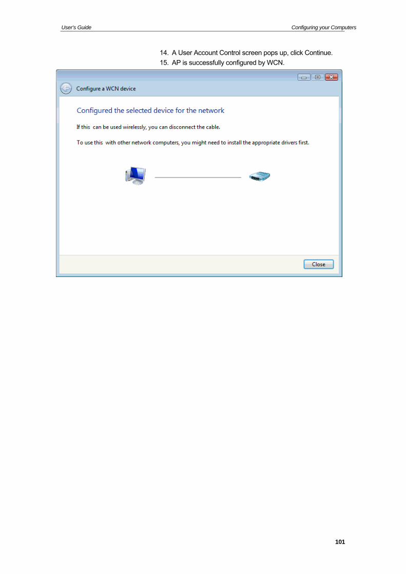
User’s Guide Configuring your Computers
14. A User Account Control screen pops up, click Continue.
15. AP is successfully configured by WCN.
101
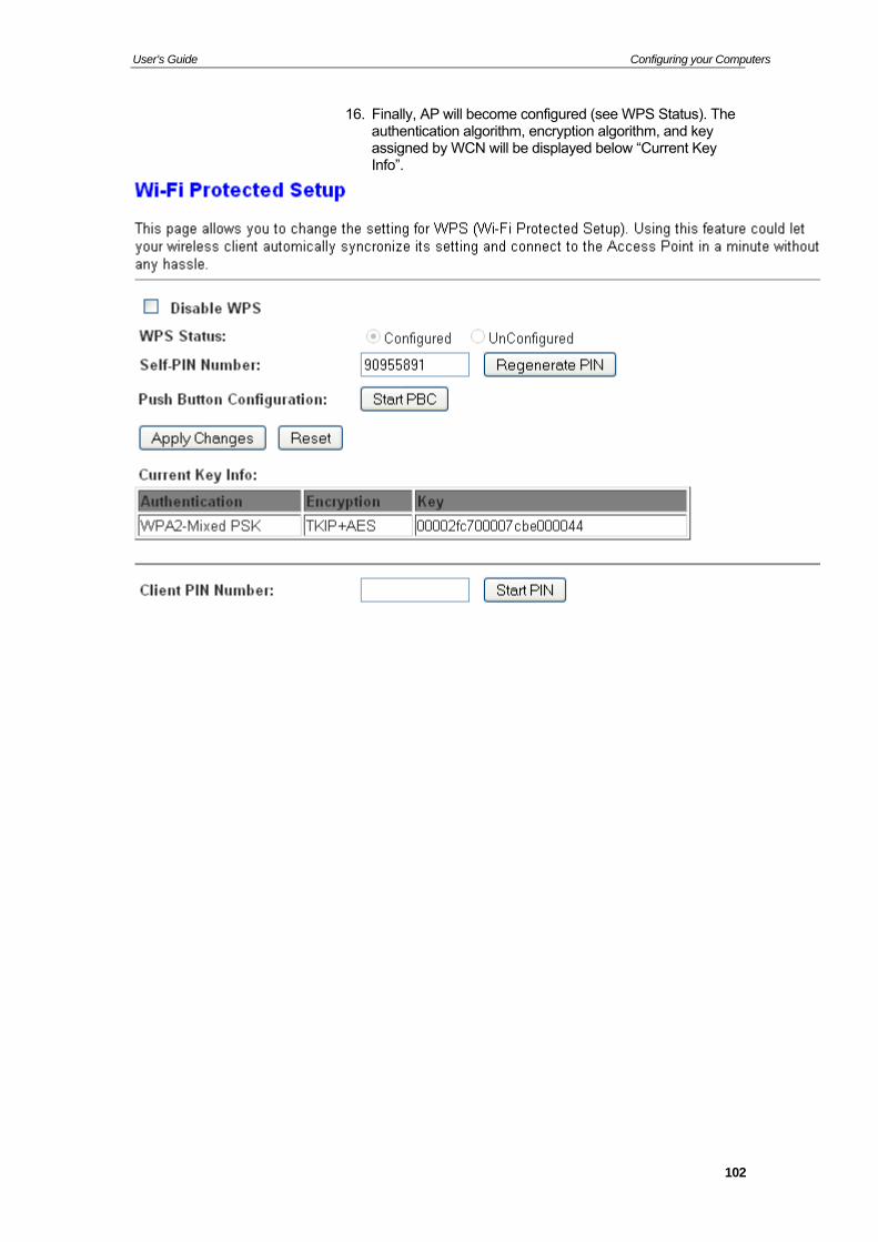
User’s Guide Configuring your Computers
16. Finally, AP will become configured (see WPS Status). The authentication algorithm, encryption algorithm, and key assigned by WCN will be displayed below “Current Key Info”.
102
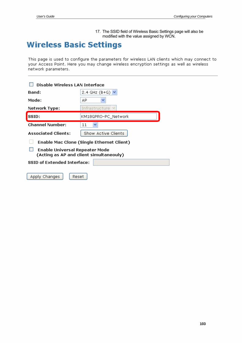
User’s Guide Configuring your Computers
17. The SSID field of Wireless Basic Settings page will also be modified with the value assigned by WCN.
103
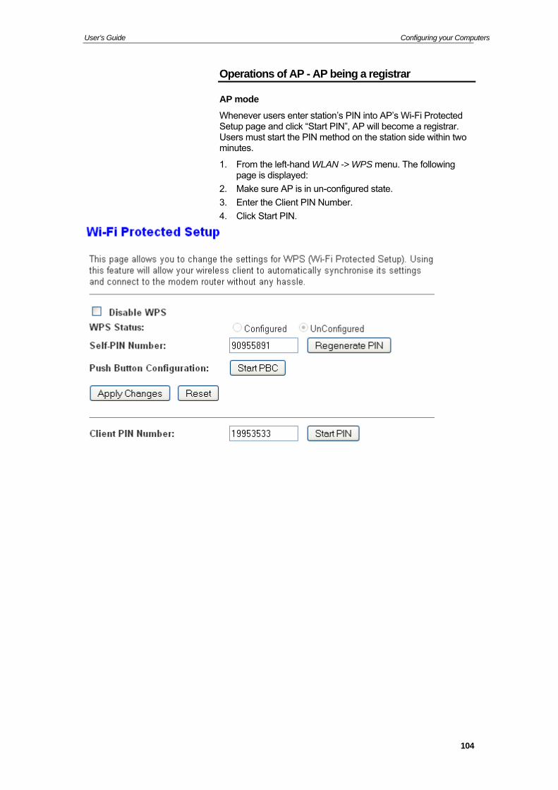
User’s Guide Configuring your Computers
Operations of AP - AP being a registrar
AP mode
Whenever users enter station’s PIN into AP’s Wi-Fi Protected Setup page and click “Start PIN”, AP will become a registrar. Users must start the PIN method on the station side within two minutes.
1. From the left-hand WLAN -> WPS menu. The following page is displayed:
2. Make sure AP is in un-configured state.
3. Enter the Client PIN Number.
4. Click Start PIN.
104
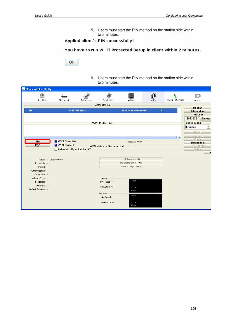
User’s Guide Configuring your Computers
5. Users must start the PIN method on the station side within two minutes.
6. Users must start the PIN method on the station side within two minutes.
105
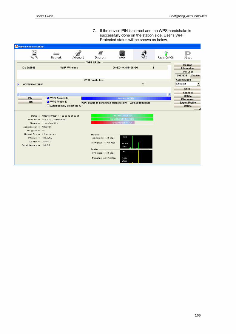
User’s Guide Configuring your Computers
7. If the device PIN is correct and the WPS handshake is successfully done on the station side, User’s Wi-Fi Protected status will be shown as below.
106
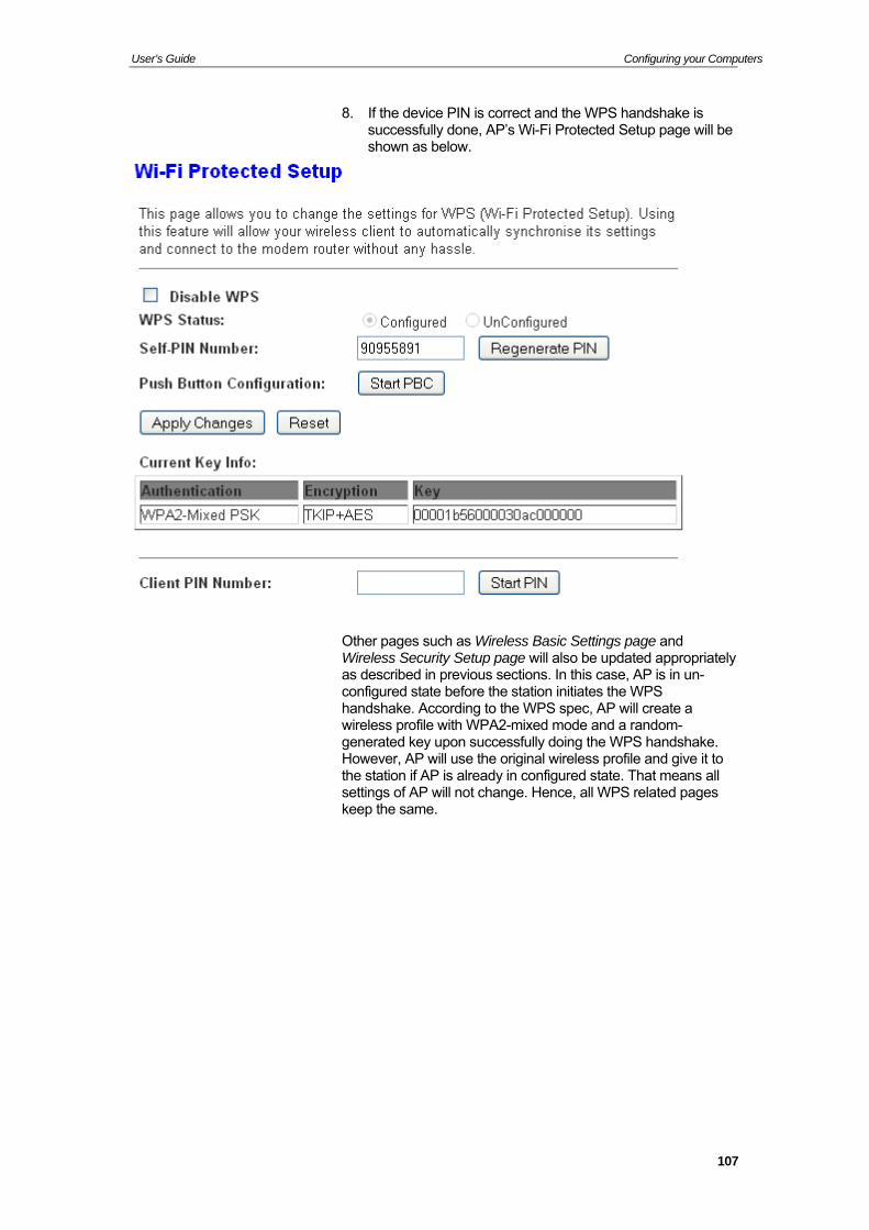
User’s Guide Configuring your Computers
8. If the device PIN is correct and the WPS handshake is successfully done, AP’s Wi-Fi Protected Setup page will be shown as below.
Other pages such as Wireless Basic Settings page and Wireless Security Setup page will also be updated appropriately as described in previous sections. In this case, AP is in un-configured state before the station initiates the WPS handshake. According to the WPS spec, AP will create a wireless profile with WPA2-mixed mode and a random-generated key upon successfully doing the WPS handshake. However, AP will use the original wireless profile and give it to the station if AP is already in configured state. That means all settings of AP will not change. Hence, all WPS related pages keep the same.
107
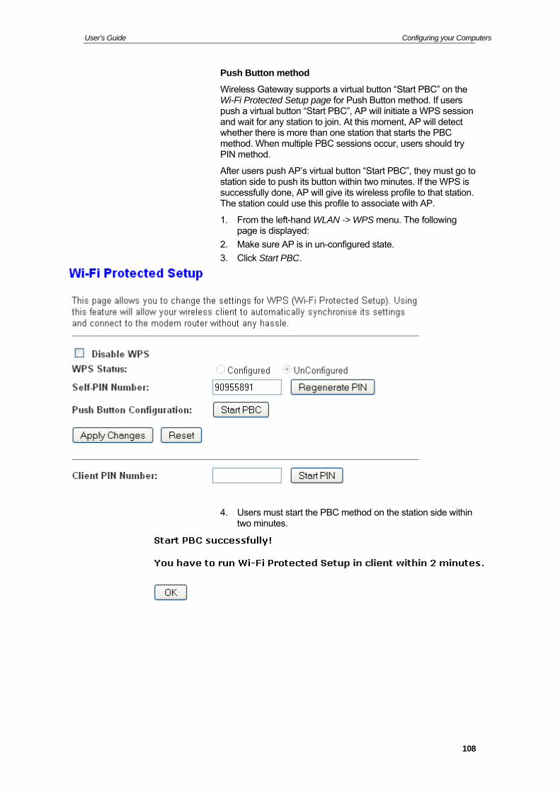
User’s Guide Configuring your Computers
Push Button method
Wireless Gateway supports a virtual button “Start PBC” on the Wi-Fi Protected Setup page for Push Button method. If users push a virtual button “Start PBC”, AP will initiate a WPS session and wait for any station to join. At this moment, AP will detect whether there is more than one station that starts the PBC method. When multiple PBC sessions occur, users should try PIN method.
After users push AP’s virtual button “Start PBC”, they must go to station side to push its button within two minutes. If the WPS is successfully done, AP will give its wireless profile to that station. The station could use this profile to associate with AP.
1. From the left-hand WLAN -> WPS menu. The following page is displayed:
2. Make sure AP is in un-configured state.
3. Click Start PBC.
4. Users must start the PBC method on the station side within two minutes.
108
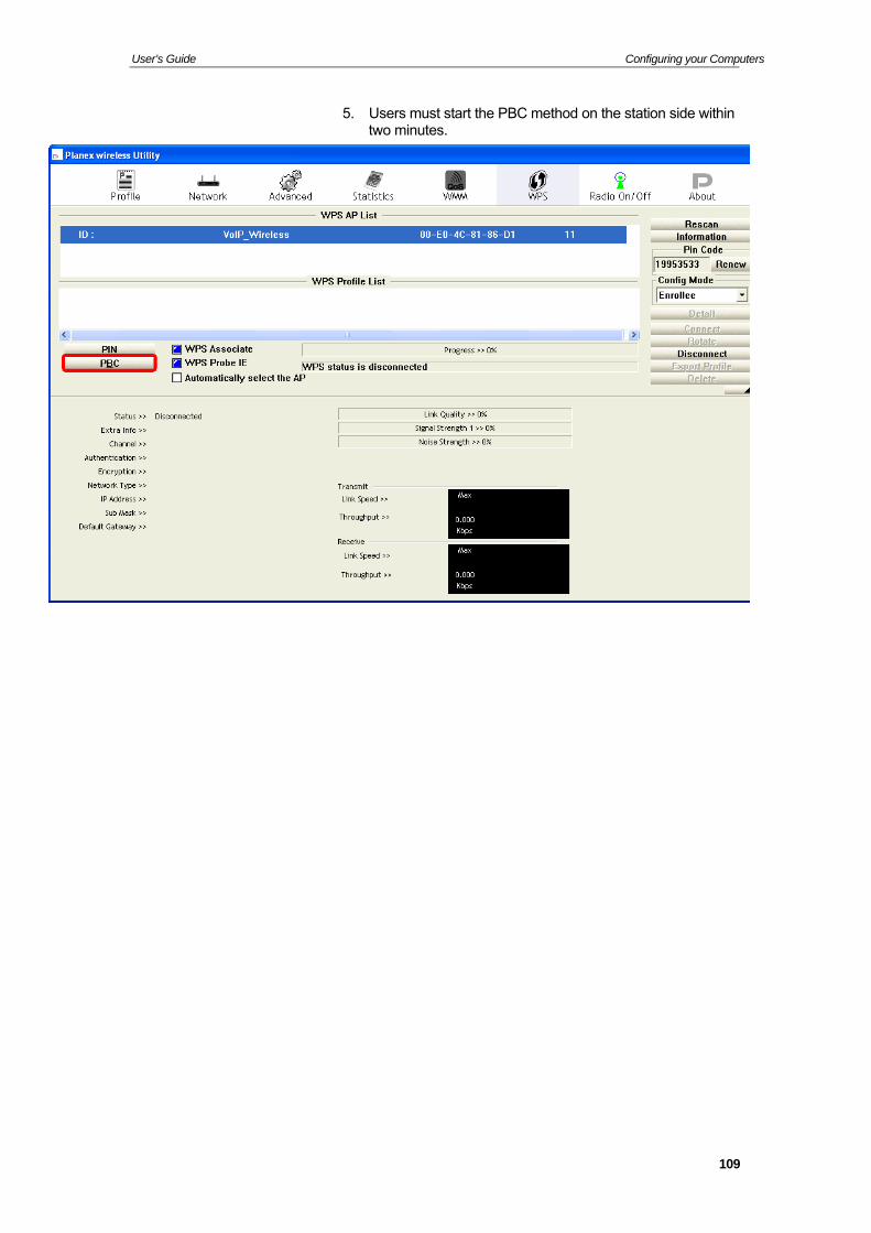
User’s Guide Configuring your Computers
5. Users must start the PBC method on the station side within two minutes.
109
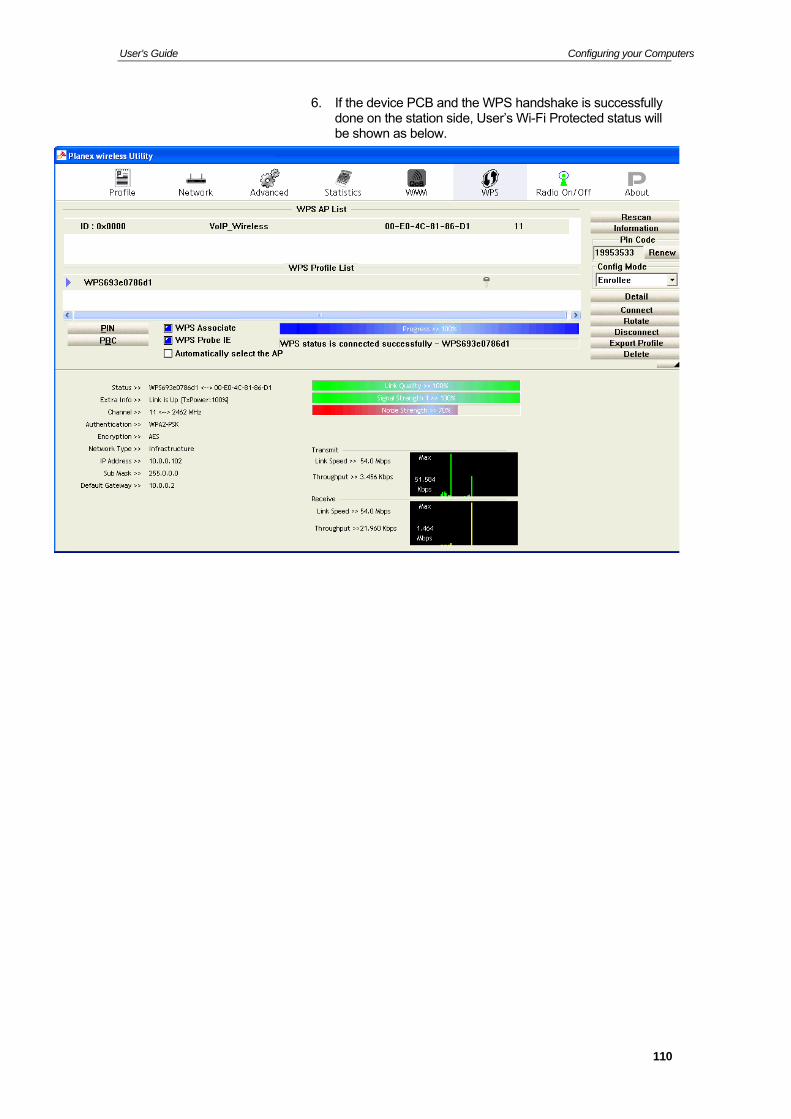
User’s Guide Configuring your Computers
6. If the device PCB and the WPS handshake is successfully done on the station side, User’s Wi-Fi Protected status will be shown as below.
110
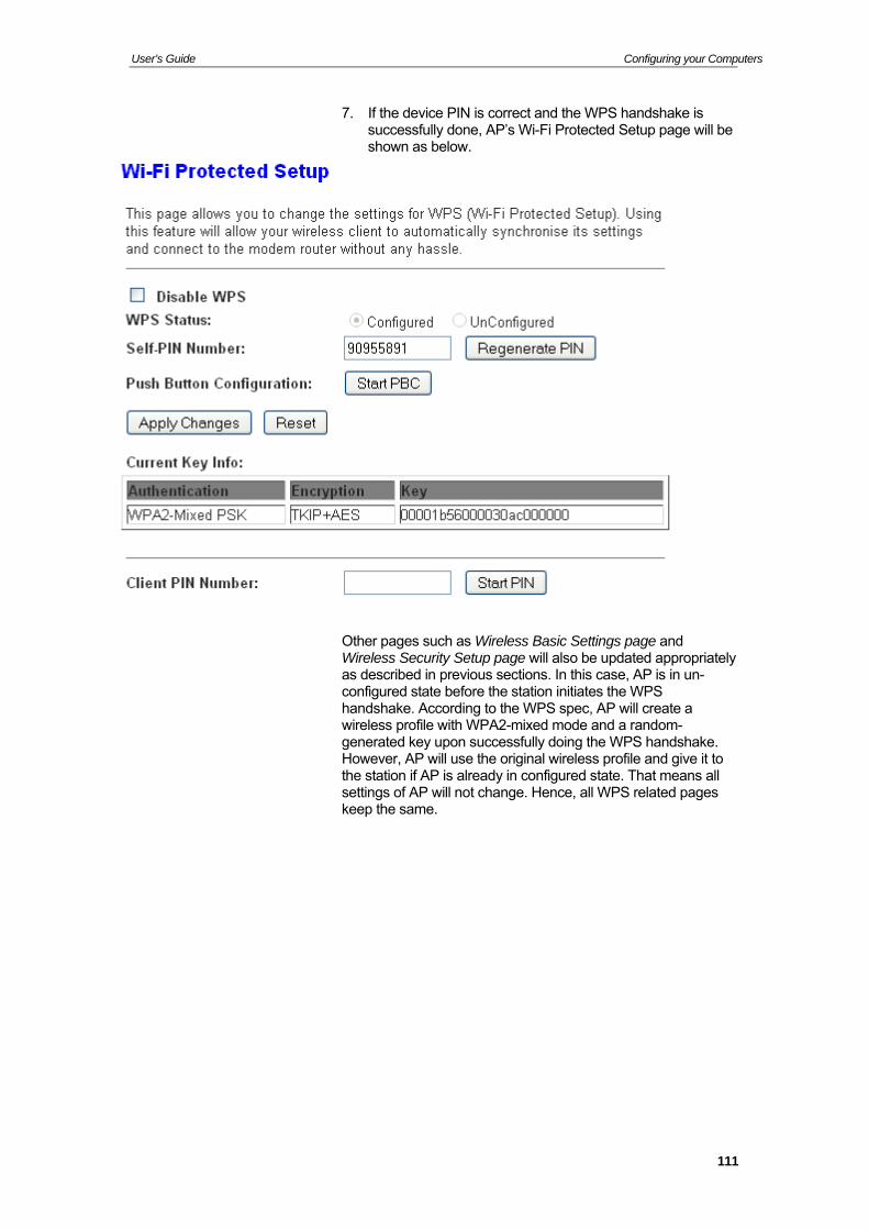
User’s Guide Configuring your Computers
7. If the device PIN is correct and the WPS handshake is successfully done, AP’s Wi-Fi Protected Setup page will be shown as below.
Other pages such as Wireless Basic Settings page and Wireless Security Setup page will also be updated appropriately as described in previous sections. In this case, AP is in un-configured state before the station initiates the WPS handshake. According to the WPS spec, AP will create a wireless profile with WPA2-mixed mode and a random-generated key upon successfully doing the WPS handshake. However, AP will use the original wireless profile and give it to the station if AP is already in configured state. That means all settings of AP will not change. Hence, all WPS related pages keep the same.
111
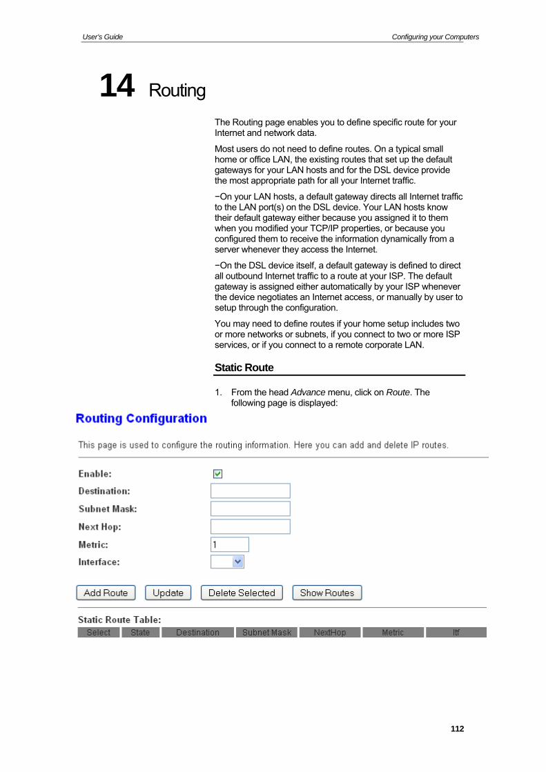
User’s Guide Configuring your Computers
14 Routing
The Routing page enables you to define specific route for your Internet and network data.
Most users do not need to define routes. On a typical small home or office LAN, the existing routes that set up the default gateways for your LAN hosts and for the DSL device provide the most appropriate path for all your Internet traffic.
−On your LAN hosts, a default gateway directs all Internet traffic to the LAN port(s) on the DSL device. Your LAN hosts know their default gateway either because you assigned it to them when you modified your TCP/IP properties, or because you configured them to receive the information dynamically from a server whenever they access the Internet.
−On the DSL device itself, a default gateway is defined to direct all outbound Internet traffic to a route at your ISP. The default gateway is assigned either automatically by your ISP whenever the device negotiates an Internet access, or manually by user to setup through the configuration.
You may need to define routes if your home setup includes two or more networks or subnets, if you connect to two or more ISP services, or if you connect to a remote corporate LAN.
Static Route
1. From the head Advance menu, click on Route. The following page is displayed:
112
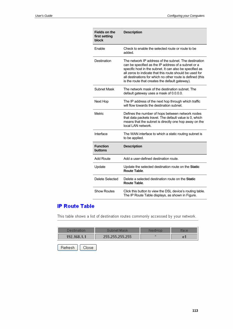
User’s Guide Configuring your Computers
Fields on the first setting block
Description
Enable Check to enable the selected route or route to be added.
Destination The network IP address of the subnet. The destination can be specified as the IP address of a subnet or a specific host in the subnet. It can also be specified as all zeros to indicate that this route should be used for all destinations for which no other route is defined (this is the route that creates the default gateway).
Subnet Mask The network mask of the destination subnet. The default gateway uses a mask of 0.0.0.0.
Next Hop The IP address of the next hop through which traffic will flow towards the destination subnet.
Metric Defines the number of hops between network nodes that data packets travel. The default value is 0, which means that the subnet is directly one hop away on the local LAN network.
Interface The WAN interface to which a static routing subnet is to be applied.
Function buttons
Description
Add Route Add a user-defined destination route.
Update Update the selected destination route on the Static Route Table.
Delete Selected Delete a selected destination route on the Static Route Table.
Show Routes Click this button to view the DSL device’s routing table. The IP Route Table displays, as shown in Figure.
113
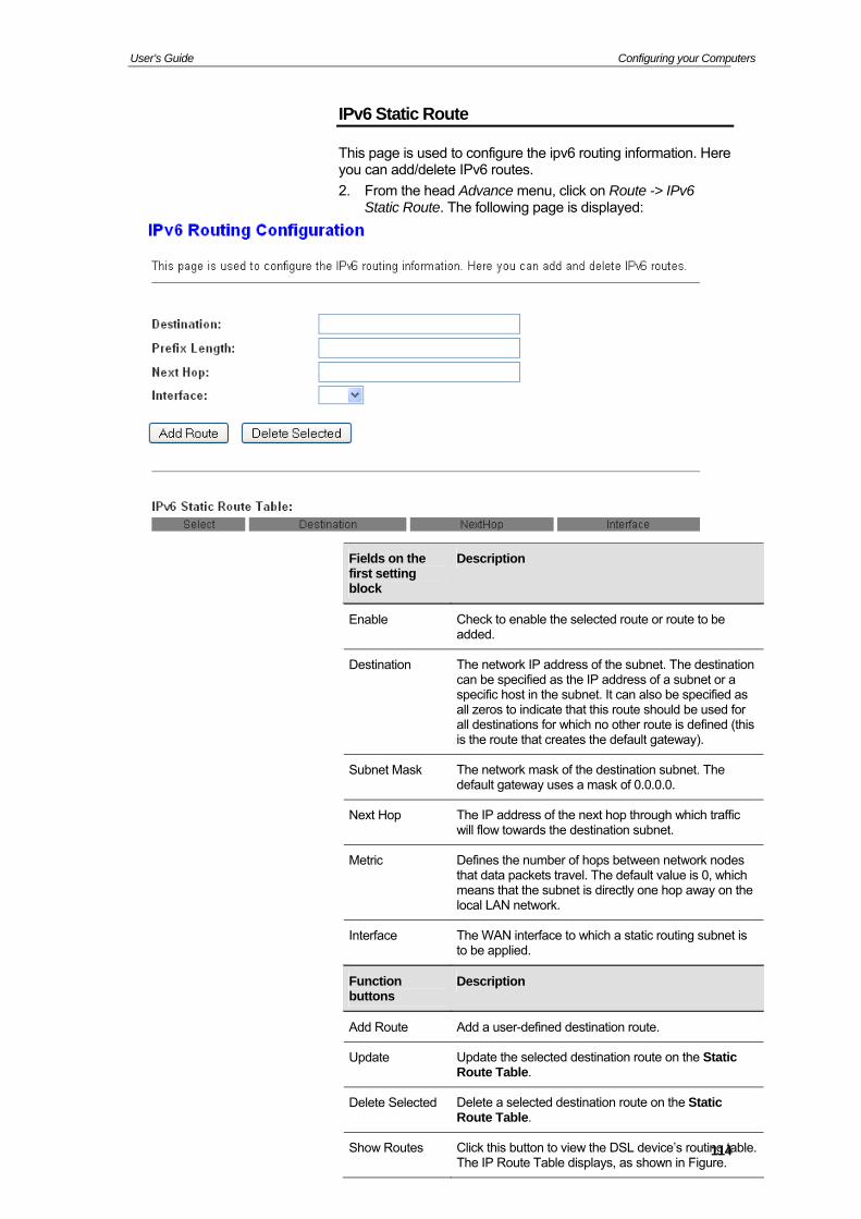
User’s Guide Configuring your Computers
IPv6 Static Route
This page is used to configure the ipv6 routing information. Here you can add/delete IPv6 routes.
2. From the head Advance menu, click on Route -> IPv6 Static Route. The following page is displayed:
114
Fields on the first setting block
Description
Enable Check to enable the selected route or route to be added.
Destination The network IP address of the subnet. The destination can be specified as the IP address of a subnet or a specific host in the subnet. It can also be specified as all zeros to indicate that this route should be used for all destinations for which no other route is defined (this is the route that creates the default gateway).
Subnet Mask The network mask of the destination subnet. The default gateway uses a mask of 0.0.0.0.
Next Hop The IP address of the next hop through which traffic will flow towards the destination subnet.
Metric Defines the number of hops between network nodes that data packets travel. The default value is 0, which means that the subnet is directly one hop away on the local LAN network.
Interface The WAN interface to which a static routing subnet is to be applied.
Function buttons
Description
Add Route Add a user-defined destination route.
Update Update the selected destination route on the Static Route Table.
Delete Selected Delete a selected destination route on the Static Route Table.
Show Routes Click this button to view the DSL device’s routing table. The IP Route Table displays, as shown in Figure.
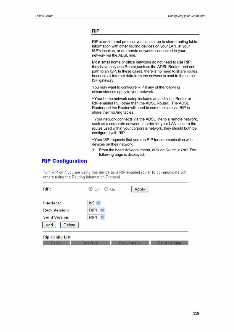
User’s Guide Configuring your Computers
RIP
RIP is an Internet protocol you can set up to share routing table information with other routing devices on your LAN, at your ISP’s location, or on remote networks connected to your network via the ADSL line.
Most small home or office networks do not need to use RIP; they have only one Router,such as the ADSL Router, and one path to an ISP. In these cases, there is no need to share routes, because all Internet data from the network is sent to the same ISP gateway.
You may want to configure RIP if any of the following circumstances apply to your network:
−Your home network setup includes an additional Router or RIP-enabled PC (other than the ADSL Router). The ADSL Router and the Router will need to communicate via RIP to share their routing tables.
−Your network connects via the ADSL line to a remote network, such as a corporate network. In order for your LAN to learn the routes used within your corporate network, they should both be configured with RIP.
−Your ISP requests that you run RIP for communication with devices on their network.
1. From the head Advance menu, click on Route -> RIP. The following page is displayed:
115
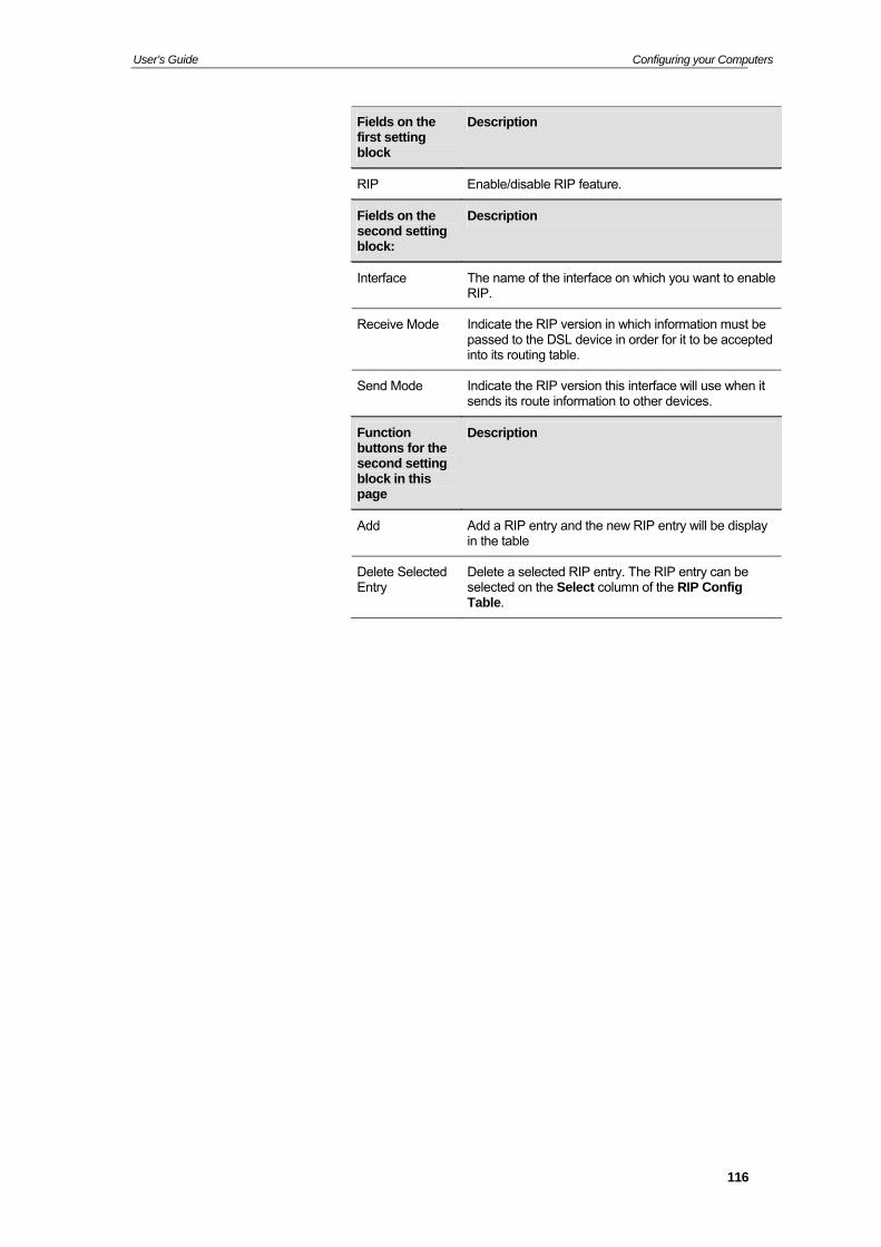
User’s Guide Configuring your Computers
Fields on the first setting block
Description
RIP Enable/disable RIP feature.
Fields on the second setting block:
Description
Interface The name of the interface on which you want to enable RIP.
Receive Mode Indicate the RIP version in which information must be passed to the DSL device in order for it to be accepted into its routing table.
Send Mode Indicate the RIP version this interface will use when it sends its route information to other devices.
Function buttons for the second setting block in this page
Description
Add Add a RIP entry and the new RIP entry will be display in the table
Delete Selected Entry
Delete a selected RIP entry. The RIP entry can be selected on the Select column of the RIP Config Table.
116
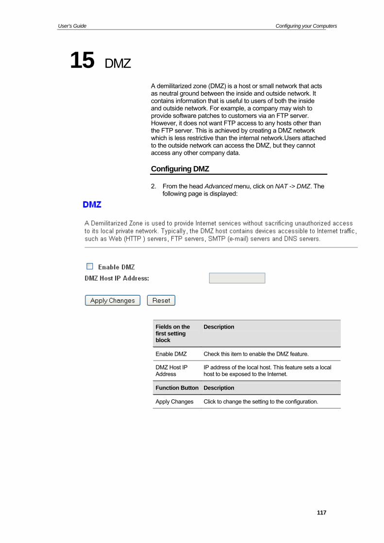
User’s Guide Configuring your Computers
15 DMZ
A demilitarized zone (DMZ) is a host or small network that acts as neutral ground between the inside and outside network. It contains information that is useful to users of both the inside and outside network. For example, a company may wish to provide software patches to customers via an FTP server. However, it does not want FTP access to any hosts other than the FTP server. This is achieved by creating a DMZ network which is less restrictive than the internal network.Users attached to the outside network can access the DMZ, but they cannot access any other company data.
Configuring DMZ
2. From the head Advanced menu, click on NAT -> DMZ. The following page is displayed:
Fields on the first setting block
Description
Enable DMZ Check this item to enable the DMZ feature.
DMZ Host IP Address
IP address of the local host. This feature sets a local host to be exposed to the Internet.
Function Button Description
Apply Changes Click to change the setting to the configuration.
117
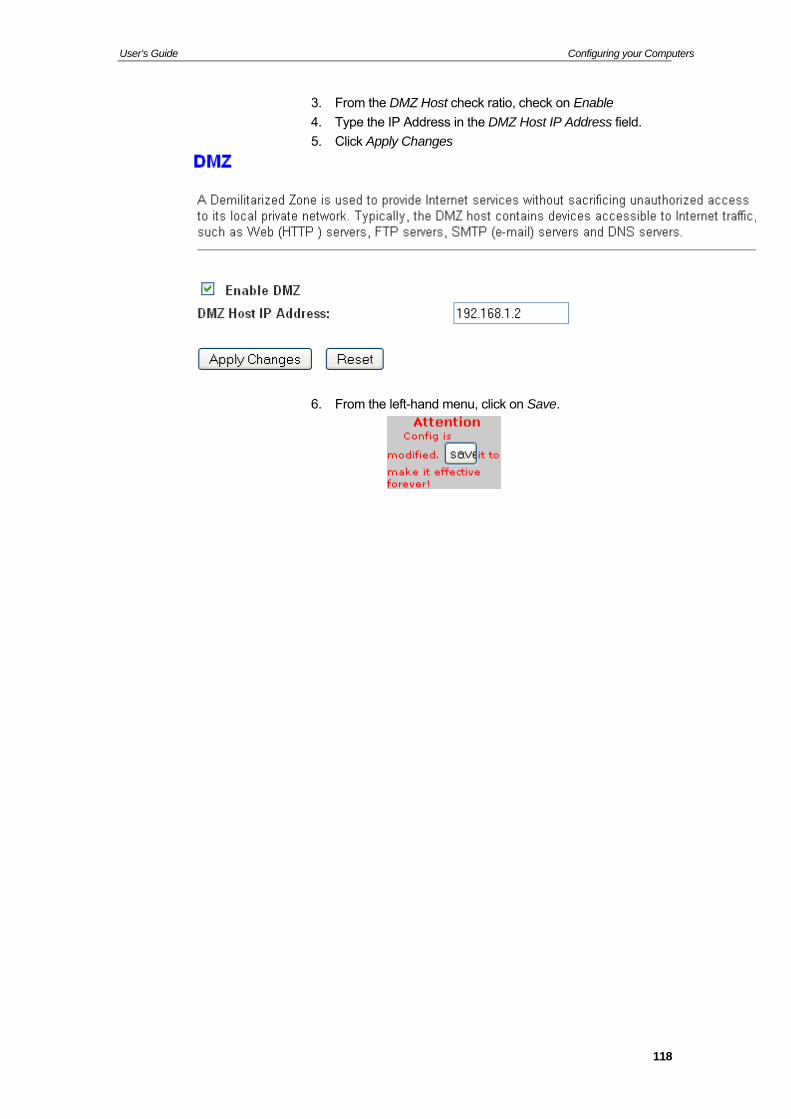
User’s Guide Configuring your Computers
3. From the DMZ Host check ratio, check on Enable
4. Type the IP Address in the DMZ Host IP Address field.
5. Click Apply Changes
6. From the left-hand menu, click on Save.
118
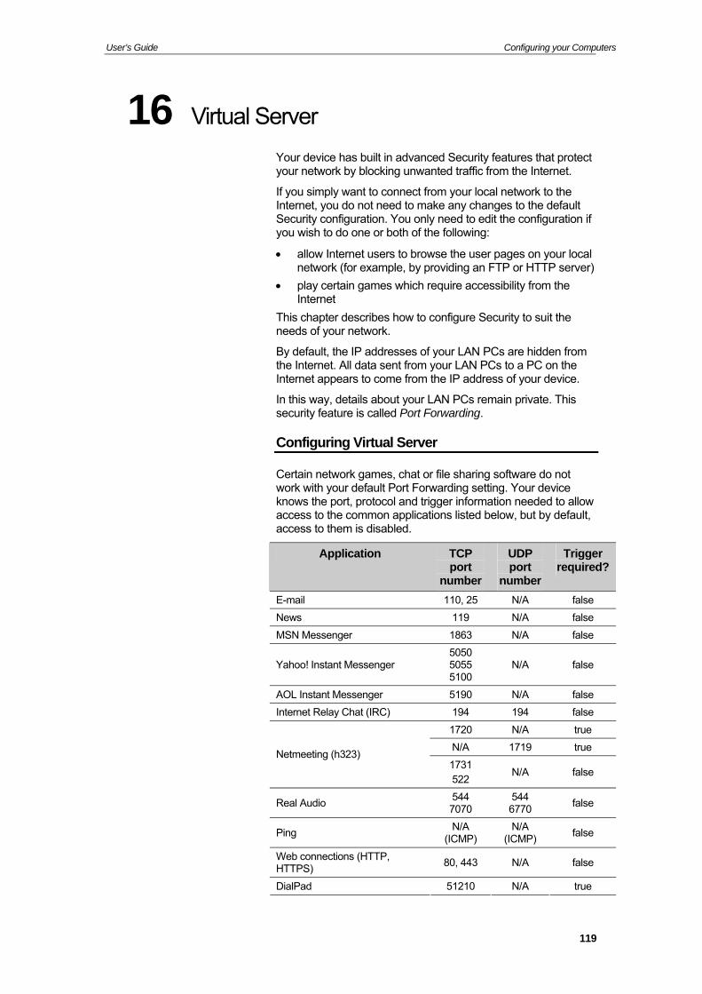
User’s Guide Configuring your Computers
16 Virtual Server
Your device has built in advanced Security features that protect your network by blocking unwanted traffic from the Internet.
If you simply want to connect from your local network to the Internet, you do not need to make any changes to the default Security configuration. You only need to edit the configuration if you wish to do one or both of the following:
allow Internet users to browse the user pages on your local network (for example, by providing an FTP or HTTP server)
play certain games which require accessibility from the Internet
This chapter describes how to configure Security to suit the needs of your network.
By default, the IP addresses of your LAN PCs are hidden from the Internet. All data sent from your LAN PCs to a PC on the Internet appears to come from the IP address of your device.
In this way, details about your LAN PCs remain private. This security feature is called Port Forwarding.
Configuring Virtual Server
Certain network games, chat or file sharing software do not work with your default Port Forwarding setting. Your device knows the port, protocol and trigger information needed to allow access to the common applications listed below, but by default, access to them is disabled.
Application TCP port
number
UDP port
number
Trigger required?
E-mail 110, 25 N/A false
News 119 N/A false
MSN Messenger 1863 N/A false
Yahoo! Instant Messenger 5050 5055 5100
N/A false
AOL Instant Messenger 5190 N/A false
Internet Relay Chat (IRC) 194 194 false
1720 N/A true
N/A 1719 true Netmeeting (h323)
1731 522
N/A false
Real Audio 544 7070
544 6770
false
Ping N/A
(ICMP) N/A
(ICMP) false
Web connections (HTTP, HTTPS)
80, 443 N/A false
DialPad 51210 N/A true
119
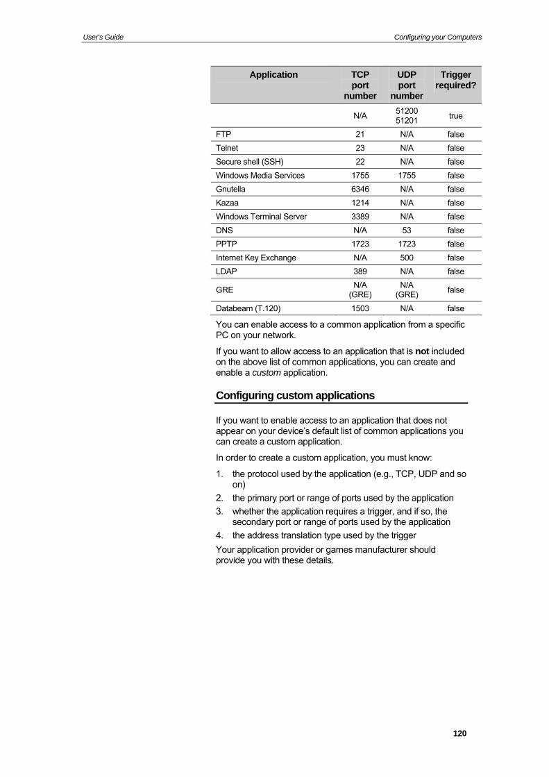
User’s Guide Configuring your Computers
Application TCP UDP Trigger port
number port required?
number
N/A 51200 51201
true
FTP 21 N/A false
Telnet 23 N/A false
Secure shell (SSH) 22 N/A false
Windows Media Services 1755 1755 false
Gnutella 6346 N/A false
Kazaa 1214 N/A false
Windows Terminal Server 3389 N/A false
DNS N/A 53 false
PPTP 1723 1723 false
Internet Key Exchange N/A 500 false
LDAP 389 N/A false
GRE N/A
(GRE) N/A
(GRE) false
Databeam (T.120) 1503 N/A false
You can enable access to a common application from a specific PC on your network.
If you want to allow access to an application that is not included on the above list of common applications, you can create and enable a custom application.
Configuring custom applications
If you want to enable access to an application that does not appear on your device’s default list of common applications you can create a custom application.
In order to create a custom application, you must know:
1. the protocol used by the application (e.g., TCP, UDP and so on)
2. the primary port or range of ports used by the application
3. whether the application requires a trigger, and if so, the secondary port or range of ports used by the application
4. the address translation type used by the trigger
Your application provider or games manufacturer should provide you with these details.
120
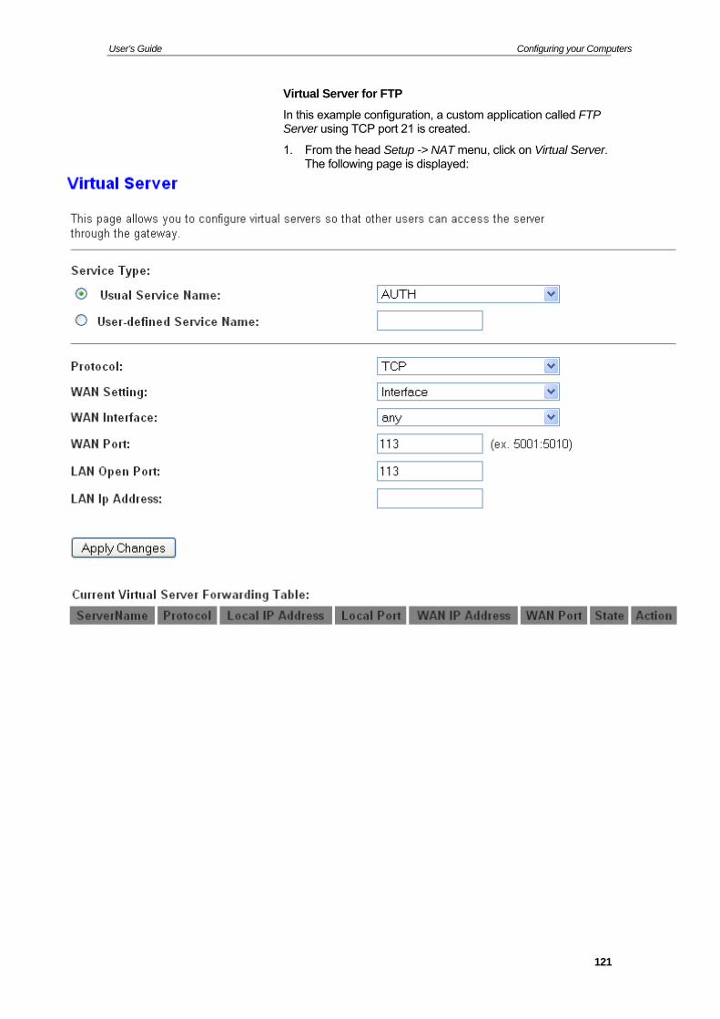
User’s Guide Configuring your Computers
Virtual Server for FTP
In this example configuration, a custom application called FTP Server using TCP port 21 is created.
1. From the head Setup -> NAT menu, click on Virtual Server. The following page is displayed:
121
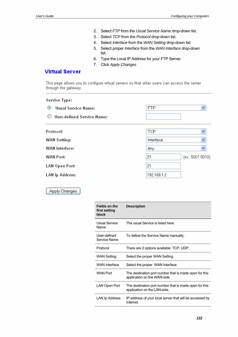
User’s Guide Configuring your Computers
2. Select FTP from the Usual Service Name drop-down list.
3. Select TCP from the Protocol drop-down list.
4. Select Interface from the WAN Setting drop-down list.
5. Select proper Interface from the WAN Interface drop-down list.
6. Type the Local IP Address for your FTP Server.
7. Click Apply Changes
Fields on the first setting block
Description
Usual Service Name
The usual Service is listed here.
User-defined Service Name
To define the Service Name manually.
Protocol There are 2 options available: TCP, UDP.
WAN Setting Select the proper WAN Setting
WAN Interface Select the proper WAN Interface
WAN Port The destination port number that is made open for this application on the WAN-side
LAN Open Port The destination port number that is made open for this application on the LAN-side.
LAN Ip Address IP address of your local server that will be accessed by Internet.
122
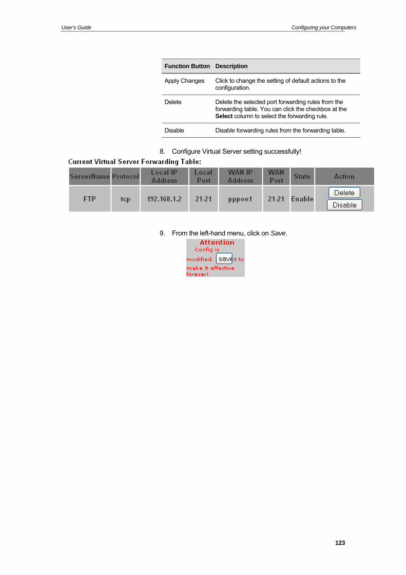
User’s Guide Configuring your Computers
Function Button Description
Apply Changes Click to change the setting of default actions to the configuration.
Delete Delete the selected port forwarding rules from the forwarding table. You can click the checkbox at the Select column to select the forwarding rule.
Disable Disable forwarding rules from the forwarding table.
8. Configure Virtual Server setting successfully!
9. From the left-hand menu, click on Save.
123
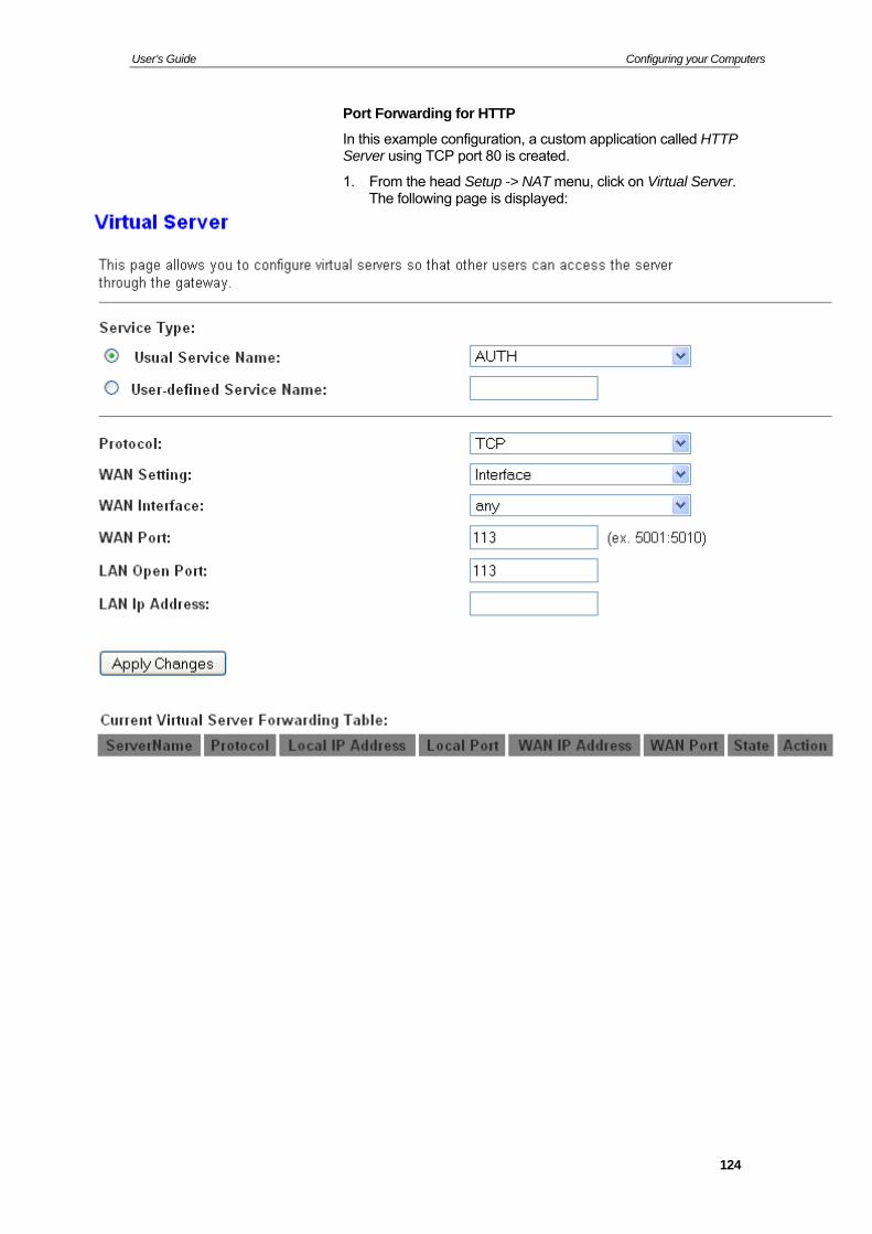
User’s Guide Configuring your Computers
Port Forwarding for HTTP
In this example configuration, a custom application called HTTP Server using TCP port 80 is created.
1. From the head Setup -> NAT menu, click on Virtual Server. The following page is displayed:
124
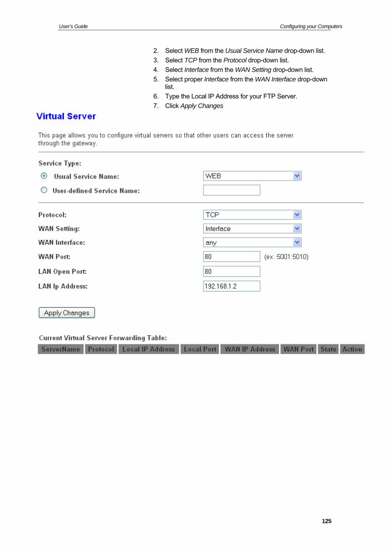
User’s Guide Configuring your Computers
2. Select WEB from the Usual Service Name drop-down list.
3. Select TCP from the Protocol drop-down list.
4. Select Interface from the WAN Setting drop-down list.
5. Select proper Interface from the WAN Interface drop-down list.
6. Type the Local IP Address for your FTP Server.
7. Click Apply Changes
125
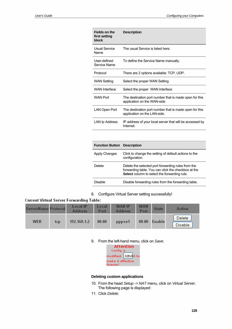
User’s Guide Configuring your Computers
Fields on the first setting block
Description
Usual Service Name
The usual Service is listed here.
User-defined Service Name
To define the Service Name manually.
Protocol There are 2 options available: TCP, UDP.
WAN Setting Select the proper WAN Setting
WAN Interface Select the proper WAN Interface
WAN Port The destination port number that is made open for this application on the WAN-side
LAN Open Port The destination port number that is made open for this application on the LAN-side.
LAN Ip Address IP address of your local server that will be accessed by Internet.
Function Button Description
Apply Changes Click to change the setting of default actions to the configuration.
Delete Delete the selected port forwarding rules from the forwarding table. You can click the checkbox at the Select column to select the forwarding rule.
Disable Disable forwarding rules from the forwarding table.
8. Configure Virtual Server setting successfully!
9. From the left-hand menu, click on Save.
Deleting custom applications
10. From the head Setup -> NAT menu, click on Virtual Server. The following page is displayed:
11. Click Delete.
126
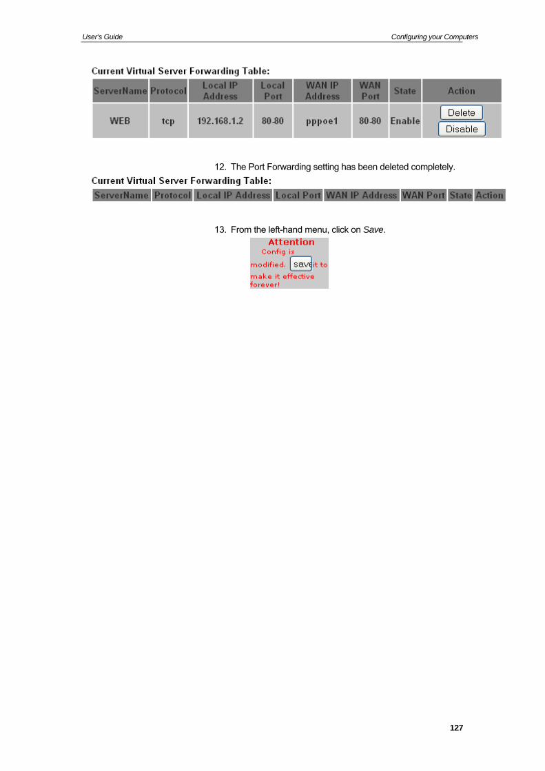
User’s Guide Configuring your Computers
12. The Port Forwarding setting has been deleted completely.
13. From the left-hand menu, click on Save.
127
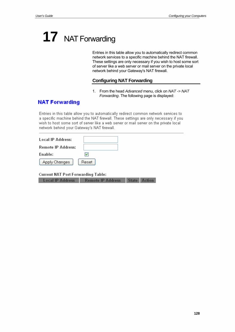
User’s Guide Configuring your Computers
17 NAT Forwarding
Entries in this table allow you to automatically redirect common network services to a specific machine behind the NAT firewall. These settings are only necessary if you wish to host some sort of server like a web server or mail server on the private local network behind your Gateway's NAT firewall.
Configuring NAT Forwarding
1. From the head Advanced menu, click on NAT -> NAT Forwarding. The following page is displayed:
128

User’s Guide Configuring your Computers
18 ALG
To setup NAT ALG and Pass-Through configuration
Configuring ALG
2. From the head Advanced menu, click on NAT -> ALG. The following page is displayed:
129
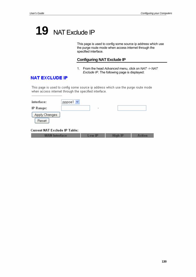
User’s Guide Configuring your Computers
19 NAT Exclude IP
This page is used to config some source ip address which use the purge route mode when access internet through the specified interface.
Configuring NAT Exclude IP
1. From the head Advanced menu, click on NAT -> NAT Exclude IP. The following page is displayed:
130
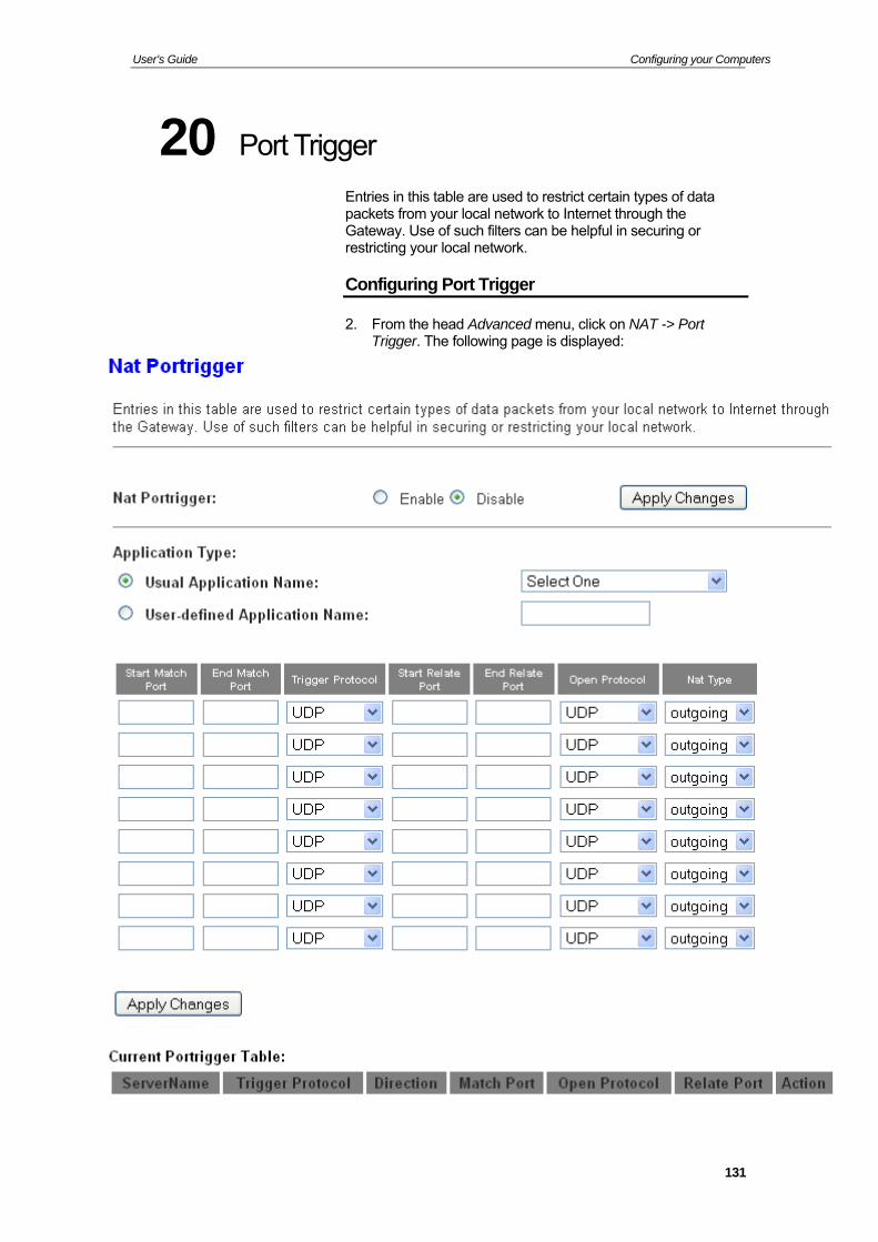
User’s Guide Configuring your Computers
20 Port Trigger
Entries in this table are used to restrict certain types of data packets from your local network to Internet through the Gateway. Use of such filters can be helpful in securing or restricting your local network.
Configuring Port Trigger
2. From the head Advanced menu, click on NAT -> Port Trigger. The following page is displayed:
131
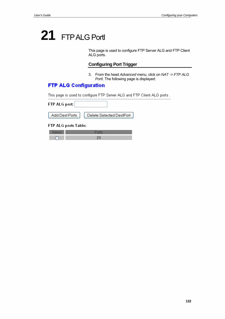
User’s Guide Configuring your Computers
21 FTP ALG Portl
This page is used to configure FTP Server ALG and FTP Client ALG ports.
Configuring Port Trigger
3. From the head Advanced menu, click on NAT -> FTP ALG Portl. The following page is displayed:
132
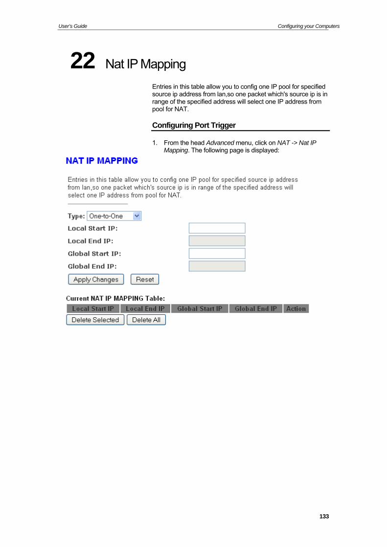
User’s Guide Configuring your Computers
22 Nat IP Mapping
Entries in this table allow you to config one IP pool for specified source ip address from lan,so one packet which's source ip is in range of the specified address will select one IP address from pool for NAT.
Configuring Port Trigger
1. From the head Advanced menu, click on NAT -> Nat IP Mapping. The following page is displayed:
133
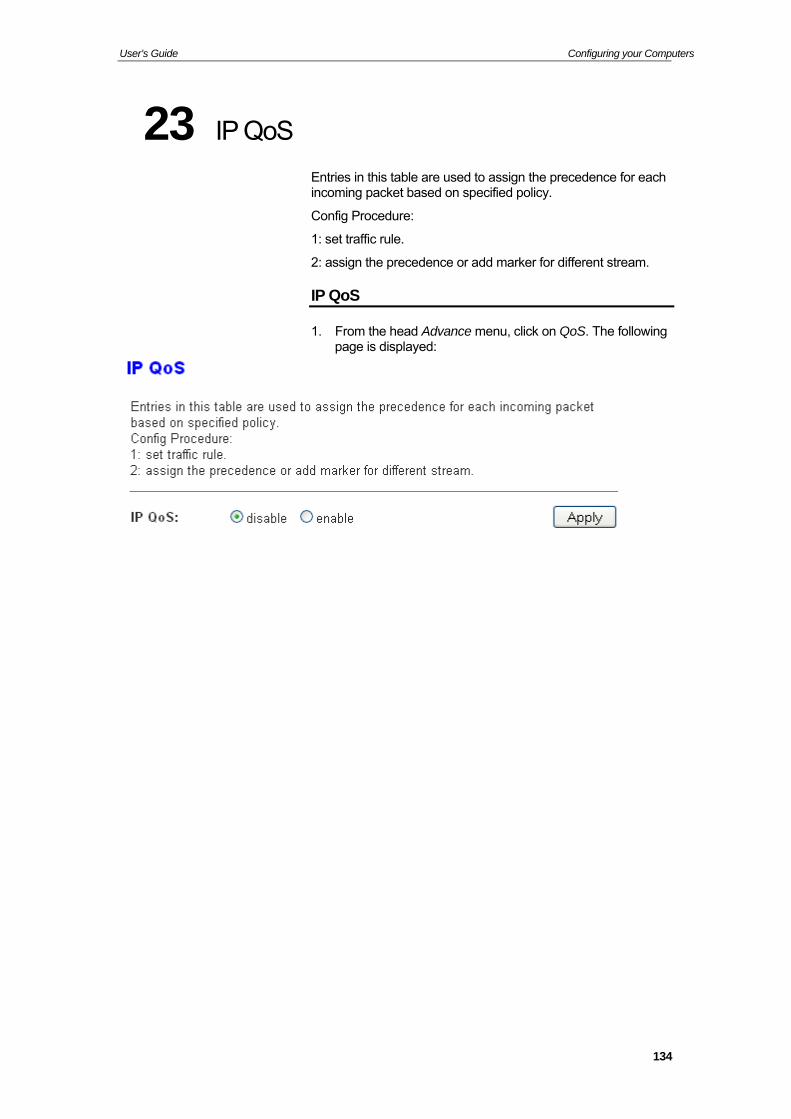
User’s Guide Configuring your Computers
23 IP QoS
Entries in this table are used to assign the precedence for each incoming packet based on specified policy.
Config Procedure:
1: set traffic rule.
2: assign the precedence or add marker for different stream.
IP QoS
1. From the head Advance menu, click on QoS. The following page is displayed:
134
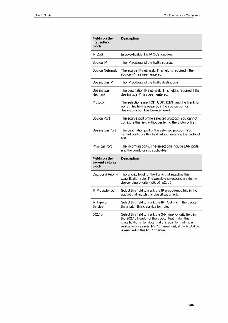
User’s Guide Configuring your Computers
Fields on the first setting block
Description
IP QoS Enable/disable the IP QoS function.
Source IP The IP address of the traffic source.
Source Netmask The source IP netmask. This field is required if the source IP has been entered.
Destination IP The IP address of the traffic destination.
Destination Netmask
The destination IP netmask. This field is required if the destination IP has been entered.
Protocol The selections are TCP, UDP, ICMP and the blank for none. This field is required if the source port or destination port has been entered.
Source Port The source port of the selected protocol. You cannot configure this field without entering the protocol first.
Destination Port The destination port of the selected protocol. You cannot configure this field without entering the protocol first.
Physical Port The incoming ports. The selections include LAN ports, and the blank for not applicable.
Fields on the second setting block
Description
Outbound Priority The priority level for the traffic that matches this classification rule. The possible selections are (in the descending priority): p0, p1, p2, p3.
IP Precedence Select this field to mark the IP precedence bits in the packet that match this classification rule.
IP Type of Service
Select this field to mark the IP TOS bits in the packet that match this classification rule.
802.1p Select this field to mark the 3-bit user-priority field in the 802.1p header of the packet that match this classification rule. Note that this 802.1p marking is workable on a given PVC channel only if the VLAN tag is enabled in this PVC channel.
135
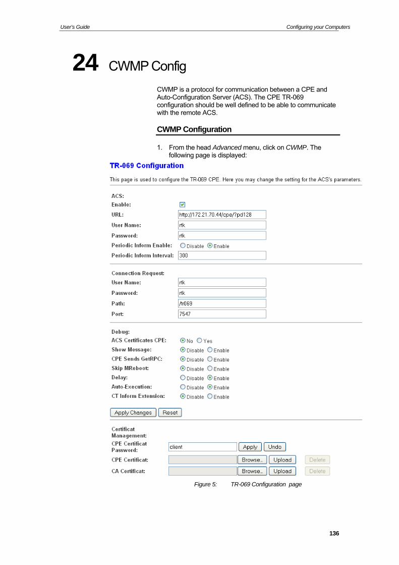
User’s Guide Configuring your Computers
24 CWMP Config
CWMP is a protocol for communication between a CPE and Auto-Configuration Server (ACS). The CPE TR-069 configuration should be well defined to be able to communicate with the remote ACS.
CWMP Configuration
1. From the head Advanced menu, click on CWMP. The following page is displayed:
Figure 5: TR-069 Configuration page
136
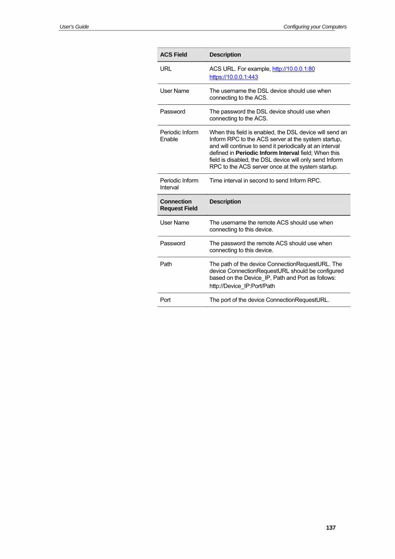
User’s Guide Configuring your Computers
ACS Field Description
URL ACS URL. For example, http://10.0.0.1:80 https://10.0.0.1:443
User Name The username the DSL device should use when connecting to the ACS.
Password The password the DSL device should use when connecting to the ACS.
Periodic Inform Enable
When this field is enabled, the DSL device will send an Inform RPC to the ACS server at the system startup, and will continue to send it periodically at an interval defined in Periodic Inform Interval field; When this field is disabled, the DSL device will only send Inform RPC to the ACS server once at the system startup.
Periodic Inform Interval
Time interval in second to send Inform RPC.
Connection Request Field
Description
User Name The username the remote ACS should use when connecting to this device.
Password The password the remote ACS should use when connecting to this device.
Path The path of the device ConnectionRequestURL. The device ConnectionRequestURL should be configured based on the Device_IP, Path and Port as follows: http://Device_IP:Port/Path
Port The port of the device ConnectionRequestURL.
137
User’s Guide Configuring your Computers
25 Port Mapping
The DSL device provides multiple interface groups. Up to five interface groups are supported including one default group. The LAN and WAN interfaces could be included. Traffic coming from one interface of a group can only be flowed to the interfaces in the same interface group. Thus, the DSL device can isolate traffic from group to group for some application. By default, all the interfaces (LAN and WAN) belong to the default group, and the other four groups are all empty. It is possible to assign any interface to any group but only one group.
Port Mapping
1. From the head Advance menu, click on Port Mapping. The following page is displayed:
138
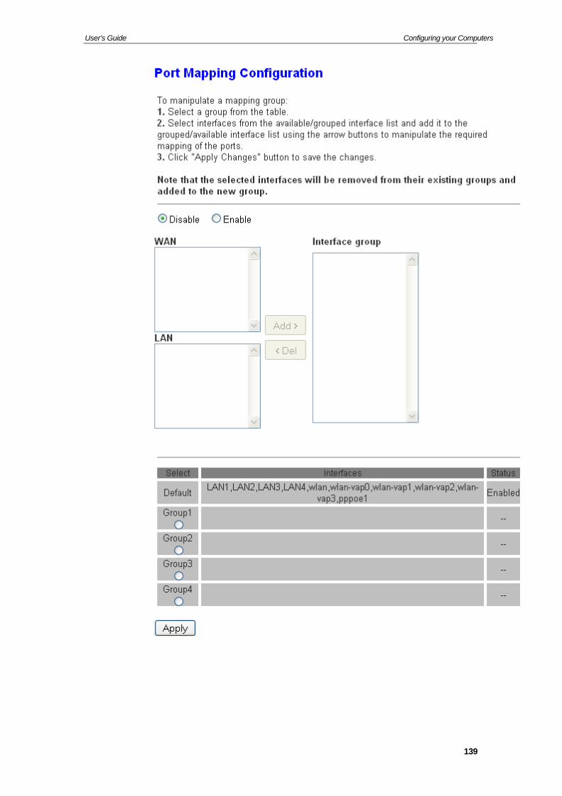
User’s Guide Configuring your Computers
139
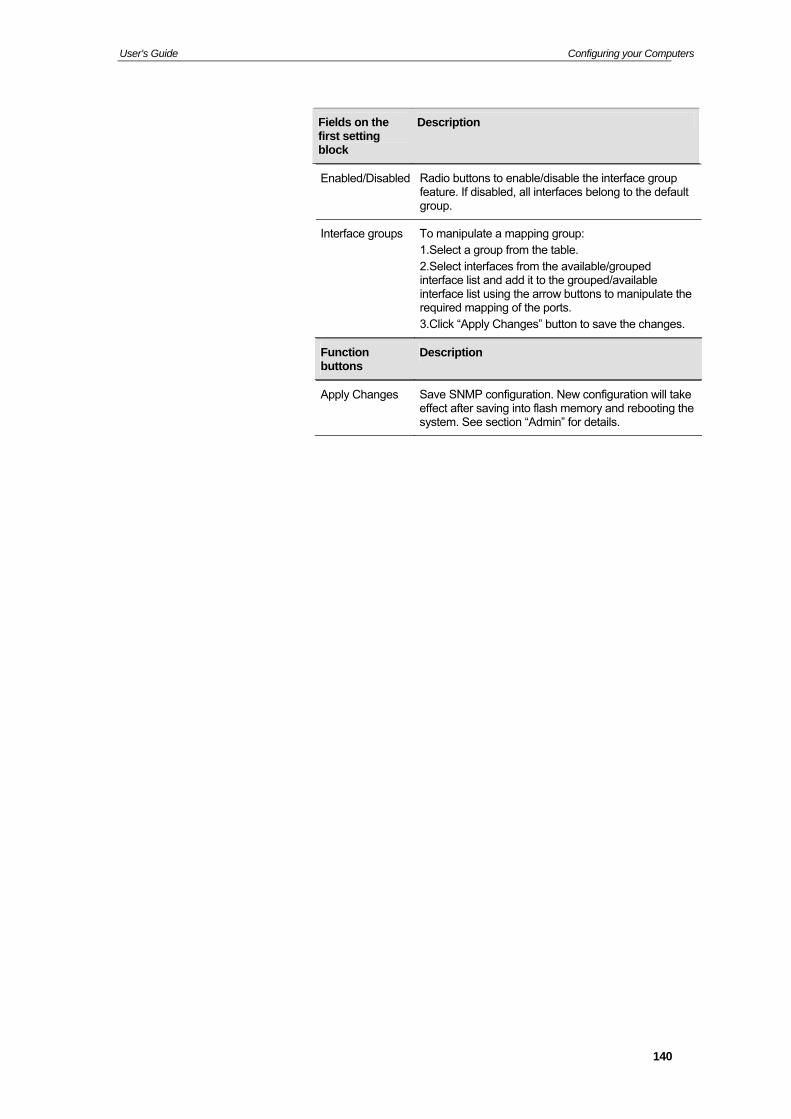
User’s Guide Configuring your Computers
Fields on the first setting block
Description
Enabled/Disabled Radio buttons to enable/disable the interface group feature. If disabled, all interfaces belong to the default group.
Interface groups To manipulate a mapping group: 1.Select a group from the table. 2.Select interfaces from the available/grouped interface list and add it to the grouped/available interface list using the arrow buttons to manipulate the required mapping of the ports. 3.Click “Apply Changes” button to save the changes.
Function buttons
Description
Apply Changes Save SNMP configuration. New configuration will take effect after saving into flash memory and rebooting the system. See section “Admin” for details.
140
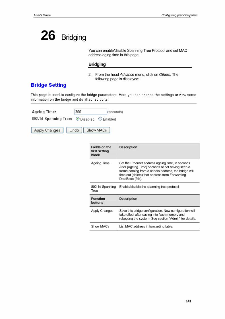
User’s Guide Configuring your Computers
26 Bridging
You can enable/disable Spanning Tree Protocol and set MAC address aging time in this page.
Bridging
2. From the head Advance menu, click on Others. The following page is displayed:
Fields on the first setting block
Description
Ageing Time Set the Ethernet address ageing time, in seconds. After [Ageing Time] seconds of not having seen a frame coming from a certain address, the bridge will time out (delete) that address from Forwarding DataBase (fdb).
802.1d Spanning Tree
Enable/disable the spanning tree protocol
Function buttons
Description
Apply Changes Save this bridge configuration. New configuration will take effect after saving into flash memory and rebooting the system. See section “Admin” for details.
Show MACs List MAC address in forwarding table.
141
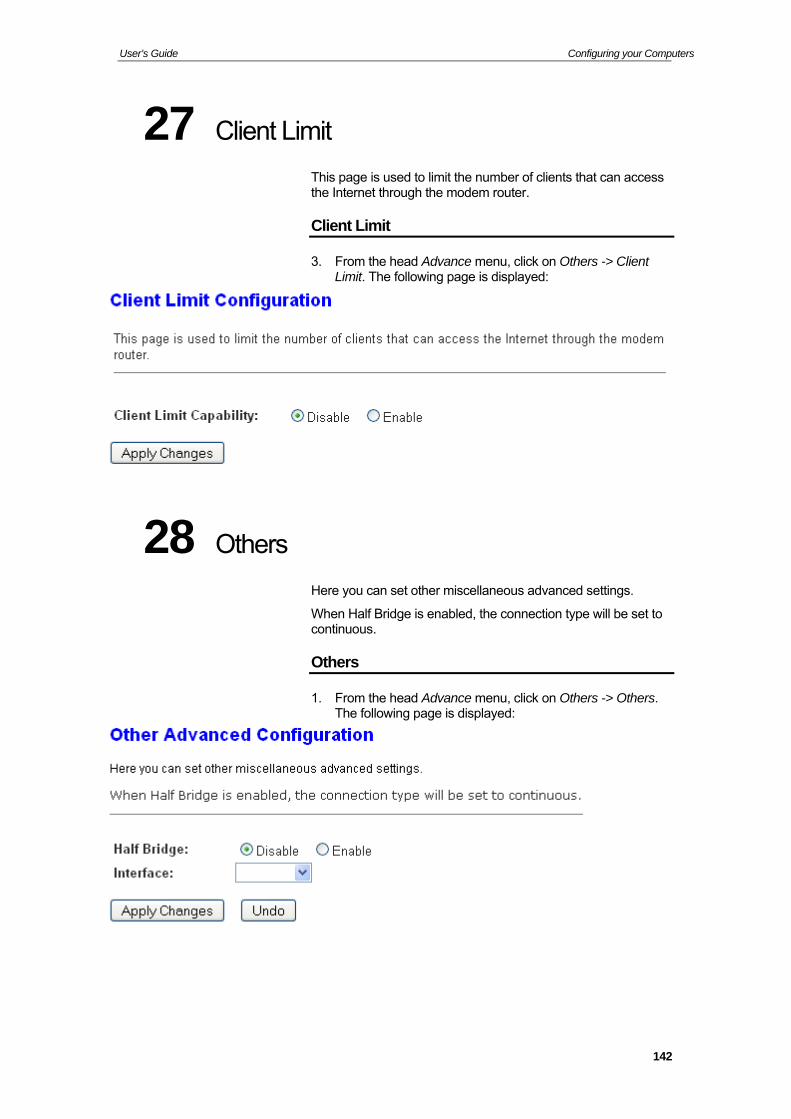
User’s Guide Configuring your Computers
27 Client Limit
This page is used to limit the number of clients that can access the Internet through the modem router.
Client Limit
3. From the head Advance menu, click on Others -> Client Limit. The following page is displayed:
28 Others
Here you can set other miscellaneous advanced settings.
When Half Bridge is enabled, the connection type will be set to continuous.
Others
1. From the head Advance menu, click on Others -> Others. The following page is displayed:
142
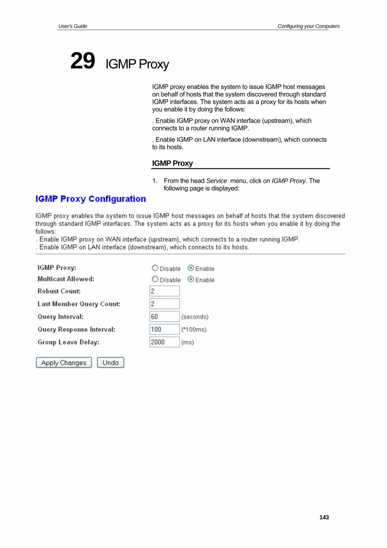
User’s Guide Configuring your Computers
29 IGMP Proxy
IGMP proxy enables the system to issue IGMP host messages on behalf of hosts that the system discovered through standard IGMP interfaces. The system acts as a proxy for its hosts when you enable it by doing the follows:
. Enable IGMP proxy on WAN interface (upstream), which connects to a router running IGMP.
. Enable IGMP on LAN interface (downstream), which connects to its hosts.
IGMP Proxy
1. From the head Service menu, click on IGMP Proxy. The following page is displayed:
143
User’s Guide Configuring your Computers
30 UPnP
UPnP is an architecture for pervasive peer-to-peer network connectivity of intelligent appliances, Wireless devices, and PCs of all form factors. It is designed to bring easy-to-use, flexible, standards-based connectivity to ad-hoc or unmanaged networks whether in the home, in a small business, public spaces, or attached to the Internet. UPnP is a distributed, open networking architecture that leverages TCP/IP and the Web technologies to enable seamless proximity networking in addition to control and data transfer among networked devices in the home, office, and public spaces.
UPnP is more than just a simple extension of the plug and play peripheral model. It is designed to support zero-configuration, "invisible" networking, and automatic discovery for a breadth of device categories from a wide range of vendors. This means a device can dynamically join a network, obtain an IP address, convey its capabilities, and learn about the presence and capabilities of other devices. DHCP and DNS servers are optional and are used only if available on the network. Finally, a device can leave a network smoothly and automatically without leaving any unwanted state behind.
The DSL device supports a control point for Universal Plug and Play (UPnP) version 1.0, and supports two key features: NAT Traversal and Device Identification. This feature requires one active WAN interface. In addition, the host should support this feature. In the presence of multiple WAN interfaces, select an interface on which the incoming traffic is present.
With NAT Traversal, when an UPnP command is received to open ports in NAT, the application translates the request into system commands to open the ports in NAT and the firewall. The interface to open the ports on is given to UPnP when it starts up and is part of the configuration of the application.
For Device Identification, the application will send a description of the DSL device as a control point back to the host making the request.
144
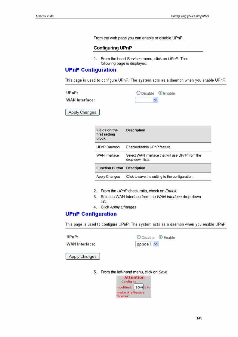
User’s Guide Configuring your Computers
From the web page you can enable or disable UPnP.
Configuring UPnP
1. From the head Services menu, click on UPnP. The following page is displayed:
Fields on the first setting block
Description
UPnP Daemon Enable/disable UPnP feature.
WAN Interface Select WAN interface that will use UPnP from the drop-down lists.
Function Button Description
Apply Changes Click to save the setting to the configuration.
2. From the UPnP check ratio, check on Enable
3. Select a WAN Interface from the WAN Interface drop-down list.
4. Click Apply Changes
5. From the left-hand menu, click on Save.
145
User’s Guide Configuring your Computers
UPnP Control Point Software on Windows ME
To install the control point software on Windows ME:
1. In the Control Panel, select "Add/Remove Programs".
2. In the "Add/Remove Programs Properties" dialog box, select the "Windows Setup" tab. In the "Components" list, double click on the "Communications" entry.
3. In the "Communications" dialog box, scroll down the "Components" list to display the UPnP entry. Select the entry, click "OK".
4. Click "OK" to finish the "Add/Remove Programs" dialog.
5. Reboot your system.
Once you have installed the UPnP software and you have rebooted (and your network includes the IGD system), you should be able to see the IGD controlled device on your network.
UPnP Control Point Software on Windows XP with Firewall
On Windows XP versions earlier than SP2, Firewall support is provided by the Windows XP Internet Connection Firewall. You cannot use the Windows XP Internet Connection Firewall support on a system that you intend to use as a UPnP control point. If this feature is enabled, although the control point system may display controlled devices in the list of network devices, the control point system cannot participate in UPnP communication. (This restriction also applies to controlled devices running on Windows XP systems earlier than SP2.)
On Windows XP SP2 and later, Firewall support is provided by Windows Firewall. Unlike earlier versions, Windows XP SP2 can be used on a system that you intend to use as a UPnP control point.
To turn off the Firewall capability on any version of Windows XP, follow the steps below:
1. In the Control Panel, select "Network and Internet Connections".
2. In the "Network and Internet Connections" dialog box, select "Network Connections".
3. In the "Network Connections" dialog box, right-click on the local area connection entry for your network; this will display a menu. Select the "Properties" menu entry.
4. In the "Local Area Connection Properties" dialog box, select the "Advanced" tab. Disable the Internet Connection Firewall by de-selecting the entry with the following label:
"Protect my computer and network by limiting or preventing access to the computer from the Internet".
5. Click "OK".
146

User’s Guide Configuring your Computers
SSDP requirements
You must have SSDP Discovery Service enabled on your Windows XP system to use the UPnP Control point software.
SSDP Discovery Service is enabled on a default installation of Windows XP. To check if it is enabled on your system, look in Control Panel > Administrative Tools > Services).
147
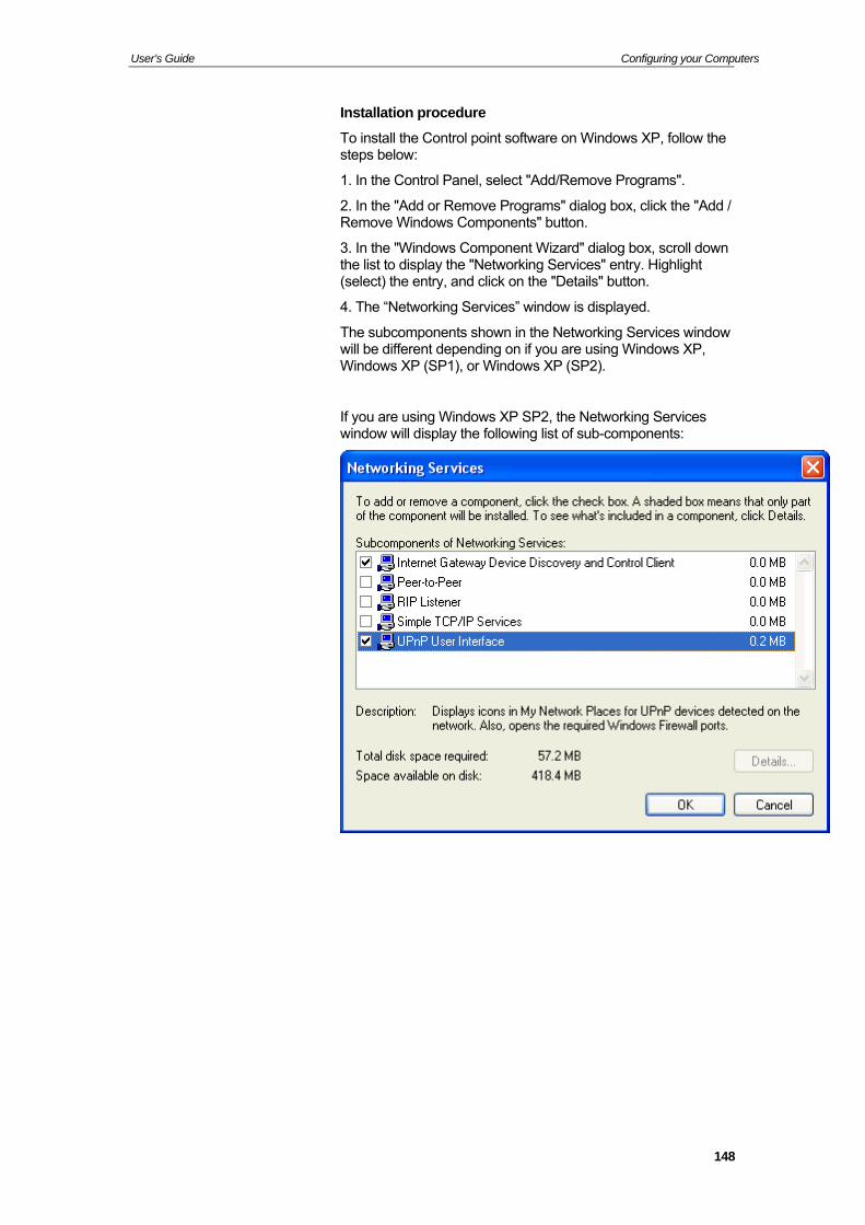
User’s Guide Configuring your Computers
Installation procedure
To install the Control point software on Windows XP, follow the steps below:
1. In the Control Panel, select "Add/Remove Programs".
2. In the "Add or Remove Programs" dialog box, click the "Add / Remove Windows Components" button.
3. In the "Windows Component Wizard" dialog box, scroll down the list to display the "Networking Services" entry. Highlight (select) the entry, and click on the "Details" button.
4. The “Networking Services” window is displayed.
The subcomponents shown in the Networking Services window will be different depending on if you are using Windows XP, Windows XP (SP1), or Windows XP (SP2).
If you are using Windows XP SP2, the Networking Services window will display the following list of sub-components:
148
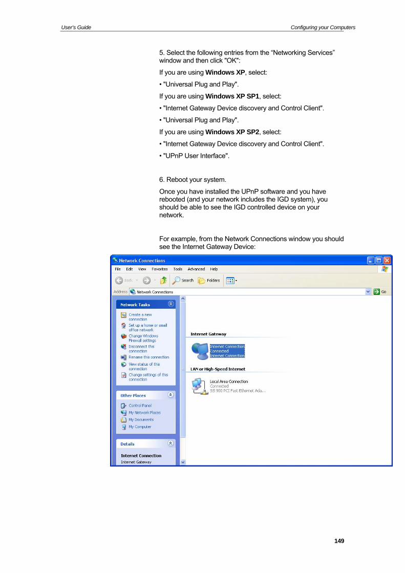
User’s Guide Configuring your Computers
5. Select the following entries from the “Networking Services” window and then click "OK":
If you are using Windows XP, select:
• "Universal Plug and Play".
If you are using Windows XP SP1, select:
• "Internet Gateway Device discovery and Control Client".
• "Universal Plug and Play".
If you are using Windows XP SP2, select:
• "Internet Gateway Device discovery and Control Client".
• "UPnP User Interface".
6. Reboot your system.
Once you have installed the UPnP software and you have rebooted (and your network includes the IGD system), you should be able to see the IGD controlled device on your network.
For example, from the Network Connections window you should see the Internet Gateway Device:
149
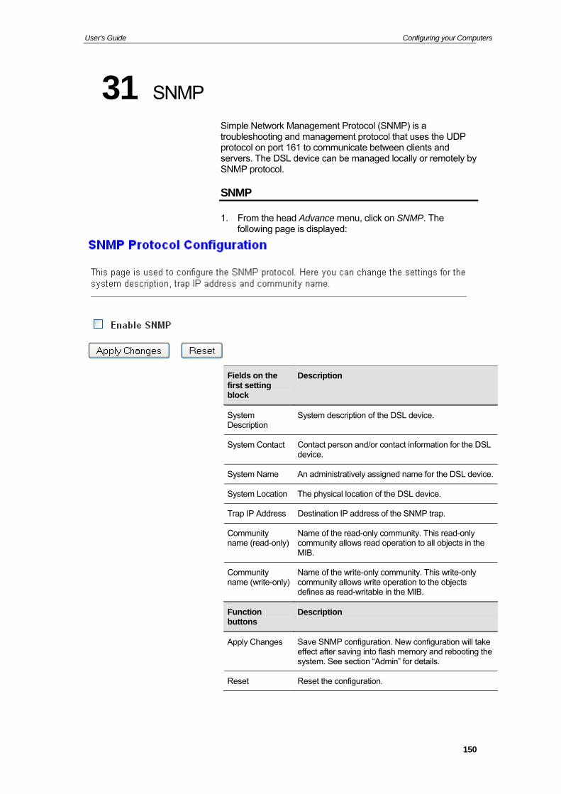
User’s Guide Configuring your Computers
31 SNMP
Simple Network Management Protocol (SNMP) is a troubleshooting and management protocol that uses the UDP protocol on port 161 to communicate between clients and servers. The DSL device can be managed locally or remotely by SNMP protocol.
SNMP
1. From the head Advance menu, click on SNMP. The following page is displayed:
Fields on the first setting block
Description
System Description
System description of the DSL device.
System Contact Contact person and/or contact information for the DSL device.
System Name An administratively assigned name for the DSL device.
System Location The physical location of the DSL device.
Trap IP Address Destination IP address of the SNMP trap.
Community name (read-only)
Name of the read-only community. This read-only community allows read operation to all objects in the MIB.
Community name (write-only)
Name of the write-only community. This write-only community allows write operation to the objects defines as read-writable in the MIB.
Function buttons
Description
Apply Changes Save SNMP configuration. New configuration will take effect after saving into flash memory and rebooting the system. See section “Admin” for details.
Reset Reset the configuration.
150
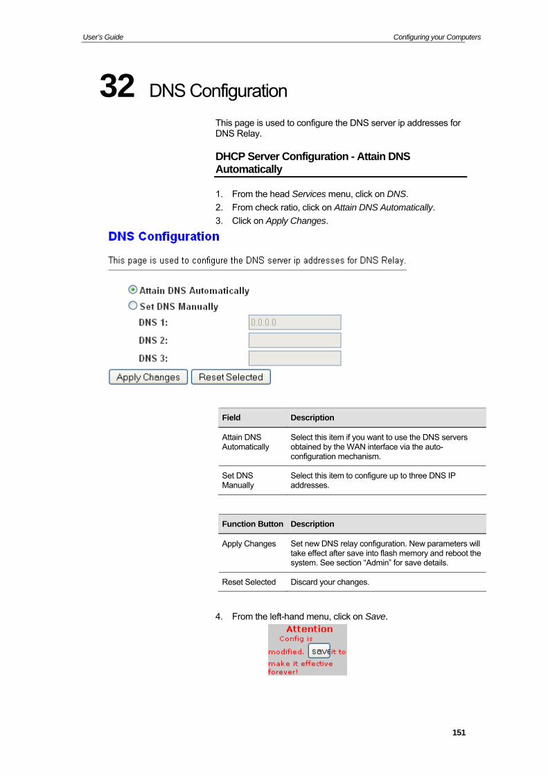
User’s Guide Configuring your Computers
32 DNS Configuration
This page is used to configure the DNS server ip addresses for DNS Relay.
DHCP Server Configuration - Attain DNS Automatically
1. From the head Services menu, click on DNS.
2. From check ratio, click on Attain DNS Automatically.
3. Click on Apply Changes.
Field Description
Attain DNS Automatically
Select this item if you want to use the DNS servers obtained by the WAN interface via the auto-configuration mechanism.
Set DNS Manually
Select this item to configure up to three DNS IP addresses.
Function Button Description
Apply Changes Set new DNS relay configuration. New parameters will take effect after save into flash memory and reboot the system. See section “Admin” for save details.
Reset Selected Discard your changes.
4. From the left-hand menu, click on Save.
151
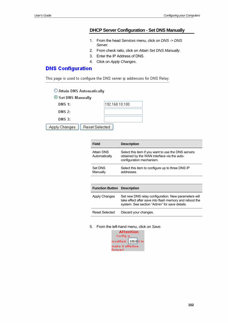
User’s Guide Configuring your Computers
DHCP Server Configuration - Set DNS Manually
1. From the head Services menu, click on DNS -> DNS Server.
2. From check ratio, click on Attain Set DNS Manually.
3. Enter the IP Address of DNS.
4. Click on Apply Changes.
Field Description
Attain DNS Automatically
Select this item if you want to use the DNS servers obtained by the WAN interface via the auto-configuration mechanism.
Set DNS Manually
Select this item to configure up to three DNS IP addresses.
Function Button Description
Apply Changes Set new DNS relay configuration. New parameters will take effect after save into flash memory and reboot the system. See section “Admin” for save details.
Reset Selected Discard your changes.
5. From the left-hand menu, click on Save.
152
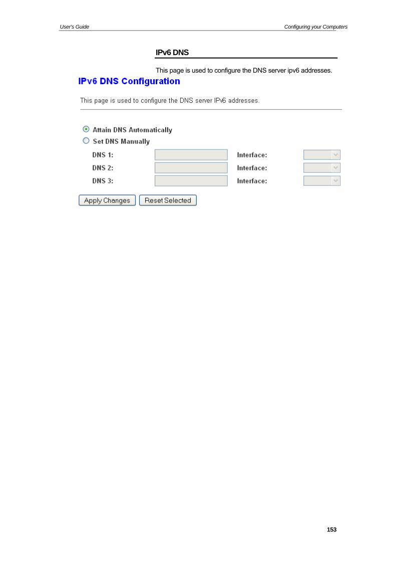
User’s Guide Configuring your Computers
IPv6 DNS
This page is used to configure the DNS server ipv6 addresses.
153
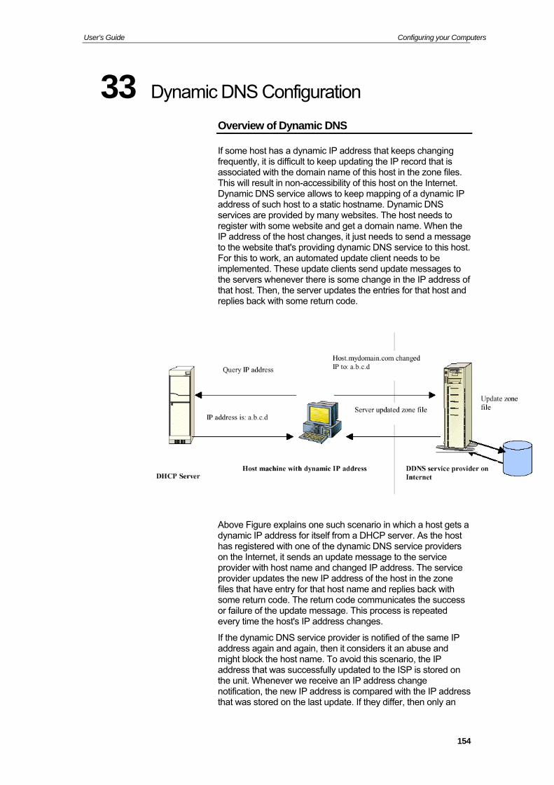
User’s Guide Configuring your Computers
33 Dynamic DNS Configuration
Overview of Dynamic DNS
If some host has a dynamic IP address that keeps changing frequently, it is difficult to keep updating the IP record that is associated with the domain name of this host in the zone files. This will result in non-accessibility of this host on the Internet. Dynamic DNS service allows to keep mapping of a dynamic IP address of such host to a static hostname. Dynamic DNS services are provided by many websites. The host needs to register with some website and get a domain name. When the IP address of the host changes, it just needs to send a message to the website that's providing dynamic DNS service to this host. For this to work, an automated update client needs to be implemented. These update clients send update messages to the servers whenever there is some change in the IP address of that host. Then, the server updates the entries for that host and replies back with some return code.
Above Figure explains one such scenario in which a host gets a dynamic IP address for itself from a DHCP server. As the host has registered with one of the dynamic DNS service providers on the Internet, it sends an update message to the service provider with host name and changed IP address. The service provider updates the new IP address of the host in the zone files that have entry for that host name and replies back with some return code. The return code communicates the success or failure of the update message. This process is repeated every time the host's IP address changes.
If the dynamic DNS service provider is notified of the same IP address again and again, then it considers it an abuse and might block the host name. To avoid this scenario, the IP address that was successfully updated to the ISP is stored on the unit. Whenever we receive an IP address change notification, the new IP address is compared with the IP address that was stored on the last update. If they differ, then only an
154
User’s Guide Configuring your Computers
update request is sent. However, when the system comes up there is no way of knowing what was the IP address on last successful update before the system went down. You need to give the command “system config save“ periodically to save this IP address on Flash.
Registering With Dynamic DNS Service Provider
Currently, Wireless ADSL2+ Router supports two Dynamic DNS service providers, www.tzo.com and www.dyndns.com. To use their Dynamic DNS service, you first need to visit the Web site of a service provider and register. While registering, you need to provide your username, password, and hostname as mandatory parameters. A service provider may also prompt you to fill some optional parameters.
Configuring IP Interfaces
You need to create a Dynamic DNS interface per IP interface and can only create one Dynamic DNS interface service on one IP interface. For more information on creating IP interfaces, refer to section Creating IP interfaces.
Note
www.dyndns.org provides three kinds of services - Dynamic DNS, Custom DNS and Static DNS. You can create different domains in these systems. Custom DNS service is a full DNS solution for newly purchased domains or domains you already own. A web-based interface provides complete control over resource records and your entire domain, including support for dynamic IPs and automated updates. Static DNS service points a DNS hostname in some domain owned by dyndns.org to the user's ISP-assigned static or pseudo-static IP address.
DynDNS service points a fixed hostname in some domain owned by dyndns.org to the user's ISP-assigned dynamic IP address. This allows more frequent update of IP addresses, than allowed by Static DNS.
155
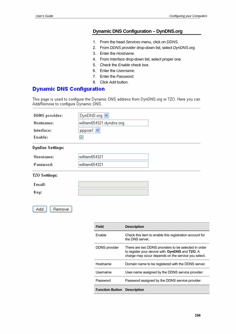
User’s Guide Configuring your Computers
Dynamic DNS Configuration – DynDNS.org
1. From the head Services menu, click on DDNS.
2. From DDNS provider drop-down list, select DynDNS.org.
3. Enter the Hostname.
4. From Interface drop-down list, select proper one.
5. Check the Enable check box.
6. Enter the Username.
7. Enter the Password.
8. Click Add button.
Field Description
Enable Check this item to enable this registration account for the DNS server.
DDNS provider There are two DDNS providers to be selected in order to register your device with: DynDNS and TZO. A charge may occur depends on the service you select.
Hostname Domain name to be registered with the DDNS server.
Username User-name assigned by the DDNS service provider.
Password Password assigned by the DDNS service provider.
Function Button Description
156
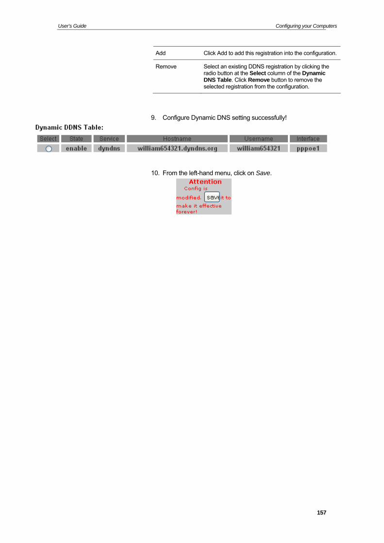
User’s Guide Configuring your Computers
Add Click Add to add this registration into the configuration.
Remove Select an existing DDNS registration by clicking the radio button at the Select column of the Dynamic DNS Table. Click Remove button to remove the selected registration from the configuration.
9. Configure Dynamic DNS setting successfully!
10. From the left-hand menu, click on Save.
157
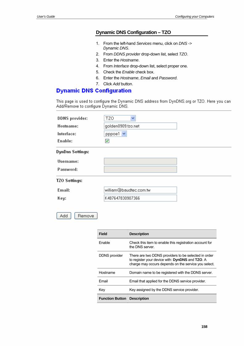
User’s Guide Configuring your Computers
Dynamic DNS Configuration – TZO
1. From the left-hand Services menu, click on DNS -> Dynamic DNS.
2. From DDNS provider drop-down list, select TZO.
3. Enter the Hostname.
4. From Interface drop-down list, select proper one.
5. Check the Enable check box.
6. Enter the Hostname, Email and Password.
7. Click Add button.
Field Description
Enable Check this item to enable this registration account for the DNS server.
DDNS provider There are two DDNS providers to be selected in order to register your device with: DynDNS and TZO. A charge may occurs depends on the service you select.
Hostname Domain name to be registered with the DDNS server.
Email Email that applied for the DDNS service provider.
Key Key assigned by the DDNS service provider.
Function Button Description
158
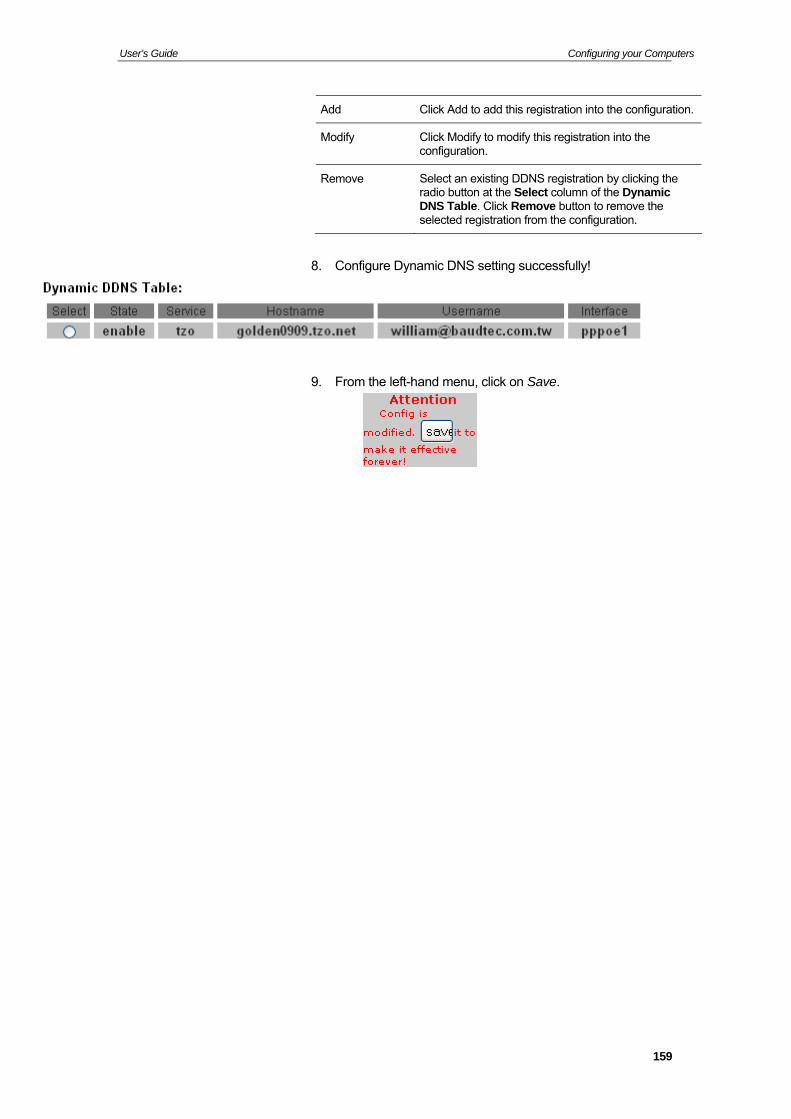
User’s Guide Configuring your Computers
Add Click Add to add this registration into the configuration.
Modify Click Modify to modify this registration into the configuration.
Remove Select an existing DDNS registration by clicking the radio button at the Select column of the Dynamic DNS Table. Click Remove button to remove the selected registration from the configuration.
8. Configure Dynamic DNS setting successfully!
9. From the left-hand menu, click on Save.
159
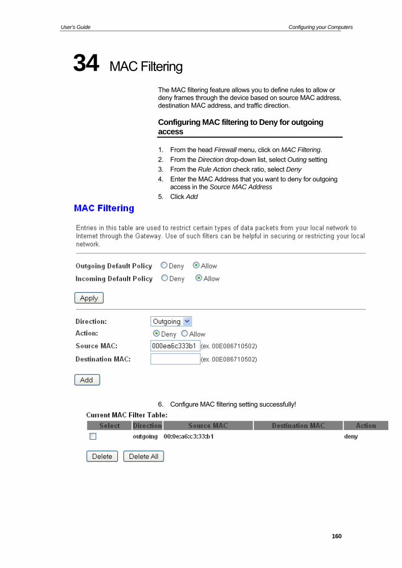
User’s Guide Configuring your Computers
34 MAC Filtering
The MAC filtering feature allows you to define rules to allow or deny frames through the device based on source MAC address, destination MAC address, and traffic direction.
Configuring MAC filtering to Deny for outgoing access
1. From the head Firewall menu, click on MAC Filtering.
2. From the Direction drop-down list, select Outing setting
3. From the Rule Action check ratio, select Deny
4. Enter the MAC Address that you want to deny for outgoing access in the Source MAC Address
5. Click Add
6. Configure MAC filtering setting successfully!
160
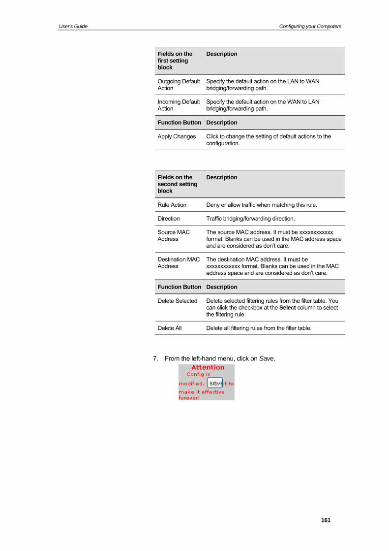
User’s Guide Configuring your Computers
Fields on the first setting block
Description
Outgoing Default Action
Specify the default action on the LAN to WAN bridging/forwarding path.
Incoming Default Action
Specify the default action on the WAN to LAN bridging/forwarding path.
Function Button Description
Apply Changes Click to change the setting of default actions to the configuration.
Fields on the second setting block
Description
Rule Action Deny or allow traffic when matching this rule.
Direction Traffic bridging/forwarding direction.
Source MAC Address
The source MAC address. It must be xxxxxxxxxxxx format. Blanks can be used in the MAC address space and are considered as don’t care.
Destination MAC Address
The destination MAC address. It must be xxxxxxxxxxxx format. Blanks can be used in the MAC address space and are considered as don’t care.
Function Button Description
Delete Selected Delete selected filtering rules from the filter table. You can click the checkbox at the Select column to select the filtering rule.
Delete All Delete all filtering rules from the filter table.
7. From the left-hand menu, click on Save.
161
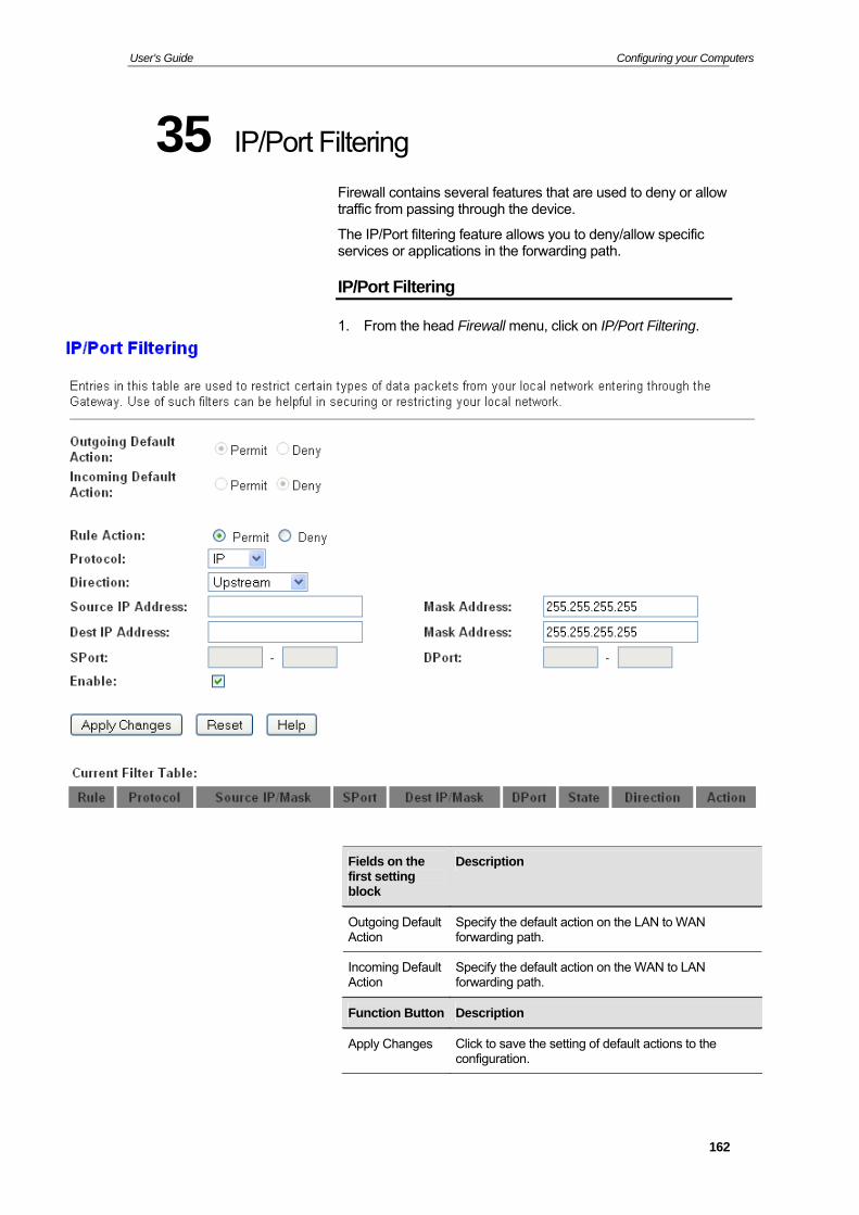
User’s Guide Configuring your Computers
35 IP/Port Filtering
Firewall contains several features that are used to deny or allow traffic from passing through the device.
The IP/Port filtering feature allows you to deny/allow specific services or applications in the forwarding path.
IP/Port Filtering
1. From the head Firewall menu, click on IP/Port Filtering.
Fields on the first setting block
Description
Outgoing Default Action
Specify the default action on the LAN to WAN forwarding path.
Incoming Default Action
Specify the default action on the WAN to LAN forwarding path.
Function Button Description
Apply Changes Click to save the setting of default actions to the configuration.
162
User’s Guide Configuring your Computers
Fields on the second setting block
Description
Rule Action Deny or allow traffic when matching this rule.
Direction Traffic forwarding direction.
Protocol There are 3 options available: TCP, UDP and ICMP.
Source IP Address
The source IP address assigned to the traffic on which filtering is applied.
Source Subnet Mask
Subnet-mask of the source IP.
Source Port Starting and ending source port numbers.
Destination IP Address
The destination IP address assigned to the traffic on which filtering is applied.
Destination Subnet Mask
Subnet-mask of the destination IP.
Destination Port Starting and ending destination port numbers.
Function Button Description
Apply Changes Click to save the rule entry to the configuration.
Delete Selected Delete selected filtering rules from the filter table. You can click the checkbox at the Select column to select the filtering rule.
Delete All Delete all filtering rules from the filter table.
163
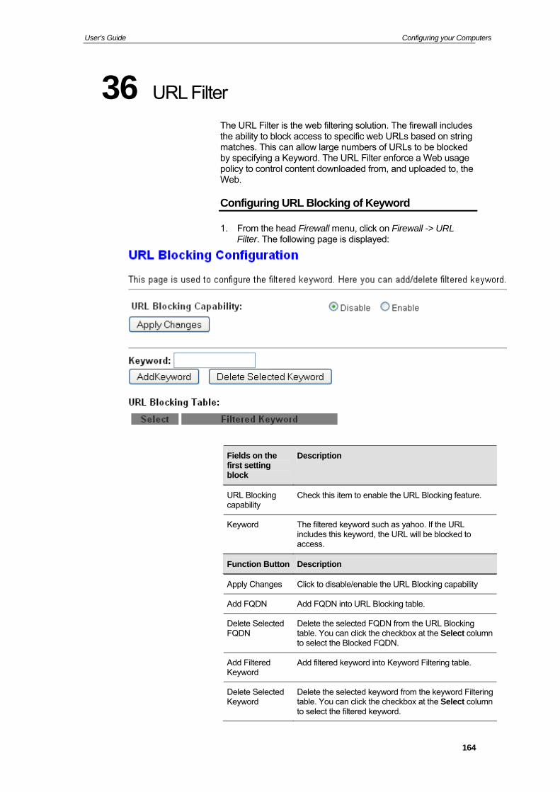
User’s Guide Configuring your Computers
36 URL Filter
The URL Filter is the web filtering solution. The firewall includes the ability to block access to specific web URLs based on string matches. This can allow large numbers of URLs to be blocked by specifying a Keyword. The URL Filter enforce a Web usage policy to control content downloaded from, and uploaded to, the Web.
Configuring URL Blocking of Keyword
1. From the head Firewall menu, click on Firewall -> URL Filter. The following page is displayed:
Fields on the first setting block
Description
URL Blocking capability
Check this item to enable the URL Blocking feature.
Keyword The filtered keyword such as yahoo. If the URL includes this keyword, the URL will be blocked to access.
Function Button Description
Apply Changes Click to disable/enable the URL Blocking capability
Add FQDN Add FQDN into URL Blocking table.
Delete Selected FQDN
Delete the selected FQDN from the URL Blocking table. You can click the checkbox at the Select column to select the Blocked FQDN.
Add Filtered Keyword
Add filtered keyword into Keyword Filtering table.
Delete Selected Keyword
Delete the selected keyword from the keyword Filtering table. You can click the checkbox at the Select column to select the filtered keyword.
164
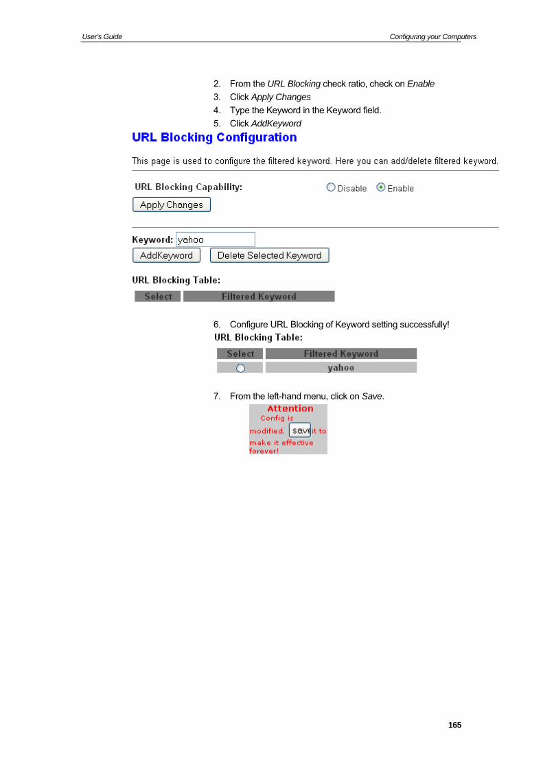
User’s Guide Configuring your Computers
2. From the URL Blocking check ratio, check on Enable
3. Click Apply Changes
4. Type the Keyword in the Keyword field.
5. Click AddKeyword
6. Configure URL Blocking of Keyword setting successfully!
7. From the left-hand menu, click on Save.
165
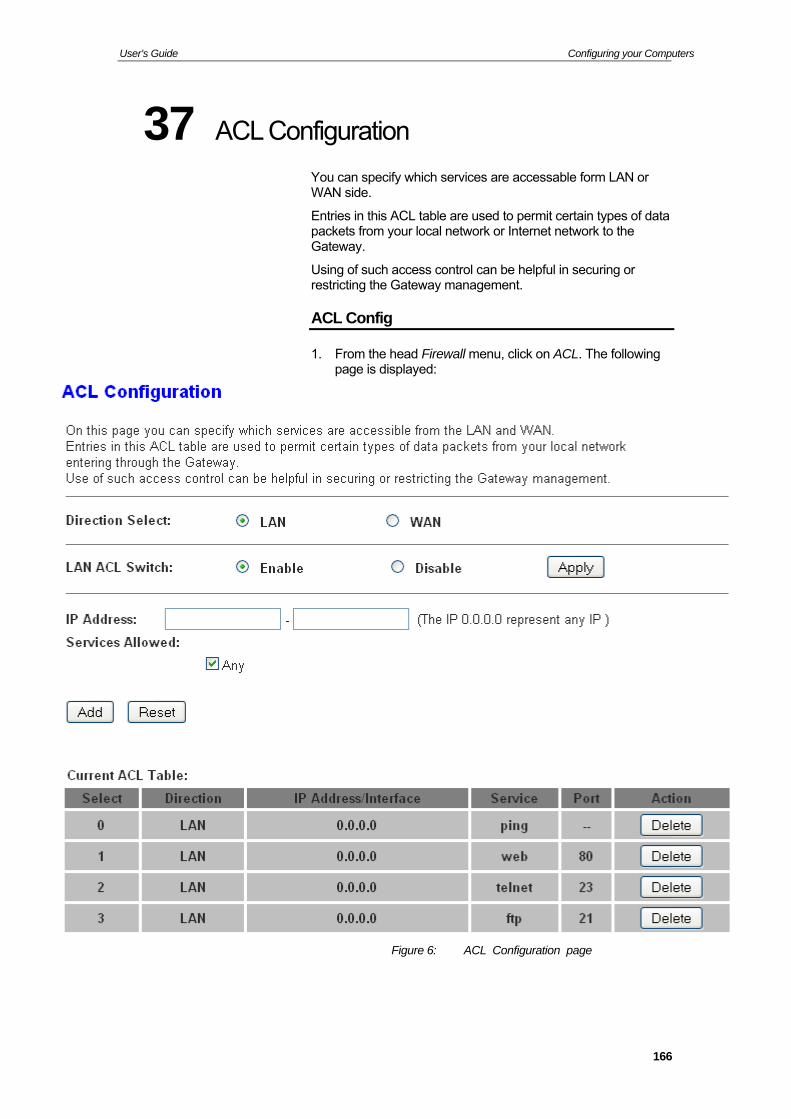
User’s Guide Configuring your Computers
37 ACL Configuration
You can specify which services are accessable form LAN or WAN side.
Entries in this ACL table are used to permit certain types of data packets from your local network or Internet network to the Gateway.
Using of such access control can be helpful in securing or restricting the Gateway management.
ACL Config
1. From the head Firewall menu, click on ACL. The following page is displayed:
Figure 6: ACL Configuration page
166
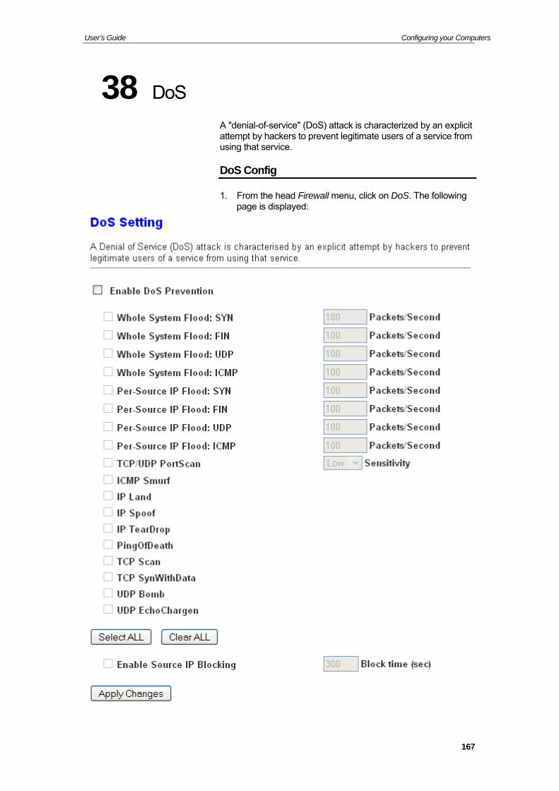
User’s Guide Configuring your Computers
38 DoS
A "denial-of-service" (DoS) attack is characterized by an explicit attempt by hackers to prevent legitimate users of a service from using that service.
DoS Config
1. From the head Firewall menu, click on DoS. The following page is displayed:
167
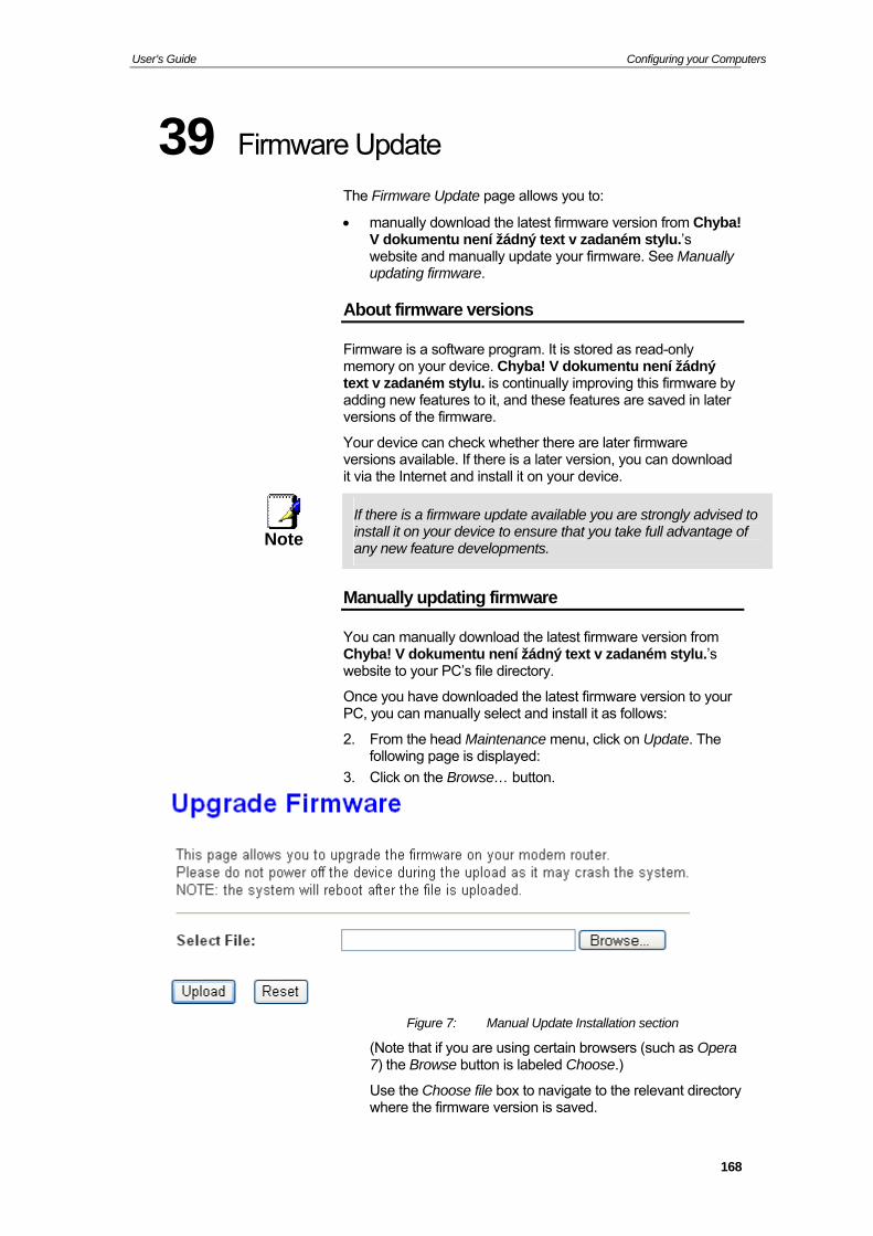
User’s Guide Configuring your Computers
39 Firmware Update
The Firmware Update page allows you to:
manually download the latest firmware version from Chyba! V dokumentu není žádný text v zadaném stylu.’s website and manually update your firmware. See Manually updating firmware.
About firmware versions
Firmware is a software program. It is stored as read-only memory on your device. Chyba! V dokumentu není žádný text v zadaném stylu. is continually improving this firmware by adding new features to it, and these features are saved in later versions of the firmware.
Your device can check whether there are later firmware versions available. If there is a later version, you can download it via the Internet and install it on your device.
If there is a firmware update available you are strongly advised to install it on your device to ensure that you take full advantage of Note
any new feature developments.
Manually updating firmware
You can manually download the latest firmware version from Chyba! V dokumentu není žádný text v zadaném stylu.’s website to your PC’s file directory.
Once you have downloaded the latest firmware version to your PC, you can manually select and install it as follows:
2. From the head Maintenance menu, click on Update. The following page is displayed:
3. Click on the Browse… button.
Figure 7: Manual Update Installation section
(Note that if you are using certain browsers (such as Opera 7) the Browse button is labeled Choose.)
Use the Choose file box to navigate to the relevant directory where the firmware version is saved.
168
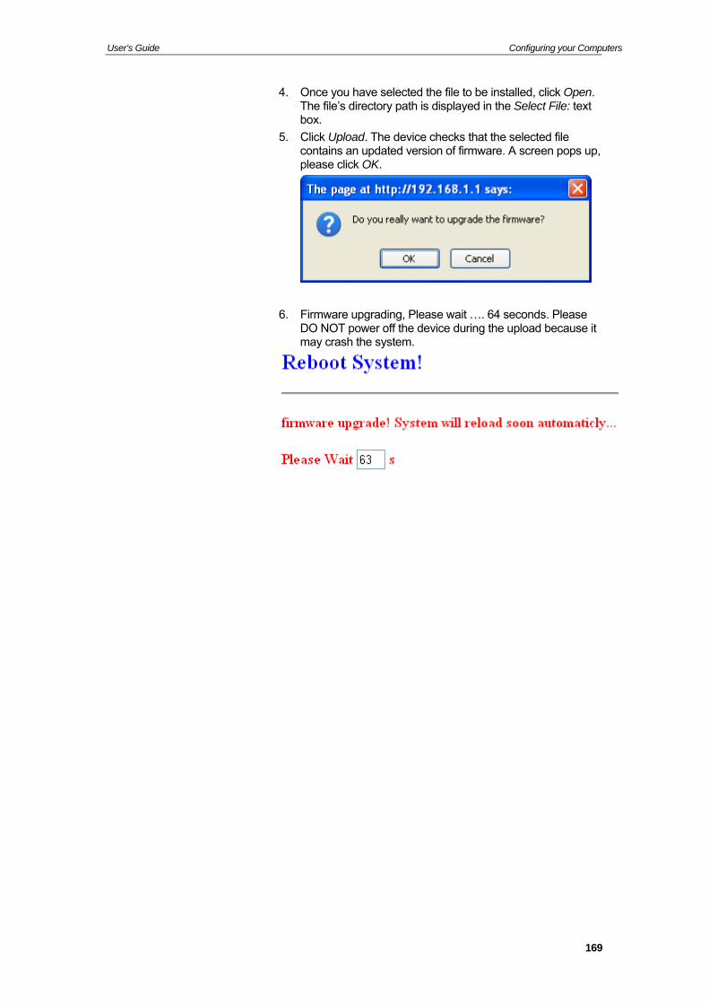
User’s Guide Configuring your Computers
4. Once you have selected theThe file’s directory path is d
file to be installed, click Open. isplayed in the Select File: text
box.
5. Click Upload. The device checks that the selected file contains an updated version of firmware. A screen pops up, please click OK.
6. Firmware upgrading, Please waDO NOT power off the device d
it …. 64 seconds. Please uring the upload because it
may crash the system.
169

User’s Guide Configuring your Computers
7. Firmware update has been update complete and it will bring you to the home page of the device:
170

User’s Guide Configuring your Computers
171

User’s Guide Configuring your Computers
8. From the head Maintenance menu, click on Reboot. The following page is displayed:
9. From the Reboot from drop-down list, select Factory Default Configuration
10. Click on Commit Changes.
11. Please wait for 64 seconds to let the system reboot.
172
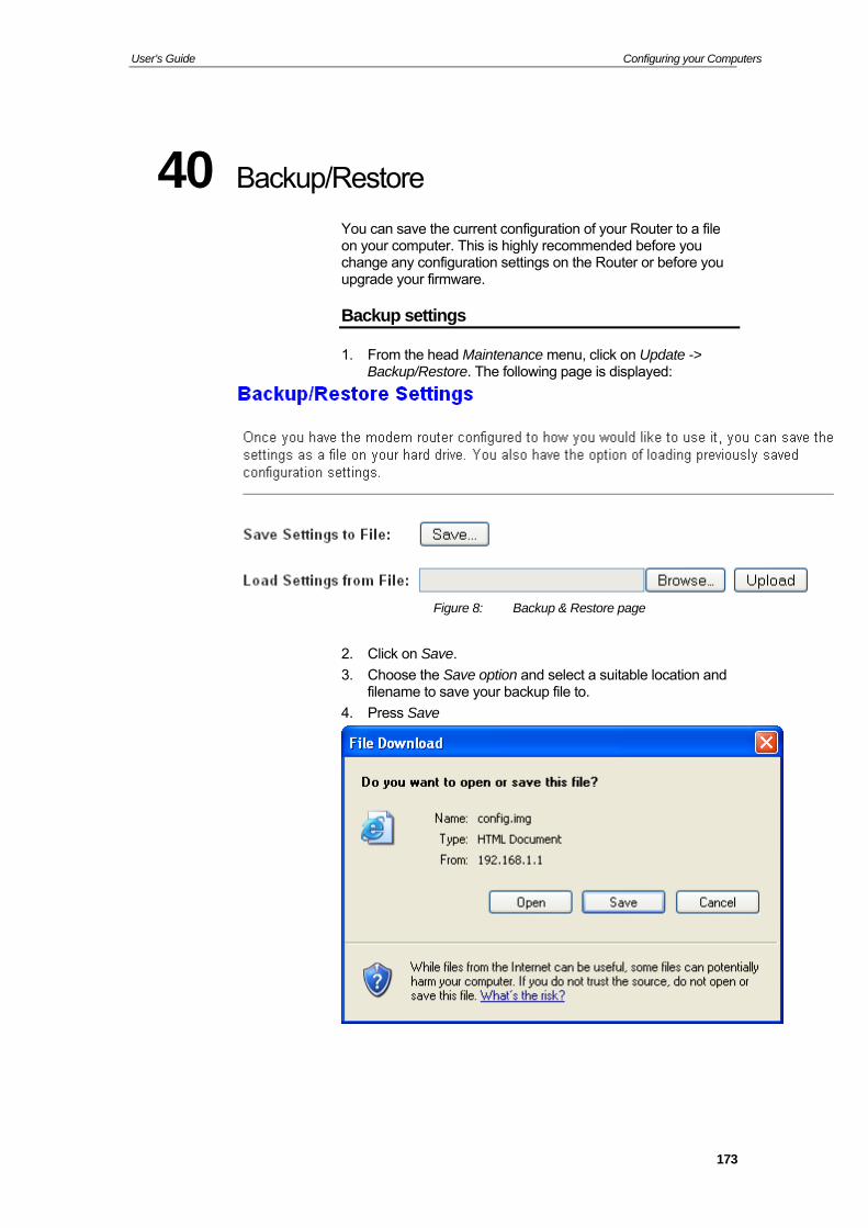
User’s Guide Configuring your Computers
40 Bac
You can save the current configuration of your Router to a file on your computer. This is highly recommended before you change any configuration settings on the Router or before you upgrade your firmware.
Backup settings
kup/Restore
1. From the head Maintenance menu, click on Update -> Backup/Restore. The following page is displayed:
Figure 8: Backup & Restore page
. Click on Save.
. Choose the Save option and select a suitable location and filename to save your backup file to.
. Press Save
2
3
4
173
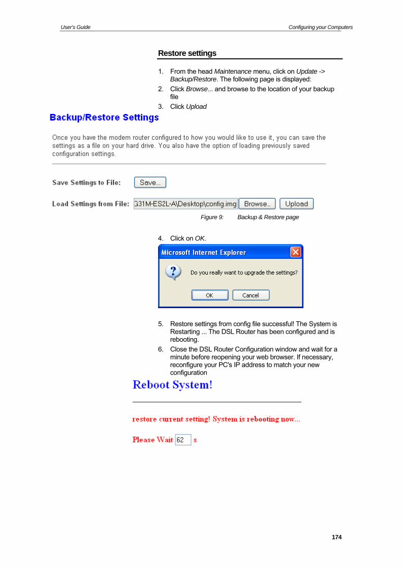
User’s Guide Configuring your Computers
Restore settings
1. From the head Maintenance menu, click on Update -> store. The following page is displayed:
se... and browse to the location of your backup file
Backup/Re
2. Click Brow
3. Click Upload
Figure 9: Backup & Restore page
4. Click on OK.
5. Restore settings from config file successful! The System is The DSL Router has been configured and is
rebooting.
6. Close the DSL Router Configuration window and wait for a minute before reopening your web browser. If necessary, reconfigure your PC's IP address to match your new configuration
Restarting ...
174
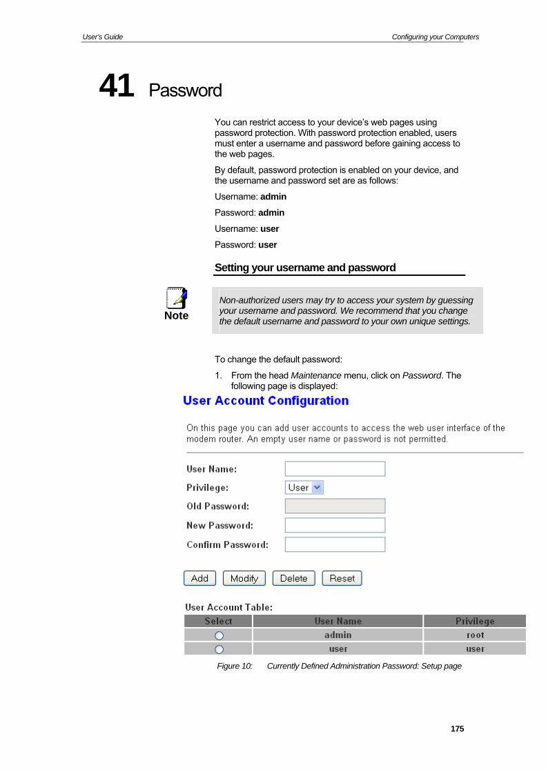
User’s Guide Configuring your Computers
41 Password
protection. With password protection enabled, users ame and password before gaining access to
the web pages.
By default, password protection is enabled on your device, and the username and password set are as follows:
Username: admin
Password: admin
Username: user
Password: user
Setting your username and password
You can restrict access to your device’s web pages using passwordmust enter a usern
Non-a m by guessing uthorized users may try to access your systeyour username and password. We recommend that you change Note the default username and password to your own unique settings.
To change the default password:
1. From the head Maintenance menu, click on Password. The following page is displayed:
Figure 10: Currently Defined Administration Password: Setup page
175
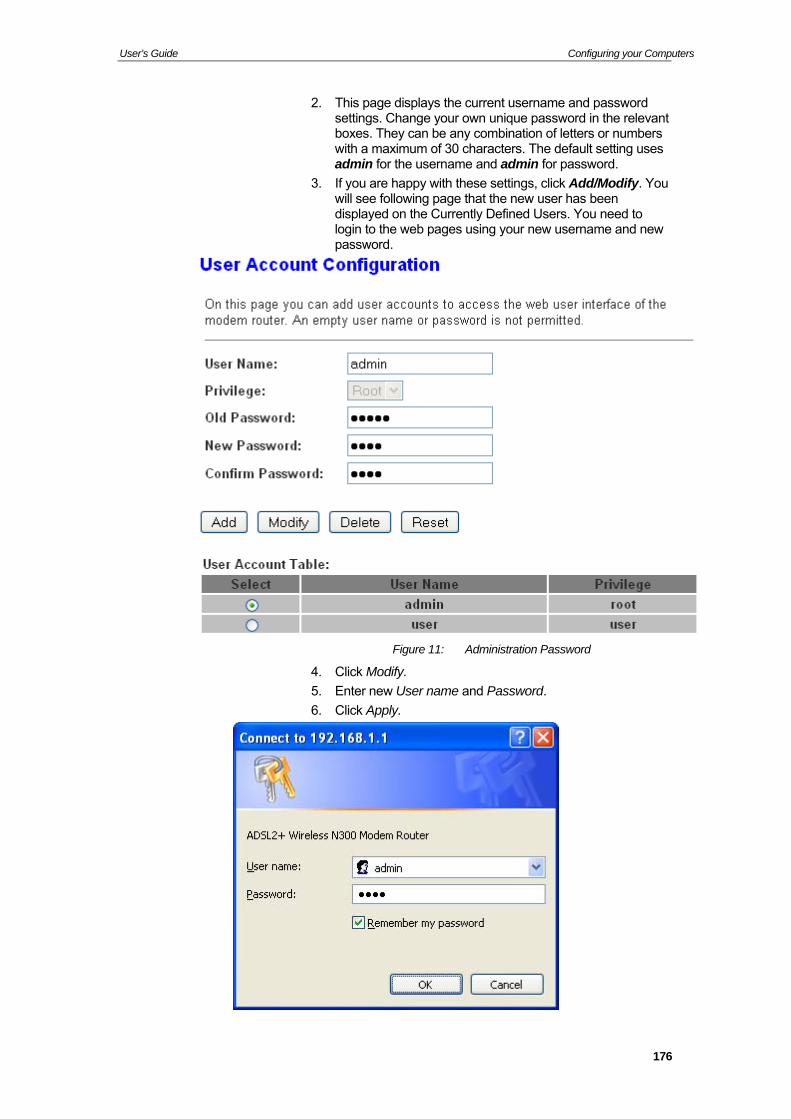
User’s Guide Configuring your Computers
2. This page displays the current username and password settings. Change your own unique password in the relevant boxes. They can be any combination of letters or numbers with a maximum of 30 characters. The default setting uses admin for the username and admin for password.
eb pages using your new username and new
3. If you are happy with these settings, click Add/Modify. Youwill see following page that the new user has been displayed on the Currently Defined Users. You need to login to the wpassword.
Figure 11: Administration Password
4. Click Modify.
5. Enter new User name and Password.
6. Click Apply.
176
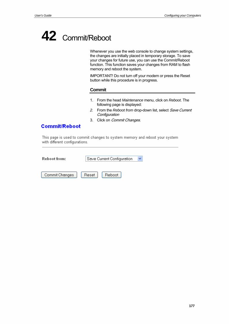
User’s Guide Configuring your Computers
42 Comm
t
IMPORTANT! Do not turn off your modem or press the Reset button while this procedure is in progress.
Commit
it/Reboot
Whenever you use the web console to change system settings, the changes are initially placed in temporary storage. To save your changes for future use, you can use the Commit/Reboofunction. This function saves your changes from RAM to flash memory and reboot the system.
1. From the head Maintenance menu, click on Reboot. The following page is displayed:
2. From the Reboot from drop-down list, select Save Current Configuration
3. Click on Commit Changes.
177
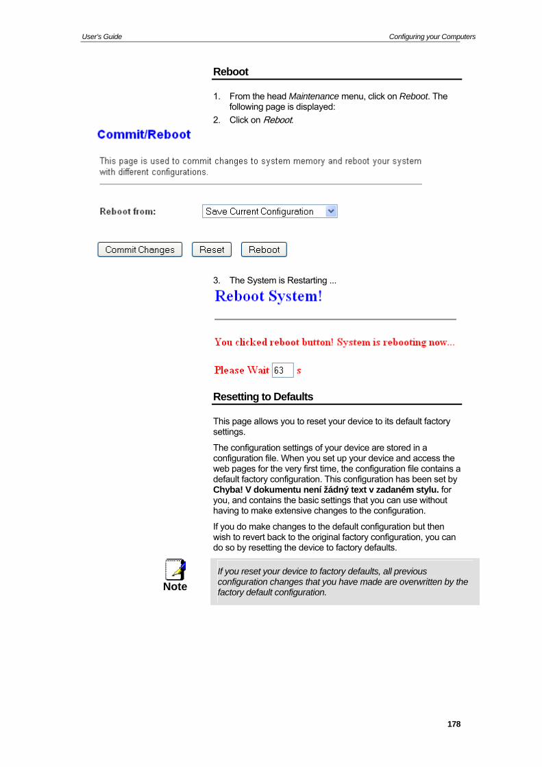
User’s Guide Configuring your Computers
Reboot
1. From the head Maintenance menu, click on Reboot. The following page is displayed:
2. Click on Reboot.
3. The System is Restarting ...
Resetting to Defaults
This page allows you to reset your device to its default factory settings.
The configu ion settings of your device are stored in a configuratio file. When you set up your device and access the web pages f r the very first time, the configuration file contains a default facto y configuration. This configuration has been set by Chyba! V d kumentu není žádný text v zadaném stylu. for you, and co tains the basic settings that you can use without having to make extensive changes to the configuration.
If you do make changes to the default configuration but then wish to reve back to the original factory configuration, you can do so by re ting the device to factory defaults.
ratnoron
rtset
If you rese your device to factory defaults, all previous t configurati n changes that you have made are overwritten by the oNote
factory def ult configuration.
a
178
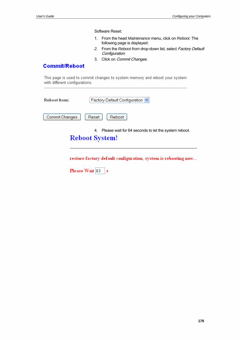
User’s Guide Configuring your Computers
Software Reset:
1. From the head Maintenance menu, click on Reboot. The
own list, select Factory Default
3. Click on Commit Changes.
following page is displayed:
2. From the Reboot from drop-dConfiguration
4. Please wait for 64 seconds to let the system reboot.
179
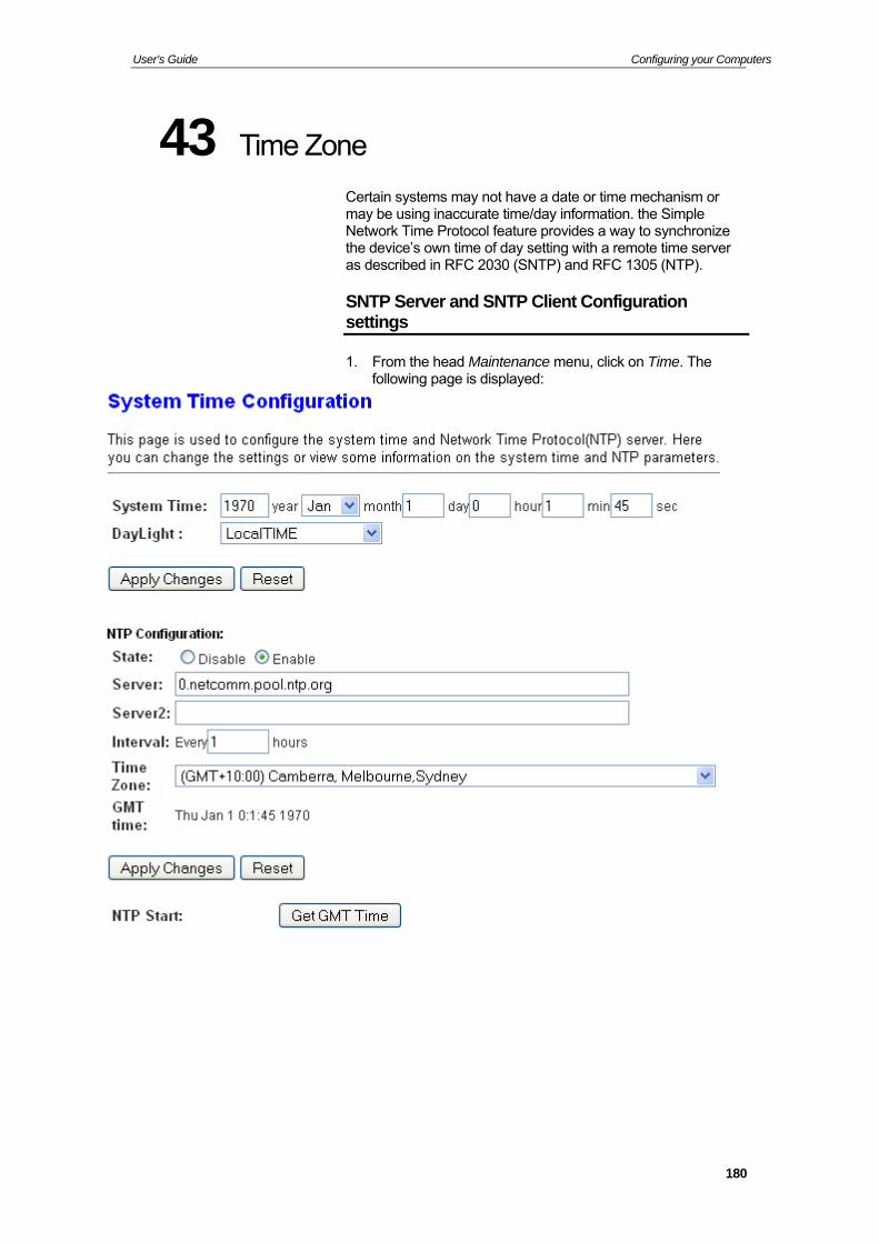
User’s Guide Configuring your Computers
43 Tim
ay not have a date or time mechanism or information. the Simple
Network Time Protocol feature provides a way to synchronize the device’s own time of day setting with a remote time server as described in RFC 2030 (SNTP) and RFC 1305 (NTP).
SNTP Server and SNTP Client Configuration settings
e Zone
Certain systems mmay be using inaccurate time/day
1. From the head Maintenance menu, click on Time. The following page is displayed:
180
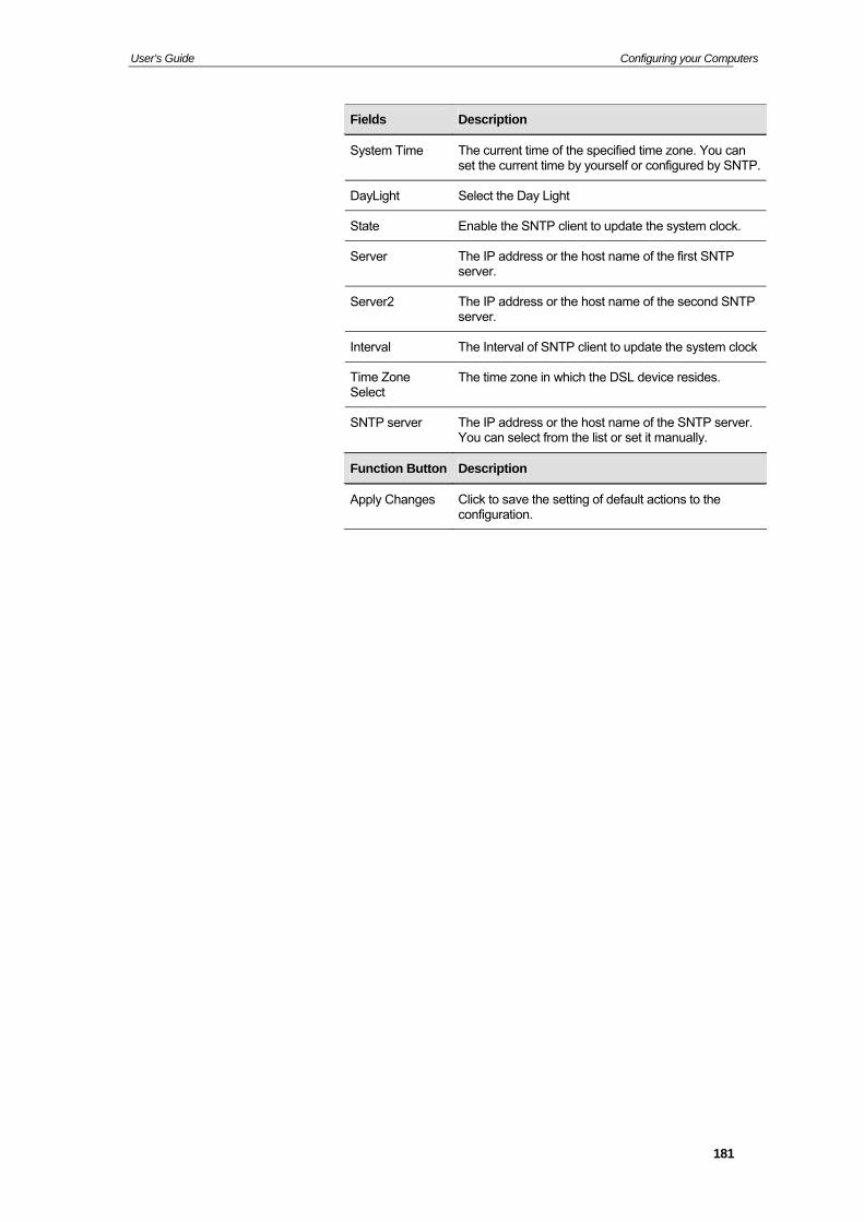
User’s Guide Configuring your Computers
Fields Description
System Time The current time of the specified time zone. You can set the current time by yourself or configured by SNTP.
DayLight Select the Day Light
State Enable the SNTP client to update the system clo
ck.
Server The IP address or the host name of the first SNTserver.
P
Server2 The IP address or the host name of the second SNTP server.
Interval The Interval of SNTP client to update the system clock
Time Zone The time zone iSelect
n which the DSL device resides.
SNTP server The IP address or the host name of the SNTP server. You can select from the list or set it manually.
Function Button Description
Apply Changes Click to save the setting of default actions to the configuration.
181
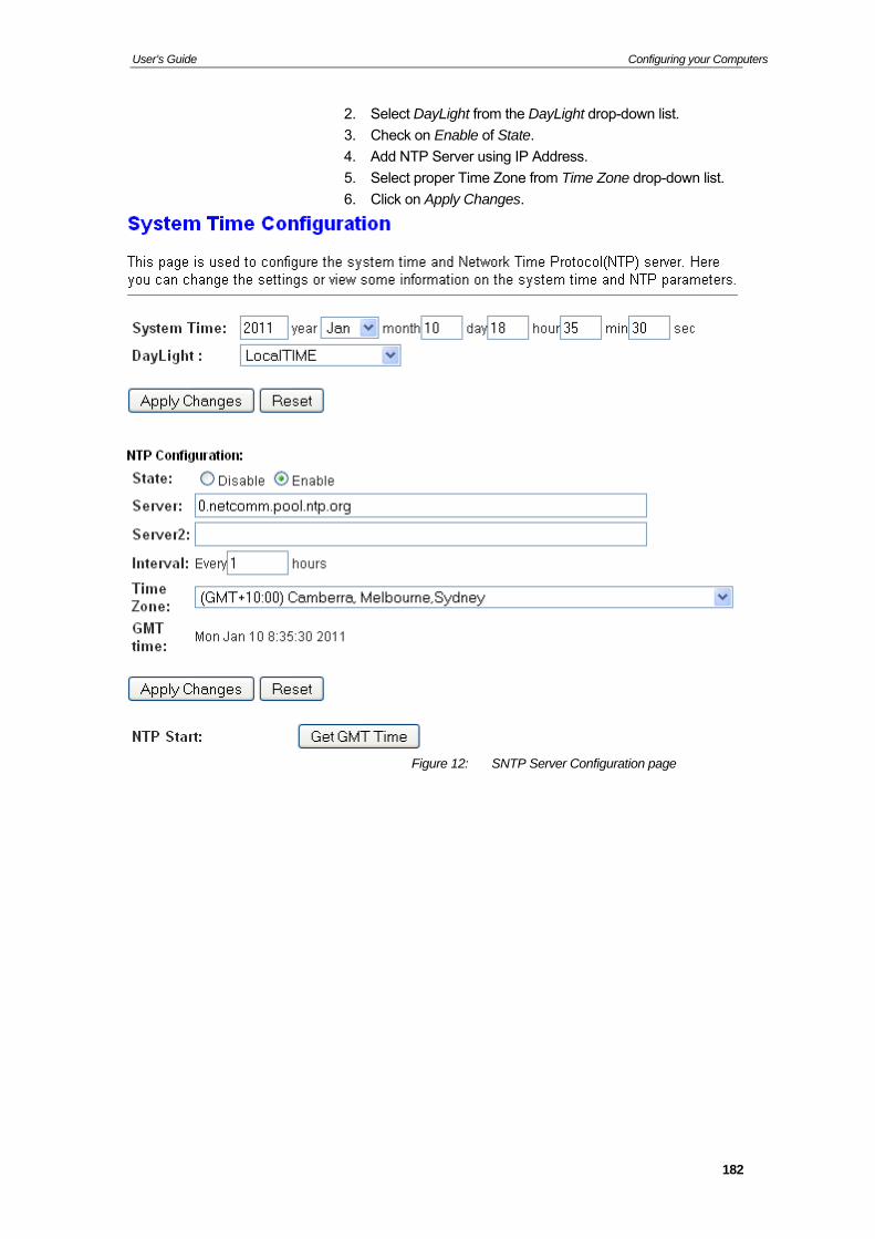
User’s Guide Configuring your Computers
2. ct DayLigh yLight drop-down list.
. Check on Enable of State.
erv
. Select proper T
n Apply
Sele t from the Da
3
4. Add NTP S er using IP Address.
ime Zone from Time Zone drop-down list. 5
6. Click o Changes.
Figure 12: SNTP Server Configuration page
182
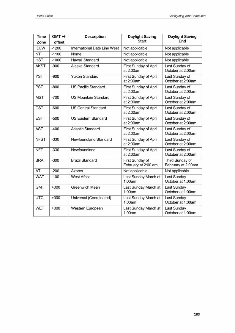
User’s Guide Configuring your Computers
Time
Zone
GMT +/-
offset
aving Daylight Saving End
Description Daylight SStart
IDLW -1200 International Date Line West Not applicable Not applicable
NT -1100 No ble Not applicable me Not applica
HST -1000 Hawaii Standard Not applicable Not applicable
AKST -900 Alaska Standard First Sunday of April at 2:00am
Last Sunday of October at 2:00am
YST -900 Yukon Standard First Sunday of April at 2:00am
Last Sunday of October at 2:00am
PST -800 US Pacific Standard First Sunday of April at 2:00am
Last Sunday of October at 2:00am
MST -700 US Mountain Standard First Sunday of April at 2:00am
Last Sunday of October at 2:00am
CST -600 US Central Standard First Sunday of April at 2:00am
Last Sunday of October at 2:00am
EST -500 US Eastern Standard First Sunday of April at 2:00am
Last Sunday of October at 2:00am
AST -400 Atlantic Standard First Sunday of April at 2:00am
Last Sunday of October at 2:00am
NFST -330 Newfoundland Standard First Sunday of April at 2:00am
Last Sunday of October at 2:00am
NFT -330 Newfoundland First Sunday of April at 2:00am
Last Sunday of October at 2:00am
BRA -300 Brazil Standard First Sunday of February at 2:00 am
Third Sunday of February at 2:00am
AT -200 Azores Not applicable Not applicable
WAT -100 West Africa Last Sunday March at 1:00am
Last Sunday October at 1:00am
GMT +000 Greenwich Mean Last Sunday March at 1:00am
Last Sunday October at 1:00am
UTC +000 Universal (Coordinated) Last Sunday March at Last Sunday 1:00am 1:00am October at
WET +000 Western Euro1:00am October at 1:00am
pean Last Sunday March at Last Sunday
183
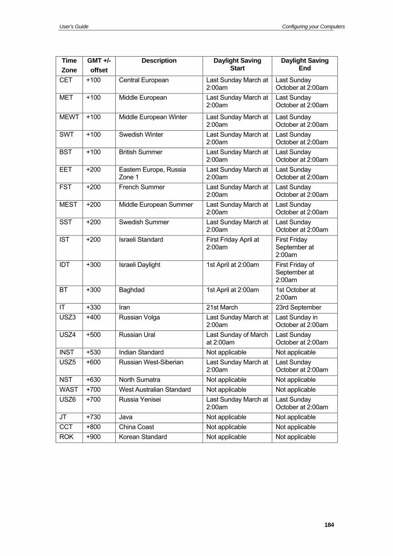
User’s Guide Configuring your Computers
Time
Zone
GMT +/-
offset
Description Daylight Saving Start
Daylight Saving End
CET +100 Central European Last Sunday March at am 2:00am
Last Sunday October at 2:00
MET
+100 Middle European Last Sunday March at am 2:00am
Last Sunday October at 2:00
MEWT +100 Middle European Winter y March at Last Sunda2:00am
Last Sunday October at 2:00am
SWT +100 Swedish Winter y March at Last Sunda2:00am
Last Sunday October at 2:00am
BST +100 British Summer y March at Last Sunda2:00am
Last Sunday October at 2:00am
EET +200 Eastern Europe, Russia y March at Zone 1
Last Sunda2:00am
Last Sunday October at 2:00am
FST +200 French Summer y March at Last Sunda2:00am
Last Sunday October at 2:00am
MEST +200 Middle European Summer y March at Last Sunda2:00am
Last Sunday October at 2:00am
SST +200 Swedish Summer y March at Last Sunda2:00am
Last Sunday October at 2:00am
IST +200 Israeli Standard April at First Friday2:00am
First Friday September at 2:00am
IDT +300 Israeli Daylight 1st April at 2:00am First Friday of September at 2:00am
BT +300 Baghdad 1st April at 2:00am 1st October a2:00am
t
IT +330 Iran 21st March 23rd September
USZ3 +400 Russian Volga Last Sunday March at 2:00am
Last Sunday in am October at 2:00
USZ4 +500 Russian Ural Last Sunday of March at 2:00am
Last Sunday October at 2:00am
INST +530 Indian Standard Not applicable Not applicable
USZ5 +600 Russian West-Siberian Last Sunday March at 2:00am
Last Sunday October at 2:00am
NST +630 North Sumatra Not applicable Not applicable
WAST +700 West Australian Standard Not applicable Not applicable
USZ6 +700 Russia Yenisei Last Sunday March at 2:00am
Last Sunday October at 2:00am
JT +730 Java Not applicable Not applicable
CCT +800 China Coast Not applicable Not applicable
ROK +900 Korean Standard Not applicable Not applicable
184
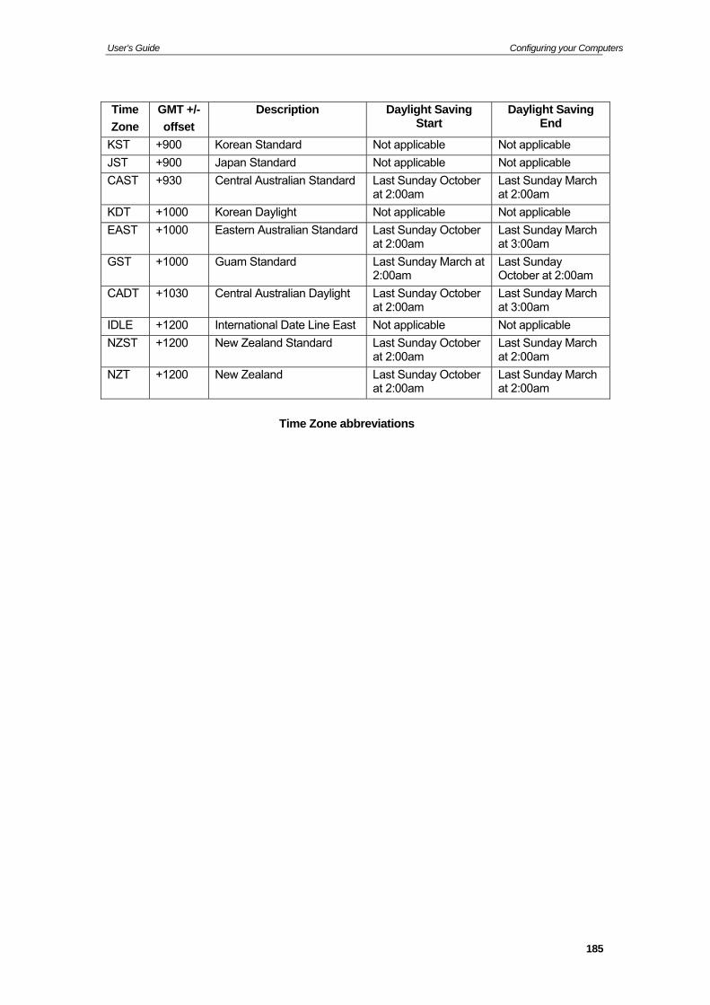
User’s Guide Configuring your Computers
Time
Zone
GMT +/-
offset
Description Daylight Saving Start
Daylight Saving End
KST +900 Korean Standard Not applicable Not applicable
JST +900 Japan Standard cable Not appli Not applicable
CAST ndard
+930 Central Australian Sta Last Sunday October at 2:00am
Last Sunday March at 2:00am
KDT +1000 Korean Daylight Not applicable Not applicable
EAST +1000 Eastern Australian Standard day October Last Sunat 2:00am
Last Sunday March at 3:00am
GST +1000 Guam Standard day March at am
Last Sun2:00am
Last Sunday October at 2:00
CADT +1030 Central Australian Daylight day October Last Sunat 2:00am
Last Sunday March at 3:00am
IDLE +1200 l Date Line East cable Internationa Not appli Not applicable
NZST ndard
+1200 New Zealand Sta Last Sunday October at 2:00am
Last Sunday March at 2:00am
NZT +1200
New Zealand Last Sunday October at 2:00am
Last Sunday March at 2:00am
Time
Zone abbre
viations
185
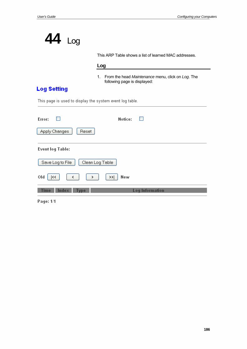
User’s Guide Configuring your Computers
44 g
ARP Table sh rned MA
Lo
This ows a list of lea C addresses.
Log
1. From the hefollowing pag
ad licke
Maintenance menu, c is displayed:
on Log. The
186
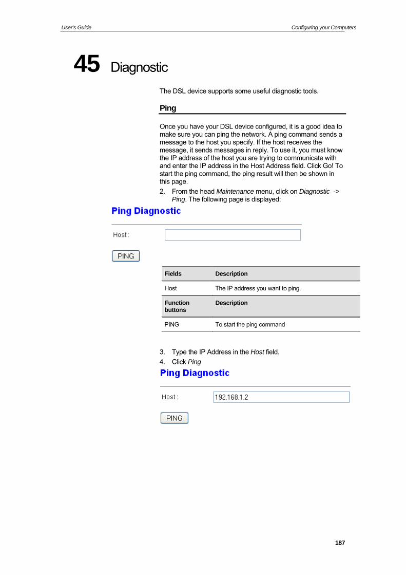
User’s Guide Configuring your Computers
45 Diagnostic
The DSL device supports some useful diagnostic tools.
Ping
Once you have your DSL device configured, it is a good ideamake sure you can ping the netw
to ork. A ping command sends a
message to the host you specify. If the host receives the message, it sends messages in reply. To use it, you must know the IP address of the host you are trying to communicate with and enter the IP address in the Host Address field. Click Go! To start the ping command, the ping result will then be shown in this page.
2. From the head Maintenance menu, click on Diagnostic -> Ping. The following page is displayed:
. Type the IP Address in the Host field.
. Click Ping
Fields Description
Host The IP address you want to ping.
Function Description buttons
PING To start the ping command
3
4
187
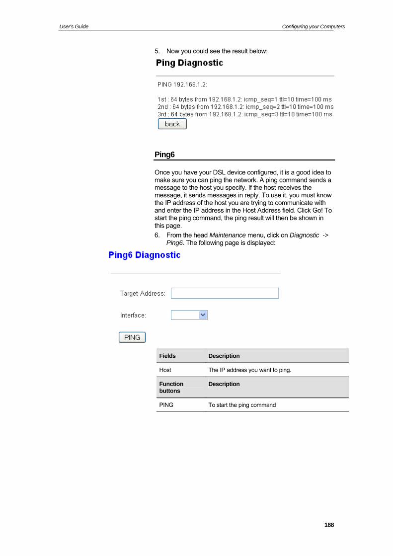
User’s Guide Configuring your Computers
5. Now you could see the result below:
Ping6
Once you have your DSL device configured, it is a good idea tmake sure
o
e it, you must know the IP address of the host you are trying to communicate with and enter the IP address in the Host Address field. Click Go! To start the ping command, the ping result will then be shown in this page.
6. From the head Maintenance menu, click on Diagnostic -> Ping6. The following page is displayed:
you can ping the network. A ping command sends a message to the host you specify. If the host receives the message, it sends messages in reply. To us
Fields Description
Host The IP address you want to ping.
Function Description buttons
PING To start the ping command
188
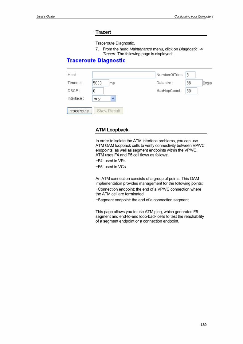
User’s Guide Configuring your Computers
Tracert
Traceroute Diagnostic.
7. From the head Maintenance menu, click on Diagnostic -> Tracert. The following page is displayed:
ATM Loopback
In order to isolate the ATM interface problems, you can use
in the VP/VC. ATM uses F4 and F5 cell flows as follows:
−F4: used in VPs
−F5: used in VCs
An ATM connection consists of a group of points. This OAM implementation provides management for the following points:
−Connection endpoint: the end of a VP/VC connection where the ATM cell are terminated
−Segment endpoint: the end of a connection segment
This page allows you to use ATM ping, which enerates F5 segment and end-to-end loop-back cells to test the reachability o ent endp ection endpoint.
ATM OAM loopback cells to verify connectivity between VP/VC endpoints, as well as segment endpoints with
g
f a segm oint or a conn
189

User’s Guide Configuring your Computers
1. From OAM Lo
the head Maintenance menu, click on Diagnostic -> opback. The following page is displayed:
190

User’s Guide Configuring your Computers
ADSL Diagnostic
This page displays the ADSL Tone Diagnostic performance. Click Start button to start the ADSL diagnostic.
1. From the head Maintenance menu, click on Diagnostic -> ADSL Diagnostic. The following page is displayed:
2. Click Start button to start the ADSL diagnostic.
191
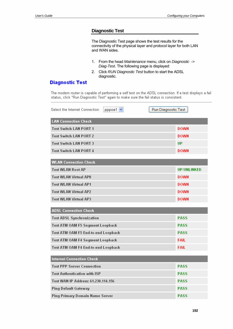
User’s Guide Configuring your Computers
Diagnostic Test
The Diagnostic Test page shows the test results for the connectivity of the physical layer and protocol layer for both LAand WAN sides.
N
SL diagnostic.
1. From the head Maintenance menu, click on Diagnostic -> Diag-Test. The following page is displayed:
2. Click RUN Diagnostic Test button to start the AD
192

User’s Guide Configuring your Computers
Fields Description
Select the Internet
The available WAN side interfaces are listed. You
Connection have to select one for the WAN side diagnostic.
Function buttons
Description
RUN Diagnostic Test
To start the RUN Diagnostic Test
193
User’s Guide Configuring your Computers
A Configuring your Computers T dix provs ur computers to work with the Wireless ADSL2+ Router.
ing Ethernet PCs
his appenettings on yo
ides instructions for configuring the Internet
Configur
Before you begin
y default, the Wireless ADSL2+ Router automatically assigns e required Internet settings to your PCs. You need to
onfigure the PCs to accept this information when it is assigned.
Bthc
In some cases, you may want to assign Internet information manually to some or all of your computers rather than allow the
Note
Wireless ADSL2+ Router to do so. See Assigning static Internet i formation to your PCs for instructions.
If you have connected your LAN PCs via Ethernet to the
Wireless ADSL2+ Router, follow the instructions that correspond to the operating system installed on your PC:
Windows® XP PCs
Windows 2000 PCs
Windows Me PCs
Windows 95, 98 PCs
Windows NT 4.0 workstations
indows® XP PCs
. In the Windows task bar, click the Start button, and then click Control Panel.
2. Double-click the Network Connections icon.
3. In the LAN or High-Speed Internet window, right-click on the icon corresponding to your network interface card (NIC) and select Properties. (Often, this icon is labeled Local Area Connection).
The Local Area Connection dialog box is displayed with a list of currently installed network items.
. Ensure that the check box to the left of the item labeled Internet Protocol TCP/IP is checked and click Properties.
. In the Internet Protocol (TCP/IP) Properties dialog box, click the radio button labeled Obtain an IP address automatically. Also click the radio button labeled Obtain DNS server address automatically.
. Click OK twice to confirm your changes, and then close the Control Panel.
indows 2000 PCs
irst, check for the IP protocol and, if necessary, install it:
1. In the Windows task bar, click the Start button, point to Settings, and then click Control Panel.
2. Double-click the Network and Dial-up Connections icon.
n
W
1
4
5
6
W
F
194
User’s Guide Configuring your Computers
3. In the Network and Dial-up Connections window, right-click the Local Area Connection icon, and then select Properties.
log box is etwork
does not display as an installed
5. In the Select Network Component Type dialog box, select en click Add…
2000 installation CD or other media. Follow the instructions
Next, configure the PCs to accept IP information assigned by the Wireless ADSL2+ Router:
p Connections window, right-click icon, and then select Properties.
Properties dialog box, select P), and then click Properties.
P/IP) Properties dialog box, click address automatically.
Also click the radio button labeled Obtain DNS server cally.
The Local Area Connection Properties diadisplayed with a list of currently installed ncomponents. If the list includes Internet Protocol (TCP/IP), then the protocol has already been enabled. Skip to step 10.
4. If Internet Protocol (TCP/IP) component, click Install…
Protocol, and th
6. Select Internet Protocol (TCP/IP) in the Network Protocols list, and then click OK.
You may be prompted to install files from your Windows
to install the files.
7. If prompted, click OK to restart your computer with the new settings.
8. In the Control Panel, double-click the Network and Dial-up Connections icon.
9. In the Network and Dial-uthe Local Area Connection
10. In the Local Area ConnectionInternet Protocol (TCP/I
11. In the Internet Protocol (TCthe radio button labeled Obtain an IP
address automati
12. Click OK twice to confirm and save your changes, and thenclose the Control Panel.
195
User’s Guide Configuring your Computers
Windows Me PCs
1. In the Windows task bar, click the Start button, point to Settings, and then click Control Panel.
Double-click the Network and Dial-up Connections icon.
In the Network and Dial-up Connections window, right-clickthe N
2.
3. etwork icon, and then select Properties.
5. t
6.
e
s dialog box, select TCP/IP, and
log box, click the radio button beled Server assigned IP address. Also click the radio
button labeled Server assigned name server address.
13. Click OK twice to confirm and save your changes, and then close the Control Panel.
Windows 95, 98 PCs
First, check for the IP protocol and, if necessary, install it:
1. In the Windows task bar, click the Start button, point to Settings, and then click Control Panel.
2. Double-click the Network icon.
The Network dialog box displays with a list of currently installed network components. If the list includes TCP/IP, and then the protocol has already been enabled. Skip to step 9.
3. If TCP/IP does not display as an installed component, click Add…
The Select Network Component Type dialog box displays.
4. Select Protocol, and then click Add…
The Select Network Protocol dialog box displays.
The Network Properties dialog box displays with a list of currently installed network components. If the list includes Internet Protocol (TCP/IP), then the protocol has already been enabled. Skip to step 11.
4. If Internet Protocol (TCP/IP) does not display as an installedcomponent, click Add…
In the Select Network Component Type dialog box, selecProtocol, and then click Add…
Select Microsoft in the Manufacturers box.
7. Select Internet Protocol (TCP/IP) in the Network Protocols list, and then click OK.
You may be prompted to install files from your Windows Minstallation CD or other media. Follow the instructions to install the files.
8. If prompted, click OK to restart your computer with the new settings.
Next, configure the PCs to accept IP information assigned by Wireless ADSL2+ Router: the
9. In the Control Panel, double-click the Network and Dial-up Connections icon.
10. In Network and Dial-up Connections window, right-click the Network icon, and then select Properties.
11. In the Network Propertiethen click Properties.
12. In the TCP/IP Settings diala
196
User’s Guide Configuring your Computers
5. Click on Microsoft in the Manufacturers list box, and then
7.
Nex information assigned by
dow, and then click the Network
abeled TCP/IP, and then
twork card or adapter.
10.
11. utton labeled Obtain an IP address
Configuration tab, and then click the radio
nd save your changes.
to
con.
s a list of currently installed network protocols. If the list includes TCP/IP, then the
y been enabled. Skip to step 9.
click
x, select TCP/IP,
NT
files are installed, a window displays to inform you
6.
ned by the
click TCP/IP in the Network Protocols list box.
6. Click OK to return to the Network dialog box, and then clickOK again.
You may be prompted to install files from your Windows 95/98 installation CD. Follow the instructions to install the files.
Click OK to restart the PC and complete the TCP/IP installation.
t, configure the PCs to accept IPthe Wireless ADSL2+ Router:
8. Open the Control Panel winicon.
9. Select the network component lclick Properties.
If you have multiple TCP/IP listings, select the listing associated with your ne
In the TCP/IP Properties dialog box, click the IP Address tab.
Click the radio bautomatically.
12. Click the DNSbutton labeled Obtain an IP address automatically.
13. Click OK twice to confirm a
You will be prompted to restart Windows.
14. Click Yes.
Windows NT 4.0 workstations
First, check for the IP protocol and, if necessary, install it:
1. In the Windows NT task bar, click the Start button, point Settings, and then click Control Panel.
2. In the Control Panel window, double click the Network i
3. In the Network dialog box, click the Protocols tab.
The Protocols tab display
protocol has alread
4. If TCP/IP does not display as an installed component,Add…
5. In the Select Network Protocol dialog boand then click OK.
You may be prompted to install files from your Windowsinstallation CD or other media. Follow the instructions to install the files.
After all that a TCP/IP service called DHCP can be set up to dynamically assign IP information.
Click Yes to continue, and then click OK if prompted to restart your computer.
Next, configure the PCs to accept IP information assigWireless ADSL2+ Router:
197
User’s Guide Configuring your Computers
7. Open the Control Panel window, and then double-click theNetwork icon.
cols tab, select TCP/IP, and then click
10. button labeled Obtain an IP address from a DHCP
to confirm and save your changes, and then
In sinfo“static 2+ Router to
that s (for
are
Bef information
sk of each PC
gateway for your LAN. In ort on
m (DNS)
On follo r
ns for displaying each of the Internet Protocol
computer, DNS server and default gateinfo
8. In the Network dialog box, click the Protocols tab.
9. In the ProtoProperties.
In the Microsoft TCP/IP Properties dialog box, click the radio server.
11. Click OK twiceclose the Control Panel.
sAs igning static Internet information to your PCs
If you are a typical user, you will not need to assign static Internet information to your LAN PCs because your ISP automatically assigns this information for you.
ome cases however, you may want to assign Internet rmation to some or all of your PCs directly (often called
ally”), rather than allowing the Wireless ADSLassign it. This option may be desirable (but not required) if:
You have obtained one or more public IP addressesyou want to always associate with specific computerexample, if you are using a computer as a public web server).
You maintain different subnets on your LAN (subnets described in Appendix B).
ore you begin, you must have the following available:
The IP address and subnet ma
The IP address of the defaultmost cases, this is the address assigned to the LAN pthe Wireless ADSL2+ Router. By default, the LAN port is assigned the IP address 192.168.1.1. (You can change thisnumber or another number can be assigned by your ISP. See Addressing for more information.)
The IP address of your ISP’s Domain Name Systeserver.
each PC to which you want to assign static information,w the instructions relating only to checking for and/o
installing the IP protocol. Once it is installed, continue to follow the instructio(TCP/IP) properties. Instead of enabling dynamic assignment of the IP addresses for the
way, click the radio buttons that enable you to enter the rmation manually.
Your IP addresses that place them in the same PCs must havesubn lly et as the Wireless ADSL2+ Router’s LAN port. If you manua
Note
assign IP information to all your LAN PCs, you can follow the instr LAN port IP address uctions in Addressing to change theaccordingly.
198
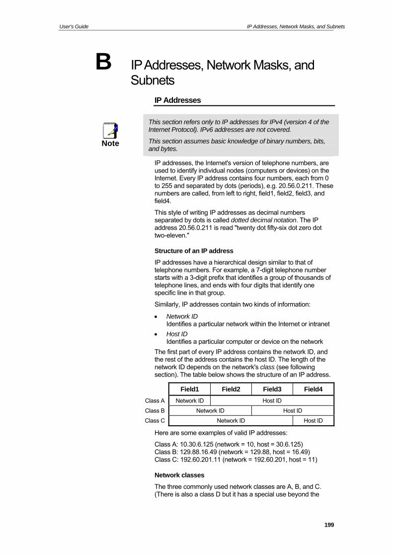
User’s Guide IP Addresses, Network Masks, and Subnets
B IP Addresses, Network Masks, and Subnets
IP Addresses
This section refers only to IP addresses for IPv4 (version 4 of the Internet Protocol). IPv6 addresses are not covered.
Note T s, his section assumes basic knowledge of binary numbers, bit
an
s, are vices) on the
m 0
er 3-digit prefix that identifies a group of thousands of
fy one
of every IP address contains the network ID, and e
d bytes.
IP addresses, the Internet's version of telephone numberused to identify individual nodes (computers or deInternet. Every IP address contains four numbers, each froto 255 and separated by dots (periods), e.g. 20.56.0.211. Thesenumbers are called, from left to right, field1, field2, field3, and field4.
This style of writing IP addresses as decimal numbers separated by dots is called dotted decimal notation. The IP address 20.56.0.211 is read "twenty dot fifty-six dot zero dot two-eleven."
Structure of an IP address
IP addresses have a hierarchical design similar to that of telephone numbers. For example, a 7-digit telephone numbstarts with atelephone lines, and ends with four digits that identispecific line in that group.
Similarly, IP addresses contain two kinds of information:
Network ID Identifies a particular network within the Internet or intranet
Host ID Identifies a particular computer or device on the network
The first partthe rest of the address contains the host ID. The length of thnetwork ID depends on the network's class (see following section). The table below shows the structure of an IP address.
Field1 Field2 Field3 Field4
Class A Network ID Host ID
Class B Network ID Host ID
Class C Network ID Host ID
Here are some examples of valid IP addresses:
Class A: 10.30.6.125 (network = 10, host = 30.6.125) Class B: 129.88.16.49 (network = 129.88, host = 16.49) Class C: 192.60.201.11 (network = 192.60.201, host = 11)
twork classes
The three commonly used network classes are A, B, and C. (There is also a class D but it has a special use beyond the
Ne
199
User’s Guide IP Addresses, Network Masks, and Subnets
scope of this discussion.) These classes have different uses
with ver 16 million hosts. Up to 126 of these huge
can exist, for a total of over 2 billion hosts. Because of their huge size, these networks are used for WANs and by
e infrastructure level of the Internet, such as your ISP.
ppropriate
lues not shown are reserved for special uses)
alue except all fields set to 0 or all ial
and characteristics.
Class A networks are the Internet's largest networks, each room for onetworks
organizations at th
Class B networks are smaller but still quite large, each able to hold over 65,000 hosts. There can be up to 16,384 class B networks in existence. A class B network might be afor a large organization such as a business or government agency.
Class C networks are the smallest, only able to hold 254 hosts at most, but the total possible number of class C networks exceeds 2 million (2,097,152 to be exact). LANs connected to the Internet are usually class C networks.
Some important notes regarding IP addresses:
The class can be determined easily from field1: field1 = 1-126: Class A field1 = 128-191: Class B field1 = 192-223: Class C (field1 va
A host ID can have any vfields set to 255, as those values are reserved for specuses.
Subnet masks
A rn of mask looks like a regular IP address, but contains a pattebit and s that tells what parts of an IP address are the network ID
Definitionmask
what parts are the host ID: bits set to 1 mean "this bit is part of the network ID" and bits set to 0 mean "this bit is part of the host ID."
Subnet masks are used to define subnets (what you get after ding a network into smaller pieces). A subnet's network ID divi is
created by "borrowing" one or more bits from the host ID portion of the address. The subnet mask identifies these host ID bits.
For example, consider a class C network 192.168.1. To split thisinto two subnets, you would use the subnet mask:
55.255.
as hat's happening if w is in binary:
1111. 111 00000
1 through mask
e this wo
ual C address).
k
2 255.128
It's e ier to see w e write th
1111 11111. 11111111.100
As with any class C address, all of the bits in fieldfield3 are part of the network ID, but note how thespecifies that the first bit in field4 is also included. Sincextra bit has only two values (0 and 1), this means there are tsubnets. Each subnet uses the remaining 7 bits in field4 for itshost IDs, which range from 1 to 126 hosts (instead of the us0 to 255 for a class
Similarly, to split a class C network into four subnets, the masis:
200
User’s Guide IP Addresses, Network Masks, and Subnets
255.255.255.192 or 11111111. 11111111. 11111111.11000000
The two extra bits in field4 can have four values (00, 01, 10, 11),so there are four subnets. Each subnet uses the remaininbits in field4 for its host IDs, ranging from 1 to 62.
g six
S subnet mask does not specify any additional ometimes anetwork ID bits, and thus no subnets. Such a mask is called a default subnet mask. These masks are:
Class A: 255.0.0.0
Note Class B: 255.255.0.0 Cl 255.255.255.0 ass C:
T hese are called default because they are used when a network isin
itially configured, at which time it has no subnets.
201
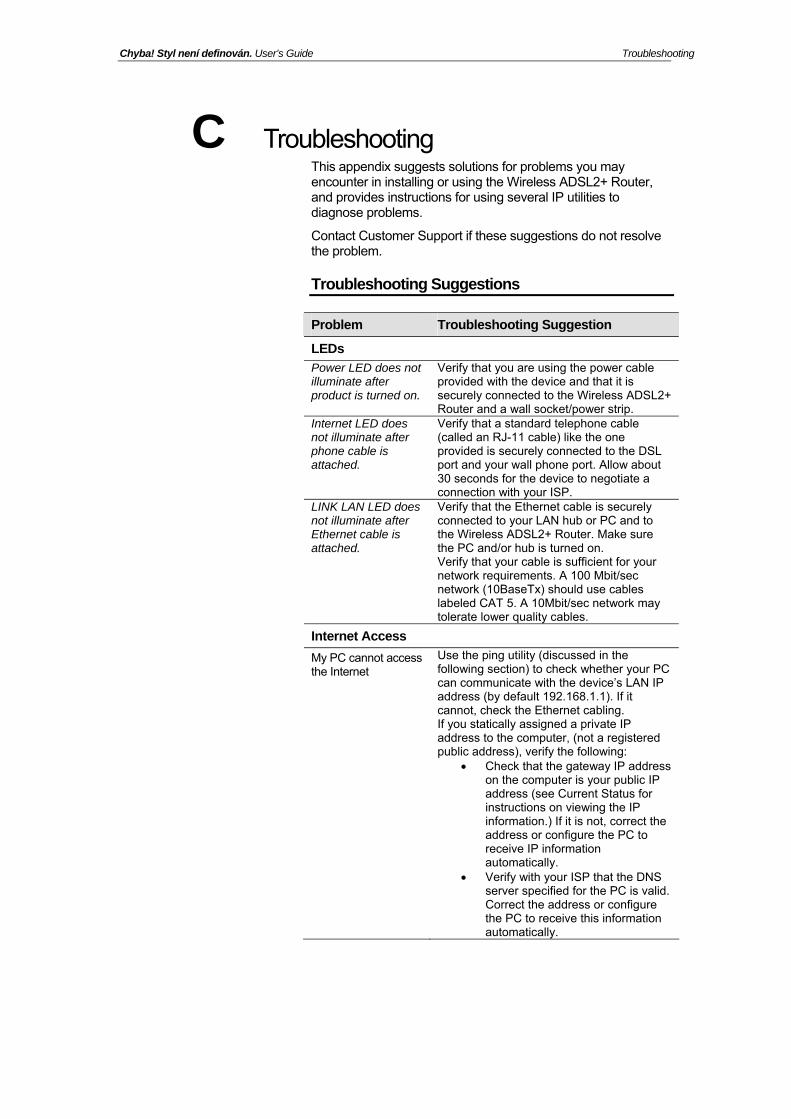
Chyba! Styl není definován. User’s Guide Troubleshooting
C Trou
Router, and provides instructions for using several IP utilities to
e
lesh gestions
bleshooting This appendix suggests solutions for problems you may encounter in installing or using the Wireless ADSL2+
diagnose problems.
Contact Customer Support if these suggestions do not resolvthe problem.
Troub ooting Sug
Problem Troubleshooting Suggestion
LEDs
Power LED does not illuminate after product is turned on.
Verify that you are using the power cable provided with the device and that it is securely connected to the Wireless ADSL2+ Router and a wall socket/power strip.
Internet LED does not illuminate after phone cable is attached.
Verify that a standard telephone cable (called an RJ-11 cable) like the one provided is securely connected to the DSL port and your wall phone port. Allow about 30 seconds for the device to negotiate a connection with your ISP.
LINK LAN LED does not illuminate after Ethernet cable is attached.
Verify that the Ethernet cable is securely connected to your LAN hub or PC and to the Wireless ADSL2+ Router. Make sure the PC and/or hub is turned on. Verify that your cable is sufficient for your network requirements. A 100 Mbit/sec network (10BaseTx) should use cables labeled CAT 5. A 10Mbit/sec network may tolerate lower quality cables.
Internet Access
My PC cannot access the Internet
Use the ping utility (discussed in the following section) to check whether your PC can communicate with the device’s LAN IP address (by default 192.168.1.1). If it cannot, check the Ethernet cabling. If you statically assigned a private IP address to the computer, (not a registered public address), verify the following:
Check that the gateway IP address on the computer is your public IP address (see Current Status for instructions on viewing the IP information.) If it is not, correct the address or configure the PC to receive IP information automatically.
Verify with your ISP that the DNS server specified for the PC is valid. Correct the address or configure the PC to receive this information automatically.
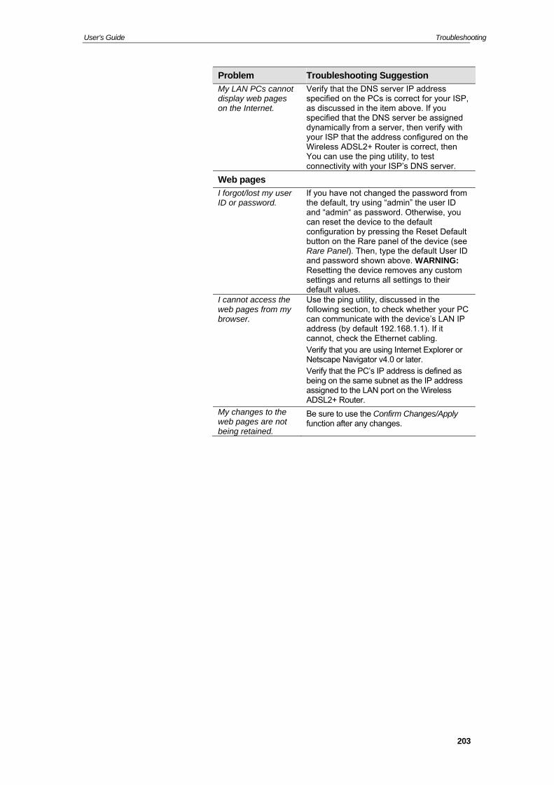
User’s Guide Troubleshooting
Problem Troubleshooting Suggestion
My LAN PCs cannot display web pages on the Internet.
Vsa
erify that the DNS server IP address pecified on the PCs is correct for your ISP, s discussed in the item above. If you
gned
on the
You can use the ping utility, to test
specified that the DNS server be assidynamically from a server, then verify withyour ISP that the address configuredWireless ADSL2+ Router is correct, then
connectivity with your ISP’s DNS server.
Web pages
I forgot/lost my user ID or password.
If you have not chthe default, try us
anged the password from ing “admin” the user ID
and “admin“ as password. Otherwise, you
t Default button on the Rare panel of the device (see
can reset the device to the default configuration by pressing the Rese
Rare Panel). Then, type the default User ID and password shown above. WARNING: Resetting the device removes any custom settings and returns all settings to their default values.
I cannot access theweb pages from mybrowser.
Use the ping utility, discussed in the following section, to check whether your PCcan communicate with the device’s LAN IP address (by default 192.168.1.1). If it cannot, check the Ethernet cabling. Verify that you are using Internet Explorer orNetscape Navigator v4.0 or later. Verify that the PC’s IP address is defined asbeing on the same subnet as the IP address assigned to the LAN port on the Wireless ADSL2+ Router.
My changes to the web pages are not being retained.
Be sure to use the Confirm Changes/Applyfunction after any changes.
203
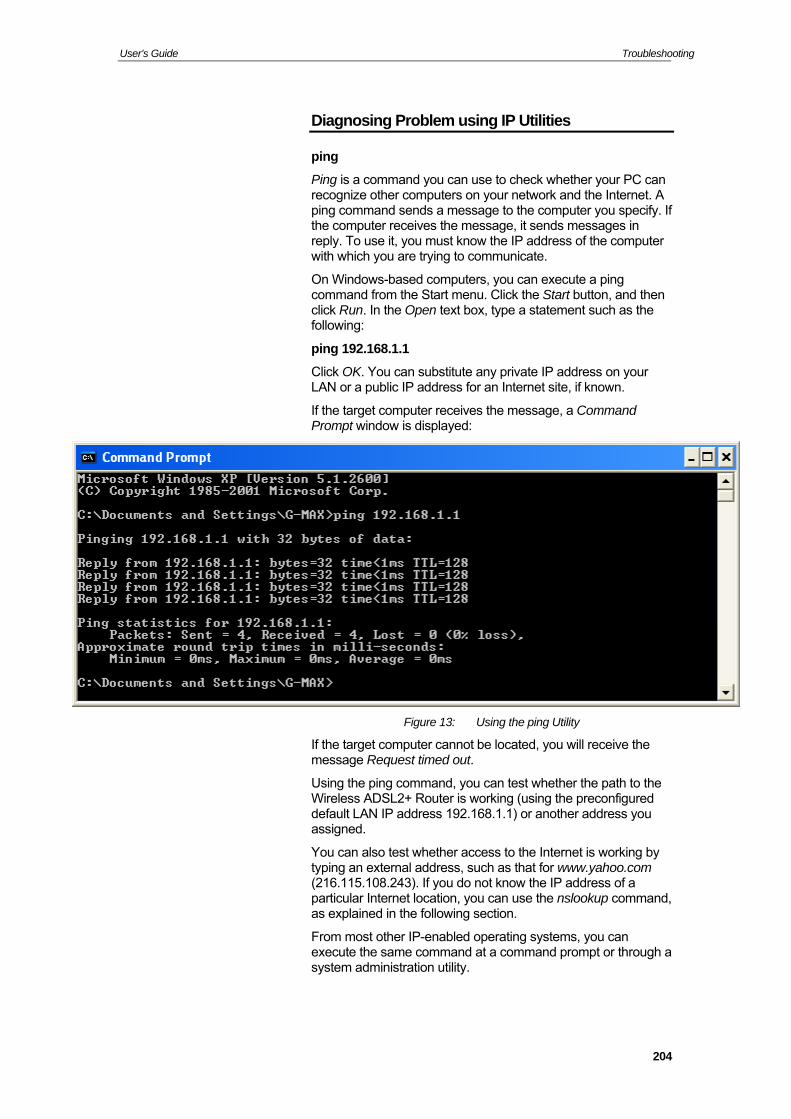
User’s Guide Troubleshooting
Diagnosing Problem using IP Utilities
ping
Ping is a command yo recognize other compping command sends If the computer receivesreply. To use it, you m r
u are trying to communicate.
che St
click Run. In the Openfollowing:
ping 192.168.1.1
Click OK. You can subLAN or a public IP add
If the target computer ssage, a Command isp
u can use to check whether your PC canuters on your network and the Internet. A a message to the computer you specify. the message, it sends messages in ust know the IP address of the compute
with which yo
On Windows-basedcommand from t
omputers, you can execute a ping art menu. Click the Start button, and then text box, type a statement such as the
stitute any private IP address on your ress for an Internet site, if known.
receives the mePrompt window is d layed:
Figure 13: Using the ping Utility
If the target computer cannot be located, you will receive the message Request timed out.
Using the ping command, you can test whether the path to the Wireless ADSL2+ Router is working (using the preconfigured default LAN IP address 192.168.1.1) or another address you assigned.
You can also test whether access to the Internet is working by typing an external address, such as that for www.yahoo.com (216.115.108.243). If you do not know the IP address of a particular Internet location, you can use the nslookup command, as explained in the following section.
From most other IP-enabled operating systems, you can execute the same command at a command prompt or through a system administration utility.
204
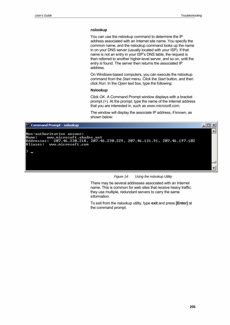
User’s Guide Troubleshooting
nslookup
ne the IP address associated with an Internet site name. You specify the
on name, and the nslookup command looks up the name
cute the nslookup d then
mmand Prompt window displays with a bracket rompt, type the name of the Internet address
, as
You can use the nslookup command to determi
commin on your DNS server (usually located with your ISP). If that name is not an entry in your ISP’s DNS table, the request is then referred to another higher-level server, and so on, until the entry is found. The server then returns the associated IP address.
On Windows-based computers, you can execommand from the Start menu. Click the Start button, anclick Run. In the Open text box, type the following:
Nslookup
Click OK. A Coprompt (>). At the pthat you are interested in, such as www.microsoft.com.
The window will display the associate IP address, if knownshown below:
Figure 14: Using the nslookup Utility
There may be several addresses associated with an Internet name. This is common for web sites that receive heavy traffic; they use multiple, redundant servers to carry the same information.
To exit from the nslookup utility, type exit and press [Enter] at the com
mand prompt.
205
User’s Guide Glossary
206
D Glos10BASE-T
100BASE-T a data rate of 100 Mbps. Also known as
ADSL me users
rical DSL. The term asymmetrical refers to its
analog nal is a signal that has had its frequency modified in some way, such as by amplifying its strength or varying its frequency, in order to add information to the signal. The voice component in DSL is an analog signal. See digital.
ATM Asynchronous Transfer Mode A standard for high-speed transmission of data, text, voice, and video, widely used within the Internet. ATM data rates range from 45 Mbps to 2.5 Gbps. See data rate.
authenticate To verify a user’s identity, such as by prompting for a password.
binary The "ba y two digits,
IP .191.4.240 is
bit Short for "binary digit," a bit is a number that can have two values, 0 or 1. See binary.
bps bits per second
bridging Passing data from your network to your ISP and vice versa using the hardware addresses of the devices at each location. Bridging contrasts with routing, which can add more intelligence to data transfers by using network addresses instead. The Wireless ADSL2+ Router can perform both routing and bridging. Typically, when both functions are enabled, the device routes IP data and bridges all other types of data. See routing.
broadband A telecommunications technology that can send different types of data over the same medium. DSL is a broadband technology.
broadcast To send data to all computers on a network.
sary A designation for the type of wiring used by Ethernet networks with a data rate of 10 Mbps. Also known as Category 3 (CAT 3) wiring. See data rate, Ethernet.
A designation for the type of wiring used by Ethernet networks withCategory 5 (CAT 5) wiring. See data rate, Ethernet.
Asymmetric Digital Subscriber Line The most commonly deployed "flavor" of DSL for hois asymmetunequal data rates for downloading and uploading (the download rate is higher than the upload rate). The asymmetrical rates benefit home users because they typically download much more data from the Internet than they upload.
An analog sig
se two" system of numbers, that uses onl0 and 1, to represent all numbers. In binary, the number 1 is written as 1, 2 as 10, 3 as 11, 4 as 100, etc. Although expressed as decimal numbers for convenience, IP addresses in actual use are binary numbers; e.g., theaddress 20911010001.10111111.00000100.11110000 in binary. See bit,IP address, network mask.
User’s Guide Glossary
DHCP Dynamic Host Configuration Protocol DHCP automates address assignment and management.
omputer connects to the LAN, DHCP assigns it an s from a shared pool of IP addresses; after a
ool.
e DHCP P
erver
digital ssed L
nal. See analog.
hoo.com is the domain name associated with IP n you start to access a web
name.
IP address. Domain names must be unique; their
download
DSL
FTP
ng b server, and downloading files
Gbps net data rates are often expressed in Gbps.
network.
When a cIP addresspecified time limit, DHCP returns the address to the p
DHCP relay Dynamic Host Configuration Protocol relay A DHCP relay is a computer that forwards DHCP databetween computers that request IP addresses and thserver that assigns the addresses. Each of the WirelessADSL2+ Router's interfaces can be configured as a DHCrelay. See DHCP.
DHCP s Dynamic Host Configuration Protocol server A DHCP server is a computer that is responsible for assigning IP addresses to the computers on a LAN. See DHCP.
Of data, having a form based on discrete values expreas binary numbers (0's and 1's). The data component in DSis a digital sig
DNS Domain Name System The DNS maps domain names into IP addresses. DNS information is distributed hierarchically throughout the Internet among computers called DNS servers. For example, www.yaaddress 216.115.108.243. Whesite, a DNS server looks up the requested domain name to find its corresponding IP address. If the DNS server cannot find the IP address, it communicates with higher-level DNS servers to determine the IP address. See domain
domain name A domain name is a user-friendly name used in place of its associated assignment is controlled by the Internet Corporation for Assigned Names and Numbers (ICANN). Domain names area key element of URLs, which identify a specific file at a web site. See DNS.
To transfer data in the downstream direction, i.e., from theInternet to the user.
Digital Subscriber Line A technology that allows both digital data and analog voice signals to travel over existing copper telephone lines.
encryption keys See network keys
Ethernet The most commonly installed computer network technology, usually using twisted pair wiring. Ethernet data rates are 10 Mbps and 100 Mbps. See also 10BASE-T, 100BASE-T, twisted pair.
File Transfer Protocol A program used to transfer files between computers connected to the Internet. Common uses include uploadinew or updated files to a wefrom a web server.
Abbreviation of Gigabits per second, or one billion bits per second. Inter
host A device (usually a computer) connected to a
207

User’s Guide Glossary
HTTP Hyper-Text Transfer Protocol HTTP is the main protocol used to transfer data from web sites so that it can be displayed by web browsers. See web browser, web site.
A hub is a place of convergence where data arrives from onHub e e or more
oup
ICMP l used to report errors and other network-
s use of ICMP.
IEEE t of
s that often become national and international
Internet unications.
et f the but
IP
IP address
nd
ISP Provider
e
MAC address nt hardware address of a device, assigned by
addresses are expressed as six pairs . For
mask
Mbps abits per second, or one million bits per
NAT ur
network’s publicly known IP address into a private IP address for each computer on your LAN. Only your Router and your
or more directions and is forwarded out in ondirections. It connects an Ethernet bridge/Router to a grof PCs on a LAN and allows communication to pass between the networked devices.
Internet Control Message Protocol An Internet protocorelated information. The ping command make
The Institute of Electrical and Electronics Engineers is a technical professional society that fosters the developmenstandardstandards.
The global collection of interconnected networks used for both private and business comm
intran A private, company-internal network that looks like part oInternet (users access information using web browsers), is accessible only by employees.
See TCP/IP.
Internet Protocol address The address of a host (computer) on the Internet, consistingof four numbers, each from 0 to 255, separated by periods, e.g., 209.191.4.240. An IP address consists of a network ID that identifies the particular network the host belongs to, aa host ID uniquely identifying the host itself on that network. A network mask is used to define the network ID and the host ID. Because IP addresses are difficult to remember,they usually have an associated domain name that can be specified instead. See domain name, network mask.
Internet ServiceA company that provides Internet access to its customers, usually for a fee.
LAN Local Area Network A network limited to a small geographic area, such as a home or small office.
LED Light Emitting DiodAn electronic light-emitting device. The indicator lights on the front of the Wireless ADSL2+ Router are LEDs.
Media Access Control address The permaneits manufacturer. MAC of hex characters, with each pair separated by colonsexample; NN:NN:NN:NN:NN:NN.
See network mask.
Abbreviation for Megsecond. Network data rates are often expressed in Mbps.
Network Address Translation A service performed by many Routers that translates yo
208

User’s Guide Glossary
LAN know these addresses; thpublic IP address when talking to a computer on your LAN.
A group of computers that are connected together, allowing them to communica
e outside world sees only the
network te with each other and share resources,
network mask
t this bit" while bits set to 0 mean network mask
NIC des
interface to your network cabling. For Ethernet -
estination address).
g t (or Inter-Network) Groper hether the host associated with an
port
PPP IP
PP called PPPoA and PPPoE.
PPPoA tocol over ATM ou can define for a
E l over Ethernet
r
remote or example, an employee ogs in to the company’s intranet is a
s .
RJ-11
such as software, files, etc. A network can be small, such as a LAN, or very large, such as the Internet.
A network mask is a sequence of bits applied to an IP address to select the network ID while ignoring the host ID. Bits set to 1 mean "selec"ignore this bit." For example, if the 255.255.255.0 is applied to the IP address 100.10.50.1, the network ID is 100.10.50, and the host ID is 1. See binary, IP address, subnet.
Network Interface Card An adapter card that plugs into your computer and provithe physicalNICs this is typically an RJ-45 connector. See Ethernet, RJ45.
packet Data transmitted on a network consists of units called packets. Each packet contains a payload (the data), plus overhead information such as where it came from (source address) and where it should go (d
pin Packet InterneA program used to verify wIP address is online. It can also be used to reveal the IP address for a given domain name.
A physical access point to a device such as a computer or Router, through which data flows into and out of the device.
Point-to-Point Protocol A protocol for serial data transmission that is used to carry(and other protocol) data between your ISP and your computer. The WAN interface on the Wireless ADSL2+Router uses two forms of PSee PPPoA, PPPoE.
Point-to-Point ProOne of the two types of PPP interfaces yVirtual Circuit (VC), the other type being PPPoE. You candefine only one PPPoA interface per VC.
PPPo Point-to-Point ProtocoOne of the two types of PPP interfaces you can define for a Virtual Circuit (VC), the other type being PPPoA. You can define one or more PPPoE interfaces per VC.
protocol A set of rules governing the transmission of data. In order foa data transmission to work, both ends of the connection have to follow the rules of the protocol.
In a physically separate location. Faway on travel who lremote user.
RIP Routing Information Protocol The original TCP/IP routing protocol. There are two versionof RIP: version I and version II
Registered Jack Standard-11 The standard plug used to connect telephones, fax
209
User’s Guide Glossary
machines, modems, etc. to a telephone port. It is a 6-pin connector usually containing four wires.
RJ-45 Registered Jack Standard-45 The 8-pin plug used in transmitting data over phone lines. Ethernet cabling usually uses this type of connector.
Forwarding data between your network androuting the Internet on
SDNS
et network. The subnet is
ed as though they were on a separate network. See
subnet mask
TCP
P tocol
ile IP is responsible
Telnet TP
vides WPA with a
shed using one port,
nd them.
edded IP address of each
ct destination. You can y out address replacement, and
ly, UDP
the most efficient route, based on the data’s destination IP address and current network conditions. A device that performs routing is called a Router.
Secondary Domain Name System (server) A DNS server that can be used if the primary DSN server is not available. See DNS.
subn A subnet is a portion of adistinguished from the larger network by a subnet mask that selects some of the computers of the network and excludes all others. The subnet's computers remain physically connected to the rest of the parent network, but they are treatnetwork mask.
A mask that defines a subnet. See network mask.
See TCP/IP.
TCP/I Transmission Control Protocol/Internet ProThe basic protocols used on the Internet. TCP is responsible for dividing data up into packets for delivery and reassembling them at the destination, whfor delivering the packets from source to destination. When TCP and IP are bundled with higher-level applications such as HTTP, FTP, Telnet, etc., TCP/IP refers to this whole suiteof protocols.
An interactive, character-based program used to access a remote computer. While HTTP (the web protocol) and Fonly allow you to download files from a remote computer, Telnet allows you to log into and use a computer from a remote location.
TFTP Trivial File Transfer Protocol A protocol for file transfers, TFTP is easier to use than File Transfer Protocol (FTP) but not as capable or secure.
TKIP Temporal Key Integrity Protocol (TKIP) prodata encryption function. It ensures that a unique master key is generated for each packet, supports message integrity and sequencing rules and supports re-keying mechanisms.
triggers Triggers are used to deal with application protocols that create separate sessions. Some applications, such as NetMeeting, open secondary connections during normal operations, for example, a connection to a server is establibut data transfers are performed on a separate connection. A trigger tells the device to expect these secondary sessions ahow to handle
Once you set a trigger, the embincoming packet is replaced by the correct host address so that NAT can translate packets to the correspecify whether you want to carrif so, whether to replace addresses on TCP packets onpackets only, or both.
210
User’s Guide Glossary
twisted pair pairs twisted
and noise. Each telephone
ry n
unnumbered interface
he source and destination address IP address
d interface is temporary – PPP or DHCP will
of data transmission from the user to the
VC
VCI
WAN rk rge geographical area, such as
rowser l
s
b
Web page
hyperlink, web site.
Web site
The ordinary copper telephone wiring used by telephone companies. It contains one or more wire together to reduce inductance line uses one pair. In homes, it is most often installed with two pairs. For Ethernet LANs, a higher grade called Catego3 (CAT 3) is used for 10BASE-T networks, and an evehigher grade called Category 5 (CAT 5) is used for 100BASE-T networks. See 10BASE-T, 100BASE-T, Ethernet.
s
An unnumbered interface is an IP interface that does not have a local subnet associated with it. Instead, it uses a Router-id that serves as tof packets sent to and from the Router. Unlike theof a normal interface, the Router-id of an unnumbered interface is allowed to be the same as the IP address of another interface. For example, the WAN unnumbered interface of your device uses the same IP address of the LAN interface (192.168.1.1).
The unnumbereassign a ‘real’ IP address automatically.
upstream The direction Internet.
Virtual Circuit A connection from your DSL Router to your ISP.
Virtual Circuit Identifier Together with the Virtual Path Identifier (VPI), the VCI uniquely identifies a VC. Your ISP will tell you the VCI for each VC they provide. See VC.
VPI Virtual Path Identifier Together with the Virtual Circuit Identifier (VCI), the VPI uniquely identifies a VC. Your ISP will tell you the VPI for each VC they provide. See VC.
Wide Area NetwoAny network spread over a laa country or continent. With respect to the Wireless ADSL2+Router, WAN refers to the Internet.
Web b A software program that uses Hyper-Text Transfer Protoco(HTTP) to download information from (and upload to) web sites, and displays the information, which may consist of text,graphic images, audio, or video, to the user. Web browseruse Hyper-Text Transfer Protocol (HTTP). Popular webrowsers include Netscape Navigator and Microsoft Internet Explorer. See HTTP, web site, WWW.
A web site file typically containing text, graphics and hyperlinks (cross-references) to the other pages on that web site, as well as to pages on other web sites. When a user accesses a web site, the first page that is displayed is called the home page. See
A computer on the Internet that distributes information to (and gets information from) remote users through web browsers. A web site typically consists of web pages that contain text, graphics, and hyperlinks. See hyperlink, web page.
211

User’s Guide Glossary
WWW World Wide Web
Also called (the) Web. Collective term for all web sites anywhere in the world that can be accessed via the Internet.
212