Embed Size (px)
Citation preview
Wireless AntennaInstallation Guide
10 Tips for Making Your Wireless Installation a Success
Making Wireless EasyInternational Headquarters707 Dayton Road • PO Box 1040Ottawa, IL 61350 USAPhone: 815.433.5100 • Fax: 815.433.5109
Europe, Africa, Middle East10 Westlink Commercial ParkOranmore, Co. Galway, IrelandPhone: +353.91.792444 • Fax: +353.91.792445U.K. +44.01926.851500
Making Wireless Easy
Documentation #2417PN #8912www.advantech-bb.com
12 | Additional Resources
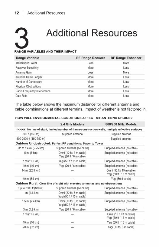
RANGE VARIABLES AND THEIR IMPACT
Range Variable RF Range Reducer RF Range EnhancerTransmitter Power Less MoreReceiver Sensitivity More LessAntenna Gain Less MoreAntenna Cable Length More LessNumber of Connectors More LessPhysical Obstructions More LessRadio Frequency Interference More LessData Rate More Less
The table below shows the maximum distance for different antenna and cable combinations at different terrains. Impact of weather is not factored in.
HOW WILL ENVIRONMENTAL CONDITIONS AFFECT MY ANTENNA CHOICE?
2.4 GHz Models 868/900 MHz ModelsIndoor: No line of sight, limited number of frame-construction walls, multiple reflective surfaces
500 ft (150 m) Supplied antenna Supplied antenna500-2600 ft (150-750 m) — Supplied antenna
Outdoor Unobstructed: Perfect RF conditions: Tower to TowerUp to 1.4 mi (2.25 km) Supplied antenna (no cable) Supplied antenna (no cable)
5 mi (8 km) Omni (10 ft / 3 m cable) Yagi (20 ft / 6 m cable)
Supplied antenna (no cable)
7 mi (11.2 km) Yagi (50 ft / 15 m cable) Supplied antenna (no cable)10 mi (16 km) Yagi (20 ft / 6 m cable) Supplied antenna (no cable)
14 mi (22.5 km) — Omni (50 ft / 15 m cable) Yagi (50 ft / 15 m cable)
40 mi (64 km) — Yagi (50 ft cable)Outdoor Rural: Clear line of sight with elevated antennas and no obstructions
Up to 2900 ft (870 m) Supplied antenna (no cable) Supplied antenna (no cable)1 mi (1.6 km) Omni (20 ft / 6 m cable)
Yagi (50 ft / 15 m cable)Supplied antenna (no cable)
1.5 mi (2.4 km) Omni (10 ft / 3 m cable) Yagi (50 ft / 15 m cable)
Supplied antenna (no cable)
3 mi (4.8 km) Yagi (20 ft / 6 m cable) Supplied antenna (no cable)7 mi (11.2 km) — Omni (10 ft / 3 m cable)
Yagi (50 ft / 15 m cable)10 mi (16 km) — Yagi (50 ft / 15 m cable)20 mi (32 km) — Yagi (10 ft / 3 m cable)
3 Additional Resources Table of Contents
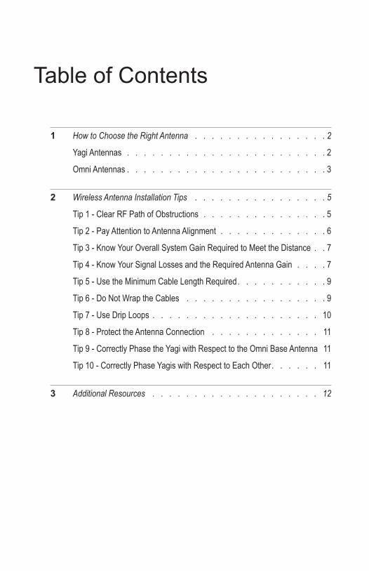
1 How to Choose the Right Antenna . . . . . . . . . . . . . . . . 2
Yagi Antennas . . . . . . . . . . . . . . . . . . . . . . . . 2
Omni Antennas . . . . . . . . . . . . . . . . . . . . . . . . 3
2 Wireless Antenna Installation Tips . . . . . . . . . . . . . . . . 5
Tip 1 - Clear RF Path of Obstructions . . . . . . . . . . . . . . . 5
Tip 2 - Pay Attention to Antenna Alignment . . . . . . . . . . . . . 6
Tip 3 - Know Your Overall System Gain Required to Meet the Distance . . 7
Tip 4 - Know Your Signal Losses and the Required Antenna Gain . . . . 7
Tip 5 - Use the Minimum Cable Length Required . . . . . . . . . . . 9
Tip 6 - Do Not Wrap the Cables . . . . . . . . . . . . . . . . . 9
Tip 7 - Use Drip Loops . . . . . . . . . . . . . . . . . . . . 10
Tip 8 - Protect the Antenna Connection . . . . . . . . . . . . . 11
Tip 9 - Correctly Phase the Yagi with Respect to the Omni Base Antenna 11
Tip 10 - Correctly Phase Yagis with Respect to Each Other . . . . . . 11
3 Additional Resources . . . . . . . . . . . . . . . . . . . . 12
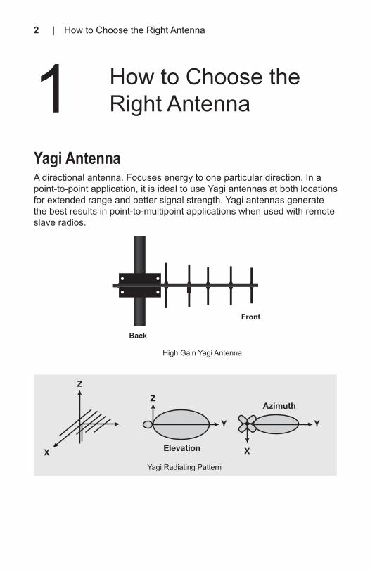
Yagi AntennaA directional antenna. Focuses energy to one particular direction. In a point-to-point application, it is ideal to use Yagi antennas at both locations for extended range and better signal strength. Yagi antennas generate the best results in point-to-multipoint applications when used with remote slave radios.
High Gain Yagi Antenna
Back
Front
Y
X
Azimuth
Y
Z
Elevation
Z
X
Yagi Radiating Pattern
1 How to Choose the Right Antenna
2 | How to Choose the Right Antenna Wireless Antenna Installation Guide | 11
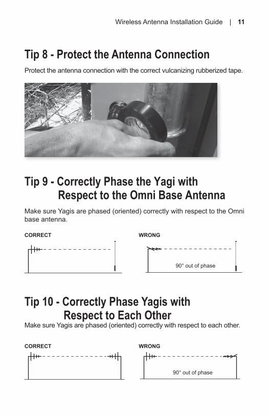
Tip 8 - Protect the Antenna Connection Protect the antenna connection with the correct vulcanizing rubberized tape.
CORRECT WRONG
CORRECT WRONG
90° out of phase
90° out of phase
Tip 10 - Correctly Phase Yagis with Respect to Each OtherMake sure Yagis are phased (oriented) correctly with respect to each other.
Tip 9 - Correctly Phase the Yagi with Respect to the Omni Base AntennaMake sure Yagis are phased (oriented) correctly with respect to the Omni base antenna.

10 | Installation Tips
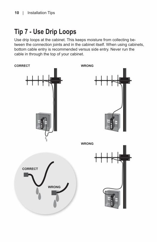
Tip 7 - Use Drip LoopsUse drip loops at the cabinet. This keeps moisture from collecting be-tween the connection joints and in the cabinet itself. When using cabinets, bottom cable entry is recommended versus side entry. Never run the cable in through the top of your cabinet.
CORRECT WRONG
WRONG
CORRECT
WRONG
Omni AntennaOmni-directional antennas focus their energy equally in all directions. They typically have lesser range than a Yagi antenna of similar gain. Omni antennas are used in point-to-multipoint applications for the central master unit.
Omni-Directional Antenna
Y
Azimuth
X
Z
Y
Elevation
Z
Y
XBase Station Radiation Pattern
Wireless Antenna Installation Guide | 3
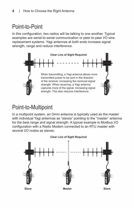
Point-to-PointIn this configuration, two radios will be talking to one another. Typical examples are serial-to-serial communication or peer-to-peer I/O wire replacement systems. Yagi antennas at both ends increase signal strength, range and reduce interference.
Point-to-MultipointIn a multipoint system, an Omni antenna is typically used as the master with individual Yagi antennas as “slaves” pointing to the “master” antenna for the best range and signal strength. A typical example is Modbus I/O configuration with a Radio Modem connected to an RTU master with several I/O nodes as slaves.
When transmitting, a Yagi antenna allows more transmitted power to be sent in the direction of the receiver, increasing the received signal strength. When receiving, a Yagi antenna captures more of the signal, increasing signal strength. This also reduces interference.
Clear Line of Sight Required
Clear Line of Sight Required
Slave Master Slave
4 | How to Choose the Right Antenna Wireless Antenna Installation Guide | 9
CORRECT
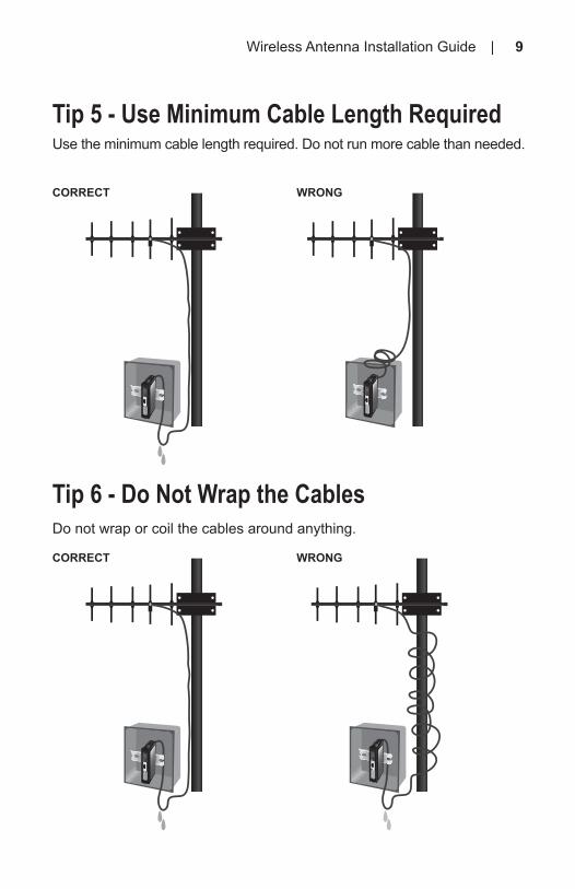
Tip 5 - Use Minimum Cable Length RequiredUse the minimum cable length required. Do not run more cable than needed.
Tip 6 - Do Not Wrap the Cables Do not wrap or coil the cables around anything.
CORRECT WRONG
WRONG

8 | How to Choose the Right Antenna
N-Female-0.5 dB
-1 dB
-0.5 dB
-0.5 dB
10 ft cable
1 ft cable
N-Male
N-Male
N-Male
RP-SMA
Radio
Lightning Arrestor
N-Female
N-Female
-0.5 dB
-0.5 dB
-0.5 dB
-0.5 dB
-1 dB
100 ft cable
5 ft cable
N-Male
N-Male
N-Male
N-Male
RP-SMA
Radio
Lightning Arrestor
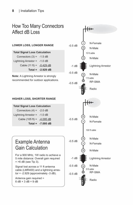
Total Signal Loss CalculationConnectors (3) = -1.5 dB
Lightning Arrestor = -1.0 dBCable (11 ft) = -0.429 dB
Total = -2.929 dB
Total Signal Loss CalculationConnectors (4) = -2.0 dB
Lightning Arrestor = -1.0 dBCable (105 ft) = -4.095 dB
Total = -7.095 dB
LOWER LOSS, LONGER RANGE
HIGHER LOSS, SHORTER RANGE
How Too Many Connectors Affect dB Loss
Example Antenna Gain CalculationFor a 900 MHz, 1W radio to achieve a 5 mile distance: Overall gain required = >6 dB (see Tip 3).
Signal lost across a 11 ft antenna cable (LMR400) and a lightning arres-tor = -2.929 (approximately -3 dB).
Antenna gain required = 6 dB + 3 dB = 9 dB
Note: A Lightning Arrestor is strongly recommended for outdoor applications.
RF Range is influenced by several factors. Proper consideration during installation will help enhance the signal strength and range ensuring reliable operation.
Tip 1 - Clear RF Path of ObstructionsMake sure the RF path is clear of obstructions. Antennas should be installed where they can “see” each other as much as possible. Make sure the antennas are high enough above any obstructions in the RF path.
CORRECT WRONG
Line of SightLine of Sight
Obstructions in the lobe of the radio signal
Wireless Antenna Installation Guide | 5
2 Wireless Antenna Installation Tips
SUGGESTED HEIGHT CLEAR OF OBSTRUCTIONS
Range 2.4 GHz 900 MHz 868 MHz1000 ft (300 m) 5.5 ft (1.7 m) 8 ft (2.5 m) 8.5 ft (2.6 m)1 mi (1.6 km) 10.5 ft (3.2 m) 16 ft (5 m) 19.4 ft (5.9 m)5 mi (8 km) — 34 ft (10.5 m) 46.6 ft (14.2 m)
10 mi (16 km) — 47.5 ft (14.5 m) 61 ft (18.6 m)
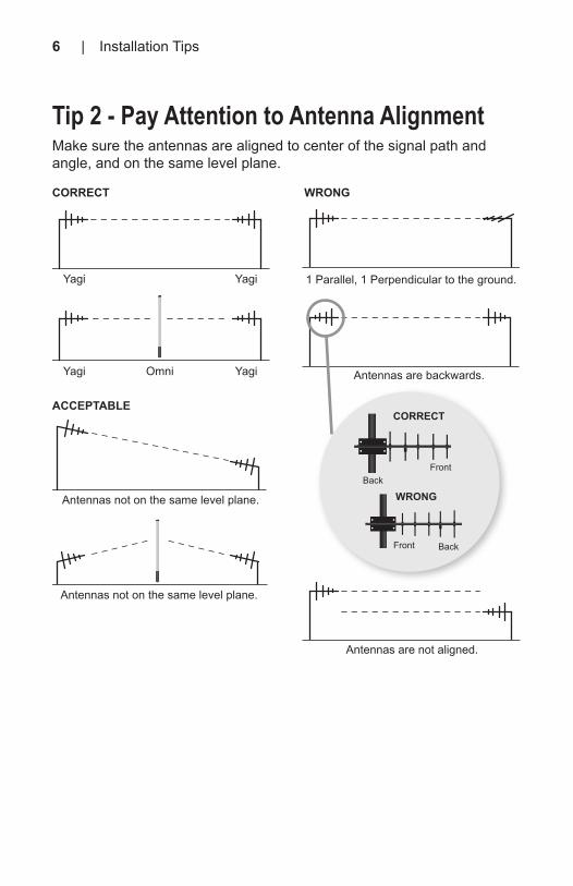
Tip 2 - Pay Attention to Antenna AlignmentMake sure the antennas are aligned to center of the signal path and angle, and on the same level plane.
Yagi
Yagi Omni
Yagi 1 Parallel, 1 Perpendicular to the ground.
Antennas are not aligned.
Antennas not on the same level plane.
Antennas not on the same level plane.
Antennas are backwards.Yagi
CORRECT
ACCEPTABLE
WRONG
6 | Installation Tips Wireless Antenna Installation Guide | 7
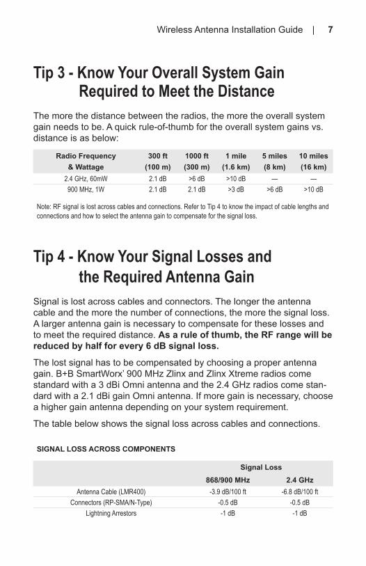
Tip 4 - Know Your Signal Losses and the Required Antenna GainSignal is lost across cables and connectors. The longer the antenna cable and the more the number of connections, the more the signal loss. A larger antenna gain is necessary to compensate for these losses and to meet the required distance. As a rule of thumb, the RF range will be reduced by half for every 6 dB signal loss.
The lost signal has to be compensated by choosing a proper antenna gain. B+B SmartWorx’ 900 MHz Zlinx and Zlinx Xtreme radios come standard with a 3 dBi Omni antenna and the 2.4 GHz radios come stan-dard with a 2.1 dBi gain Omni antenna. If more gain is necessary, choose a higher gain antenna depending on your system requirement.
The table below shows the signal loss across cables and connections.
Tip 3 - Know Your Overall System Gain Required to Meet the DistanceThe more the distance between the radios, the more the overall system gain needs to be. A quick rule-of-thumb for the overall system gains vs. distance is as below:
Radio Frequency & Wattage
300 ft (100 m)
1000 ft (300 m)
1 mile (1.6 km)
5 miles (8 km)
10 miles (16 km)
2.4 GHz, 60mW 2.1 dB >6 dB >10 dB — —900 MHz, 1W 2.1 dB 2.1 dB >3 dB >6 dB >10 dB
Note: RF signal is lost across cables and connections. Refer to Tip 4 to know the impact of cable lengths and connections and how to select the antenna gain to compensate for the signal loss.
SIGNAL LOSS ACROSS COMPONENTS
Signal Loss868/900 MHz 2.4 GHz
Antenna Cable (LMR400) -3.9 dB/100 ft -6.8 dB/100 ftConnectors (RP-SMA/N-Type) -0.5 dB -0.5 dB
Lightning Arrestors -1 dB -1 dB
Back
Back
Front
Front
CORRECT
WRONG
Tip 2 - Pay Attention to Antenna AlignmentMake sure the antennas are aligned to center of the signal path and angle, and on the same level plane.
Yagi
Yagi Omni
Yagi 1 Parallel, 1 Perpendicular to the ground.
Antennas are not aligned.
Antennas not on the same level plane.
Antennas not on the same level plane.
Antennas are backwards.Yagi
CORRECT
ACCEPTABLE
WRONG
6 | Installation Tips Wireless Antenna Installation Guide | 7
Tip 4 - Know Your Signal Losses and the Required Antenna GainSignal is lost across cables and connectors. The longer the antenna cable and the more the number of connections, the more the signal loss. A larger antenna gain is necessary to compensate for these losses and to meet the required distance. As a rule of thumb, the RF range will be reduced by half for every 6 dB signal loss.
The lost signal has to be compensated by choosing a proper antenna gain. B+B SmartWorx’ 900 MHz Zlinx and Zlinx Xtreme radios come standard with a 3 dBi Omni antenna and the 2.4 GHz radios come stan-dard with a 2.1 dBi gain Omni antenna. If more gain is necessary, choose a higher gain antenna depending on your system requirement.
The table below shows the signal loss across cables and connections.
Tip 3 - Know Your Overall System Gain Required to Meet the DistanceThe more the distance between the radios, the more the overall system gain needs to be. A quick rule-of-thumb for the overall system gains vs. distance is as below:
Radio Frequency & Wattage
300 ft (100 m)
1000 ft (300 m)
1 mile (1.6 km)
5 miles (8 km)
10 miles (16 km)
2.4 GHz, 60mW 2.1 dB >6 dB >10 dB — —900 MHz, 1W 2.1 dB 2.1 dB >3 dB >6 dB >10 dB
Note: RF signal is lost across cables and connections. Refer to Tip 4 to know the impact of cable lengths and connections and how to select the antenna gain to compensate for the signal loss.
SIGNAL LOSS ACROSS COMPONENTS
Signal Loss868/900 MHz 2.4 GHz
Antenna Cable (LMR400) -3.9 dB/100 ft -6.8 dB/100 ftConnectors (RP-SMA/N-Type) -0.5 dB -0.5 dB
Lightning Arrestors -1 dB -1 dB
Back
Back
Front
Front
CORRECT
WRONG
8 | Installation Tips
N-Female-0.5 dB
-1 dB
-0.5 dB
-0.5 dB
10 ft cable
1 ft cable
N-Male
N-Male
N-Male
RP-SMA
Radio
Lightning Arrestor
N-Female
N-Female
-0.5 dB
-0.5 dB
-0.5 dB
-0.5 dB
-1 dB
100 ft cable
5 ft cable
N-Male
N-Male
N-Male
N-Male
RP-SMA
Radio
Lightning Arrestor
Total Signal Loss CalculationConnectors (3) = -1.5 dB
Lightning Arrestor = -1.0 dBCable (11 ft) = -0.429 dB
Total = -2.929 dB
Total Signal Loss CalculationConnectors (4) = -2.0 dB
Lightning Arrestor = -1.0 dBCable (105 ft) = -4.095 dB
Total = -7.095 dB
LOWER LOSS, LONGER RANGE
HIGHER LOSS, SHORTER RANGE
How Too Many Connectors Affect dB Loss
Example Antenna Gain CalculationFor a 900 MHz, 1W radio to achieve a 5 mile distance: Overall gain required = >6 dB (see Tip 3).
Signal lost across a 11 ft antenna cable (LMR400) and a lightning arres-tor = -2.929 (approximately -3 dB).
Antenna gain required = 6 dB + 3 dB = 9 dB
Note: A Lightning Arrestor is strongly recommended for outdoor applications.
RF Range is influenced by several factors. Proper consideration during installation will help enhance the signal strength and range ensuring reliable operation.
Tip 1 - Clear RF Path of ObstructionsMake sure the RF path is clear of obstructions. Antennas should be installed where they can “see” each other as much as possible. Make sure the antennas are high enough above any obstructions in the RF path.
CORRECT WRONG
Line of SightLine of Sight
Obstructions in the lobe of the radio signal
Wireless Antenna Installation Guide | 5
2 Wireless Antenna Installation Tips
SUGGESTED HEIGHT CLEAR OF OBSTRUCTIONS
Range 2.4 GHz 900 MHz 868 MHz1000 ft (300 m) 5.5 ft (1.7 m) 8 ft (2.5 m) 8.5 ft (2.6 m)1 mi (1.6 km) 10.5 ft (3.2 m) 16 ft (5 m) 19.4 ft (5.9 m)5 mi (8 km) — 34 ft (10.5 m) 46.6 ft (14.2 m)
10 mi (16 km) — 47.5 ft (14.5 m) 61 ft (18.6 m)
Point-to-PointIn this configuration, two radios will be talking to one another. Typical examples are serial-to-serial communication or peer-to-peer I/O wire replacement systems. Yagi antennas at both ends increase signal strength, range and reduce interference.
Point-to-MultipointIn a multipoint system, an Omni antenna is typically used as the master with individual Yagi antennas as “slaves” pointing to the “master” antenna for the best range and signal strength. A typical example is Modbus I/O configuration with a Radio Modem connected to an RTU master with several I/O nodes as slaves.
When transmitting, a Yagi antenna allows more transmitted power to be sent in the direction of the receiver, increasing the received signal strength. When receiving, a Yagi antenna captures more of the signal, increasing signal strength. This also reduces interference.
Clear Line of Sight Required
Clear Line of Sight Required
Slave Master Slave
4 | How to Choose the Right Antenna Wireless Antenna Installation Guide | 9
CORRECT
Tip 5 - Use Minimum Cable Length RequiredUse the minimum cable length required. Do not run more cable than needed.
Tip 6 - Do Not Wrap the Cables Do not wrap or coil the cables around anything.
CORRECT WRONG
WRONG
10 | Installation Tips
Tip 7 - Use Drip LoopsUse drip loops at the cabinet. This keeps moisture from collecting be-tween the connection joints and in the cabinet itself. When using cabinets, bottom cable entry is recommended versus side entry. Never run the cable in through the top of your cabinet.
CORRECT WRONG
WRONG
CORRECT
WRONG
Omni AntennaOmni-directional antennas focus their energy equally in all directions. They typically have lesser range than a Yagi antenna of similar gain. Omni antennas are used in point-to-multipoint applications for the central master unit.
Omni-Directional Antenna
Y
Azimuth
X
Z
Y
Elevation
Z
Y
XBase Station Radiation Pattern
Wireless Antenna Installation Guide | 3
Yagi AntennaA directional antenna. Focuses energy to one particular direction. In a point-to-point application, it is ideal to use Yagi antennas at both locations for extended range and better signal strength. Yagi antennas generate the best results in point-to-multipoint applications when used with remote slave radios.
High Gain Yagi Antenna
Back
Front
Y
X
Azimuth
Y
Z
Elevation
Z
X
Yagi Radiating Pattern
1 How to Choose the Right Antenna
2 | How to Choose the Right Antenna Wireless Antenna Installation Guide | 11
Tip 8 - Protect the Antenna Connection Protect the antenna connection with the correct vulcanizing rubberized tape.
CORRECT WRONG
CORRECT WRONG
90° out of phase
90° out of phase
Tip 10 - Correctly Phase Yagis with Respect to Each OtherMake sure Yagis are phased (oriented) correctly with respect to each other.
Tip 9 - Correctly Phase the Yagi with Respect to the Omni Base AntennaMake sure Yagis are phased (oriented) correctly with respect to the Omni base antenna.
12 | Additional Resources
RANGE VARIABLES AND THEIR IMPACT
Range Variable RF Range Reducer RF Range EnhancerTransmitter Power Less MoreReceiver Sensitivity More LessAntenna Gain Less MoreAntenna Cable Length More LessNumber of Connectors More LessPhysical Obstructions More LessRadio Frequency Interference More LessData Rate More Less
The table below shows the maximum distance for different antenna and cable combinations at different terrains. Impact of weather is not factored in.
HOW WILL ENVIRONMENTAL CONDITIONS AFFECT MY ANTENNA CHOICE?
2.4 GHz Models 868/900 MHz ModelsIndoor: No line of sight, limited number of frame-construction walls, multiple reflective surfaces
500 ft (150 m) Supplied antenna Supplied antenna500-2600 ft (150-750 m) — Supplied antenna
Outdoor Unobstructed: Perfect RF conditions: Tower to TowerUp to 1.4 mi (2.25 km) Supplied antenna (no cable) Supplied antenna (no cable)
5 mi (8 km) Omni (10 ft / 3 m cable) Yagi (20 ft / 6 m cable)
Supplied antenna (no cable)
7 mi (11.2 km) Yagi (50 ft / 15 m cable) Supplied antenna (no cable)10 mi (16 km) Yagi (20 ft / 6 m cable) Supplied antenna (no cable)
14 mi (22.5 km) — Omni (50 ft / 15 m cable) Yagi (50 ft / 15 m cable)
40 mi (64 km) — Yagi (50 ft cable)Outdoor Rural: Clear line of sight with elevated antennas and no obstructions
Up to 2900 ft (870 m) Supplied antenna (no cable) Supplied antenna (no cable)1 mi (1.6 km) Omni (20 ft / 6 m cable)
Yagi (50 ft / 15 m cable)Supplied antenna (no cable)
1.5 mi (2.4 km) Omni (10 ft / 3 m cable) Yagi (50 ft / 15 m cable)
Supplied antenna (no cable)
3 mi (4.8 km) Yagi (20 ft / 6 m cable) Supplied antenna (no cable)7 mi (11.2 km) — Omni (10 ft / 3 m cable)
Yagi (50 ft / 15 m cable)10 mi (16 km) — Yagi (50 ft / 15 m cable)20 mi (32 km) — Yagi (10 ft / 3 m cable)
3 Additional Resources Table of Contents
1 How to Choose the Right Antenna . . . . . . . . . . . . . . . . 2
Yagi Antennas . . . . . . . . . . . . . . . . . . . . . . . . 2
Omni Antennas . . . . . . . . . . . . . . . . . . . . . . . . 3
2 Wireless Antenna Installation Tips . . . . . . . . . . . . . . . . 5
Tip 1 - Clear RF Path of Obstructions . . . . . . . . . . . . . . . 5
Tip 2 - Pay Attention to Antenna Alignment . . . . . . . . . . . . . 6
Tip 3 - Know Your Overall System Gain Required to Meet the Distance . . 7
Tip 4 - Know Your Signal Losses and the Required Antenna Gain . . . . 7
Tip 5 - Use the Minimum Cable Length Required . . . . . . . . . . . 9
Tip 6 - Do Not Wrap the Cables . . . . . . . . . . . . . . . . . 9
Tip 7 - Use Drip Loops . . . . . . . . . . . . . . . . . . . . 10
Tip 8 - Protect the Antenna Connection . . . . . . . . . . . . . 11
Tip 9 - Correctly Phase the Yagi with Respect to the Omni Base Antenna 11
Tip 10 - Correctly Phase Yagis with Respect to Each Other . . . . . . 11
3 Additional Resources . . . . . . . . . . . . . . . . . . . . 12
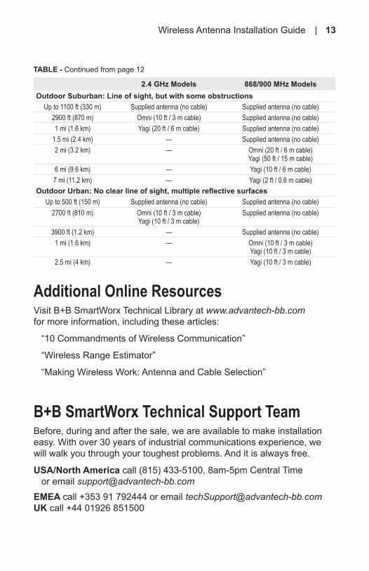
Additional Online ResourcesVisit B+B SmartWorx Technical Library at www.advantech-bb.comfor more information, including these articles:
“10 Commandments of Wireless Communication”
“Wireless Range Estimator”
“Making Wireless Work: Antenna and Cable Selection”
B+B SmartWorx Technical Support TeamBefore, during and after the sale, we are available to make installation easy. With over 30 years of industrial communications experience, we will walk you through your toughest problems. And it is always free.
USA/North America call (815) 433-5100, 8am-5pm Central Time or email [email protected] call +353 91 792444 or email [email protected] UK call +44 01926 851500
Wireless Antenna Installation Guide | 13
TABLE - Continued from page 12
2.4 GHz Models 868/900 MHz ModelsOutdoor Suburban: Line of sight, but with some obstructions
Up to 1100 ft (330 m) Supplied antenna (no cable) Supplied antenna (no cable)2900 ft (870 m) Omni (10 ft / 3 m cable) Supplied antenna (no cable)1 mi (1.6 km) Yagi (20 ft / 6 m cable) Supplied antenna (no cable)
1.5 mi (2.4 km) — Supplied antenna (no cable)2 mi (3.2 km) — Omni (20 ft / 6 m cable)
Yagi (50 ft / 15 m cable)6 mi (9.6 km) — Yagi (10 ft / 6 m cable)7 mi (11.2 km) — Yagi (2 ft / 0.6 m cable)
Outdoor Urban: No clear line of sight, multiple reflective surfacesUp to 500 ft (150 m) Supplied antenna (no cable) Supplied antenna (no cable)
2700 ft (810 m) Omni (10 ft / 3 m cable) Yagi (10 ft / 3 m cable)
Supplied antenna (no cable)
3900 ft (1.2 km) — Supplied antenna (no cable)1 mi (1.6 km) — Omni (10 ft / 3 m cable)
Yagi (10 ft / 3 m cable)2.5 mi (4 km) — Yagi (10 ft / 3 m cable)

Wireless AntennaInstallation Guide
10 Tips for Making Your Wireless Installation a Success
Making Wireless EasyInternational Headquarters707 Dayton Road • PO Box 1040Ottawa, IL 61350 USAPhone: 815.433.5100 • Fax: 815.433.5109
Europe, Africa, Middle East10 Westlink Commercial ParkOranmore, Co. Galway, IrelandPhone: +353.91.792444 • Fax: +353.91.792445U.K. +44.01926.851500
Making Wireless Easy
Documentation #2417PN #8912www.advantech-bb.com