Embed Size (px)
Citation preview
Microchip Technology Inc.Web Seminar January 21, 2004
Wireless Communication using the IrDA® Standard Protocol Page 1
© 2004 Microchip Technology Incorporated. All Rights Reserved. Wireless Communication using the IrDA® Standard Protocol 1
Wireless Communicationusing the
IrDA® Standard Protocol
Thank YouMy name is Mark Palmer and I am the application engineer supportingMicrochip�s family of IrDA Standard Protocol Handling devices. Today we willbe giving a brief introduction to wireless communication using the IrDAStandard protocol.
Microchip Technology Inc.Web Seminar January 21, 2004
Wireless Communication using the IrDA® Standard Protocol Page 2
© 2004 Microchip Technology Incorporated. All Rights Reserved. Wireless Communication using the IrDA® Standard Protocol 2
Agenda� Why use infrared?� Typical applications� An IrDA® Standard system� IrDA protocol stack� Connection sequence� Host UART interface� Complete support� Summary
This agenda gives you an idea of the topics we will cover. First we willdiscuss why use infrared, and what are some of the typical applications. Wewill then give a high level look at an IrDA Standard system. From this systemwe will discuss the IrDA protocol stack, the connection sequence that occurson the IR interface, and then the Host UART interface between the MicrochipProtocol Handler (MCP215x/MCP2140) and the Host Controller. We will thenwrap up with what Microchip offers to support this product family.
Microchip Technology Inc.Web Seminar January 21, 2004
Wireless Communication using the IrDA® Standard Protocol Page 3
© 2004 Microchip Technology Incorporated. All Rights Reserved. Wireless Communication using the IrDA® Standard Protocol 3
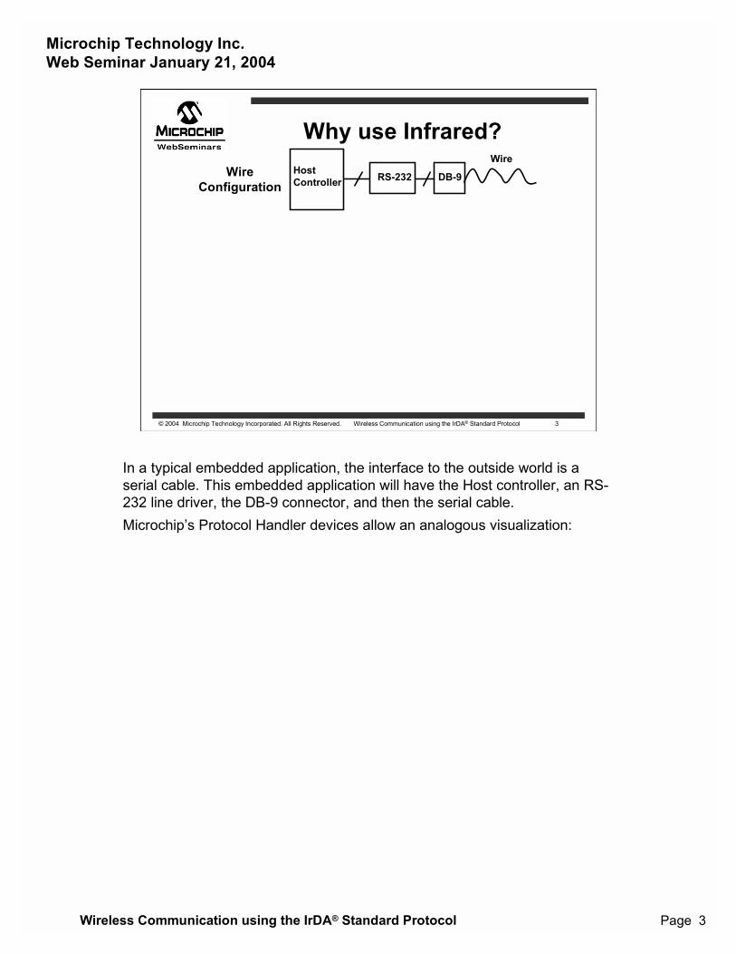
Why use Infrared?Wire
ConfigurationRS-232 DB-9Host
Controller
Wire
In a typical embedded application, the interface to the outside world is aserial cable. This embedded application will have the Host controller, an RS-232 line driver, the DB-9 connector, and then the serial cable.Microchip�s Protocol Handler devices allow an analogous visualization:
Microchip Technology Inc.Web Seminar January 21, 2004
Wireless Communication using the IrDA® Standard Protocol Page 4
© 2004 Microchip Technology Incorporated. All Rights Reserved. Wireless Communication using the IrDA® Standard Protocol 4
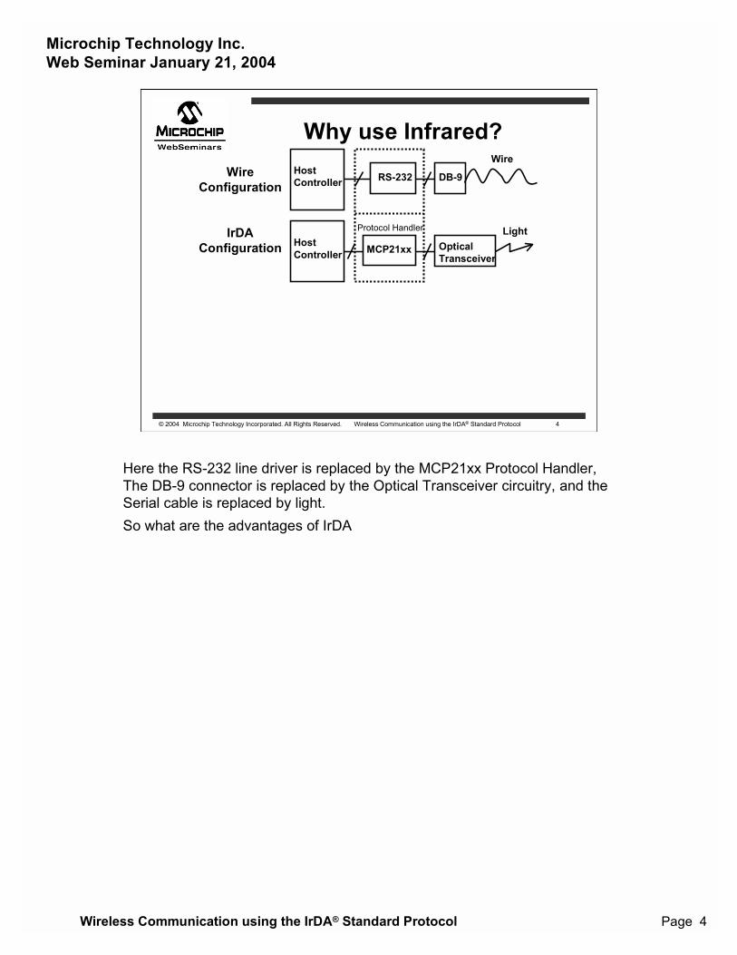
Why use Infrared?Wire
ConfigurationRS-232 DB-9Host
Controller
Wire
MCP21xx OpticalTransceiver
HostController
LightIrDAConfiguration
Protocol Handler
Here the RS-232 line driver is replaced by the MCP21xx Protocol Handler,The DB-9 connector is replaced by the Optical Transceiver circuitry, and theSerial cable is replaced by light.So what are the advantages of IrDA
Microchip Technology Inc.Web Seminar January 21, 2004
Wireless Communication using the IrDA® Standard Protocol Page 5
© 2004 Microchip Technology Incorporated. All Rights Reserved. Wireless Communication using the IrDA® Standard Protocol 5
Why use Infrared?
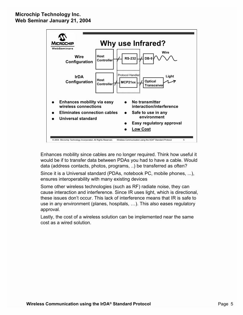
� Enhances mobility via easywireless connections
� Eliminates connection cables� Universal standard
� No transmitter interaction/interference
� Safe to use in anyenvironment
� Easy regulatory approval� Low Cost
WireConfiguration
RS-232 DB-9HostController
Wire
MCP21xx OpticalTransceiver
HostController
LightIrDAConfiguration
Protocol Handler
Enhances mobility since cables are no longer required. Think how useful itwould be if to transfer data between PDAs you had to have a cable. Woulddata (address contacts, photos, programs, ..) be transferred as often?Since it is a Universal standard (PDAs, notebook PC, mobile phones, ...),ensures interoperability with many existing devicesSome other wireless technologies (such as RF) radiate noise, they cancause interaction and interference. Since IR uses light, which is directional,these issues don�t occur. This lack of interference means that IR is safe touse in any environment (planes, hospitals, �). This also eases regulatoryapproval.Lastly, the cost of a wireless solution can be implemented near the samecost as a wired solution.
Microchip Technology Inc.Web Seminar January 21, 2004
Wireless Communication using the IrDA® Standard Protocol Page 6
© 2004 Microchip Technology Incorporated. All Rights Reserved. Wireless Communication using the IrDA® Standard Protocol 6
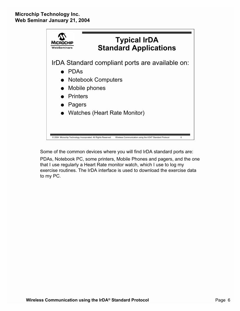
Typical IrDAStandard Applications
IrDA Standard compliant ports are available on:� PDAs� Notebook Computers� Mobile phones� Printers� Pagers� Watches (Heart Rate Monitor)
Some of the common devices where you will find IrDA standard ports are:PDAs, Notebook PC, some printers, Mobile Phones and pagers, and the onethat I use regularly a Heart Rate monitor watch, which I use to log myexercise routines. The IrDA interface is used to download the exercise datato my PC.
Microchip Technology Inc.Web Seminar January 21, 2004
Wireless Communication using the IrDA® Standard Protocol Page 7
© 2004 Microchip Technology Incorporated. All Rights Reserved. Wireless Communication using the IrDA® Standard Protocol 7
An Embedded SystemHost
Controller
TX
RX
UAR
TEncode
Decode
TX TXIR
RX RXIR
MCP215X(Protocol Handler)
UARTControl
RTSCTSDSRDTR
CDRI
OpticalTransceiver
TXD
RXD
Protocol Handler
SecondaryDevice
Host Interface
Primary DeviceDevice (PDA)
with IrDA StandardInfrared Port
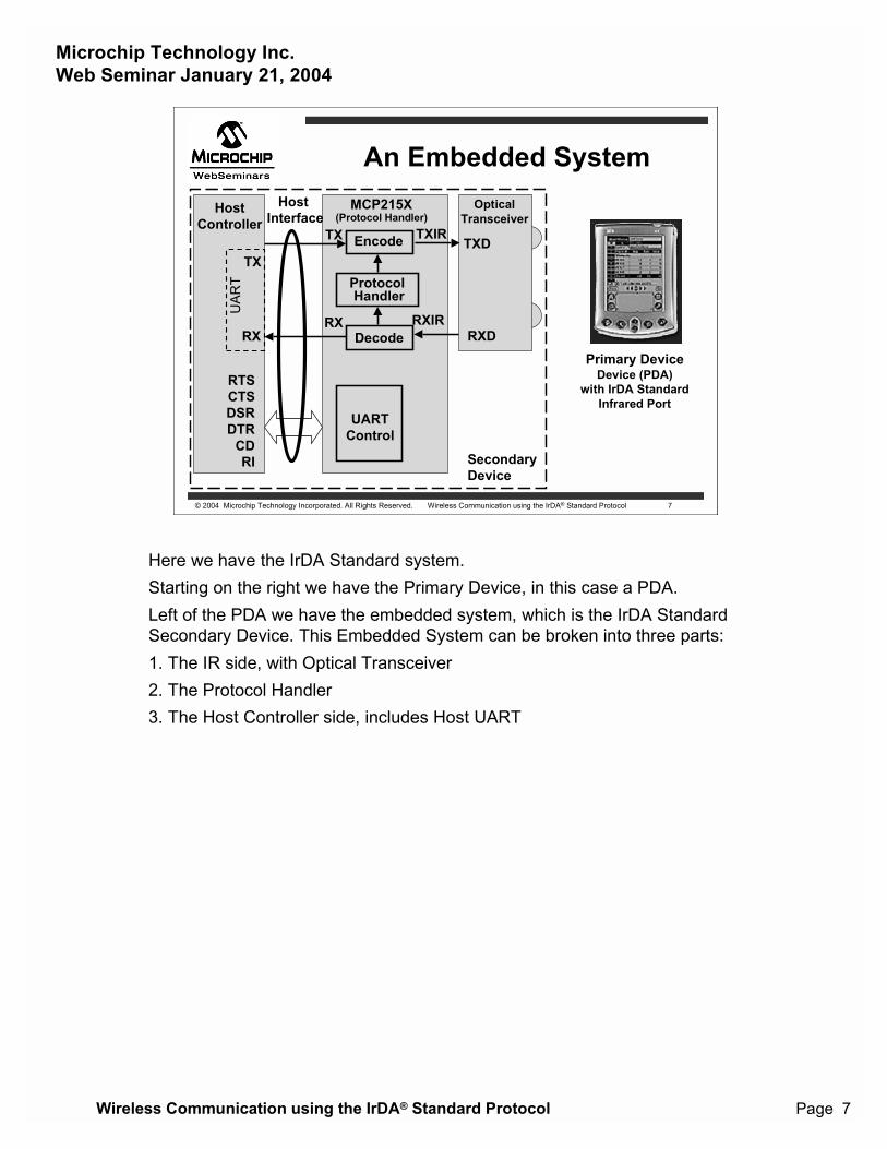
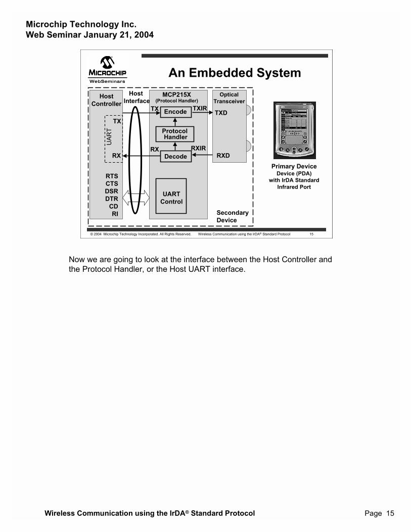
Here we have the IrDA Standard system.Starting on the right we have the Primary Device, in this case a PDA.Left of the PDA we have the embedded system, which is the IrDA StandardSecondary Device. This Embedded System can be broken into three parts:1. The IR side, with Optical Transceiver2. The Protocol Handler3. The Host Controller side, includes Host UART
Microchip Technology Inc.Web Seminar January 21, 2004
Wireless Communication using the IrDA® Standard Protocol Page 8
© 2004 Microchip Technology Incorporated. All Rights Reserved. Wireless Communication using the IrDA® Standard Protocol 8
The IrDA Protocol �Stack�
Optional IrDA Data Protocols not
Implemented in the MCP215x and MCP2140
Note 1: The MCP215X and MCP2140 implements the 9-wire �cooked" service class serial replicator
implemented in the MCP215X and MCP2140
2: An Optical Transceiver is required
AsynchronousSerial IR (2, 3, 4) (SIR)(9600 - 115200 Baud)
SynchronousSerial IR(1.15 MBaud)
SynchronousFast IR (FIR)(4 MBaud)
3: MCP2120 only implements the Encoding/Decoding portion of Physical Layer4: MCP2140 operates at a fixed 9600 Baud
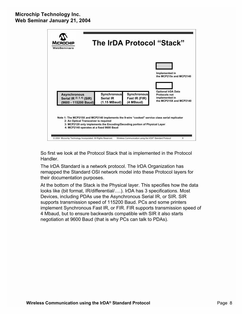
So first we look at the Protocol Stack that is implemented in the ProtocolHandler.The IrDA Standard is a network protocol. The IrDA Organization hasremapped the Standard OSI network model into these Protocol layers fortheir documentation purposes.At the bottom of the Stack is the Physical layer. This specifies how the datalooks like (bit format, IR/differential/�.). IrDA has 3 specifications. MostDevices, including PDAs use the Asynchronous Serial IR, or SIR. SIRsupports transmission speed of 115200 Baud. PCs and some printersimplement Synchronous Fast IR, or FIR. FIR supports transmission speed of4 Mbaud, but to ensure backwards compatible with SIR it also startsnegotiation at 9600 Baud (that is why PCs can talk to PDAs).
Microchip Technology Inc.Web Seminar January 21, 2004
Wireless Communication using the IrDA® Standard Protocol Page 9
© 2004 Microchip Technology Incorporated. All Rights Reserved. Wireless Communication using the IrDA® Standard Protocol 9
The IrDA Protocol �Stack�
Optional IrDA Data Protocols not
Implemented in the MCP215x and MCP2140
Note 1: The MCP215X and MCP2140 implements the 9-wire �cooked" service class serial replicator
implemented in the MCP215X and MCP2140
2: An Optical Transceiver is required
LM-IAS Tiny Transport Protocol (Tiny TP)
IR Link Management - Mux (IrLMP)
IR Link Access Protocol (IrLAP)AsynchronousSerial IR (2, 3, 4) (SIR)(9600 - 115200 Baud)
SynchronousSerial IR(1.15 MBaud)
SynchronousFast IR (FIR)(4 MBaud)
3: MCP2120 only implements the Encoding/Decoding portion of Physical Layer4: MCP2140 operates at a fixed 9600 Baud
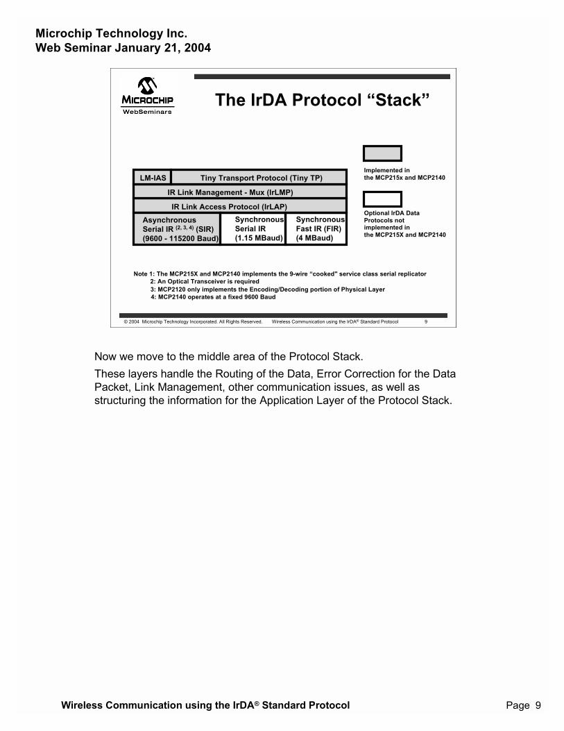
Now we move to the middle area of the Protocol Stack.These layers handle the Routing of the Data, Error Correction for the DataPacket, Link Management, other communication issues, as well asstructuring the information for the Application Layer of the Protocol Stack.
Microchip Technology Inc.Web Seminar January 21, 2004
Wireless Communication using the IrDA® Standard Protocol Page 10
© 2004 Microchip Technology Incorporated. All Rights Reserved. Wireless Communication using the IrDA® Standard Protocol 10
The IrDA Protocol �Stack�
Optional IrDA Data Protocols not
Implemented in the MCP215x and MCP2140
Note 1: The MCP215X and MCP2140 implements the 9-wire �cooked" service class serial replicator
implemented in the MCP215X and MCP2140
2: An Optical Transceiver is required
IrTRAN-P IrObex IrCOMM (1) IrMC
LM-IAS Tiny Transport Protocol (Tiny TP)
IR Link Management - Mux (IrLMP)
IR Link Access Protocol (IrLAP)AsynchronousSerial IR (2, 3, 4) (SIR)(9600 - 115200 Baud)
SynchronousSerial IR(1.15 MBaud)
SynchronousFast IR (FIR)(4 MBaud)
IrLAN
3: MCP2120 only implements the Encoding/Decoding portion of Physical Layer4: MCP2140 operates at a fixed 9600 Baud
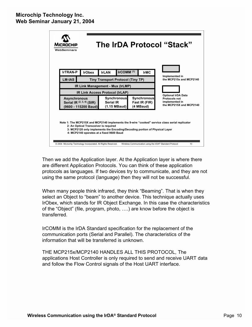
Then we add the Application layer. At the Application layer is where thereare different Application Protocols. You can think of these applicationprotocols as languages. If two devices try to communicate, and they are notusing the same protocol (language) then they will not be successful.
When many people think infrared, they think �Beaming�. That is when theyselect an Object to �beam� to another device. This technique actually usesIrObex, which stands for IR Object Exchange. In this case the characteristicsof the �Object� (file, program, photo, �.) are know before the object istransferred.
IrCOMM is the IrDA Standard specification for the replacement of thecommunication ports (Serial and Parallel). The characteristics of theinformation that will be transferred is unknown.
THE MCP215x/MCP2140 HANDLES ALL THIS PROTOCOL, Theapplications Host Controller is only required to send and receive UART dataand follow the Flow Control signals of the Host UART interface.
Microchip Technology Inc.Web Seminar January 21, 2004
Wireless Communication using the IrDA® Standard Protocol Page 11
© 2004 Microchip Technology Incorporated. All Rights Reserved. Wireless Communication using the IrDA® Standard Protocol 11
Connection Sequence
NormalDisconnectMode (NDM)
DiscoveryMode
NormalResponseMode (NRM)
When link is closed(or broken)
If link is closed(or broken)
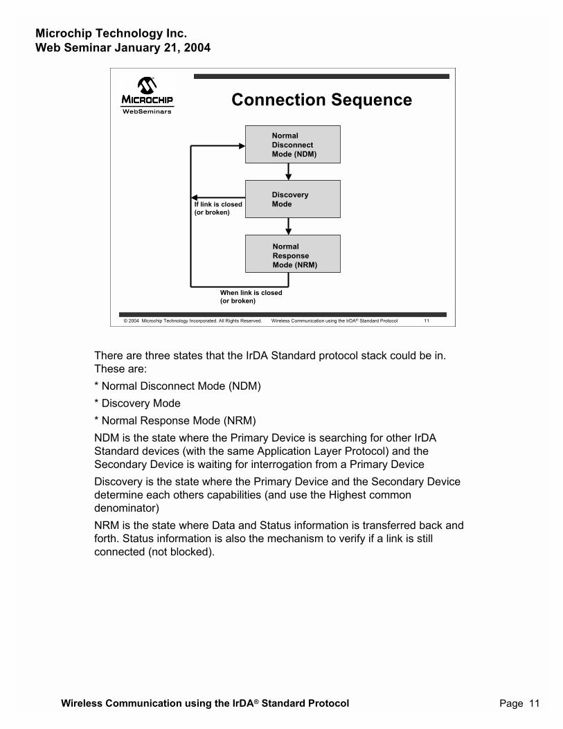
There are three states that the IrDA Standard protocol stack could be in.These are:* Normal Disconnect Mode (NDM)* Discovery Mode* Normal Response Mode (NRM)NDM is the state where the Primary Device is searching for other IrDAStandard devices (with the same Application Layer Protocol) and theSecondary Device is waiting for interrogation from a Primary DeviceDiscovery is the state where the Primary Device and the Secondary Devicedetermine each others capabilities (and use the Highest commondenominator)NRM is the state where Data and Status information is transferred back andforth. Status information is also the mechanism to verify if a link is stillconnected (not blocked).
Microchip Technology Inc.Web Seminar January 21, 2004
Wireless Communication using the IrDA® Standard Protocol Page 12
© 2004 Microchip Technology Incorporated. All Rights Reserved. Wireless Communication using the IrDA® Standard Protocol 12
Connection Sequence -Normal Disconnect Mode
Primary Device Secondary Device
No Response
Send XID Commands(timeslot n, n+1, �)
XID Response in timeslot y(claiming this timeslot)
No Response to these XIDs
No Response to Broadcast ID
Broadcast ID
Finish sending XIDs(max timeslot - y frames)
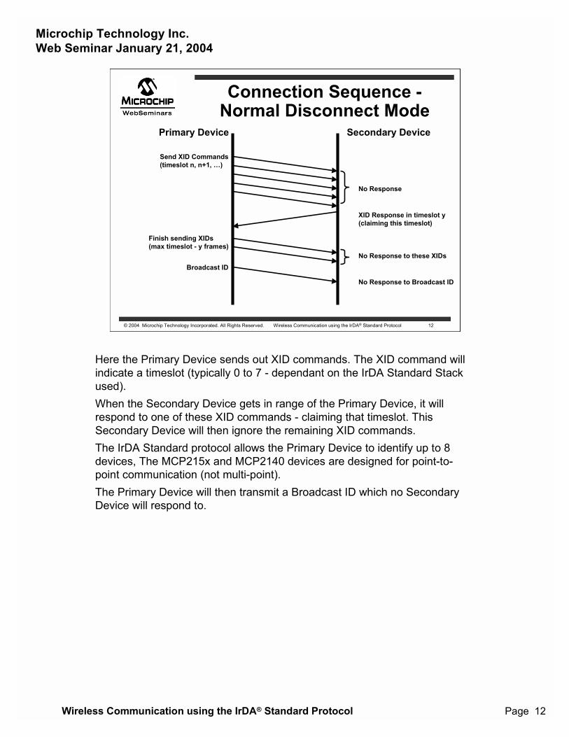
Here the Primary Device sends out XID commands. The XID command willindicate a timeslot (typically 0 to 7 - dependant on the IrDA Standard Stackused).When the Secondary Device gets in range of the Primary Device, it willrespond to one of these XID commands - claiming that timeslot. ThisSecondary Device will then ignore the remaining XID commands.The IrDA Standard protocol allows the Primary Device to identify up to 8devices, The MCP215x and MCP2140 devices are designed for point-to-point communication (not multi-point).The Primary Device will then transmit a Broadcast ID which no SecondaryDevice will respond to.
Microchip Technology Inc.Web Seminar January 21, 2004
Wireless Communication using the IrDA® Standard Protocol Page 13
© 2004 Microchip Technology Incorporated. All Rights Reserved. Wireless Communication using the IrDA® Standard Protocol 13
Connection Sequence -Discovery Mode
Primary Device Secondary Device
UA response with parametersusing connect address
Send SNRM Command(w/ parameters andconnection address)
Open channel for IASQueries
Confirm channel open for IAS
Send IAS Queries
Open channel for Data
Provide IAS responses
Confirm channel open for Data
MCP2150 - CD signal is lowMCP2155/MCP2140 - DSR signal is low
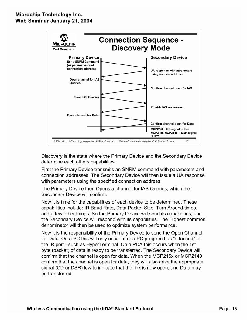
Discovery is the state where the Primary Device and the Secondary Devicedetermine each others capabilitiesFirst the Primary Device transmits an SNRM command with parameters andconnection addresses. The Secondary Device will then issue a UA responsewith parameters using the specified connection address.The Primary Device then Opens a channel for IAS Queries, which theSecondary Device will confirm.Now it is time for the capabilities of each device to be determined. Thesecapabilities include: IR Baud Rate, Data Packet Size, Turn Around times,and a few other things. So the Primary Device will send its capabilities, andthe Secondary Device will respond with its capabilities. The Highest commondenominator will then be used to optimize system performance.Now it is the responsibility of the Primary Device to send the Open Channelfor Data. On a PC this will only occur after a PC program has �attached� tothe IR port - such as HyperTerminal. On a PDA this occurs when the 1stbyte (packet) of data is ready to be transferred. The Secondary Device willconfirm that the channel is open for data. When the MCP215x or MCP2140confirm that the channel is open for data, they will also drive the appropriatesignal (CD or DSR) low to indicate that the link is now open, and Data maybe transferred
Microchip Technology Inc.Web Seminar January 21, 2004
Wireless Communication using the IrDA® Standard Protocol Page 14
© 2004 Microchip Technology Incorporated. All Rights Reserved. Wireless Communication using the IrDA® Standard Protocol 14
Connection Sequence -Normal Response Mode
Primary Device Secondary Device
Send Data or Status
Shutdown link
Confirm shutdown(back to NDM state
Send Data or Status
Send Data or Status
Send Data or Status
Confirm channel open for DataMCP2150 - CD signal is lowMCP2155/MCP2140 - DSR signal is low
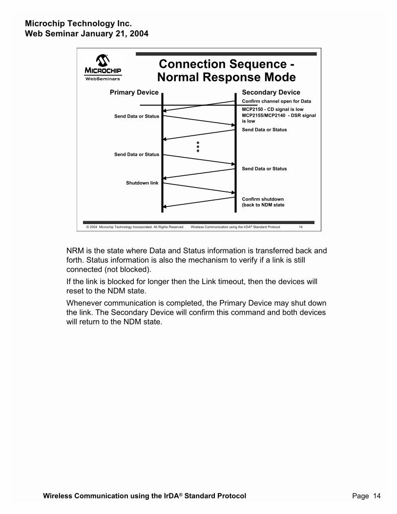
NRM is the state where Data and Status information is transferred back andforth. Status information is also the mechanism to verify if a link is stillconnected (not blocked).If the link is blocked for longer then the Link timeout, then the devices willreset to the NDM state.Whenever communication is completed, the Primary Device may shut downthe link. The Secondary Device will confirm this command and both deviceswill return to the NDM state.
Microchip Technology Inc.Web Seminar January 21, 2004
Wireless Communication using the IrDA® Standard Protocol Page 15
© 2004 Microchip Technology Incorporated. All Rights Reserved. Wireless Communication using the IrDA® Standard Protocol 15
An Embedded SystemHost
Controller
TX
RX
UAR
TEncode
Decode
TX TXIR
RX RXIR
MCP215X(Protocol Handler)
UARTControl
RTSCTSDSRDTR
CDRI
OpticalTransceiver
TXD
RXD
Protocol Handler
SecondaryDevice
Host Interface
Primary DeviceDevice (PDA)
with IrDA StandardInfrared Port
Now we are going to look at the interface between the Host Controller andthe Protocol Handler, or the Host UART interface.
Microchip Technology Inc.Web Seminar January 21, 2004
Wireless Communication using the IrDA® Standard Protocol Page 16
© 2004 Microchip Technology Incorporated. All Rights Reserved. Wireless Communication using the IrDA® Standard Protocol 16
Host UART HardwareHandshaking - continued
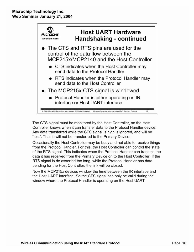
� The CTS and RTS pins are used for thecontrol of the data flow between theMCP215x/MCP2140 and the Host Controller� CTS indicates when the Host Controller may
send data to the Protocol Handler� RTS indicates when the Protocol Handler may
send data to the Host Controller� The MCP215x CTS signal is windowed
� Protocol Handler is either operating on IRinterface or Host UART interface
The CTS signal must be monitored by the Host Controller, so the HostController knows when it can transfer data to the Protocol Handler device.Any data transferred while the CTS signal is high is ignored, and will be�lost�. That is will not be transferred to the Primary Device.Occasionally the Host Controller may be busy and not able to receive thingsfrom the Protocol Handler. For this, the Host Controller can control the stateof the RTS signal. This indicates when the Protocol Handler can transmit thedata it has received from the Primary Device on to the Host Controller. If theRTS signal is de asserted too long, while the Protocol Handler has datapending for the Host Controller, the link will be closed.Now the MCP215x devices window the time between the IR interface andthe Host UART interface. So the CTS signal can only be valid during thewindow where the Protocol Handler is operating on the Host UART
Microchip Technology Inc.Web Seminar January 21, 2004
Wireless Communication using the IrDA® Standard Protocol Page 17
© 2004 Microchip Technology Incorporated. All Rights Reserved. Wireless Communication using the IrDA® Standard Protocol 17
Host UART HardwareHandshaking - continued
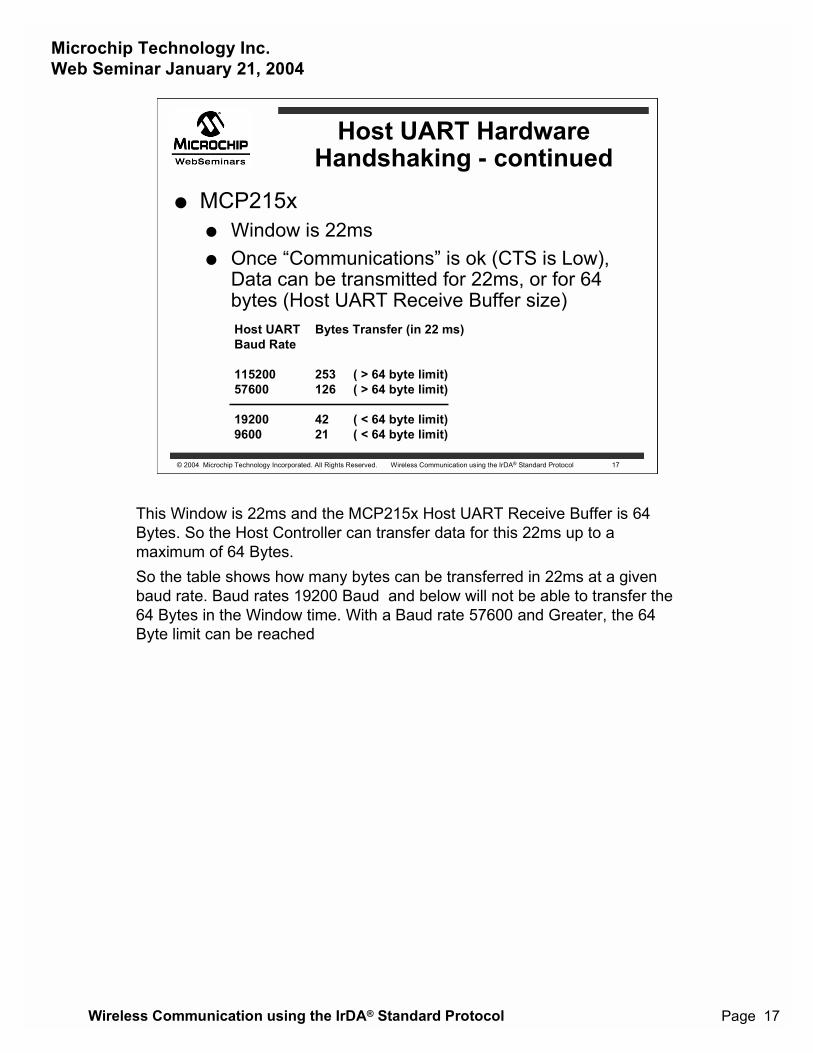
� MCP215x� Window is 22ms� Once �Communications� is ok (CTS is Low),
Data can be transmitted for 22ms, or for 64bytes (Host UART Receive Buffer size)Host UARTBaud Rate
11520057600
192009600
Bytes Transfer (in 22 ms)
253 ( > 64 byte limit)126 ( > 64 byte limit)
42 ( < 64 byte limit)21 ( < 64 byte limit)
This Window is 22ms and the MCP215x Host UART Receive Buffer is 64Bytes. So the Host Controller can transfer data for this 22ms up to amaximum of 64 Bytes.So the table shows how many bytes can be transferred in 22ms at a givenbaud rate. Baud rates 19200 Baud and below will not be able to transfer the64 Bytes in the Window time. With a Baud rate 57600 and Greater, the 64Byte limit can be reached
Microchip Technology Inc.Web Seminar January 21, 2004
Wireless Communication using the IrDA® Standard Protocol Page 18
© 2004 Microchip Technology Incorporated. All Rights Reserved. Wireless Communication using the IrDA® Standard Protocol 18
MCP215x CTSHardware Handshaking
CTS
Receive Buffer Empty, MCP215x can Receive Data
Receive Buffer has received 60 bytes (Baud Rate ≥ 57600), CTS pin is driven high, Receive Data Time Window still open
Receive Data Time Window (22ms)
Receive Data Time Window closed,MCP215x will transmit data later. Data will be processed and formatted
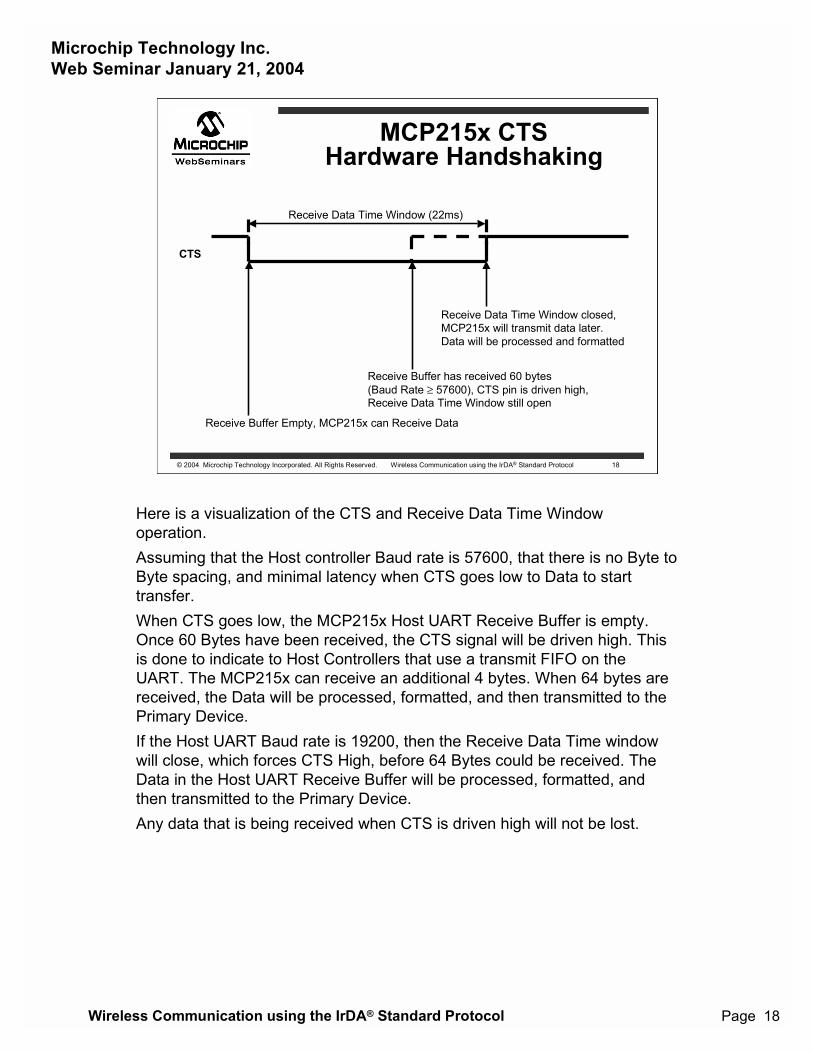
Here is a visualization of the CTS and Receive Data Time Windowoperation.Assuming that the Host controller Baud rate is 57600, that there is no Byte toByte spacing, and minimal latency when CTS goes low to Data to starttransfer.When CTS goes low, the MCP215x Host UART Receive Buffer is empty.Once 60 Bytes have been received, the CTS signal will be driven high. Thisis done to indicate to Host Controllers that use a transmit FIFO on theUART. The MCP215x can receive an additional 4 bytes. When 64 bytes arereceived, the Data will be processed, formatted, and then transmitted to thePrimary Device.If the Host UART Baud rate is 19200, then the Receive Data Time windowwill close, which forces CTS High, before 64 Bytes could be received. TheData in the Host UART Receive Buffer will be processed, formatted, andthen transmitted to the Primary Device.Any data that is being received when CTS is driven high will not be lost.
Microchip Technology Inc.Web Seminar January 21, 2004
Wireless Communication using the IrDA® Standard Protocol Page 19
© 2004 Microchip Technology Incorporated. All Rights Reserved. Wireless Communication using the IrDA® Standard Protocol 19
MCP2140 CTSHardware Handshaking
CTS
Receive Buffer Empty, MCP215x can Receive Data
Receive Buffer has received 23 bytes,CTS pin is driven high, Receive Buffer may still receive 6 bytes
Receive Buffer Full (29 Bytes),MCP2140 will transmit data later. Data will be processed and formatted
Receive Buffer Empty, MCP215x can Receive Data
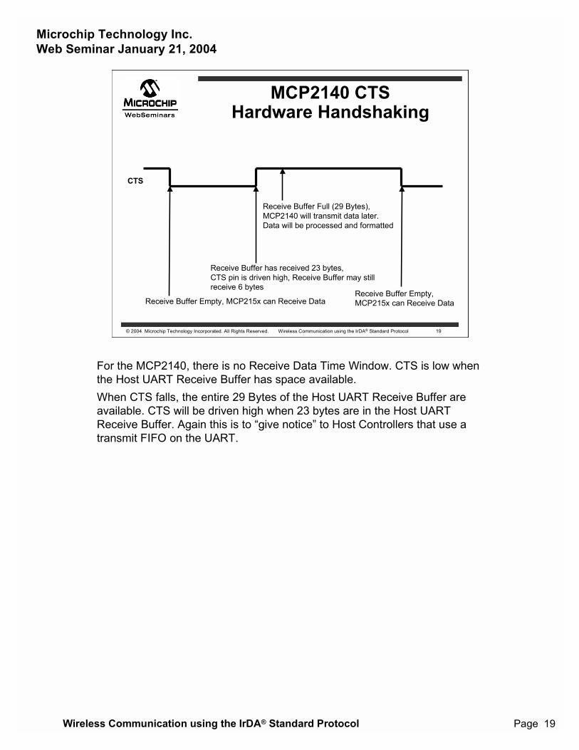
For the MCP2140, there is no Receive Data Time Window. CTS is low whenthe Host UART Receive Buffer has space available.When CTS falls, the entire 29 Bytes of the Host UART Receive Buffer areavailable. CTS will be driven high when 23 bytes are in the Host UARTReceive Buffer. Again this is to �give notice� to Host Controllers that use atransmit FIFO on the UART.
Microchip Technology Inc.Web Seminar January 21, 2004
Wireless Communication using the IrDA® Standard Protocol Page 20
© 2004 Microchip Technology Incorporated. All Rights Reserved. Wireless Communication using the IrDA® Standard Protocol 20
Complete Support SolutionHost
Controller
TX
RX
UAR
TEncode
Decode
TX TXIR
RX RXIR
MCP215X(Protocol Handler)
UARTControl
RTSCTSDSRDTR
CDRI
OpticalTransceiver
TXD
RXD
Protocol Handler
SecondaryDevice
Host Interface
Primary Devicewith IrDAStandardInfrared Port(PDAs,NotebookPC, �)
App Notes Available:� Programming the Palm® OS(AN888)� Discrete Transceiver design (AN243)
In Development:� Programming Pocket PC� Programming Windows® XP
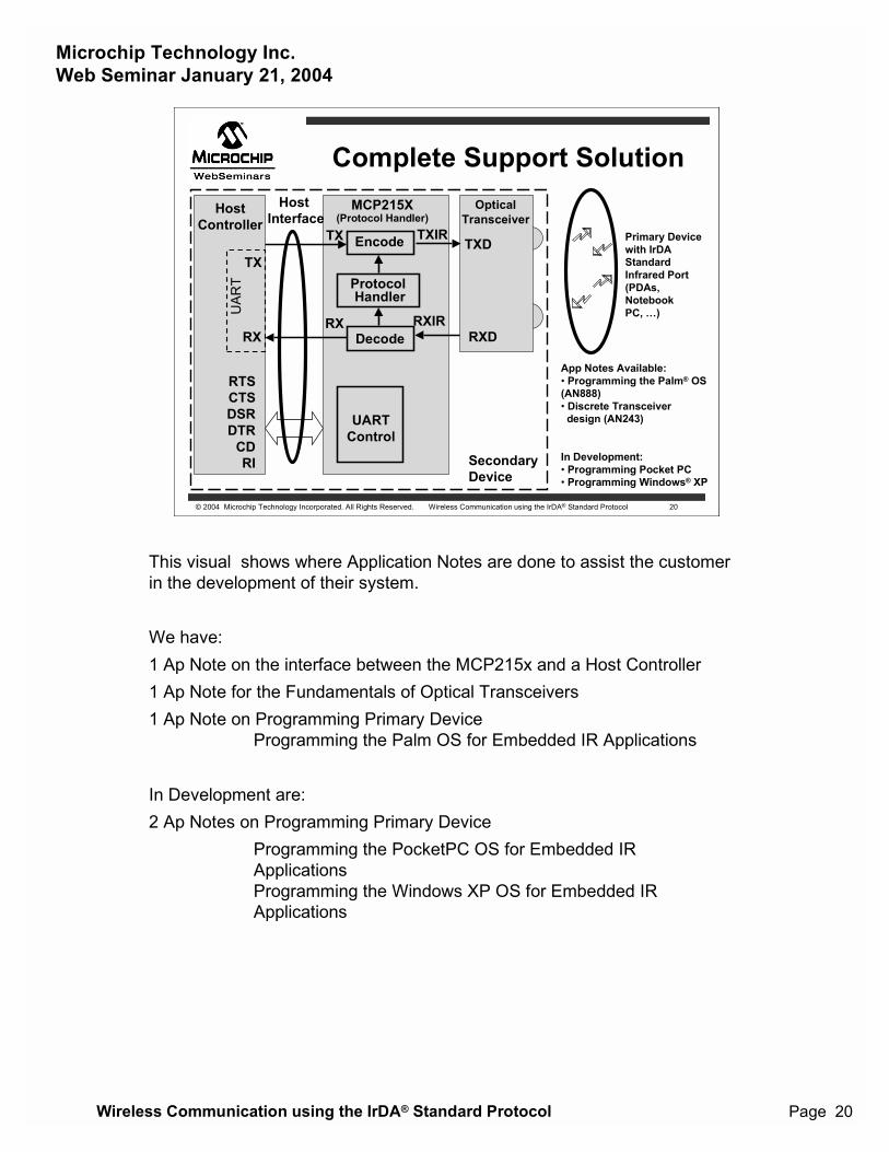
This visual shows where Application Notes are done to assist the customerin the development of their system.
We have:1 Ap Note on the interface between the MCP215x and a Host Controller1 Ap Note for the Fundamentals of Optical Transceivers1 Ap Note on Programming Primary Device
Programming the Palm OS for Embedded IR Applications
In Development are:2 Ap Notes on Programming Primary Device
Programming the PocketPC OS for Embedded IRApplicationsProgramming the Windows XP OS for Embedded IRApplications
Microchip Technology Inc.Web Seminar January 21, 2004
Wireless Communication using the IrDA® Standard Protocol Page 21
© 2004 Microchip Technology Incorporated. All Rights Reserved. Wireless Communication using the IrDA® Standard Protocol 21
Summary
� Microchip�s family of IrDA® StandardProtocol Handles enables wirelessconnectivity to easily be added to embeddedapplications.
� This universal interface allows commonlyavailable low cost devices, such as PDAs, tointerface to the embedded system.
Microchip�s IrDA Standard Protocol Handler devices can easily be added tosystems currently using a serial connection with flow control. This whenallows these embedded systems to interface to the many existing deviceswith an IrDA port.List of some of the available Application Notes, Data Sheets, and otherreference material is available on the next couple of slides. For a completelist of Information Please visit the Infrared Communication Design page ofthe Microchip Web Site.
Microchip Technology Inc.Web Seminar January 21, 2004
Wireless Communication using the IrDA® Standard Protocol Page 22
© 2004 Microchip Technology Incorporated. All Rights Reserved. Wireless Communication using the IrDA® Standard Protocol 22
Documentation Support� Data sheets:
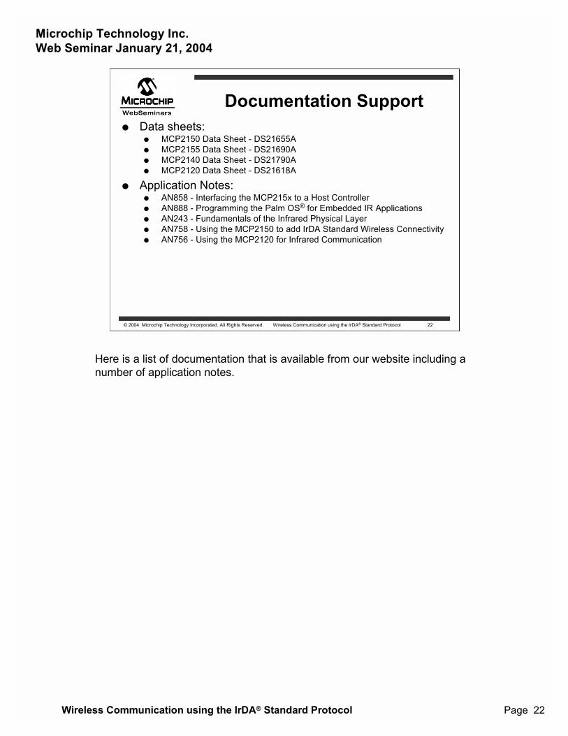
� MCP2150 Data Sheet - DS21655A� MCP2155 Data Sheet - DS21690A� MCP2140 Data Sheet - DS21790A� MCP2120 Data Sheet - DS21618A
� Application Notes:� AN858 - Interfacing the MCP215x to a Host Controller� AN888 - Programming the Palm OS® for Embedded IR Applications� AN243 - Fundamentals of the Infrared Physical Layer� AN758 - Using the MCP2150 to add IrDA Standard Wireless Connectivity� AN756 - Using the MCP2120 for Infrared Communication
Here is a list of documentation that is available from our website including anumber of application notes.
Microchip Technology Inc.Web Seminar January 21, 2004
Wireless Communication using the IrDA® Standard Protocol Page 23
© 2004 Microchip Technology Incorporated. All Rights Reserved. Wireless Communication using the IrDA® Standard Protocol 23
Other Reference Material
� Microchip Infrared Connectivity InternetDesign Center� www.microchip.com/infrared
� IrDA Standards download pagehttp:/www.irda.org/standards/specifications
� Microsoft documentation http:/www.microsoft.com/hwdev/infrared
In addition there are a number of web sites that offer additional informationon wireless communication using the IrDA Standard.
Microchip Technology Inc.Web Seminar January 21, 2004
Wireless Communication using the IrDA® Standard Protocol Page 24
© 2004 Microchip Technology Incorporated. All Rights Reserved. Wireless Communication using the IrDA® Standard Protocol 24
The Microchip name and logo, the Microchip logo, are registered trademarks of Microchip Technology Incorporated in the U.S.A. and other countries.PICDEM is a trademark of Microchip Technology Incorporated in the U.S.A. and other countries.
IrDA is a registered trademark of the Infrared Data Association
All other trademarks mentioned herein are property of their respective companies.
All rights reserved. Copyright © 2003 Microchip Technology Incorporated.Information contained in this publication regarding device applications and the like is intended through suggestion only and may be superseded by updates. Norepresentation or warranty is given and no liability is assumed by Microchip Technology Incorporated with respect to the accuracy or use of such information, orinfringement of patents or other intellectual property rights arising from such use or otherwise. Use of Microchip�s products as critical components in life support systemsis not authorized except with express written approval by Microchip. No licenses are conveyed, implicitly or otherwise, under any intellectual property rights.


![Optimization of irda irlap link access protocol - Wireless ... · puter manufacturers have adopted the Infrared Data Association (IrDA) standard [2] and almost every portable computer](https://img.pdfslide.net/doc/110x75/601696db4800622f9624a5ff/optimization-of-irda-irlap-link-access-protocol-wireless-puter-manufacturers.jpg)