Embed Size (px)
Citation preview
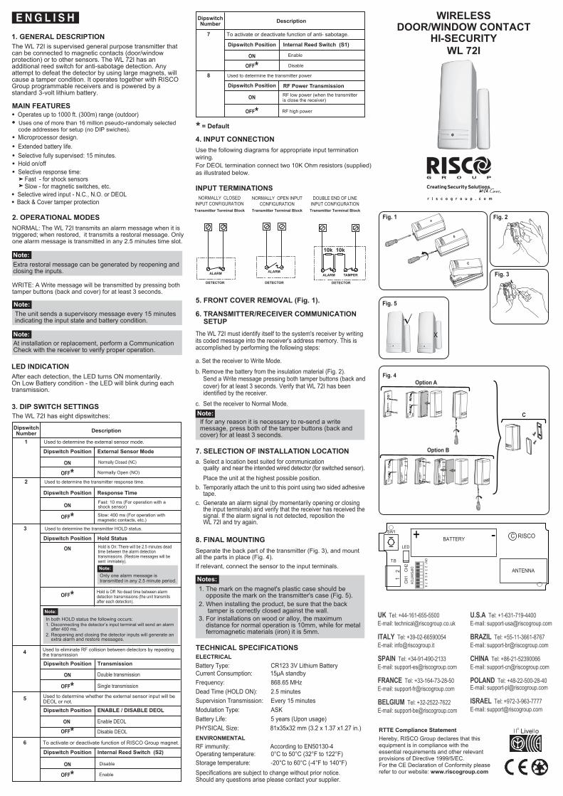
NORMALLY CLOSEDINPUT CONFIGURATIONTransmitter Terminal Block
NORMALLY OPEN INPUTCONFIGURATION
Transmitter Terminal Block
DOUBLE END OF LINEINPUT CONFIGURATIONTransmitter Terminal Block
7
Dipswitch Position Internal Reed Switch (S1)
OFF* Disable
EnableON
8
To activate or deactivate function of anti- sabotage.
4
ON Double transmission
Dipswitch Position Transmission
Used to eliminate RF collision between detectors by repeating the transmission
Single transmission
RF low power (when the transmitteris close the receiver)
1. GENERAL DESCRIPTION
MAIN FEATURES
● Uses one of more than 16 million pseudo-randomaly selected code addresses for setup (no DIP swiches).● Microprocessor design.● Extended battery life.● Selective fully supervised: 15 minutes.● Hold on/off● Selective response time:
Fast - for shock sensorsSlow - for magnetic switches, etc.
● Selective wired input - N.C., N.O. or DEOL
4. INPUT CONNECTIONUse the following diagrams for appropriate input terminationwiring.For DEOL termination connect two 10K Ohm resistors (supplied)as illustrated below.
INPUT TERMINATIONS
Place the unit at the highest possible position.b. Temporarily attach the unit to this point using two sided adhesive
tape.c. Generate an alarm signal (by momentarily opening or closing
the input terminals) and verify that the receiver has received thesignal. If the alarm signal is not detected, reposition theWL 72I and try again.
8. FINAL MOUNTINGSeparate the back part of the transmitter (Fig. 3), and mountall the parts in place (Fig. 4).If relevant, connect the sensor to the input terminals.
Notes:1. The mark on the magnet's plastic case should be opposite the mark on the transmitter's case (Fig. 5).2. When installing the product, be sure that the back tamper is correctly closed against the wall.3. For installations on wood or alloy, the maximum distance for normal operation is 10mm, while for metal ferromagnetic materials (iron) it is 5mm.
● Back & Cover tamper protection
2. OPERATIONAL MODESNORMAL: The WL 72I transmits an alarm message when it istriggered; when restored, it transmits a restoral message. Onlyone alarm message is transmitted in any 2.5 minutes time slot.
Note:Extra restoral message can be generated by reopening and closing the inputs.
WRITE: A Write message will be transmitted by pressing bothtamper buttons (back and cover) for at least 3 seconds.
Note:The unit sends a supervisory message every 15 minutesindicating the input state and battery condition.
Note:At installation or replacement, perform a CommunicationCheck with the receiver to verify proper operation.
LED INDICATIONAfter each detection, the LED turns ON momentarily.On Low Battery condition - the LED will blink during eachtransmission.
3. DIP SWITCH SETTINGSThe WL 72I has eight dipswitches:
6. TRANSMITTER/RECEIVER COMMUNICATION SETUPThe WL 72I must identify itself to the system's receiver by writing its coded message into the receiver's address memory. This isaccomplished by performing the following steps:
a. Set the receiver to Write Mode.b. Remove the battery from the insulation material (Fig. 2).
Send a Write message pressing both tamper buttons (back andcover) for at least 3 seconds. Verify that WL 72I has beenidentified by the receiver.
c. Set the receiver to Normal Mode.Note:If for any reason it is necessary to re-send a writemessage, press both of the tamper buttons (back andcover) for at least 3 seconds.
7. SELECTION OF INSTALLATION LOCATIONa. Select a location best suited for communication
quality and near the intended wired detector (for switched sensor).
5. FRONT COVER REMOVAL (Fig. 1).
TECHNICAL SPECIFICATIONSELECTRICALBattery Type: CR123 3V Lithium BatteryCurrent Consumption: 15µA standbyFrequency: 868.65 MHzDead Time (HOLD ON): 2.5 minutesSupervision Transmission: Every 15 minutesModulation Type: ASKBattery Life: 5 years (Upon usage)PHYSICAL Size: 81x35x32 mm (3.2 x 1.37 x1.27 in.)ENVIRONMENTALRF immunity: According to EN50130-4Operating temperature: 0°C to 50°C (32°F to 122°F)Storage temperature: -20°C to 60°C (-4°F to 140°F)Specifications are subject to change without prior notice.Should any questions arise please contact your supplier.
Dipswitch Position
ON
Hold Status
3
Dipswitch Position Response Time
2
Dipswitch Position External Sensor Mode
1
Normally Closed (NC)
Normally Open (NO)
DipswitchNumber Description
DipswitchNumber Description
Used to determine the external sensor mode.
Used to determine the transmitter response time.
Slow: 400 ms (For operation withmagnetic contacts, etc.)
Fast: 10 ms (For operation with ashock sensor)
Used to determine the transmitter HOLD status.
Hold is On: There will be 2.5 minutes deadtime between the alarm detectiontransmissions. (Restore messages will besent immiately).Note:Only one alarm message istransmitted in any 2.5 minute period.
Hold is Off: No dead time between alarmdetection transmissions (the unit transmitsafter each detection).
Note:In both HOLD status the following occurs:1. Disconnecting the detector’s input terminal will send an alarm
after 400 ms.2. Reopening and closing the detector inputs will generate an
extra alarm and restore messages.
OFF*ON
10k
ALARM TAMPER
10k
DETECTOR
ALARM
DETECTOR
ALARM
DETECTOR
6
5
ON Enable DEOL
OFF*
Dipswitch Position ENABLE / DISABLE DEOL
Used to determine whether the external sensor input will beDEOL or not.
Disable DEOL
ON
Dipswitch Position Internal Reed Switch (S2)
OFF*Disable
Enable
To activate or deactivate function of RISCO Group magnet.
* = Default
Used to determine the transmitter power
Dipswitch Position RF Power Transmission
ON
OFF* RF high power
ON
● Operates up to 1000 ft. (300m) range (outdoor)
Fig. 1
The WL 72I is supervised general purpose transmitter thatcan be connected to magnetic contacts (door/windowprotection) or to other sensors. The WL 72I has anadditional reed switch for anti-sabotage detection. Anyattempt to defeat the detector by using large magnets, willcause a tamper condition. It operates together with RISCOGroup programmable receivers and is powered by astandard 3-volt lithium battery.
ON
31
24
56
78
DIPSWITCH
SW1
LED
BATTERY
ANTENNA
+ - C RISCO
12
CH1
CH2
T.B
Fig. 2
Fig. 3
Fig. 5
WIRELESSDOOR/WINDOW CONTACT
HI-SECURITYWL 72I
Fig. 4Option A
Option B
C
RTTE Compliance StatementHereby, RISCO Group declares that this equipment is in compliance with the essential requirements and other relevant provisions of Directive 1999/5/EC.For the CE Declaration of Conformity please refer to our website: www.riscogroup.com
OFF*
OFF*
OFF*
UK Tel: +44-161-655-5500E-mail: [email protected]
ITALY Tel: +39-02-66590054E-mail: [email protected]
SPAIN Tel: +34-91-490-2133E-mail: [email protected]
FRANCE Tel: +33-164-73-28-50E-mail: [email protected]
BELGIUM Tel: +32-2522-7622E-mail: [email protected]
U.S.A Tel: +1-631-719-4400E-mail: [email protected]
BRAZIL Tel: +55-11-3661-8767E-mail: [email protected]
CHINA Tel: +86-21-52390066E-mail: [email protected]
POLAND Tel: +48-22-500-28-40E-mail: [email protected]
ISRAEL Tel: +972-3-963-7777E-mail: [email protected]

© RISCO Group 06/2010 5IN1303 C
ON
OFF*
1. DESCRIZIONE GENERALEWL 72I è un trasmettitore universale con supervisione chepuò essere connesso ai contatti magnetici (per protezione difinestre o porte) o ad altri sensori ed include anche un magneteche funziona tramite un “reed” integrato nell’unità.Questo trasmettitore ha un "reed" addizionale per rilevare tentatividi sabotaggio effettuati con dei grossi magneti. WL 72I è compatibile con i ricevitori programmabili RISCOGroup ed è alimentato con una batteria standard al litio da 3 V.Questo dispositivo è coperto da Certificazione IMQ - SISTEMIDI SICUREZZA 2° Livello di prestazione.
CARATTERISTICHE DI WL 72I
6. PROCEDURA DI MEMORIZZAZIONE DELTRASMETTITORE NELLA MEMORIA DELRICEVITOREWL 72I deve identificarsi al suo ricevitore scrivendo il suo Codicedi indirizzo univoco nella memoria del ricevitore.Procedere come segue:a. Impostare il ricevitore in modo memorizzazione trasmettitori (Modo WRITE)b. Rimuovere la batteria dal materiale isolante (Fig. 2). Premere i due tamper del trasmettitore per circa 3 secondi per inviare un messaggio di Indirizzo (Write). Verificate che WL 72I sia stato identificato dal ricevitore.c. Impostare ora il ricevitore nel modo normale di funzionamento.
Nota:Se in caso fosse necessario rinviare un messaggio"Write", premere ancora il tamper per circa 3 secondi,sia quello antirimozione che quello antiapertura.
7. SCELTA DELLA POSIZIONE DI INSTALLAZIONEa. Scegliere una posizione ottimale per garantire una buona
comunicazione radio, in prossimità dell’eventuale rivelatore ocontatto che andrà cablato al trasmettitore tramite il suo ingressoesterno (se richiesto). Installate il dispositivo il più in alto possibile.
b. Fissare temporaneamente il dispositivo con del biadesivo.
c. Generare un segnale di allarme (aprendo o chiudendo il contatto del WL 72I) e verificare che il ricevitore abbia ricevuto il segnale. Se il segnale non è stato ricevuto, riposizionare il trasmettitore WL 72I e riprovare.
8. MONTAGGIO FINALESeparare la parte posteriore del trasmettitore (Fig. 3), fissare ilsupporto alla parete o all’infisso e infine rimontare il trasmettitorealla base (Fig. 4).Terminare l’installazione collegando il contatto o sensore all’ingressoesterno dell'unità e/ o posizionare il magnete fornito con l’unità.
Nota:Il marchio sulla plastica del contatto magnetico deveessere posizionato dal lato opposto rispetto al marchioposto sul contenitore del trasmettitore (Fig. 5).Per il corretto funzionamento del tamper antirimozioneinstallare una vite a testa piatta nel muro incorrispondenza della molla di chiusura del tamperantirimozione.Per installazioni su legno e alluminio la distanza massimadi funzionamento del magnete è 10mm, per installazionisul metallo la distanza è di 5mm.
SPECIFICHE TECNICHEELETRICHEModello Batteria: CR123 3V al Litio Assorbimento in Corrente: 15µA a riposoFrequenza: 868.65 MHzBlocco Trasmissioni: 2.5 minuti (se abilitato)Trasmissione Supervisione: Ogni 15 minutiTipo di Modulazione: ASK Autonomia Batteria: 5 anni (dipende dall'utilizzo)FISICHEDimensioni: 81 x 35 x 32 mmAMBIENTALI Immunità RF: Conforme alla normativa EN50130-4Temp. di funzionamento: da 0°C a 50°CTemp. di Stoccaggio: da -20°C a 60°C
Le informazioni e le caratteristiche tecniche riportate in questodocumento sono soggette a variazione senza l'obblico di preavviso.Per qualsiasi informazione contattare il proprio distributore.
Veloce: per sensori inerziali Lenta: per contatti magnetici
2. MODI DI FUNZIONAMENTONORMALE: Il Nova 72 trasmette un MESSAGGIO di ALLARME quando attivato e trasmette un MESSAGGIO di RIPRISTINO quandoviene ripristinato. Solamente un MESSAGGIO di ALLARME vienetrasmesso nell’arco di tempo di 2.5 minuti (con la funzione BloccoTrasmissioni abilitata).
Nota:Ulteriori messaggi di ripristino possono essere attivatiaprendo e richiudendo gli ingressi del trasmettitore.
WRITE: Un messaggio “WRITE” di trasmissione indirizzo verràtrasmesso se il tasto del Tamper (sia apertura che rimozione) vienepremuto per almeno 3 secondi.
4. COLLEGAMENTO DELL'INGRESSO ESTERNOUsare gli schemi che seguono per il collegamento del dispositivoesterno all'ingresso del trasmettitore.Per il collegamento DEOL in doppio bilanciamento resistivocollegare due resistenze da 10K Ohm (fornite) come di seguitoillustrato.
Nota:per la certificazione IMQ - SISTEMI DI SICUREZZA
1. La configurazione Risposta veloce con tempo di apertura a 10ms. è applicabile solo ai rivelatori inerziali.
2. L'utilizzo dell'ingresso esterno del trasmettitore è subordinato allaconfigurazione DEOL con doppio bilanciamento resistivo. L'ingressoesterno utilizzato in configurazione Normalmente Aperto oNormalmente Chiuso fanno decadere la certificazione IMQ -Sistemi di Sicurezza.
3. L'ingresso esterno va utilizzato collegando un dispositivo checertificato IMQ - SISTEMI DI SICUREZZA al 2° livello diprestazione, pena il decadimento della certificazione IMQ.
4. La funzione di sabotaggio Contatto Reed interno deve essere abilitato o la certificazione IMQ - SISTEMI DI SICUREZZA decade dal 2° al 1° Livello di prestazione.
5. RIMOZIONE DEL CONTENITORE (Fig. 1)
Nota:Il dispositivo invia un messaggio di supervisione ogni 15minuti, per indicare lo stato degli ingressi e la condizionedella batteria.
Nota:All’installazione dell’unità o alla sostituzione della batteriaeffettuare sempre un test di comunicazione radio con ilricevitore al fine di verificare il buon funzionamento deltrasmettitore.
INDICATORE LED:Dopo ogni variazione dell’ingresso del trasmettitore, il LED si accendemomentaneamente. Se la batteria è scarica, il LED lampeggerà per3 volte durante ogni trasmissione.
3. PREDISPOSIZIONE DEI MICROINTERRUTTORIIl trasmettitore WL 72I è dotato di un banco di 8 microinterruttoriche predispongono il tramettitore nei diversi modi di funzionamentodi seguito riportati.
4
N. Micro-interrut. Descrizione
Note:In entrambe le modalità di blocco trasmissioni:1. Scollegando il dispositivo collegato all'ingresso l'unità trasmetterà un allarme dopo 400 ms.2. Aprendo nuovamente e richiudendo l'ingresso l'unità trasmetterà un ulteriore segnale di ripristino.
5
ON Trasmissione doppia
OFF*
Posizione Microint. Trasmissione
Ripetizione trasmissione per sopperire alle collisioni di segnaleRF. Utilizzare solo se necessario per gli ambienti dove sono presenti più trasmettitori che trasmettono simultaneamente.
Trasmissione singola
ON DEOL Abilitato
OFF*
Posizione Microint. Doppio Bilanciamento DEOL
Configura l'ingresso esterno con o senza doppiobilanciamento EOL.
DEOL Disabilitato6
7
ON
Posizione Microint. Contatto Reed interno (S2)
OFF*Disabilitato
Abilitato
Posizione Microint. Reed Sabotaggio interno (S1)
OFF* Disabilitato
AbilitatoON
8
Attiva o Esclude il Contatto Reed interno all'unità
Attiva o Esclude il controllo sabotaggio sul Contatto Reedinterno.
* = Configurazione di Default
Posizione Microint.
OFF*
ON
Blocco Trasmissioni3
Posizione Microint. Tempo di Apertura Ingresso
2
Posizione Microint.
OFF*ON
Modalità ingresso Esterno
1
Normalmente Chiuso (NC)
Normalmente Aperto (NO)
N. Micro-interrut. Descrizione
Utilizzato per configurare l'ingresso esterno NC o NO .
Imposta il tempo di apertura dell'ingresso esterno.
Normale: 400 ms (Per il controllodi contatti magnetici, etc..)
Veloce: 10 ms (Per il controllodi sensori sismici)
Modifica lo stato della funzione Blocco Trasmissioni.
Blocco Attivo: Dopo una trasmissionel'unità si inibisce per 2.5 minuti. (I ripristini verranno comunque sempre trasmessi).Nota:Solo un messaggio di allarme vienetrasmesso ogni 2.5 minuti.
Blocco Disattivato: Non vieneapplicato alcun blocco alletrasmissioni. L'unità trasmettesempre ogni qualvolta vieneattivata.
Posizione Microint.Usato per determinare la potenza RF del trasmettitore.
Potenza RF
Potenza RF alta
Potenza RF bassa
10k
TAMPER
10k
COLLEGAMENTO INGRESSOIN DOPPIO BILANCIAMENTO
Morsettiera Trasmettitore
RIVELATORERIVELATORERIVELATORE
ALLARME
Morsettiera Trasmettitore
COLLEGAMENTO INGRESSONORMALMENTE APERTO
COLLEGAMENTO INGRESSONORMALMENTE CHIUSO
ALLARME
Morsettiera Trasmettitore
OFF*ON
● Ha una portata radio di 300 metri in campo aperto Utilizza un indirizzo univoco selezionato automaticamente tra più di 16 milioni di indirizzi (nessun banco di microinterruttori)● Tecnologia a microprocessore● Batteria a lunga durata● Completamente supervisionato● Tempo di risposta selezionabile come:
● Ingresso esterno programmabile per contatti N. C. o N. O. o doppio bilanciamento resistivo● Protezione antirimozione e antiapertura
ALLARME
RISCO Group LIMITED WARRANTYRISCO Group and its subsidiaries and af filiates ("Seller")warrants its products to be free from defects in materials and workmanship under normal use for 24 months from the date of production. Because Seller does not install or connect the product and because the product may be used in conjunction with products not manufactured by the Seller, Seller can not guarantee the performance of the security system which uses this product. Sellers obligation and liability under this warranty is expressly limited to repairing and replacing,at Sellers option, within a reasonable time after the date of delivery, any product not meeting the specifications. Seller makes no other warranty, expressed or implied, and makes no warranty of merchantability or of fitness for any particular purpose.In no case shall seller be liable for any consequential or incidental damages for breach of this or any other warranty, expressed or implied, or upon any other basis of liability whatsoever. Sellers obligation under this warranty shall not include any transportation charges or costs of installation or any liability for direct, indirect, or consequential damages or delay Seller does not represent that its product may not be compromised or circumvented; that the product will prevent any personal; injury or property loss by burglary, robbery, fire or otherwise; or that the product will in all cases provide adequate warning or protection. Buyer understands that a properly installed and maintained alarm may only reduce the risk of burglary, robbery or fire without warning, but is not insurance or a guaranty that such will not occur or that there will be no personal injury or property loss as a result. Consequently seller shall have no liability for any personal injury, property damage or loss based on a claim that the product fails to give warning. However, if seller is held liable, whether directly or indirectly, for any loss or damage arising from under this limited warranty or otherwise, regardless of cause or origin, sellers maximum liability shall not in any case exceed the purchase price of the product, which shall be complete and exclusive remedy against seller. No employee or representative of Seller is authorized to change this warranty in any way or grant any other warranty.
NOTE: This product should be tested at least once a week.