Embed Size (px)
Citation preview
BANDYOPADHYAY et al: WIRELESS INFORMATION AND SAFETY SYSTEM FOR MINES 107Journal of Scientific & Industrial Research
Vol. 68, February 2009, pp.107-117
*Author for correspondence
Telefax: 0326-2296045, E-mail: [email protected]
Wireless information and safety system for mines
L K Bandyopadhyay1*, S K Chaulya1, P K Mishra1, A Choure1 and B M Baveja2
1Central Institute of Mining and Fuel Research (CIMFR), Dhanbad 826 001, India
2Department of Information Technology, Ministry of Communication and Information Technology,
New Delhi 110 003, India
Received 16 May 2008; revised 21 November 2008; accepted 25 November 2008
This study presents a wireless information and safety system for mines developed by CIMFR, Dhanbad. System consists
of hardware devices and application software. Hardware module is ZigBee-compliant active radio frequency identification
(RFID) devices/ transceivers, which can be programmed to act as end device (tag), router or coordinator that enables them to
form an IEEE 802.15.4-based mesh network. It uses a unified wireless mesh-networking infrastructure to locate, trace and
manage mobile assets and people as well as monitor different environmental conditions using sensors. Another core module is
wireless sensor network (WSN) software, which is developed for tracking of underground miners and moveable equipment by
wireless sensor networking in mines. Software is especially designed for tracking of miners and vehicles, route tracking in
opencast mines, preventing fatal accidents and vehicle collisions, environmental monitoring, observing miners’ unsafe practice,
sending alert message, and preparing computerized miners’ duty hours record.
Keywords: Mining, Tracking and monitoring, Wireless sensor network, ZigBee devices
Introduction
In case of disaster in an underground mine, it is very
difficult for mine management to identify actual person
trapped, their number and exact location. Therefore,
identification and coding of miners is a vital need for
underground mine management in case of disaster as
well as normal operating conditions. Mining industry
is generally capital intensive; cost of maintenance (35%
of operating cost of system) at mechanized mines goes
as high as 50-60% when both direct and indirect costs
are taken into account1. Sometimes, it constitutes 30%
of total production cost. In today’s globally competitive
market scenario, efforts to reduce production cost have
awaken mining industry for automation and optimum
utilization of equipment by increasing its availability
and performance2,3. This study presents a wireless
information & safety system for mines (WISSM),
developed by CIMFR, Dhanbad.
Wireless Information & Safety System for Mines
(WISSM)
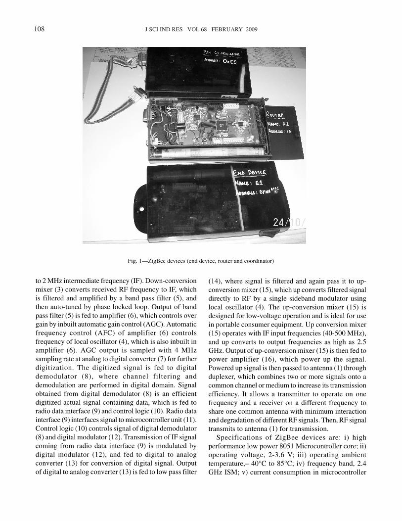
Core system component, ZigBee-compliant active
RFID device, can be programmed to act as tag (end
device), router or coordinator (Fig. 1) that enables them
to form an IEEE 802.15.4-based mesh network4. It uses a
unified wireless mesh-networking infrastructure to locate,
trace and manage mobile assets and people as well as
monitor different environmental conditions using
sensors5-7. ZigBee devices have numerous advantages8-11
as follows: i) unlicensed 2.4 GHz industrial, scientific
and medical (ISM) band; ii) ultra low power (ideal for
battery operated system) requirement; iii) operates for
years on inexpensive batteries; iv) large number of nodes/
sensors; v) reliable and secure links between network
nodes; vi) easy deployment and configuration; vii) low
cost system; viii) very fast transition time; ix) digital
battery monitor facility; and x) smaller in size (system
on chip).
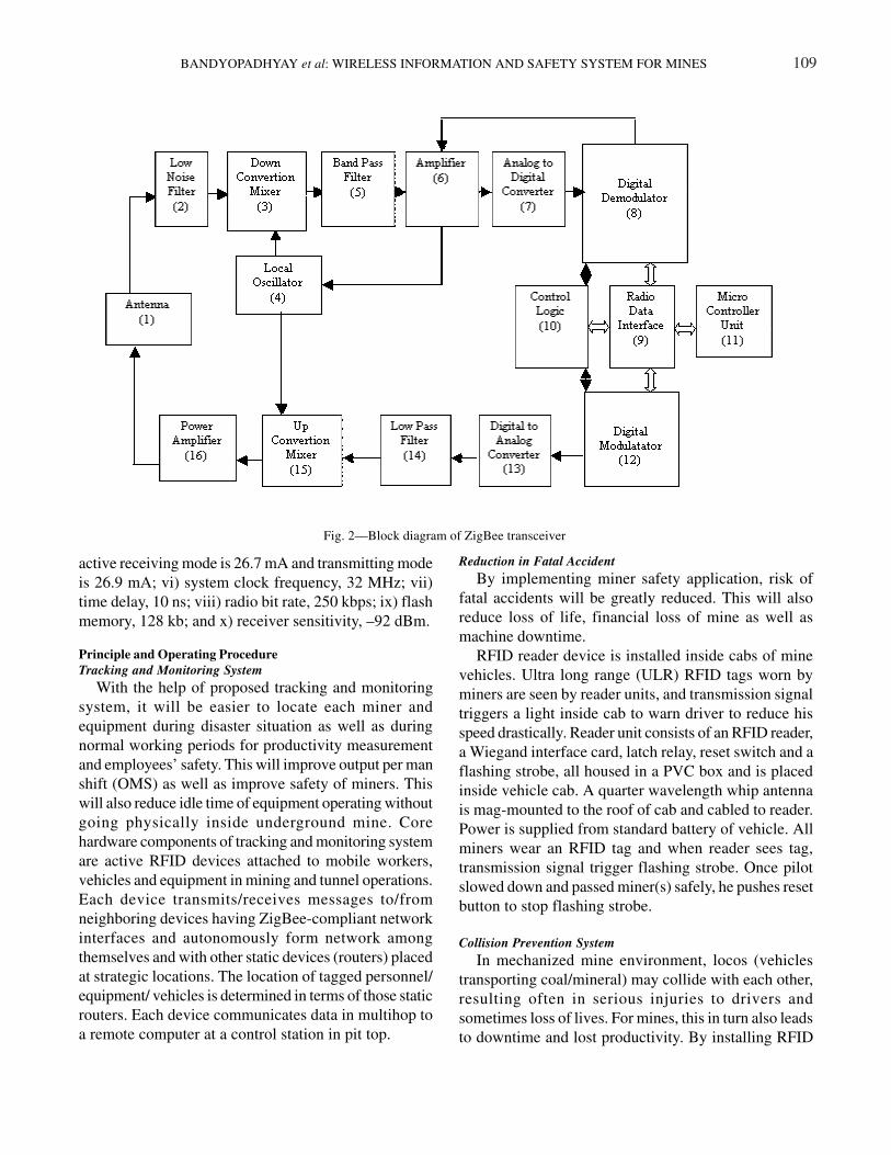
In ZigBee transceiver (Fig. 2), incoming 2.4 GHz RF
signal is picked up by antenna (1) and pass to low noise
filter (2) through duplexer. Low noise filter (2) eliminates
DC offset and noise problem, and amplifies radio
frequency (RF) signal from antenna to a suitable level
before feeding to down–conversion mixer (3), which
mixes amplified signal with a high frequency signal
generated by local oscillator (4). Output of down-
conversion mixer (3) is then fed to a band pass filter (5),
and signal thus obtained is down converted in quardrature
108 J SCI IND RES VOL 68 FEBRUARY 2009
to 2 MHz intermediate frequency (IF). Down-conversion
mixer (3) converts received RF frequency to IF, which
is filtered and amplified by a band pass filter (5), and
then auto-tuned by phase locked loop. Output of band
pass filter (5) is fed to amplifier (6), which controls over
gain by inbuilt automatic gain control (AGC). Automatic
frequency control (AFC) of amplifier (6) controls
frequency of local oscillator (4), which is also inbuilt in
amplifier (6). AGC output is sampled with 4 MHz
sampling rate at analog to digital converter (7) for further
digitization. The digitized signal is fed to digital
demodulator (8), where channel filtering and
demodulation are performed in digital domain. Signal
obtained from digital demodulator (8) is an efficient
digitized actual signal containing data, which is fed to
radio data interface (9) and control logic (10). Radio data
interface (9) interfaces signal to microcontroller unit (11).
Control logic (10) controls signal of digital demodulator
(8) and digital modulator (12). Transmission of IF signal
coming from radio data interface (9) is modulated by
digital modulator (12), and fed to digital to analog
converter (13) for conversion of digital signal. Output
of digital to analog converter (13) is fed to low pass filter
(14), where signal is filtered and again pass it to up-
conversion mixer (15), which up converts filtered signal
directly to RF by a single sideband modulator using
local oscillator (4). The up-conversion mixer (15) is
designed for low-voltage operation and is ideal for use
in portable consumer equipment. Up conversion mixer
(15) operates with IF input frequencies (40-500 MHz),
and up converts to output frequencies as high as 2.5
GHz. Output of up-conversion mixer (15) is then fed to
power amplifier (16), which power up the signal.
Powered up signal is then passed to antenna (1) through
duplexer, which combines two or more signals onto a
common channel or medium to increase its transmission
efficiency. It allows a transmitter to operate on one
frequency and a receiver on a different frequency to
share one common antenna with minimum interaction
and degradation of different RF signals. Then, RF signal
transmits to antenna (1) for transmission.
Specifications of ZigBee devices are: i) high
performance low power 8051 Microcontroller core; ii)
operating voltage, 2-3.6 V; iii) operating ambient
temperature,– 40°C to 85°C; iv) frequency band, 2.4
GHz ISM; v) current consumption in microcontroller
Fig. 1—ZigBee devices (end device, router and coordinator)
BANDYOPADHYAY et al: WIRELESS INFORMATION AND SAFETY SYSTEM FOR MINES 109
active receiving mode is 26.7 mA and transmitting mode
is 26.9 mA; vi) system clock frequency, 32 MHz; vii)
time delay, 10 ns; viii) radio bit rate, 250 kbps; ix) flash
memory, 128 kb; and x) receiver sensitivity, –92 dBm.
Principle and Operating Procedure
Tracking and Monitoring System
With the help of proposed tracking and monitoring
system, it will be easier to locate each miner and
equipment during disaster situation as well as during
normal working periods for productivity measurement
and employees’ safety. This will improve output per man
shift (OMS) as well as improve safety of miners. This
will also reduce idle time of equipment operating without
going physically inside underground mine. Core
hardware components of tracking and monitoring system
are active RFID devices attached to mobile workers,
vehicles and equipment in mining and tunnel operations.
Each device transmits/receives messages to/from
neighboring devices having ZigBee-compliant network
interfaces and autonomously form network among
themselves and with other static devices (routers) placed
at strategic locations. The location of tagged personnel/
equipment/ vehicles is determined in terms of those static
routers. Each device communicates data in multihop to
a remote computer at a control station in pit top.
Reduction in Fatal Accident
By implementing miner safety application, risk of
fatal accidents will be greatly reduced. This will also
reduce loss of life, financial loss of mine as well as
machine downtime.
RFID reader device is installed inside cabs of mine
vehicles. Ultra long range (ULR) RFID tags worn by
miners are seen by reader units, and transmission signal
triggers a light inside cab to warn driver to reduce his
speed drastically. Reader unit consists of an RFID reader,
a Wiegand interface card, latch relay, reset switch and a
flashing strobe, all housed in a PVC box and is placed
inside vehicle cab. A quarter wavelength whip antenna
is mag-mounted to the roof of cab and cabled to reader.
Power is supplied from standard battery of vehicle. All
miners wear an RFID tag and when reader sees tag,
transmission signal trigger flashing strobe. Once pilot
slowed down and passed miner(s) safely, he pushes reset
button to stop flashing strobe.
Collision Prevention System
In mechanized mine environment, locos (vehicles
transporting coal/mineral) may collide with each other,
resulting often in serious injuries to drivers and
sometimes loss of lives. For mines, this in turn also leads
to downtime and lost productivity. By installing RFID
Fig. 2—Block diagram of ZigBee transceiver
110 J SCI IND RES VOL 68 FEBRUARY 2009
collision prevention system, risk of accidents and
machine downtime will be greatly reduced and
productivity improved. In ZigBee -compliant RFID
collision prevention system, each loco is fitted with two
asset tags (one each at front and back) and an RFID
reader unit, consisting of an ULR RFID reader, a
Wiegand interface, antenna, and a timer relay. Reader
unit is interfaced with loco controller to control speed
(average, 40 km/h). When reader detects an asset tag
signal from another loco in the vicinity at a range of
approx 50 m, power supply from power supply unit
(PSU) to controller is reduced (50%), thus automatically
reducing speed, at which loco is traveling. This in itself
is also a warning to loco driver that another loco is
approaching or in the same area. When RFID tag is no
longer seen by reader, power supply is automatically
increased (100%) and activates controller to run at full
speed again.
Efficiency and Productivity Monitoring System
RFID technology and devices can be used effectively
for monitoring and measuring productivity through an
application that allows for identification of location and
tracking of movement of a mine’s fleet. By using this
automatic (and accurate) means of collecting data over
a period of time, it is possible to determine how
efficiently and productively mine site is being managed.
It is also an indication of whether mines assets (fleet)
are managed cost-effectively. In other words, to optimize
productivity and asset management, mine management
may decide that it needs to either increase or decrease
number of vehicles and/or number of hours worked per
shift. Costs can also be calculated more accurately and
measured against productivity of a particular mine site.
This will also improve OMS, which leads to efficient
productivity.
At an opencast mine, each vehicle is fitted with a Data
Collection RFID unit consisting of: a) RFID reader; b)
tag buffer; c) 24 V to 12 V step-down converter; d) 9-
pin RS-232 serial connector; and e) antenna. RFID tags
are mounted at specific locations around mine site to
mark routes followed by vehicles. When a vehicle fitted
with data collection unit moves past a ‘route marker’,
first and last transmission from tag is recorded in
database of the unit. Data is downloaded and analyzed
to determine each vehicle route. As all records are time
stamped, it is also possible to determine time taken for
each vehicle to complete the route. At present system
based on GPS technology12,13 is popular for tracking and
monitoring of vehicles in opencast mines. But it is costly
and not specifically developed for opencast mine
applications like analysis of shovel-dumper performance.
Even application software of developed technologies is
different from GPS system, which specifically
incorporates module for optimizing shovel-dumper
performance.
Monitoring Miners’ Unsafe Practice and Warning System
Generally, underground miners are unknowingly
going to the danger area, like, unsupported area where
chances of roof fall are frequent, near blasting area,
gaseous area etc. These unsafe practices cause several
accidents in underground mine. Therefore, a continuous
monitoring and warning system must be implemented
in the underground mines to avoid such common
accidents. People working in the underground mine will
be safe and an audio-visual warning will be provided
while particular miner entering in an unsafe area. Thus
frequent accidents will be minimized.
Miners are continuously tracked using RFID tags
provided to each worker. Unsafe practice of concerned
person is analyzed by computerized software, and based
on the information, mine management gives warning to
defaulter. Further, an audio-visual warning system is
incorporated in each tag to automatically warn particular
miner entering into unsafe areas.
Software
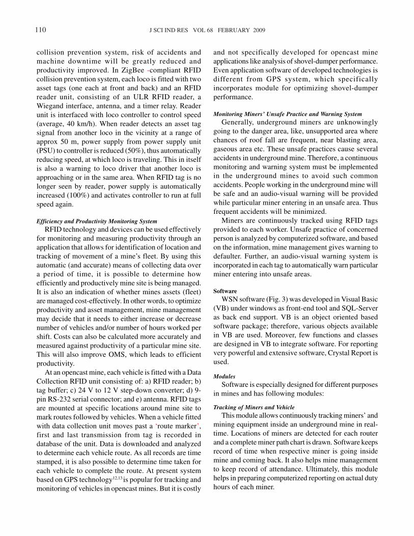
WSN software (Fig. 3) was developed in Visual Basic
(VB) under windows as front-end tool and SQL-Server
as back end support. VB is an object oriented based
software package; therefore, various objects available
in VB are used. Moreover, few functions and classes
are designed in VB to integrate software. For reporting
very powerful and extensive software, Crystal Report is
used.
Modules
Software is especially designed for different purposes
in mines and has following modules:
Tracking of Miners and Vehicle
This module allows continuously tracking miners’ and
mining equipment inside an underground mine in real-
time. Locations of miners are detected for each router
and a complete miner path chart is drawn. Software keeps
record of time when respective miner is going inside
mine and coming back. It also helps mine management
to keep record of attendance. Ultimately, this module
helps in preparing computerized reporting on actual duty
hours of each miner.
BANDYOPADHYAY et al: WIRELESS INFORMATION AND SAFETY SYSTEM FOR MINES 111
Fig. 3—WSN software layout
112 J SCI IND RES VOL 68 FEBRUARY 2009
Route Tracking in Opencast Mines
This module allows tracking a dumper movement in
opencast mine. Locations of dumper are detected for
each router and a complete dumpers path chart is drawn.
Software keeps record of time when respective vehicle
is going inside mine and coming back. It also helps mine
management to keep record of duration of time.
Ultimately, this module helps in preparing computerized
reporting on actual duty hours of each dumper. This
module can also be used for optimizing shovel-dumper
performance and deploying optimum number of dumpers
for a particular opencast mine.
Preventing Fatal Accidents
This module allows preventing fatal accident in
underground mine by transmitting warning signal to
miners and loco drivers. Software detects position and
path of miner and moving loco, and automatically warns
miner and loco driver when miner and loco are
approaching nearer in same path.
Preventing Vehicle Collisions
This module allows monitoring locos’ position inside
an underground mine and transmitting warning signal
to vehicle drivers approaching nearer. Software detects
position and path of moving vehicle to/fro then
automatically warns driver after sensing vehicle reader
tag, if both vehicles are in same path and approaching
nearer.
Environmental Monitoring
This module allows wirelessly monitoring mine’s
environmental conditions using appropriate sensors.
Software automatically collects data through coordinator
of a router to which a sensor is coupled. On-line
environmental data and graph can be seen on monitor.
System gives warning when concentration of a particular
gas reaches its permissible limit.
Monitoring Miners’ Unsafe Practice
This module monitors miners’ unsafe practices and
generates warning. System automatically detects router,
which is placed in unsafe area. When any miner
approaches near unsafe area router, then system warns
the particular miner by audio-visual alarm and system
automatically starts beeping at surface computer. This
can help in ensuring miners safety and generates a log
file for keeping record with a particular date and time.
Sending Alert Message
This module generates alarm messages on user-
defined conditions. Different coded messages can also
be sent to respective miner as and when required.
Operating Mode
Software operates on-line and off-line. In on-line
(real-time) mode, CPU is connected to coordinator by a
serial port, and read periodic tag’s data through various
routers by multi-hoping technique. Coordinator receives
signal from different routers, which are placed in
strategic locations. Active RFID devices are attached to
underground miners. Each device can transmit/receive
signal to/from neighbouring devices. Devices with
ZigBee-complaint network interfaces can autonomously
form network among themselves and with other static
devices. The locations of tagged personnel are displayed
numerically or graphically on the system and data is
automatically saved in a database file. In this mode of
operation, location of miner is detected for each router
and draws a complete miner path chart as per request.
Software keeps record of time when respective miner is
going inside mine and coming back. It also helps mine
management to keep record of attendance. Ultimately,
this software helps in preparing computerized reporting
on actual duty hours of each miner.
In off-line mode, one can display stored data by simply
selecting file of required date. Graphical location of
particular miner can also be displayed on screen. In both
operating modes, software supports hard copy printing
of data (numerical or graphical as desired).
Administrator can change software configurations, like
working area of mine plan, unit of scale, router locations,
router status and different essential parameters. Enough
security has been maintained using password.
Requirement
Minimum requirements for running WSN software
are: i) hardware requirements include CPU – Pentium
IV, HDD – 40 GB (free), RAM – 512 MB, colour monitor
resolution – 1024 × 768, 32 bit colour quality, one free
serial communication port, and serial data cable; and ii)
software requirements include operating system –
Windows NT/XP/2000/2003, SQL server 2000, and
Crystal Report 8.5.
System Installation Procedure
Installation procedures for underground mine with
shaft entrance and with incline entrance (Fig. 4) and
opencast mine (Fig 5) are depicted. ZigBee transceivers/
BANDYOPADHYAY et al: WIRELESS INFORMATION AND SAFETY SYSTEM FOR MINES 113
PC1 C1
R1
R8 R9 R2 R5 R6 R7
R12 R11
R4
R3
R14 R13
R15 R16 R17 R18 R19
E1 E2
E3
E6 E7 E8
E9
E5 E4
R10
U1
S1
CR1
SH
G1
G2
G3
C2 PC2
R27
R28
R29
R23
R24
R25
R26
R33 R34 R31 R32 R30
E10
E12 E13 E11
R21 R22 S2
U2
CR2
R20
I 1 I 2
G4
A)
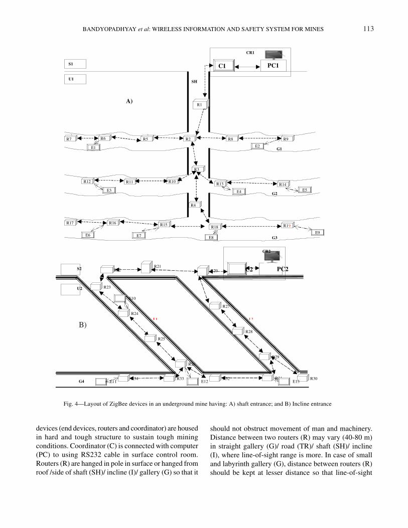
Fig. 4—Layout of ZigBee devices in an underground mine having: A) shaft entrance; and B) Incline entrance
B)
devices (end devices, routers and coordinator) are housed
in hard and tough structure to sustain tough mining
conditions. Coordinator (C) is connected with computer
(PC) to using RS232 cable in surface control room.
Routers (R) are hanged in pole in surface or hanged from
roof /side of shaft (SH)/ incline (I)/ gallery (G) so that it
should not obstruct movement of man and machinery.
Distance between two routers (R) may vary (40-80 m)
in straight gallery (G)/ road (TR)/ shaft (SH)/ incline
(I), where line-of-sight range is more. In case of small
and labyrinth gallery (G), distance between routers (R)
should be kept at lesser distance so that line-of-sight
114 J SCI IND RES VOL 68 FEBRUARY 2009
distance is maintained among routers (R), which should
be placed in such a way that in case of disaster in a
particular portion of mine, communication can be
established by alternative routes automatically.
Following above guidelines, routers (R) are placed on
required portion of mine, where monitoring and tracking
of miners and moveable equipment are needed. These
routers (R) form wireless network with coordinator (C).
Required environmental monitoring sensors are attached
to particular routers, where gas monitoring is essential.
End devices (E) are assigned to miners and moveable
equipment. End devices (E) transmit signal to respective
routers (R), which receives signal and transmit to next
routers (R) and subsequently data is transmitted to
coordinator (C) through intermediate routers by multi-
hop transmission mechanism. Finally, coordinator (C)
sends data to computer (PC). Same data is processed,
analyzed and stored in computer (PC) using WSN
software, which controls and commands all operations
performed by total network.
Wireless sensor network (Fig. 4A) in an underground
mine having shaft entrance consists of a personnel
computer (PC1), coordinator (C1), router (R1 to R19)
and end devices (E1 to E9). PC1 is connected to C1
using RS232 cable in surface (S1) control room (CR1).
Routers (R1 to R4) are wirelessly connected with C1 at
a distance 60 m apart in an underground (U1) shaft (SH).
Routers (R5 to R7) placed in left and routers (R8 to R9)
placed in right side of first galley (G1), at 50 m apart are
wirelessly connected to router R2. End devices (E1 and
E2) attached with miners/moveable equipment are
wirelessly communicated with routers R6 and R9
respectively. Routers (R10 to R12) placed in left and
routers (R13 to R14) placed in right side of second galley
(G2), are wirelessly connected to router R3. End devices
(E3, E4 and E5) attached with miners/moveable
equipment is wirelessly communicated with routers R12,
R13 and R14, respectively. Routers (R15 to R17) placed
in left and routers (R18 to R19) placed in right side of
third galley (G3), are wirelessly connected to router R4.
End devices (E6 to E9) attached with miners/moveable
equipment are wirelessly communicated with routers
R16, R15, R18 and R19, respectively.
Wireless sensor network in an underground mine
having incline entrance (Fig. 4B) consists of a personnel
computer (PC2), coordinator (C2), router (R20 to R34)
and end devices (E10 to E13). PC2 is connected to C2
using RS232 cable in surface (S2) control room (CR2).
Routers (R20, R21 and R22) are wirelessly connected
to C2 at 80 m apart in surface (S). Routers (R23 to R26)
placed in intake incline (I1) at 50 m are wirelessly
connected to router R22. Routers (R27 to R29) placed
in return incline (I2) are wirelessly connected to R20.
Routers (R30 to R34) placed in gallery (G4) at 50 m are
wirelessly connected to R26 and R29. End device (E10
to E13) fitted with miners/moveable equipment is
wirelessly communicated with routers R24, R34, R26
and R31, respectively.
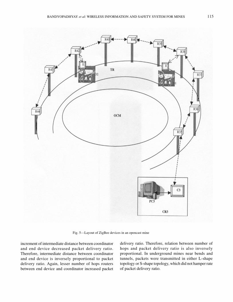
Wireless sensor network in an opencast mine (Fig. 5)
consists of a personnel computer (PC3), coordinator
(C3), router (R35 to R44) and end devices (E14 and
E15). PC3 is connected to C3 using RS232 cable in
surface control room (CR3). Routers (R35 to R44)
placed along transport road (TR) of an opencast mine
(OCM) at an interval of around 80 m distance are
wirelessly connected with said coordinator (C3). End
devices (E14 and E15) fitted with dumpers (D1 and D2)
are wirelessly communicated with said routers (R38 and
R42) routers, respectively.
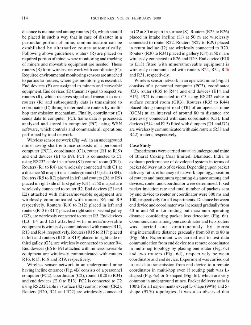
Case Study
Experiments were carried out at an underground mine
of Bharat Coking Coal limited, Dhanbad, India to
evaluate performance of developed system in terms of
packet delivery ratio of devices. Depending upon packet
delivery ratio, efficiency of network topology, position
of routers and maximum operating distance among end
devices, router and coordinator were determined. Fixed
packet injection rate and total number of packets sent
by end device to router or coordinator were 300 ms and
100, respectively for all experiments. Distance between
end device and coordinator was increased gradually from
40 m and 60 m for finding out maximum operating
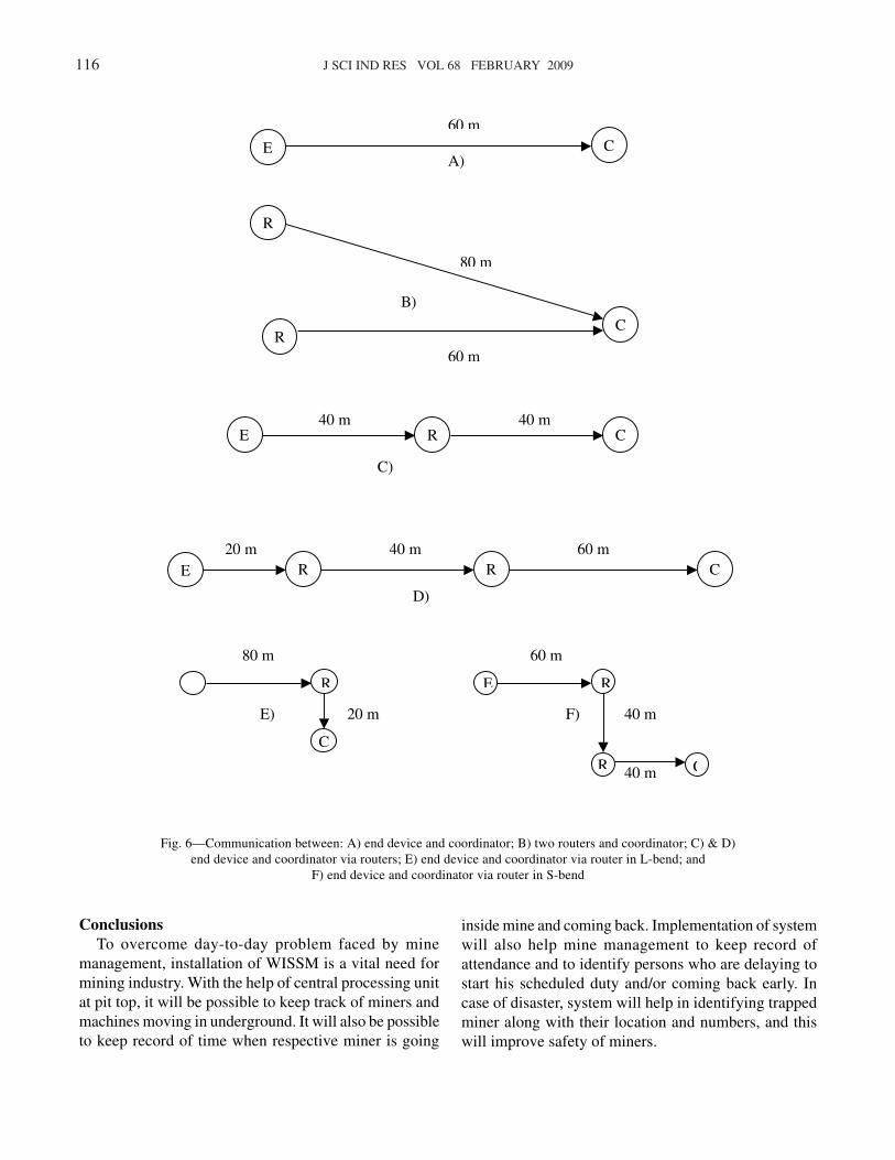
distance considering packet loss detection (Fig. 6a).
Communication among one coordinator and two routers
was carried out simultaneously by increa
sing intermediate distance gradually from 60 m to 80 m
(Fig. 6b). Experiment was carried out to test data
communication from end device to a remote coordinator
in multi-hop topology by placing one router (Fig. 6c)
and two routers (Fig. 6d), respectively between
coordinator and end device. Experiment was carried out
to test data transmission from end device to a remote
coordinator in multi-hop even if routing path was L-
shaped (Fig. 6e) or S-shaped (Fig. 6f), which are very
common in underground mines. Packet delivery ratio is
100% for all experiments except L-shape (99%) and S-
shape (97%) topologies. It was also observed that
BANDYOPADHYAY et al: WIRELESS INFORMATION AND SAFETY SYSTEM FOR MINES 115
increment of intermediate distance between coordinator
and end device decreased packet delivery ratio.
Therefore, intermediate distance between coordinator
and end device is inversely proportional to packet
delivery ratio. Again, lesser number of hops routers
between end device and coordinator increased packet
delivery ratio. Therefore, relation between number of
hops and packet delivery ratio is also inversely
proportional. In underground mines near bends and
tunnels, packets were transmitted in either L-shape
topology or S-shape topology, which did not hamper rate
of packet delivery ratio.
Fig. 5—Layout of ZigBee devices in an opencast mine
116 J SCI IND RES VOL 68 FEBRUARY 2009
Conclusions
To overcome day-to-day problem faced by mine
management, installation of WISSM is a vital need for
mining industry. With the help of central processing unit
at pit top, it will be possible to keep track of miners and
machines moving in underground. It will also be possible
to keep record of time when respective miner is going
inside mine and coming back. Implementation of system
will also help mine management to keep record of
attendance and to identify persons who are delaying to
start his scheduled duty and/or coming back early. In
case of disaster, system will help in identifying trapped
miner along with their location and numbers, and this
will improve safety of miners.
E C
60 m
A)
R
R C
80 m
60 m
B)
E R C 40 m 40 m
C)
E R C R
D)
60 m 40 m 20 m
E
60 m
40 m
E R
R 40 m C
F)
80 m
20 m
R
C
E)
Fig. 6—Communication between: A) end device and coordinator; B) two routers and coordinator; C) & D)
end device and coordinator via routers; E) end device and coordinator via router in L-bend; and
F) end device and coordinator via router in S-bend
BANDYOPADHYAY et al: WIRELESS INFORMATION AND SAFETY SYSTEM FOR MINES 117
Acknowledgements
Authors thank Department of Information Technology
(DIT), Ministry of Communication and Information
Technology, Govt of India, New Delhi for funding the
work. Authors are also grateful to Dr K R Kini, Director,
Society for Applied Microwave Electronics Engineering
& Research (SAMEER), IIT Bombay Campus and Prof
A Bhattacharjee, IIT, Kharagpur for providing valuable
suggestions. Authors also thank Director, CIMFR,
Dhanbad for necessary help and support.
References1 Sen S K, Current status of mechanization and automation in
mineral industry – Indian scenario, in Proc Int Conf on
Mechanization and Automation – The Future of Mineral
Industry (Mining, Geological and Metallurgical Institute of
India, Kolkata) 2001 7-11.
2 Kumar V V & Guha R, Computerisation of Indian mining
industry – quo Vadis?, in Proc Third Conf on Computer
Application in Mineral Industry, edited by C Bandyopadhyay
& P R Sheorey (Oxford & IBH Publisher, New Delhi) 2001
15-22.
3 Bandyopadhyay L K, Narayan A & Kumar A, Mining
automation – requirements and worldwide implementations,
Indian Mining Eng, 41 (2002) 29-33.
4 Ergen S C, ZigBee/IEEE 802.15.4 summary, 2004,
www.pages.cs.wisc.edu.
5 Callaway E, Gorday P & Hester L, Home networking with IEEE
802.15.4: a developing standard for low-rate wireless personal
area networks, IEEE Commun Mag, 40 (2002) 70-77.
6 Howitt I & Gutierrez J A, IEEE 802.15.4 low rate-wireless
personal area network coexistence issues, Proc IEEE, 3 (2003)
1481-1486.
7 Pahlavan K & Krishnamurthy P, Principles of Wireless
Networks (Prentice-Hall of India Private Limited, New Delhi)
2006, 225-227.
8 Held G, Data over Wireless Networks Bluetooth, WAP and
wireless LANs (Tata McGraw-Hill Publishing Company
Limited, New Delhi) 2001, 325.
9 Stein G & Kibitzes K, Concept for an architecture of a wireless
building automation, in Proc 6th IEEE AFRICON Conf, George,
South Africa, vol 1, 2002, 139-142.
10 Kinney P, ZigBee technology: wireless control that simply
works, 2003; www.centronsolutions.com.
11 Darji A D, ZigBee-wireless sensor networking for automation,
M Tech Thesis, Electronic Systems Group, Electrical and
Electronics Department, Indian Institute of Technology,
Bombay, 2004.
12 Karmel C R, Positioning system using packet radio to determine
position and to obtain information relative to a position, US
Pat 7313401, 25 December 2007.
13 Stauffer, J H S & Crystal H., GPS tool and equipment tracking
system, US Pat 2008030322, 7 February 2008.