Embed Size (px)
Citation preview

1
Physical Layer
รศ. ดร. อนันต์ ผลเพิม่
Assoc. Prof. Anan Phonphoem, [email protected]
http://www.cpe.ku.ac.th/~anan
Computer Engineering Department
Kasetsart University, Bangkok, Thailand
Wireless LANs2014
2/73
Outline
• Modulation Techniques
•Basic knowledge
•Narrow Band
• Spread Spectrum
• Physical Layer Architecture
• Physical Layer Operation
Modulation Techniques

3/73
Modulation Techniques
• Physical Layer
• Basic transformations
•Conversion process from data in NIC to radio waves

4/73
Digital to Analog Encoding
Data in NIC Airwaves

5/73
Basic concepts
• Carrier signal (carrier frequency)•High frequency as a basis for information
• Sender and receiver agree on the frequency
•Digital data is modulated (shift keying) on the carrier by modifying carrier characteristics
• 3 characteristics of carrier signal•Amplitude
• Frequency
• Phase

Digital/Analog
Encoding
FSK PSKASK
QAMQuadrature Amplitude Modulation

7/73
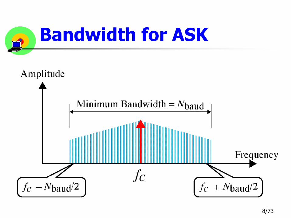
Amplitude Shift Keying (ASK)
8/73
Bandwidth for ASK

9/73
Frequency Shift Keying (FSK)

10/73
Bandwidth for FSK
11/73
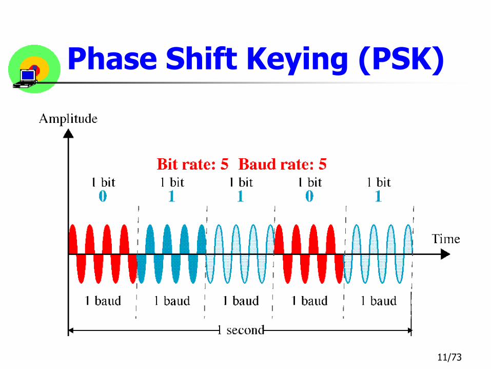
Phase Shift Keying (PSK)
12/73
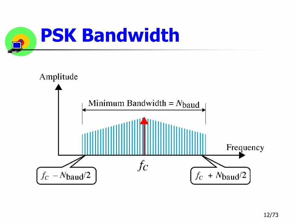
PSK Bandwidth

13/73
4-PSK

14/73
4-PSK Constellation
15/73
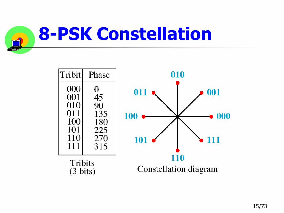
8-PSK Constellation

16/73
Quadrature Amplitude Modulation(QAM)

17/73
8-QAM Signal

18/73
Bit Rate and Baud Rate

19/73
Bit Rate and Baud Rate

20/73
Freq. Spectrum & Bandwidth
• Frequency Spectrum of a signal
•Collection of all the component frequencies of the signal
• Bandwidth of a signal
•The width of the frequency spectrum

21/73
Bandwidth

22/73
Modulation Technique
• Conversion process from data in NIC to radio waves• Narrow Band Modulation
• Spread Spectrum

23/73
Narrow Band Modulation
• Concentrate all Tx power within a narrow band
• Frequency Spacing
• TV, AM/FM radio

24/73
Narrow Band Example: FM Radio
• Analog/Analog Encoding• Concentrate all Tx power within a narrow band

25/73
Spread Spectrum Modulation
• A signal’s power over a wider band of frequencies
• Less susceptible to noise
• Trade-off between BW and Signal-to-Noise Ratio (process gain)

26/73
Narrow Band Signal
Spread Spectrum Modulation
Frequency
Amplitude
Narrow Band Interference
Spread Spectrum Signal

27/73
Spread Spectrum Modulation
• Frequency Hopping Spread Spectrum (FHSS)
• Direct Sequence Spread Spectrum (DSSS)
• Orthogonal Frequency Division Multiplexing (OFDM)

28/73
FHSS
• A carrier signal • hops from frequency to frequency as a
function of time
• Hopping code: • frequency use and order to transmit
• Federal Communications Corporation (FCC): Regulatory Agencies•>75 frequencies / transmission
•Max dwell time is 400 msec
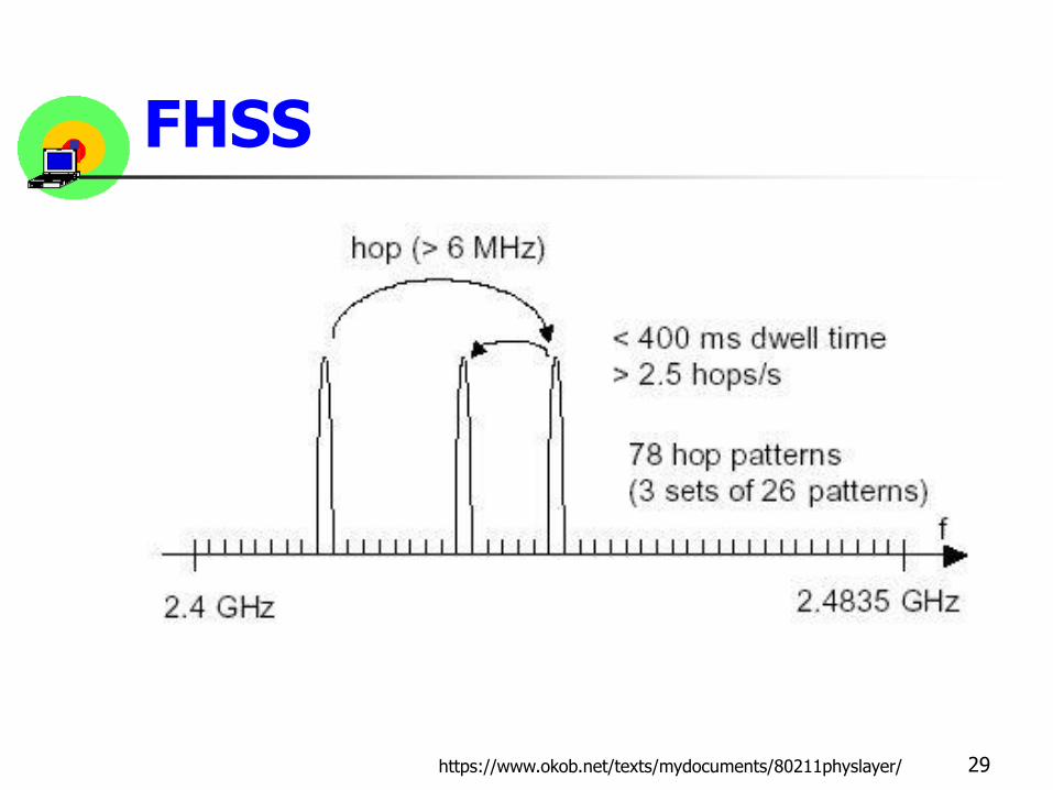
FHSS
29https://www.okob.net/texts/mydocuments/80211physlayer/

30/73
FHSS
Frequency(GHz)
Time
E
A
C
D
B
2.40 2.41 2.42 2.43 2.44 2.45
1
2
3
4
5
Hopping Pattern: E A C D B
E
A
C
D
B

31/73
FHSS & Noise
Frequency(GHz)
Time
B
2.40 2.41 2.42 2.43 2.44 2.45
1
2
3
4
5
ENoise
A Noise Noise
Noise
CNoise
Noise
DNoise
Noise
Noise
CNoise
Noise
Crash
E
A
C
D
B
Noise
Noise
Crash
Hopping Pattern: E A C D B

32/73
FHSS
• Achieve up to 2 Mbps
• Faster data rate high errors
• Reduce the interference effect
• Can operate radios with different hopping pattern in the same frequency band
•Hopping code used is called Orthogonal
33/73
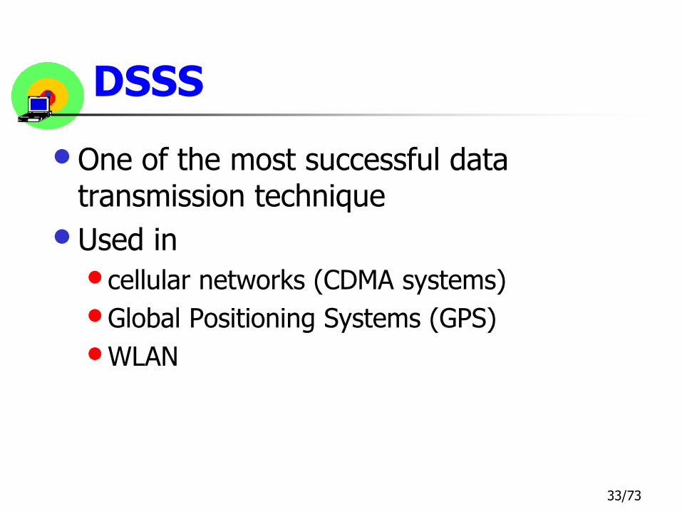
DSSS
• One of the most successful data transmission technique
• Used in
• cellular networks (CDMA systems)
•Global Positioning Systems (GPS)
•WLAN

34/73
DSSS
• Combines a data signal with higher data rate bit sequence
•Each bit multiple bits
•Actually sends XOR of a sending bit and n-random bits
• n-random bit n-bit Chipping Code
•Processing Gain

35/73
5-bit5-bit5-bit
DSSS: 5-bit Chipping Code
1
0Data Stream: 101
1
0
Random Seq: 01101 11000 10111
1
0
XOR (transmit): 10010 11000 01000

36/73
DSSS
• Spread the signal (n-time) across the frequency band
•Reduce power concentration over a frequency
• Spreading ratio (Chipping code):
•# of chip bits / data bit

Chipping Sequence
• Pseudo random binary sequence (PRN or PN)
• PRN sequence properties:
• Balanced sequence (difference between number of ones and zeros in the sequence is less or equal 1)
• Autocorrelation function of the sequence should be close to 0 everywhere except at the shift 0.
• White noise properties
37https://www.okob.net/texts/mydocuments/80211physlayer/

38/73
DSSS
• Higher spreading ratio
• Better interference resistance
• Lower data throughput
• Lower spreading ratio
• Lower interference resistance
• Better data throughput
• FCC regulations:
• Spreading ratio 10
• IEEE 802.11 11
39/73
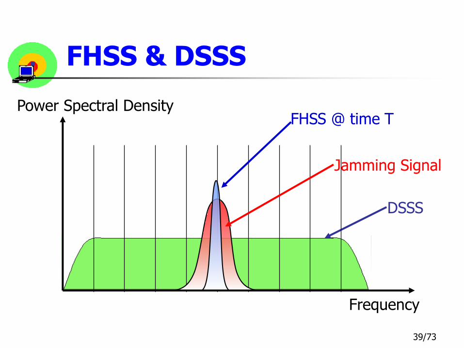
FHSS & DSSS
DSSS
Jamming Signal
FHSS @ time T
Frequency
Power Spectral Density

40/73
FHSS & DSSS
• DSSS can achieve much higher than 2 Mbps
• DSSS is harder to implement
• More expensive than FHSS
• FHSS is higher interference resistance
• DSSS transmits farther than FHSS ?
41/73
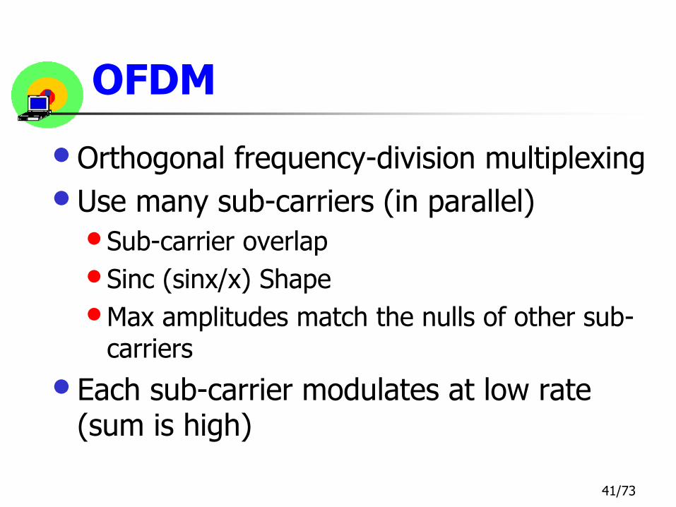
OFDM
• Orthogonal frequency-division multiplexing
• Use many sub-carriers (in parallel)
• Sub-carrier overlap
• Sinc (sinx/x) Shape
•Max amplitudes match the nulls of other sub-carriers
• Each sub-carrier modulates at low rate (sum is high)

sinc(x) Function
42

43/73
OFDM
• FDM principle
•more bandwidth efficiency
• Saving bandwidth by decreasing guard band
• Decrease the Interference among channels (cross talk)

44/73
Regular FDM
Frequency
Amplitude

45/73
OFDM
Amplitude
match the nulls of other sub-carriers
Max amplitudes
Frequency

Ts
Principles of orthogonal carriers
• Definition
•The cross correlation integral between two orthogonal sine waves, over the symbol duration Ts, is zero:
∫ A1sin(2πf1t + φ1) · A2sin(2πf2t + φ2) = 0
46www.dziwior.org/WirelessLAN/OFDM_Principles.html

Principles of orthogonal carriers
• The amplitude (An) and phase (φn) of each carrier can have any value, but must remain constant during the duration of the symbol (Ts). These characteristics are used to encode the data.
• It turns out that f1 − f2 = n · (1 / Ts), where n is an integer. The important fact about this orthogonal relationship is that a demodulator "looking at" f1 over the period Ts will be completely unaffected by f2 – without requiring an RF filter.
• You can have a set of orthogonal sine waves, such that fn = f0+ n · (1 / Ts), i.e. a set of carriers at regularly spaced frequency intervals, 1 / Ts apart. A demodulator "looking at" one carrier will be unaffected by the other carriers – provided it integrates over the period Ts.
47www.dziwior.org/WirelessLAN/OFDM_Principles.html

48/73
Outline
• Modulation Techniques
•Basic knowledge
•Narrow Band
• Spread Spectrum
• Physical Layer Architecture
• Physical Layer Operation
Physical Layer Architecture

49
Physical Layer
Physical Layer Architecture
PMD Sublayer
PMD SAP
PLCP Sublayer
PHY SAP
MAC Layer

50
PLCP Sublayer
• Physical Layer Convergence Procedure
• Communicate to MAC via primitives through Physical Layer Service Access Point (SAP)
• Prepare PLCP protocol data unit (PPDU) (append fields to MPDU)
• PPDU provides for asynchronous transfer of MPDU between stations

51
PMD Sublayer
• Physical Medium Dependent
• Provide actual transmission and reception of Physical Layer entities via wireless medium
• Interface directly to the medium
• Provides modulation and demodulation of the transmission frame

52/73
Outline
• Modulation Techniques
•Basic knowledge
•Narrow Band
• Spread Spectrum
• Physical Layer Architecture
• Physical Layer OperationPhysical Layer Operation

53
Physical Layer Operations
• 3 State machines
•Carrier Senses: determine the state of the medium
•Transmit: send the data frame
•Receive: receive the data frame

54
Physical Layer state
ตรวจสอบสื่อ
รับข้อมลูสง่ข้อมลู

55
Physical Layer Service Primitives
MAC PLCP PLCP MAC Description
PHY-TXSTART.request PHY-TXSTART.confirm Start TX
PHY-DATA.request PHY-DATA.confirm Transfer Data
PHY-TXEND.request PHY-TXEND.confirm End TX
PHY-CCARESET.request PHY-CCARESET.confirm Reset Clear Channel Assessment state machine
PHY-CCA.indication (busy/idle : send every channel changes state)
PHY-DATA.indication Transfer Data
PHY-RXSTART.indication
PHY-RXEND.indication
Received a valid start frame/PLCP header

MAC PMDPLCP
Carrier Sense Function
• Station is not in Tx or Rx mode
• Clear channel assessment
• Medium Idle
• Clear channel assessment
• Medium Busy
• Check preamblemonitor header
• Try to synchronize

MAC PLCP PMD
Transmit Function
•Switch to TX mode
… …
•Sending preamble & header to antenna @ 1 Mbps•Transmit data @ specified rate
•Switch to RX mode
…

MAC PMDPLCP
Receive Function
• Clear channel assessment foundmedia busy
• Check preamblemonitor header
• Final Octet
…
• Check Power level > 85 dBm
• Check CRC
• Set octet counter
……

59
Multiple Antenna Diversities
• Receive function will operate with• Single Antenna
• Multiple Antennas
• Signal Degradation Factors• Distance
• Atmosphere
• Barrier
• Multiple-path propagation• Decrease the signal strength
• Use multiple antennas (diversity) to improve the received signal

Multiple Antennas
60
Wireless Transmitter
Wireless Receiver
SISO
Wireless Transmitter
Wireless Receiver
::
SIMO
Wireless Transmitter
Wireless Receiver
:: MISO
Wireless Transmitter
Wireless Receiver
::
:: MIMO
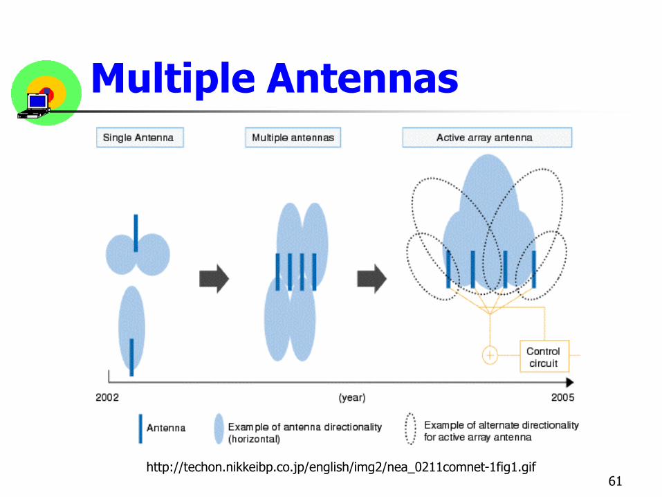
Multiple Antennas
61http://techon.nikkeibp.co.jp/english/img2/nea_0211comnet-1fig1.gif

62
IEEE 802.11 PHY Layer
• FHSS Physical Layer
• DSSS Physical Layer
• Infrared (IR) Physical Layer

63
FHSS Physical Layer
• Low cost
• Low power consumption
• Most tolerant to noise
• Low potential data rate
• Medium range (< DSSS)

64
FHSS Architecture
• FHSS PLCP Sublayer
• FHSS PMD Sublayer
• Primitives

65
FHSS PLCP frame
Start FrameDelimiter
PLW PSFHeaderErrorCheck
Whitened PSDU
80 bits 16 bits 12 bits 4 bits 16 bits 0-4095 Octets
SYNC
0 & 1 alternating : synchronization purpose
PSDU Length word
0000110010111101: define the beginning of a frame
16-bit CRC
Payload (MPDU)Reduce DC bias, scramble
PLCP Signaling Field: data rate (1- 4.5 Mbps)
PLCP Preamble PLCP Header
PSDU=PLCP Service Data Unit

66
FHSS HW
พีแอลซีพี
Data Whitenerการเปล่ียน
สญัญลกัษณ์การกรองแบบ
Guassianมอดดเูลชัน่แบบ GFSK
พีแอลซีพี
พีแอลซีพี
Data Dewhitener
การกูคื้น ช่วงการกระโดด
ฝ่ังสง่
ฝ่ังรับ
ปรับปรุงจาก 802.11 Wireless Networks, Gast, O’reilly
67
FHSS PMD
• Perform actual Tx/Rx of PPDU by hopping between channel (hopping sequence)
• Provides FHSS modulation/demodulation
68
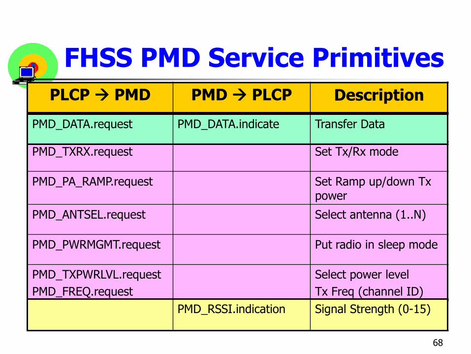
FHSS PMD Service Primitives
PLCP PMD PMD PLCP Description
PMD_TXRX.request Set Tx/Rx mode
PMD_PA_RAMP.request Set Ramp up/down Tx power
PMD_ANTSEL.request Select antenna (1..N)
PMD_PWRMGMT.request Put radio in sleep mode
PMD_TXPWRLVL.request
PMD_FREQ.request
Select power level
Tx Freq (channel ID)
PMD_DATA.request PMD_DATA.indicate Transfer Data
PMD_RSSI.indication Signal Strength (0-15)

69
DSSS Physical Layer
• High cost
• High power consumption
• High potential data rate
• More range

70
DSSS Architecture
• DSSS PLCP Sublayer
• DSSS PMD Sublayer
• Primitives

71
DSSS PLCP frame
0 & 1 alternating : synchronization purpose
Modulation type: data rate
1111001110100000: define the beginning of a frame
#microsec. To transmit the MPDU
16-bit CRC
Reserved
PLCP Preamble PLCP Header
Start FrameDelimiter
Signal ServiceFrameCheck
SequenceMPDU
128 bits 16 bits 8 bits 8 bits 16 bits
SYNC Length
8 bits
DSSS
• Preamble and PLCP header are transmitted at 1Mbps
• Regardless of data transmission speed
• Payload prepared by the MAC layer is sent at the rate specified in the services field
• The transmitter uses DBPSK (1Mbps) and DQPSK(2Mbps) modulation
72

73
DSSS HW
ปรับปรุงจาก 802.11 Wireless Networks, Gast, O’reilly
พีแอลซีพี ตวักระจายตวักรอง
Transmit Markมอดดเูลชัน่แบบDBPSK/DQPSK
Descrambler
Correlator
ดีมอดดเูลชัน่แบบ DBPSK/DQPSK
การกูคื้น ช่วงเวลา
ฝ่ังสง่
ฝ่ังรับ
ล าดบัชิปปิง้
พีแอลซีพี

Complementary Code Keying (CCK)
• 1998
• Proposed by Lucent Technologies and Harris Semiconductor (later owned by Intersil)
• Achieve 5.5Mbps and 11Mbps Tx rates
74https://www.okob.net/texts/mydocuments/80211physlayer/

CCK
• IEEE adopted the CCK and released the 802.11b in 1999
• new option to transmit PLCP header with a short (56 bits) preamble
• only the Synchronization and Start Frame Delimiter fields are transmitted at 1Mbps
• The rest of the PLCP header is transmitted at 2Mbps (using DSSS DQPSK)
• data payload at either the same 2Mbps, or using CCK at 5.5Mbps or 11Mbps.
75

CCK
• based on polyphase complementary codes
• not binary complex codes
• real component placed in the vertical plane
• complex component in the horizontal plane
76

CCK
• The modulator uses
• 6 bits of each byte to pick one of 64 unique orthogonal eight chips long polyphase complementary codes
• two bits of the byte are used to rotate the whole code word (0, 90, 180 or 270 degrees)
• real and complex parts of the resulted code go to the I(in-phase) and Q(quadrature) channels of the IQ modulator
77

78
More on Preamble Frame
http://searchmobilecomputing.techtarget.com/searchMobileComputing/downloads/CWAP_ch8.pdf

79
Signal Field (802.11b)
Data Rate (Mbps)
Signal Field Value
1 00001010
2 00010100
5.5 00110111
11 01101110

80
DSSS PMD
• Perform actual Tx/Rx of PPDU
• Provides DSSS modulation/demodulation

81
DSSS PMD Service Primitives
PLCP PMD PMD PLCP Description
PMD_TXSTART.request
PMD_TXEND.request PMD_TXPWRLVL.request
Start Tx
End Tx
Select power level
PMD_ANTSEL.request PMD_ANTSEL.indicate Select antenna (1..N)
PMD_RATE.request PMD_RATE.indicate Select data rate
PMD_ED.request PMD_ED.indicate Energy > Threshold
PMD_DATA.request PMD_DATA.indicate Transfer Data
PMD_RSSI.indication
PMD_SQ.indicate
PMD_CS.indicate
PMD_CAA.indicate
Signal Strength (0-15)
Signal Quality (PN code)
Valid 802.11 DS
Detect RF as CCA algo.

82
IR Physical Layer
• Lowest cost
• Highest tolerant to RF noise
• Lowest range
• Need ceiling
• More secure
• No frequency regulating
• No product ?
• IrDA: Infrared Data Association Standard

83
IR Architecture
• IR PLCP Sublayer
• IR PMD Sublayer

84
IR PLCP frame
Pulse alternating : synchronization purpose
Data rate
1001: define the beginning of a frame
#microsec. To transmit the MPDU
16-bit CRC
Specified for 1 and 2 Mbps
PLCP Preamble PLCP Header
Start FrameDelimiter
DataRate
DC LevelAdjust.
FrameCheck
SequenceMPDU
57-73 slots 4 slots 3 slots 32 slots 16 slots
SYNC Length
16 slots 0-2500 octets

85
IR PMD
• Mostly use diffused infrared
• Perform actual Tx/Rx of PPDU, translate binary to infrared light
• Provides IR modulation/demodulation

86
IR PMD
• Noise affects amplitude (not phase)
Pulse position reduces interference
• Pulse position modulation :PPM
•Vary position of pulse
• For 1 Mbps 16 PPM
• For 2 Mbps 4 PPM

87
Pulse Position Modulation
Data bits 16-PPM signal
0000 0000 0000 0000 0001
0001 0000 0000 0000 0010
… …
1000 1000 0000 0000 0000
Data bits 4-PPM signal
00 0001
01 0010
10 0100
11 1000

88
OFDM PLCP Frame
Rate Resv. MAC Data
12 สญัญลกัษณ์
SYNC
พรีแอมเบิล้ พีแอลซีพี เฮดเดอร์
Length
ขนาดเปลีย่นแปลงได ้4 บติ 1 บติ 12 บติ
พารติี้
1 บติ
Tail
6 บติ
Service
16 บติ

DSSS-OFDM PPDU
89http://wireless.agilent.com/wireless/helpfiles/n7617b/dsss-ofdm_ppdu_format_short.jpg

90
Transmission Rate
บติข้อมูล ความเร็วที่ได้ (Mbps) ช่วงความเร็ว
1101 6 1(BPSK)1111 9
0101 12 2(QPSK)0111 18
1001 24 3(16-QAM)1011 36
0001 48 4(64-QAM)0011 54

IEEE 802.11g OFDM
91https://www.okob.net/texts/mydocuments/80211physlayer/