Embed Size (px)
Citation preview
Wireless LANs: 802.11 and Mobile IP
Sridhar IyerLeena ChandranWadia
K R School of Information TechnologyIIT Bombay
{sri, leena}@it.iitb.ac.inhttp://www.it.iitb.ac.in/
IIT Bombay ICPWC'02 2
Outline
Overview of wireless networks– Singlehop wireless: Cellular, Wireless LANs (WLANs)– multiple wireless hops – Mobile ad hoc networks (MANETS)
Challenges of wireless communications IEEE 802.11
– spread spectrum and physical layer specification– MAC functional specification: DCF mode
• role in WLANs – infrastructure networks• role in MANETs
– MAC functional specification: PCF mode
Mobile IPv4 Mobile IPv6
IIT Bombay ICPWC'02 3
References
http://standards.ieee.org/getieee802/802.11.html IEEE Computer Society 1999, Wireless LAN MAC and PHY layer specification
J. Schiller, “Mobile Communications”, Addison Wesley, 1999. – several figures
Short tutorials on 802.11 and spread spectrum by J.Zyren, A.Petrick, C.Andren http://www.intersil.com
Mobile IPv4 – RFC 3344 (main) IPv6 and Mobile IPv6
– many RFCs, Internet drafts– http://www.iprg.nokia.com/~charliep/
IIT Bombay ICPWC'02 4
Overview of wireless networks
IIT Bombay ICPWC'02 5
Wireless networks
Access computing/communication services, on the move
Cellular Networks– traditional base station infrastructure systems
Wireless LANs– infrastructure as well as adhoc networks possible– very flexible within the reception area– low bandwidth compared to wired networks (110 Mbit/s)
Multihop Ad hoc Networks– useful when infrastructure not available, impractical, or expensive– military applications, rescue, home networking
IIT Bombay ICPWC'02 6
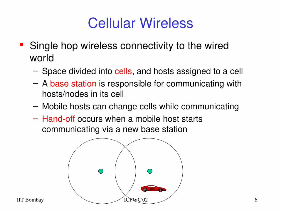
Cellular Wireless Single hop wireless connectivity to the wired
world– Space divided into cells, and hosts assigned to a cell– A base station is responsible for communicating with
hosts/nodes in its cell– Mobile hosts can change cells while communicating– Handoff occurs when a mobile host starts
communicating via a new base station
IIT Bombay ICPWC'02 7
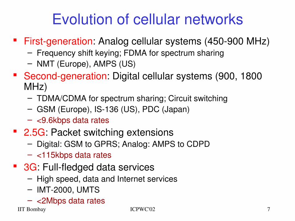
Evolution of cellular networks Firstgeneration: Analog cellular systems (450900 MHz)
– Frequency shift keying; FDMA for spectrum sharing– NMT (Europe), AMPS (US)
Secondgeneration: Digital cellular systems (900, 1800 MHz)– TDMA/CDMA for spectrum sharing; Circuit switching– GSM (Europe), IS136 (US), PDC (Japan)– <9.6kbps data rates
2.5G: Packet switching extensions– Digital: GSM to GPRS; Analog: AMPS to CDPD– <115kbps data rates
3G: Fullfledged data services– High speed, data and Internet services– IMT2000, UMTS– <2Mbps data rates
IIT Bombay ICPWC'02 8
Wireless LANs
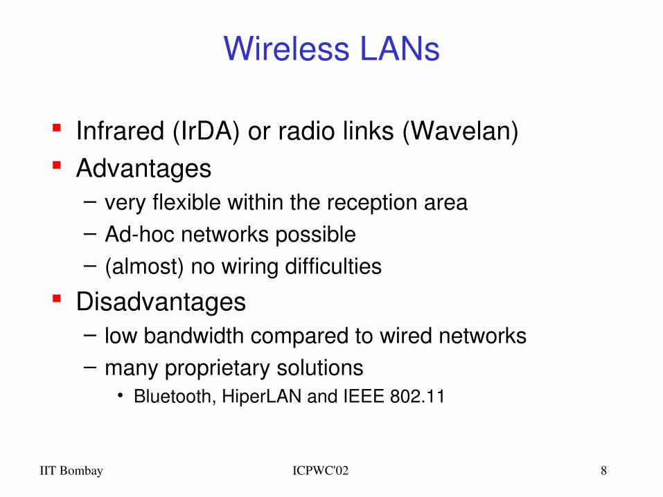
Infrared (IrDA) or radio links (Wavelan) Advantages
– very flexible within the reception area – Adhoc networks possible– (almost) no wiring difficulties
Disadvantages– low bandwidth compared to wired networks– many proprietary solutions
• Bluetooth, HiperLAN and IEEE 802.11
IIT Bombay ICPWC'02 9
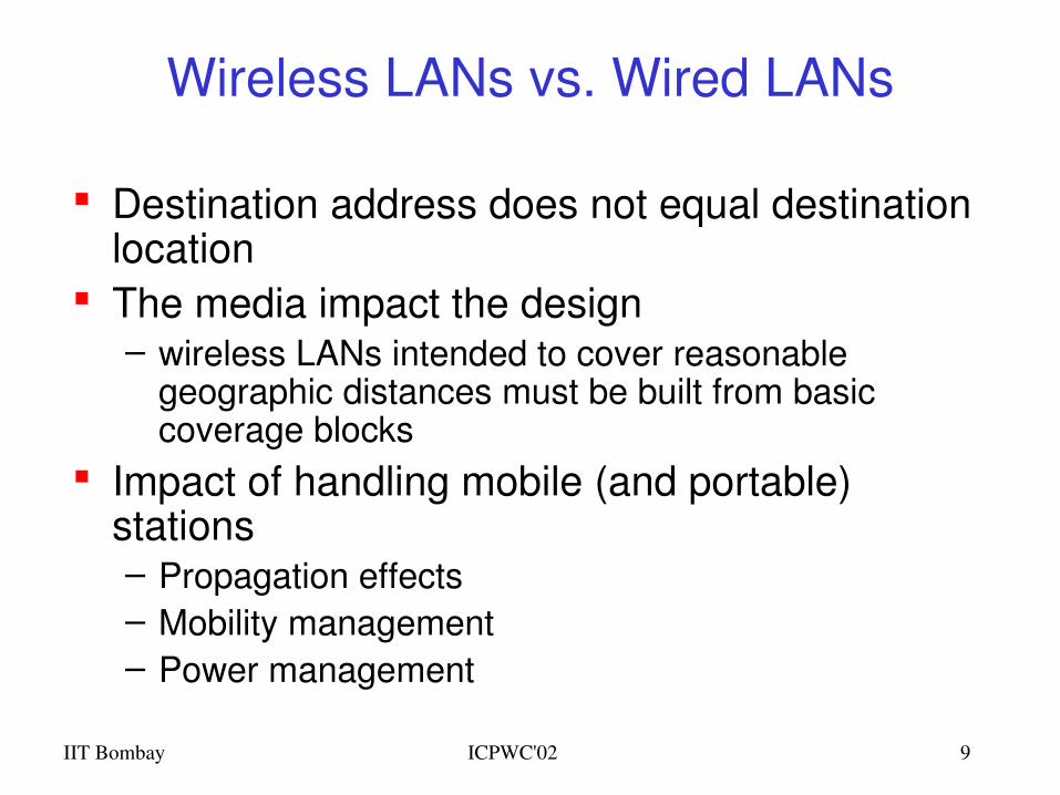
Wireless LANs vs. Wired LANs
Destination address does not equal destination location
The media impact the design– wireless LANs intended to cover reasonable
geographic distances must be built from basic coverage blocks
Impact of handling mobile (and portable) stations– Propagation effects – Mobility management– Power management
IIT Bombay ICPWC'02 10
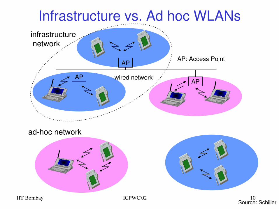
Infrastructure vs. Ad hoc WLANsinfrastructure network
adhoc network
APAP
AP
wired network
AP: Access Point
Source: Schiller
IIT Bombay ICPWC'02 11
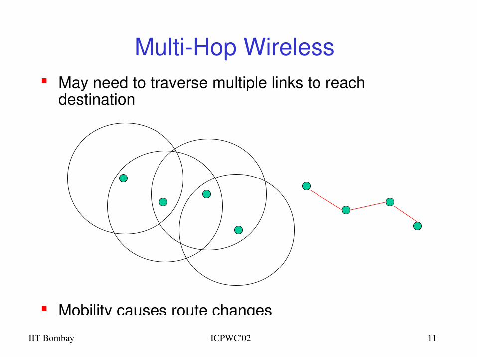
MultiHop Wireless May need to traverse multiple links to reach
destination
Mobility causes route changes
IIT Bombay ICPWC'02 12
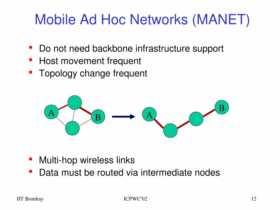
Mobile Ad Hoc Networks (MANET)
Do not need backbone infrastructure support Host movement frequent Topology change frequent
Multihop wireless links Data must be routed via intermediate nodes
A B AB
IIT Bombay ICPWC'02 13
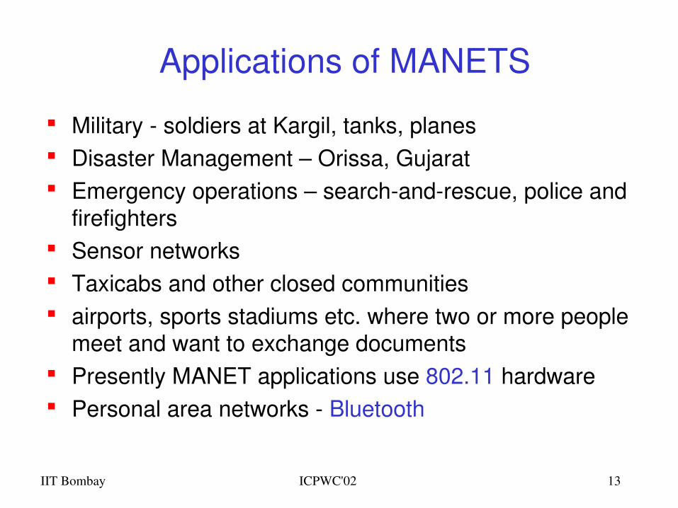
Applications of MANETS
Military soldiers at Kargil, tanks, planes Disaster Management – Orissa, Gujarat Emergency operations – searchandrescue, police and
firefighters Sensor networks Taxicabs and other closed communities airports, sports stadiums etc. where two or more people
meet and want to exchange documents Presently MANET applications use 802.11 hardware Personal area networks Bluetooth
IIT Bombay ICPWC'02 14
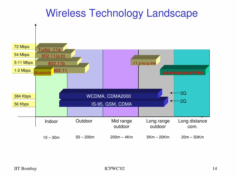
384 Kbps
56 Kbps
54 Mbps
72 Mbps
511 Mbps
12 Mbps 802.11
Wireless Technology Landscape
Bluetooth
802.11b
802.11{a,b}Turbo .11a
Indoor
10 – 30m
IS95, GSM, CDMA
WCDMA, CDMA2000
Outdoor
50 – 200m
Mid rangeoutdoor
200m – 4Km
Long rangeoutdoor
5Km – 20Km
Long distance com.
20m – 50Km
µwave ptop links
.11 ptop link
2G
3G
IIT Bombay ICPWC'02 15
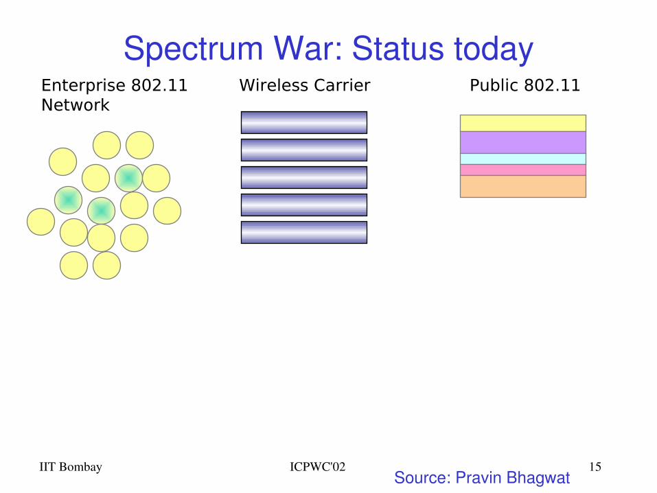
Spectrum War: Status todayEnterprise 802.11Network
Public 802.11Wireless Carrier
Source: Pravin Bhagwat
IIT Bombay ICPWC'02 16
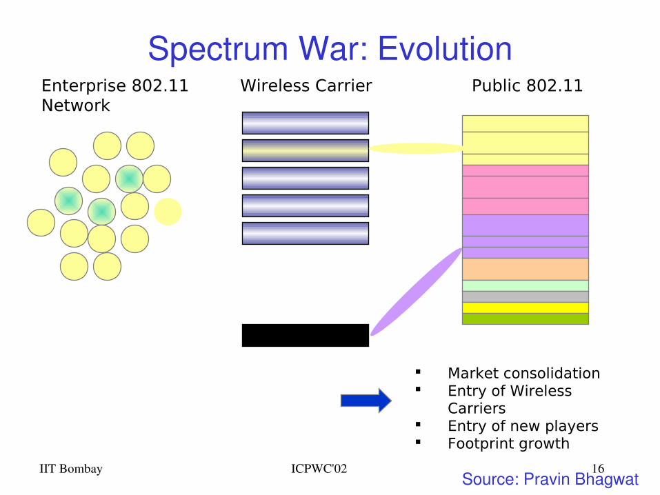
Spectrum War: EvolutionEnterprise 802.11Network
Public 802.11Wireless Carrier
Market consolidation Entry of Wireless
Carriers Entry of new players Footprint growth
Source: Pravin Bhagwat
IIT Bombay ICPWC'02 17
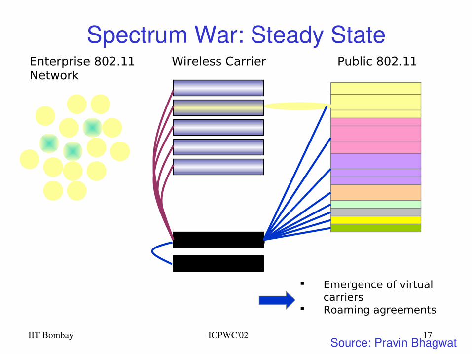
Spectrum War: Steady StateEnterprise 802.11Network
Public 802.11Wireless Carrier
Virtual Carrier
Emergence of virtual carriers
Roaming agreements
Source: Pravin Bhagwat
IIT Bombay ICPWC'02 18
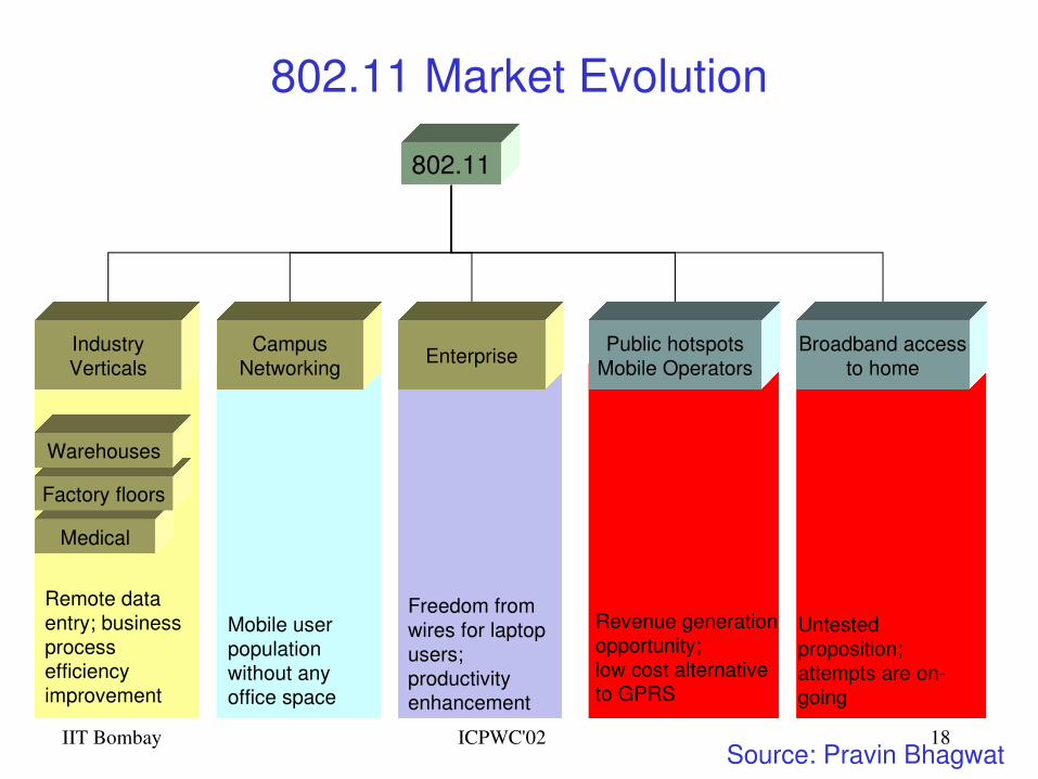
802.11 Market Evolution
802.11
CampusNetworking
Mobile userpopulation without anyoffice space
Enterprise
Freedom fromwires for laptopusers;productivity enhancement
IndustryVerticals
Medical
Factory floors
Warehouses
Remote data entry; business process efficiency improvement
Public hotspotsMobile Operators
Revenue generationopportunity;low cost alternativeto GPRS
Broadband accessto home
Untested proposition;attempts are ongoing
Source: Pravin Bhagwat
Challenges of Wireless Communications
IIT Bombay ICPWC'02 20
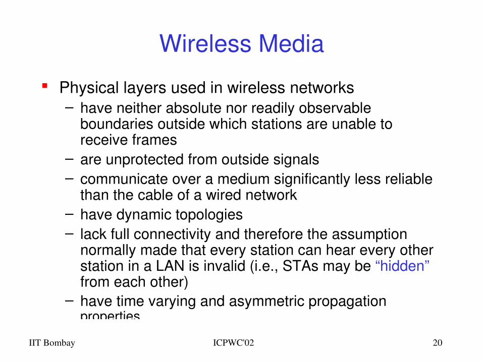
Wireless Media
Physical layers used in wireless networks– have neither absolute nor readily observable
boundaries outside which stations are unable to receive frames
– are unprotected from outside signals– communicate over a medium significantly less reliable
than the cable of a wired network– have dynamic topologies– lack full connectivity and therefore the assumption
normally made that every station can hear every other station in a LAN is invalid (i.e., STAs may be “hidden” from each other)
– have time varying and asymmetric propagation properties
IIT Bombay ICPWC'02 21
Limitations of the mobile environment• Limitations of the Wireless Network
• limited communication bandwidth • frequent disconnections• heterogeneity of fragmented networks
• Limitations Imposed by Mobility• route breakages• lack of mobility awareness by system/applications
• Limitations of the Mobile Device• short battery lifetime• limited capacities
IIT Bombay ICPWC'02 22
Wireless v/s Wired networks Regulations of frequencies
– Limited availability, coordination is required– useful frequencies are almost all occupied
Bandwidth and delays– Low transmission rates
• few Kbps to some Mbps.– Higher delays
• several hundred milliseconds– Higher loss rates
• susceptible to interference, e.g., engines, lightning
Always shared medium– Lower security, simpler active attacking– radio interface accessible for everyone– Fake base stations can attract calls from mobile phones– secure access mechanisms important
IIT Bombay ICPWC'02 23
Difference Between Wired and Wireless
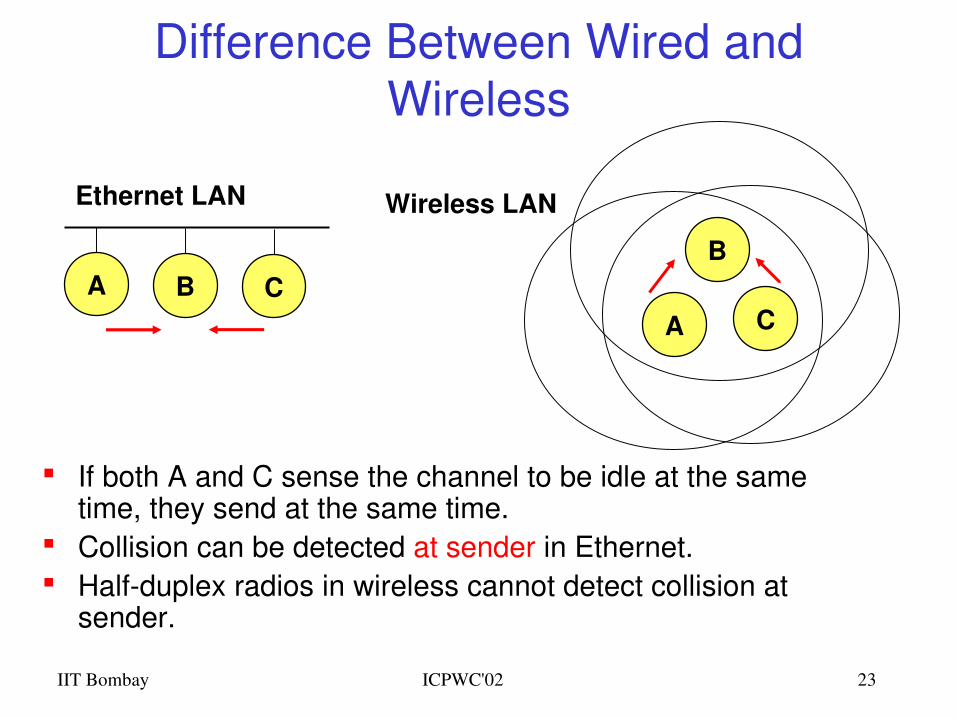
If both A and C sense the channel to be idle at the same time, they send at the same time.
Collision can be detected at sender in Ethernet. Halfduplex radios in wireless cannot detect collision at
sender.
A B CA
B
C
Ethernet LAN Wireless LAN
IIT Bombay ICPWC'02 24
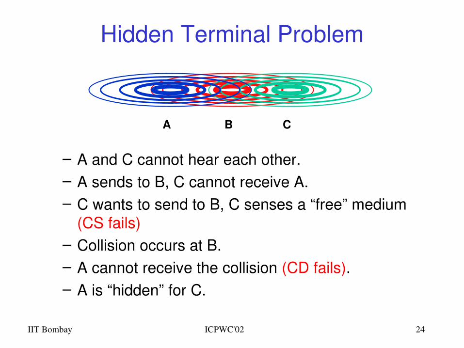
– A and C cannot hear each other.– A sends to B, C cannot receive A. – C wants to send to B, C senses a “free” medium
(CS fails)– Collision occurs at B.– A cannot receive the collision (CD fails).– A is “hidden” for C.
Hidden Terminal Problem
BA C
IIT Bombay ICPWC'02 25
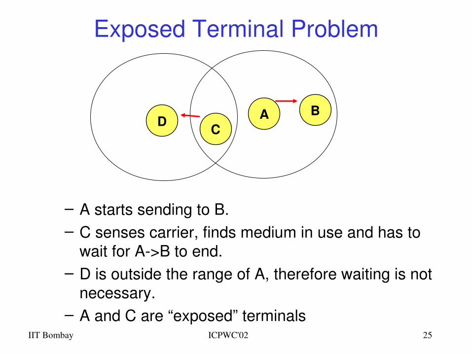
Exposed Terminal Problem
– A starts sending to B.– C senses carrier, finds medium in use and has to
wait for A>B to end.– D is outside the range of A, therefore waiting is not
necessary.– A and C are “exposed” terminals
A BCD
IIT Bombay ICPWC'02 26
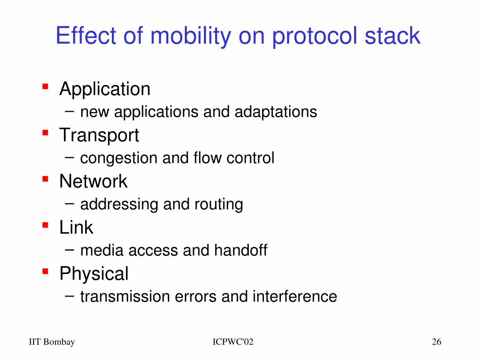
Effect of mobility on protocol stack
Application– new applications and adaptations
Transport– congestion and flow control
Network– addressing and routing
Link– media access and handoff
Physical– transmission errors and interference
802.11based Wireless LANsArchitecture and Physical Layer
IIT Bombay ICPWC'02 28
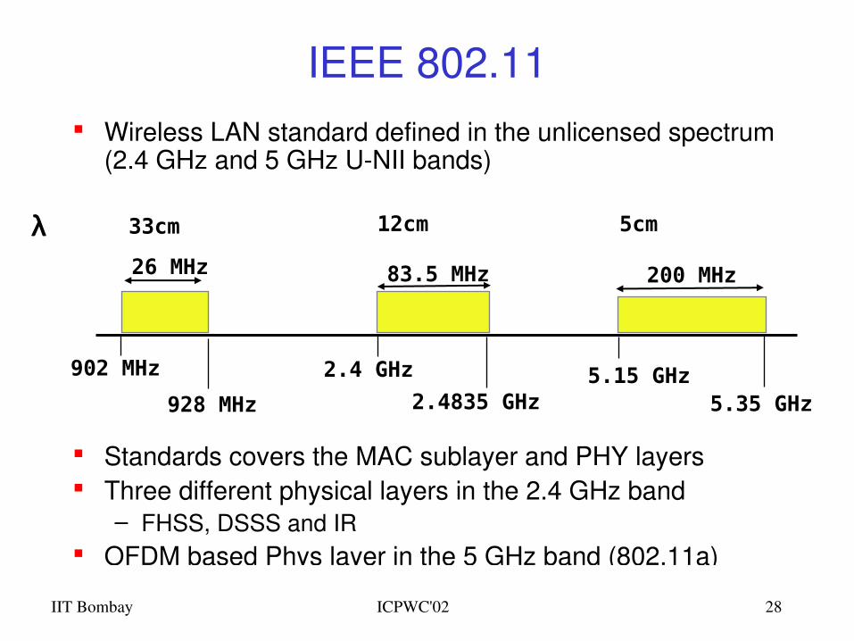
IEEE 802.11 Wireless LAN standard defined in the unlicensed spectrum
(2.4 GHz and 5 GHz UNII bands)
Standards covers the MAC sublayer and PHY layers Three different physical layers in the 2.4 GHz band
– FHSS, DSSS and IR OFDM based Phys layer in the 5 GHz band (802.11a)
902 MHz
928 MHz
26 MHz 83.5 MHz 200 MHz
2.4 GHz
2.4835 GHz5.15 GHz
5.35 GHz
λ 33cm 12cm 5cm
IIT Bombay ICPWC'02 29
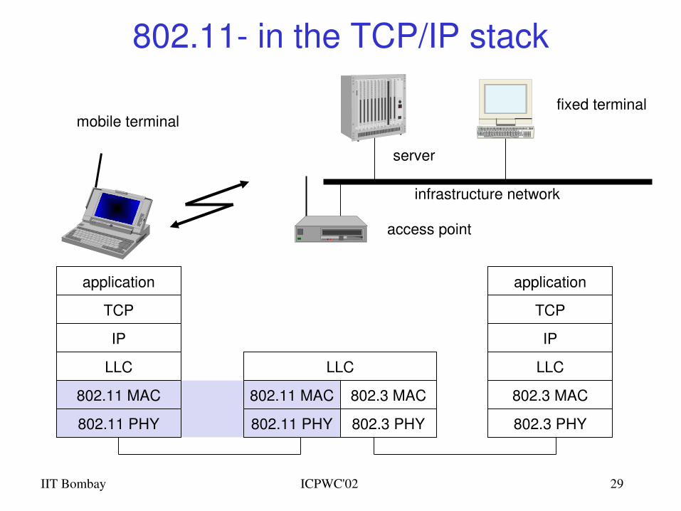
802.11 in the TCP/IP stack
mobile terminal
access point
server
fixed terminal
application
TCP
802.11 PHY
802.11 MAC
IP
802.3 MAC
802.3 PHY
application
TCP
802.3 PHY
802.3 MAC
IP
802.11 MAC
802.11 PHY
LLC
infrastructure network
LLC LLC
IIT Bombay ICPWC'02 30
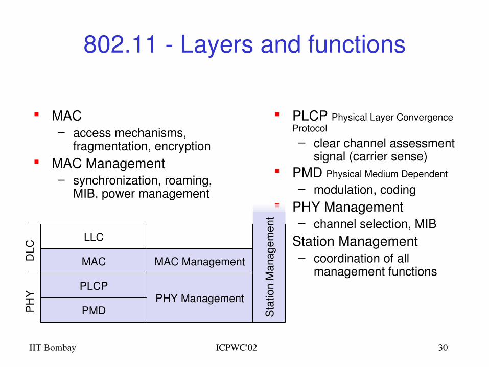
802.11 Layers and functions
PLCP Physical Layer Convergence Protocol
– clear channel assessment signal (carrier sense)
PMD Physical Medium Dependent
– modulation, coding PHY Management
– channel selection, MIB Station Management
– coordination of all management functions
PMD
PLCP
MAC
LLC
MAC Management
PHY Management
MAC– access mechanisms,
fragmentation, encryption MAC Management
– synchronization, roaming, MIB, power management
PH
YD
LC
Sta
tion
Man
agem
ent
IIT Bombay ICPWC'02 31
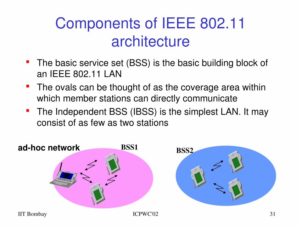
Components of IEEE 802.11 architecture
The basic service set (BSS) is the basic building block of an IEEE 802.11 LAN
The ovals can be thought of as the coverage area within which member stations can directly communicate
The Independent BSS (IBSS) is the simplest LAN. It may consist of as few as two stations
adhoc network BSS2BSS1
IIT Bombay ICPWC'02 32
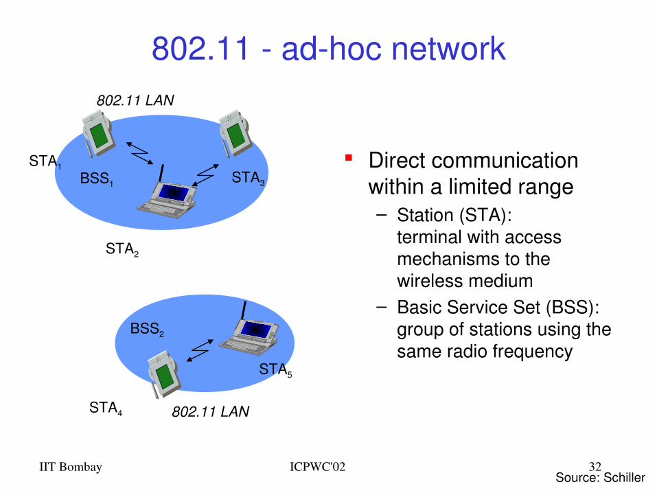
802.11 adhoc network
Direct communication within a limited range– Station (STA):
terminal with access mechanisms to the wireless medium
– Basic Service Set (BSS):group of stations using the same radio frequency
802.11 LAN
BSS2
802.11 LAN
BSS1
STA1
STA4
STA5
STA2
STA3
Source: Schiller
IIT Bombay ICPWC'02 33
Distribution System
Portal
802.x LAN
Access Point
802.11 LAN
BSS2
802.11 LAN
BSS1
Access Point
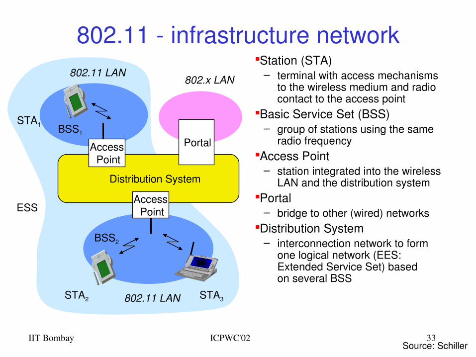
802.11 infrastructure networkStation (STA)
– terminal with access mechanisms to the wireless medium and radio contact to the access point
Basic Service Set (BSS)– group of stations using the same
radio frequencyAccess Point
– station integrated into the wireless LAN and the distribution system
Portal– bridge to other (wired) networks
Distribution System– interconnection network to form
one logical network (EES: Extended Service Set) based on several BSS
STA1
STA2 STA3
ESS
Source: Schiller
IIT Bombay ICPWC'02 34
Distribution System (DS) concepts
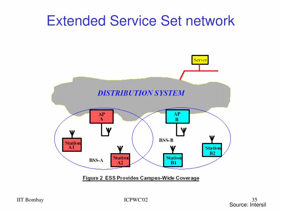
The Distribution system interconnects multiple BSSs 802.11 standard logically separates the wireless
medium from the distribution system – it does not preclude, nor demand, that the multiple media be same or different
An Access Point (AP) is a STA that provides access to the DS by providing DS services in addition to acting as a STA.
Data moves between BSS and the DS via an AP The DS and BSSs allow 802.11 to create a wireless
network of arbitrary size and complexity called the Extended Service Set network (ESS)
IIT Bombay ICPWC'02 35
Extended Service Set network
Source: Intersil
IIT Bombay ICPWC'02 36
802.11 Physical layer
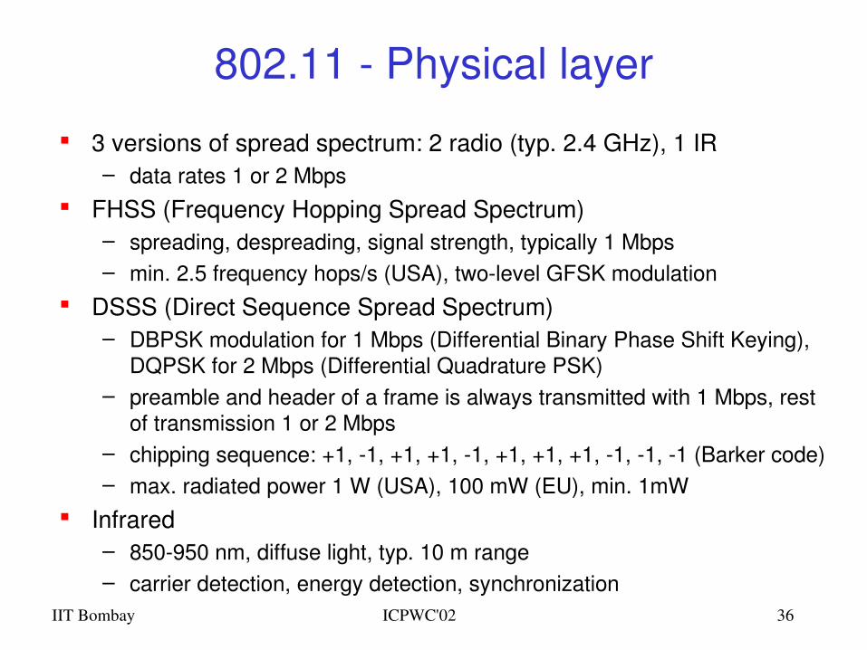
3 versions of spread spectrum: 2 radio (typ. 2.4 GHz), 1 IR– data rates 1 or 2 Mbps
FHSS (Frequency Hopping Spread Spectrum)– spreading, despreading, signal strength, typically 1 Mbps– min. 2.5 frequency hops/s (USA), twolevel GFSK modulation
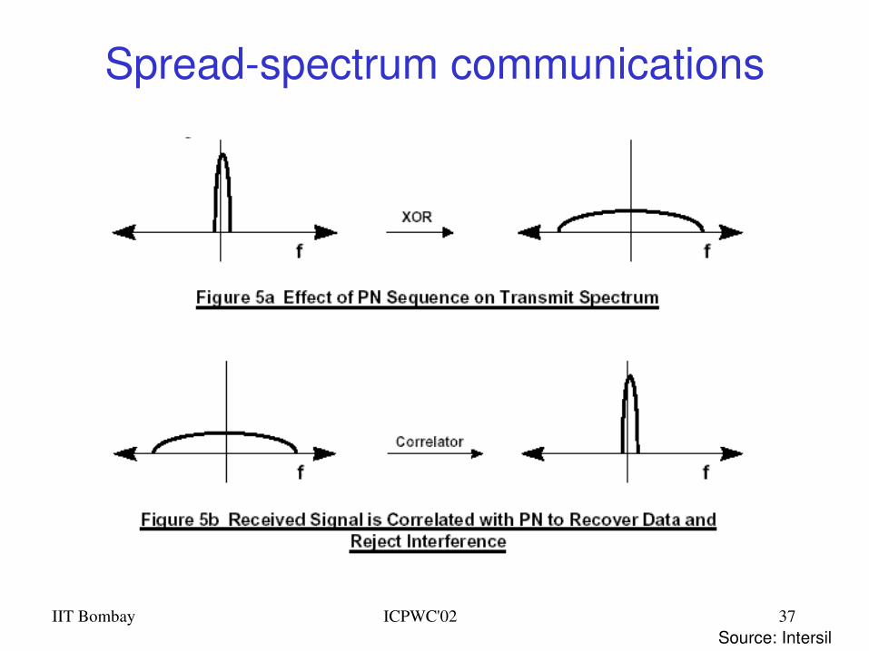
DSSS (Direct Sequence Spread Spectrum)– DBPSK modulation for 1 Mbps (Differential Binary Phase Shift Keying),
DQPSK for 2 Mbps (Differential Quadrature PSK)– preamble and header of a frame is always transmitted with 1 Mbps, rest
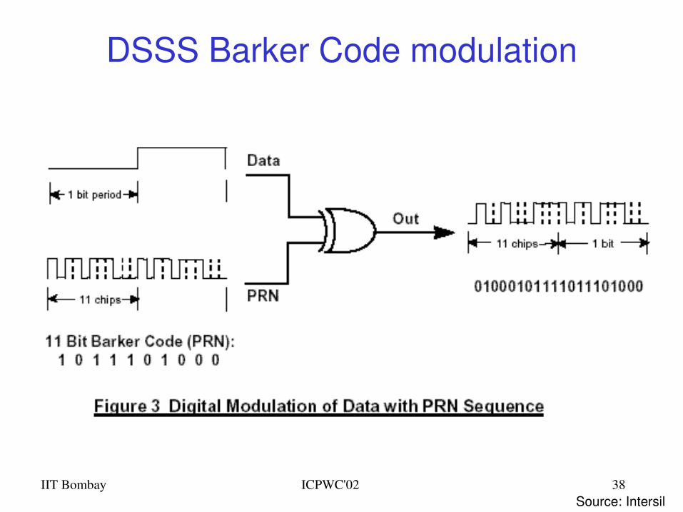
of transmission 1 or 2 Mbps– chipping sequence: +1, 1, +1, +1, 1, +1, +1, +1, 1, 1, 1 (Barker code)– max. radiated power 1 W (USA), 100 mW (EU), min. 1mW
Infrared– 850950 nm, diffuse light, typ. 10 m range– carrier detection, energy detection, synchronization
IIT Bombay ICPWC'02 37
Spreadspectrum communications
Source: Intersil
IIT Bombay ICPWC'02 38
DSSS Barker Code modulation
Source: Intersil
IIT Bombay ICPWC'02 39
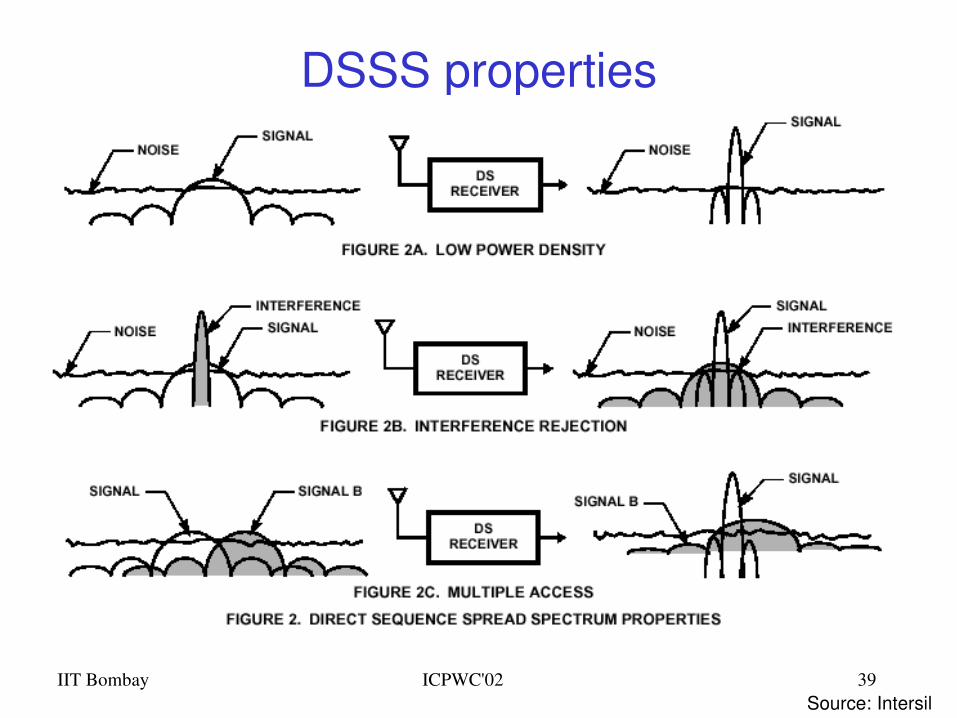
DSSS properties
Source: Intersil
IIT Bombay ICPWC'02 40
Hardware
Original WaveLAN card (NCR)– 914 MHz Radio Frequency– Transmit power 281.8 mW– Transmission Range ~250 m (outdoors) at 2Mbps– SNRT 10 dB (capture)
WaveLAN II (Lucent)– 2.4 GHz radio frequency range– Transmit Power 30mW– Transmission range 376 m (outdoors) at 2 Mbps (60m
indoors)– Receive Threshold = 81dBm – Carrier Sense Threshold = 111dBm
Many others….Agere, Cisco,………
802.11based Wireless LANsMAC functional spec DCF
IIT Bombay ICPWC'02 42
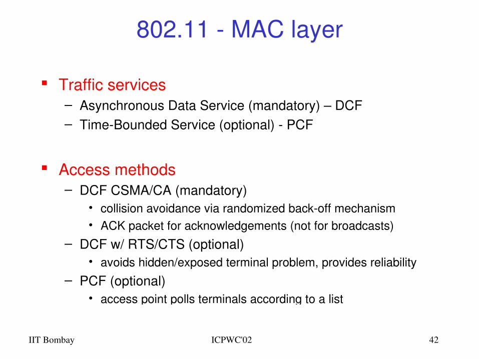
802.11 MAC layer
Traffic services– Asynchronous Data Service (mandatory) – DCF– TimeBounded Service (optional) PCF
Access methods– DCF CSMA/CA (mandatory)
• collision avoidance via randomized backoff mechanism• ACK packet for acknowledgements (not for broadcasts)
– DCF w/ RTS/CTS (optional)• avoids hidden/exposed terminal problem, provides reliability
– PCF (optional)• access point polls terminals according to a list
IIT Bombay ICPWC'02 43
t
medium busy
DIFSDIFS
next frame
contention window(randomized backoffmechanism)
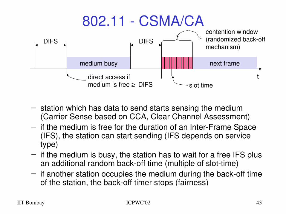
802.11 CSMA/CA
– station which has data to send starts sensing the medium (Carrier Sense based on CCA, Clear Channel Assessment)
– if the medium is free for the duration of an InterFrame Space (IFS), the station can start sending (IFS depends on service type)
– if the medium is busy, the station has to wait for a free IFS plus an additional random backoff time (multiple of slottime)
– if another station occupies the medium during the backoff time of the station, the backoff timer stops (fairness)
slot timedirect access if medium is free ≥ DIFS
IIT Bombay ICPWC'02 44
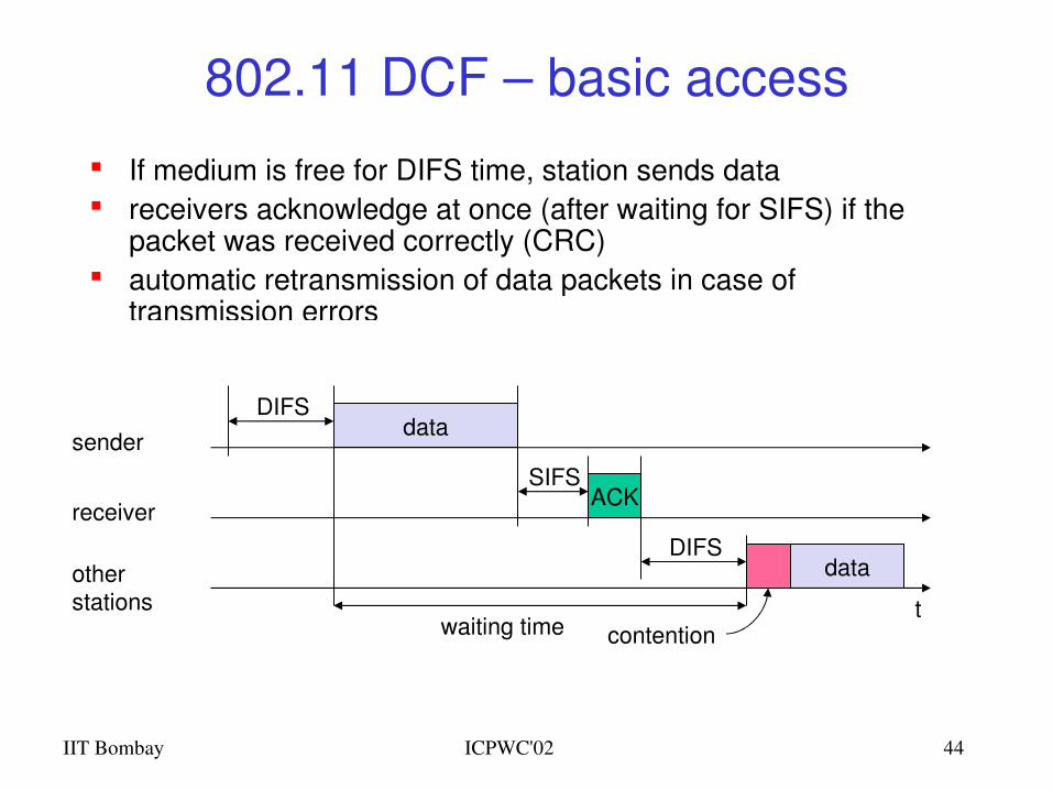
802.11 DCF – basic access
If medium is free for DIFS time, station sends data receivers acknowledge at once (after waiting for SIFS) if the
packet was received correctly (CRC) automatic retransmission of data packets in case of
transmission errors
t
SIFS
DIFS
data
ACK
waiting time
otherstations
receiver
senderdata
DIFS
contention
IIT Bombay ICPWC'02 45
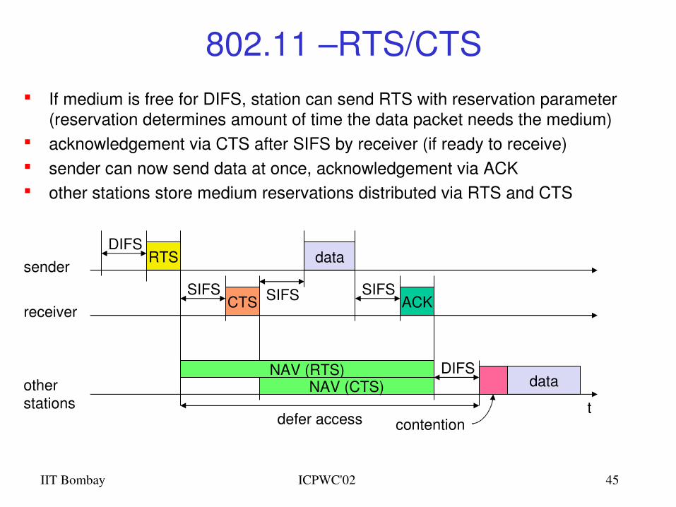
802.11 –RTS/CTS If medium is free for DIFS, station can send RTS with reservation parameter
(reservation determines amount of time the data packet needs the medium) acknowledgement via CTS after SIFS by receiver (if ready to receive) sender can now send data at once, acknowledgement via ACK other stations store medium reservations distributed via RTS and CTS
t
SIFS
DIFS
data
ACK
defer access
otherstations
receiver
senderdata
DIFS
contention
RTS
CTSSIFS SIFS
NAV (RTS)NAV (CTS)
IIT Bombay ICPWC'02 46
802.11 Carrier Sensing
In IEEE 802.11, carrier sensing is performed – at the air interface (physical carrier sensing), and– at the MAC layer (virtual carrier sensing)
Physical carrier sensing – detects presence of other users by analyzing all detected
packets – Detects activity in the channel via relative signal strength
from other sources Virtual carrier sensing is done by sending MPDU duration
information in the header of RTS/CTS and data frames Channel is busy if either mechanisms indicate it to be Duration field indicates the amount of time (in microseconds)
required to complete frame transmission Stations in the BSS use the information in the duration field to
adjust their network allocation vector (NAV)
IIT Bombay ICPWC'02 47
802.11 Collision Avoidance If medium is not free during DIFS time.. Go into Collision Avoidance: Once channel becomes
idle, wait for DIFS time plus a randomly chosen backoff time before attempting to transmit
For DCF the backoff is chosen as follows:– When first transmitting a packet, choose a backoff interval
in the range [0,cw]; cw is contention window, nominally 31– Count down the backoff interval when medium is idle– Countdown is suspended if medium becomes busy– When backoff interval reaches 0, transmit RTS– If collision, then double the cw up to a maximum of 1024
Time spent counting down backoff intervals is part of MAC overhead
IIT Bombay ICPWC'02 48
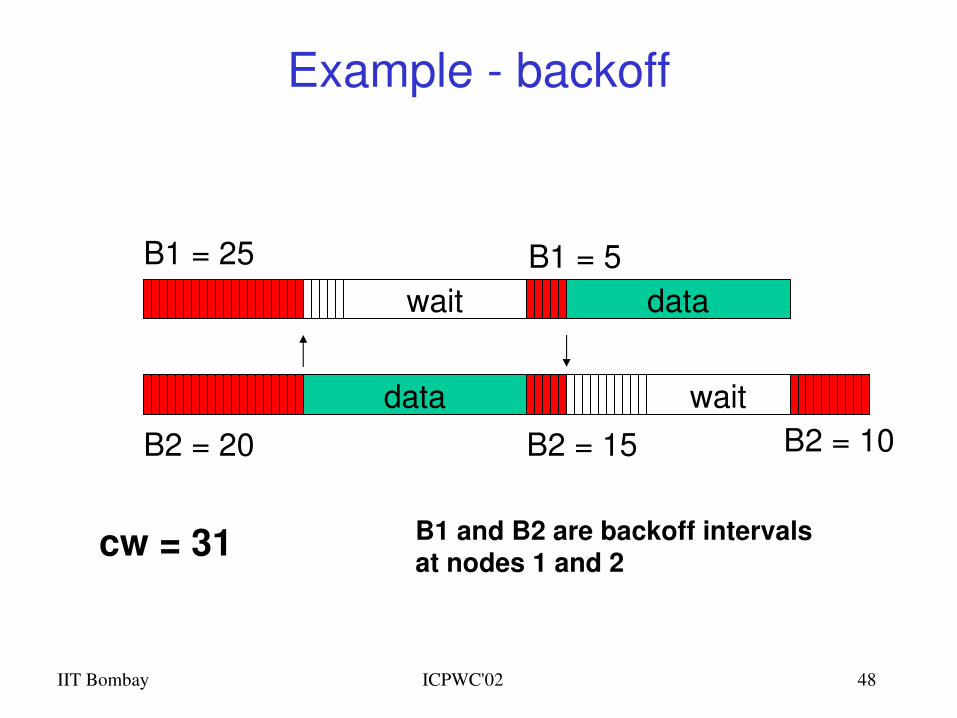
Example backoff
data
waitB1 = 5
B2 = 15
B1 = 25
B2 = 20
data
wait
B1 and B2 are backoff intervalsat nodes 1 and 2cw = 31
B2 = 10
IIT Bombay ICPWC'02 49
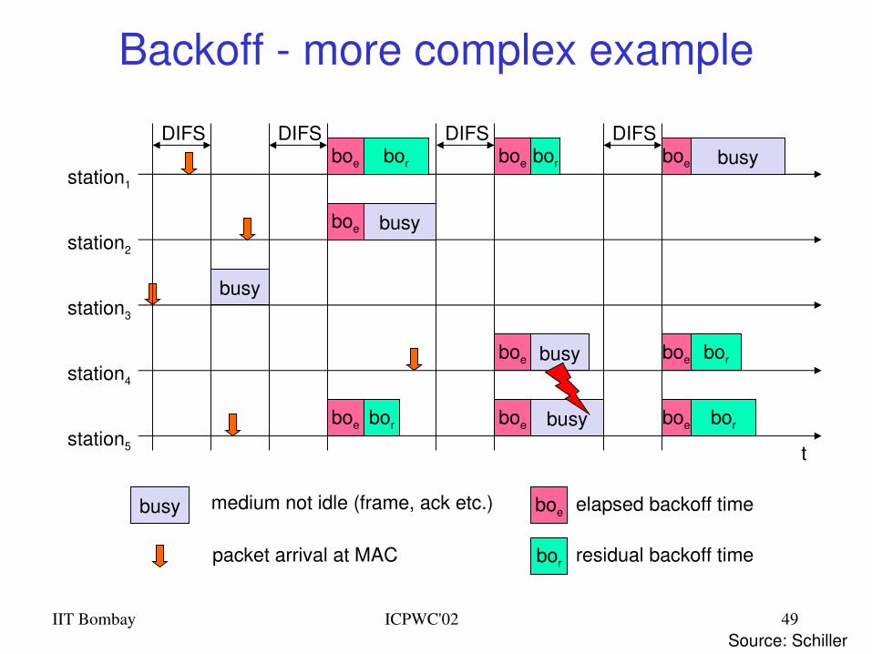
Backoff more complex example
t
busy
boe
station1
station2
station3
station4
station5
packet arrival at MAC
DIFSboe
boe
boe
busy
elapsed backoff time
bor residual backoff time
busy medium not idle (frame, ack etc.)
bor
bor
DIFS
boe
boe
boe bor
DIFS
busy
busy
DIFSboe busy
boe
boe
bor
bor
Source: Schiller
IIT Bombay ICPWC'02 50
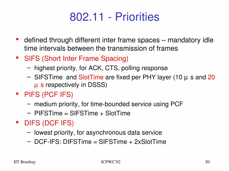
802.11 Priorities
defined through different inter frame spaces – mandatory idle time intervals between the transmission of frames
SIFS (Short Inter Frame Spacing)– highest priority, for ACK, CTS, polling response– SIFSTime and SlotTime are fixed per PHY layer (10 µ s and 20
µ s respectively in DSSS) PIFS (PCF IFS)
– medium priority, for timebounded service using PCF– PIFSTime = SIFSTime + SlotTime
DIFS (DCF IFS)– lowest priority, for asynchronous data service– DCFIFS: DIFSTime = SIFSTime + 2xSlotTime
IIT Bombay ICPWC'02 51
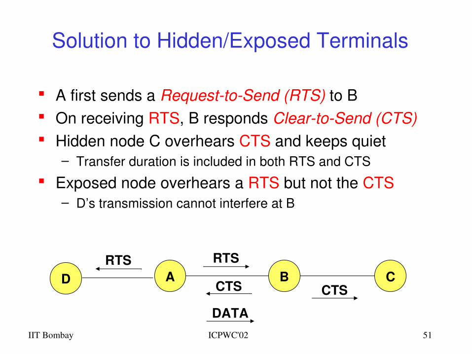
Solution to Hidden/Exposed Terminals
A first sends a RequesttoSend (RTS) to B On receiving RTS, B responds CleartoSend (CTS) Hidden node C overhears CTS and keeps quiet
– Transfer duration is included in both RTS and CTS
Exposed node overhears a RTS but not the CTS– D’s transmission cannot interfere at B
A B CRTS
CTS CTS
DATA
DRTS
IIT Bombay ICPWC'02 52
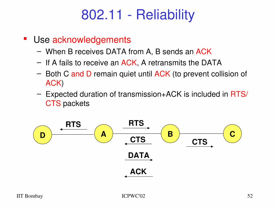
802.11 Reliability
Use acknowledgements– When B receives DATA from A, B sends an ACK– If A fails to receive an ACK, A retransmits the DATA– Both C and D remain quiet until ACK (to prevent collision of
ACK)– Expected duration of transmission+ACK is included in RTS/
CTS packets
A B CRTS
CTS CTS
DATA
DRTS
ACK
IIT Bombay ICPWC'02 53
802.11 Congestion Control
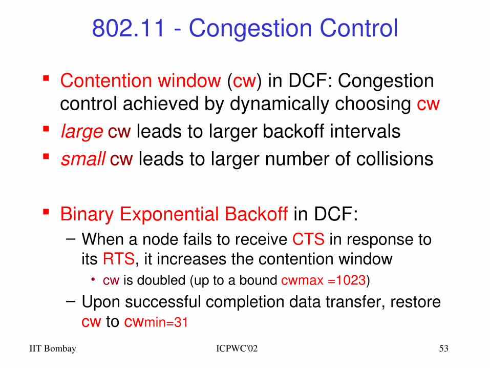
Contention window (cw) in DCF: Congestion control achieved by dynamically choosing cw
large cw leads to larger backoff intervals small cw leads to larger number of collisions
Binary Exponential Backoff in DCF:– When a node fails to receive CTS in response to
its RTS, it increases the contention window• cw is doubled (up to a bound cwmax =1023)
– Upon successful completion data transfer, restore cw to cwmin=31
IIT Bombay ICPWC'02 54
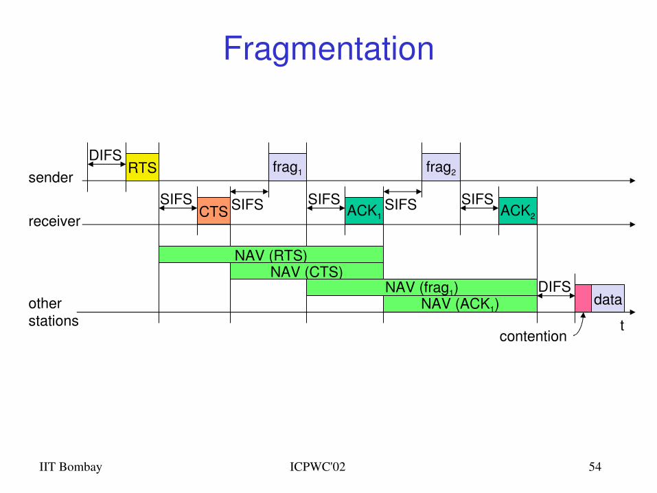
Fragmentation
t
SIFS
DIFS
data
ACK1
otherstations
receiver
senderfrag1
DIFS
contention
RTS
CTSSIFS SIFS
NAV (RTS)NAV (CTS)
NAV (frag1)NAV (ACK1)
SIFSACK2
frag2
SIFS
IIT Bombay ICPWC'02 55
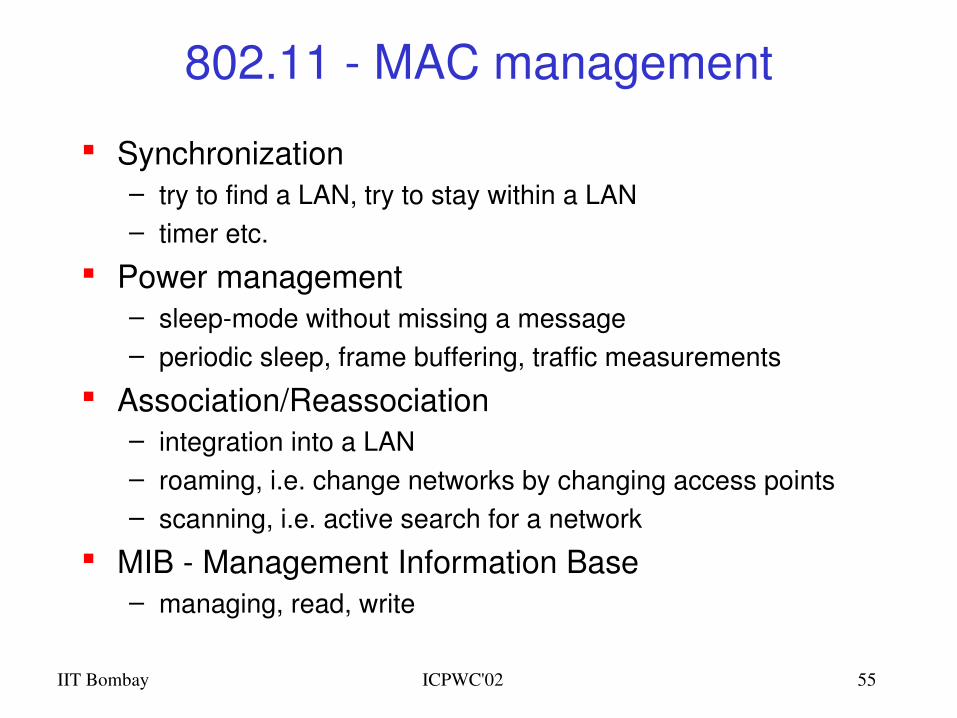
802.11 MAC management
Synchronization– try to find a LAN, try to stay within a LAN– timer etc.
Power management– sleepmode without missing a message– periodic sleep, frame buffering, traffic measurements
Association/Reassociation– integration into a LAN– roaming, i.e. change networks by changing access points – scanning, i.e. active search for a network
MIB Management Information Base– managing, read, write
IIT Bombay ICPWC'02 56
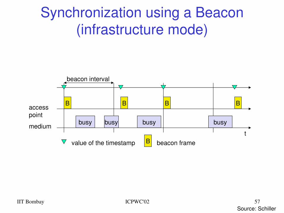
802.11 Synchronization
All STAs within a BSS are synchronized to a common clock – Infrastructure mode: AP is the timing master
• periodically transmits Beacon frames containing Timing Synchronization function (TSF)
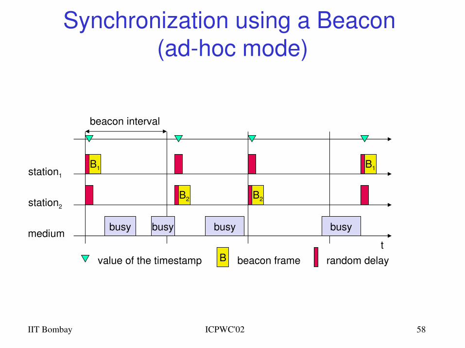
• Receiving stations accepts the timestamp value in TSF– Ad hoc mode: TSF implements a distributed algorithm
• Each station adopts the timing received from any beacon that has TSF value later than its own TSF timer
This mechanism keeps the synchronization of the TSF timers in a BSS to within 4 µ s plus the maximum propagation delay of the PHY layer
IIT Bombay ICPWC'02 57
Synchronization using a Beacon (infrastructure mode)
beacon interval
tmedium
accesspoint
busy
B
busy busy busy
B B B
value of the timestamp B beacon frame
Source: Schiller
IIT Bombay ICPWC'02 58
Synchronization using a Beacon (adhoc mode)
tmedium
station1
busy
B1
beacon interval
busy busy busy
B1
value of the timestamp B beacon frame
station2
B2 B2
random delay
IIT Bombay ICPWC'02 59
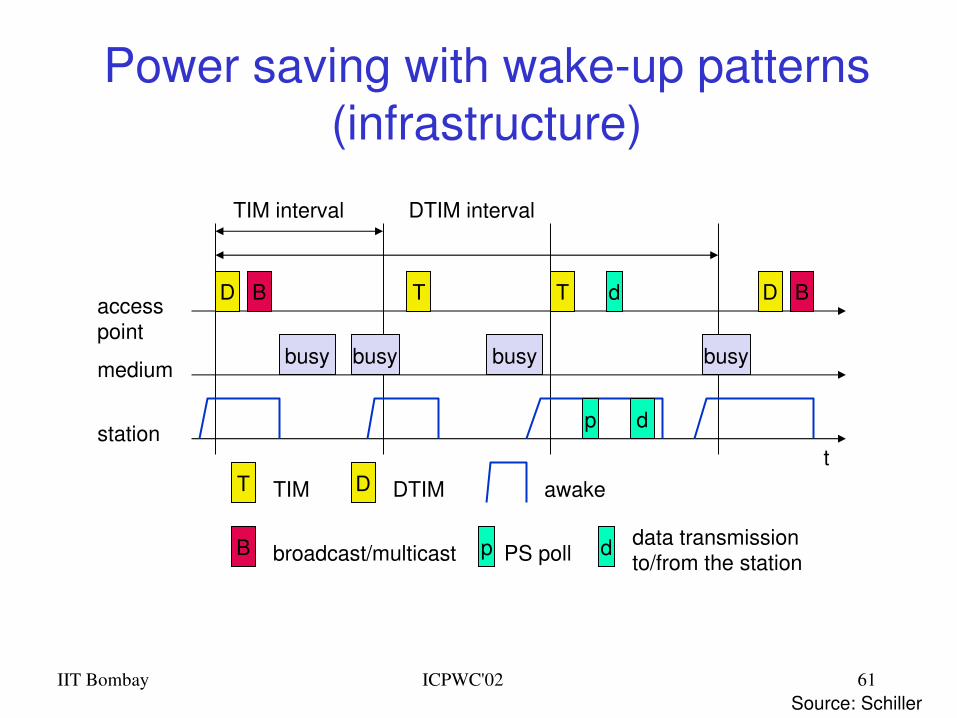
802.11 Power management Idea: switch the transceiver off if not needed States of a station: sleep and awake Timing Synchronization Function (TSF)
– stations wake up at the same time Infrastructure
– Traffic Indication Map (TIM)• list of unicast receivers transmitted by AP
– Delivery Traffic Indication Map (DTIM)• list of broadcast/multicast receivers transmitted by AP
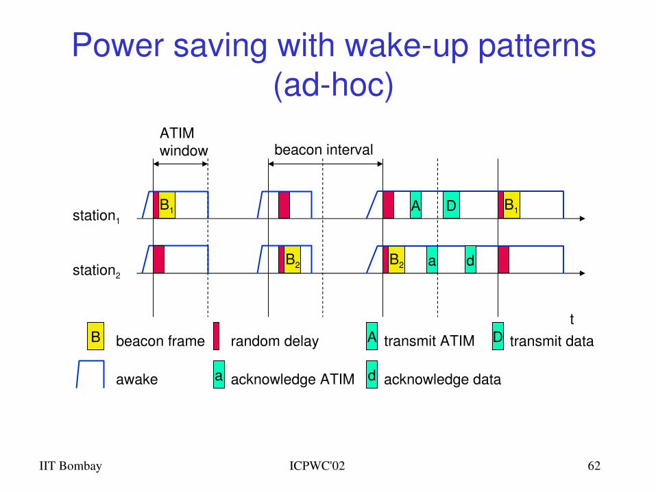
Adhoc– Adhoc Traffic Indication Map (ATIM)
• announcement of receivers by stations buffering frames• more complicated no central AP• collision of ATIMs possible (scalability?)
IIT Bombay ICPWC'02 60
802.11 Energy Conservation
Power Saving in infrastructure mode– Nodes can go into sleep or standby mode– An Access Point periodically transmits a beacon
indicating which nodes have packets waiting for them– Each power saving (PS) node wakes up periodically
to receive the beacon– If a node has a packet waiting, then it sends a PS
Poll• After waiting for a backoff interval in [0,CWmin]
– Access Point sends the data in response to PSpoll
IIT Bombay ICPWC'02 61
Power saving with wakeup patterns (infrastructure)
TIM interval
t
medium
accesspoint
busy
D
busy busy busy
T T D
T TIM D DTIM
DTIM interval
BB
B broadcast/multicast
station
awake
p PS poll
p
d
d
d data transmissionto/from the station
Source: Schiller
IIT Bombay ICPWC'02 62
Power saving with wakeup patterns (adhoc)
awake
A transmit ATIM D transmit datat
station1
B1 B1
B beacon frame
station2
B2 B2
random delay
A
a
D
d
ATIMwindow beacon interval
a acknowledge ATIM d acknowledge data
IIT Bombay ICPWC'02 63
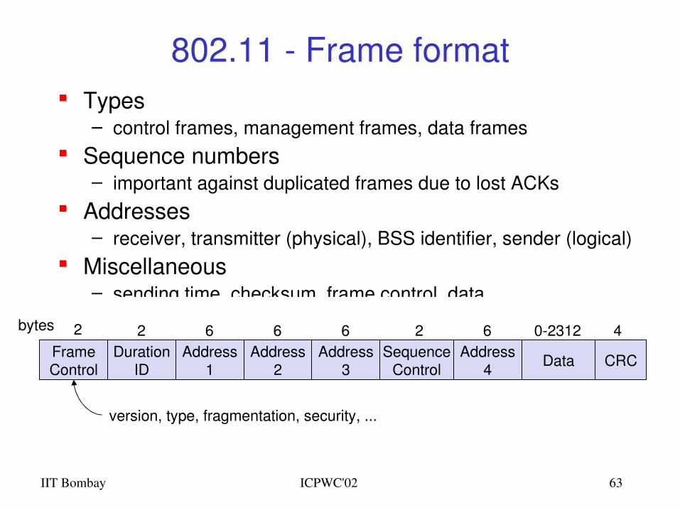
802.11 Frame format Types
– control frames, management frames, data frames Sequence numbers
– important against duplicated frames due to lost ACKs Addresses
– receiver, transmitter (physical), BSS identifier, sender (logical) Miscellaneous
– sending time, checksum, frame control, data
FrameControl
DurationID
Address1
Address2
Address3
SequenceControl
Address4 Data CRC
2 2 6 6 6 62 402312bytes
version, type, fragmentation, security, ...
IIT Bombay ICPWC'02 64
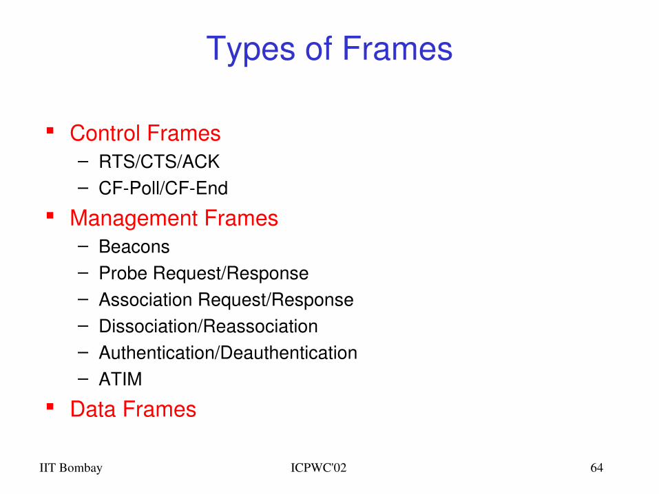
Types of Frames
Control Frames– RTS/CTS/ACK– CFPoll/CFEnd
Management Frames– Beacons– Probe Request/Response– Association Request/Response– Dissociation/Reassociation– Authentication/Deauthentication– ATIM
Data Frames
IIT Bombay ICPWC'02 65
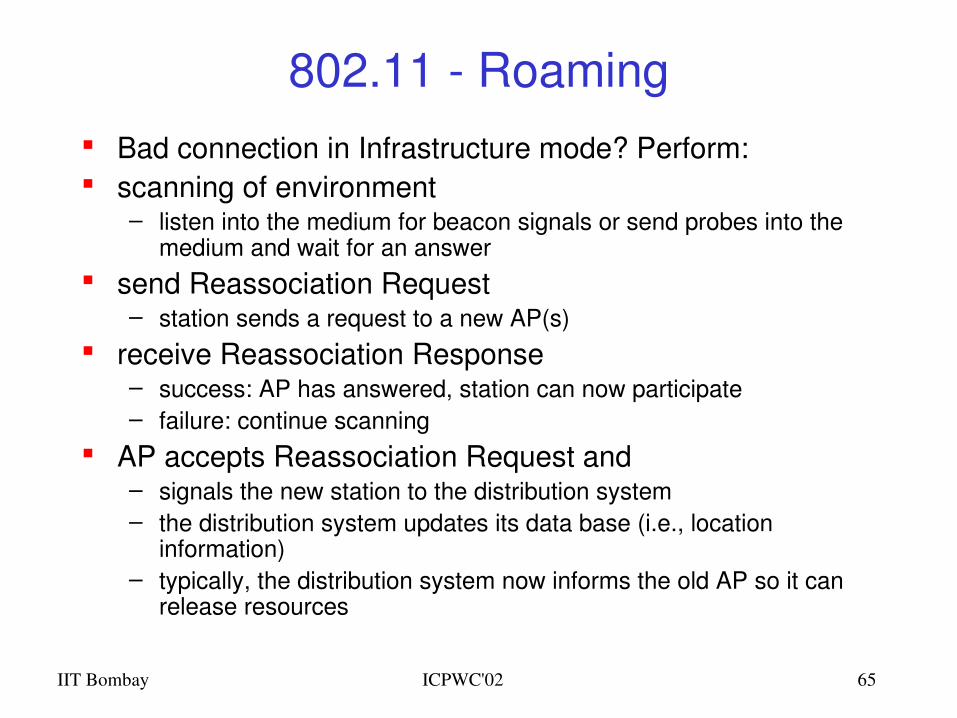
802.11 Roaming Bad connection in Infrastructure mode? Perform: scanning of environment
– listen into the medium for beacon signals or send probes into the medium and wait for an answer
send Reassociation Request– station sends a request to a new AP(s)
receive Reassociation Response– success: AP has answered, station can now participate– failure: continue scanning
AP accepts Reassociation Request and– signals the new station to the distribution system– the distribution system updates its data base (i.e., location
information)– typically, the distribution system now informs the old AP so it can
release resources
802.11based Wireless LANsPoint Coordination Function (PCF)
IIT Bombay ICPWC'02 67
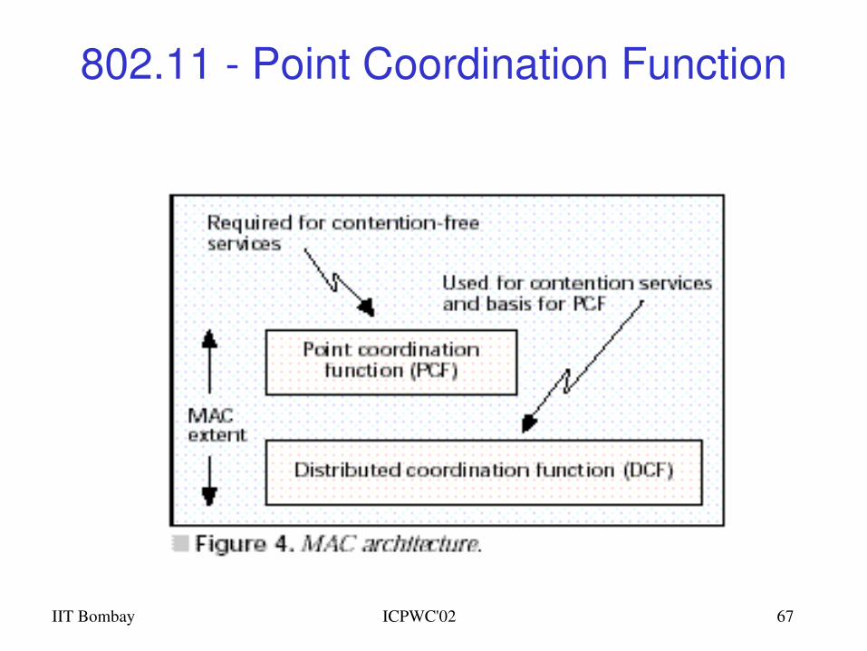
802.11 Point Coordination Function
IIT Bombay ICPWC'02 68
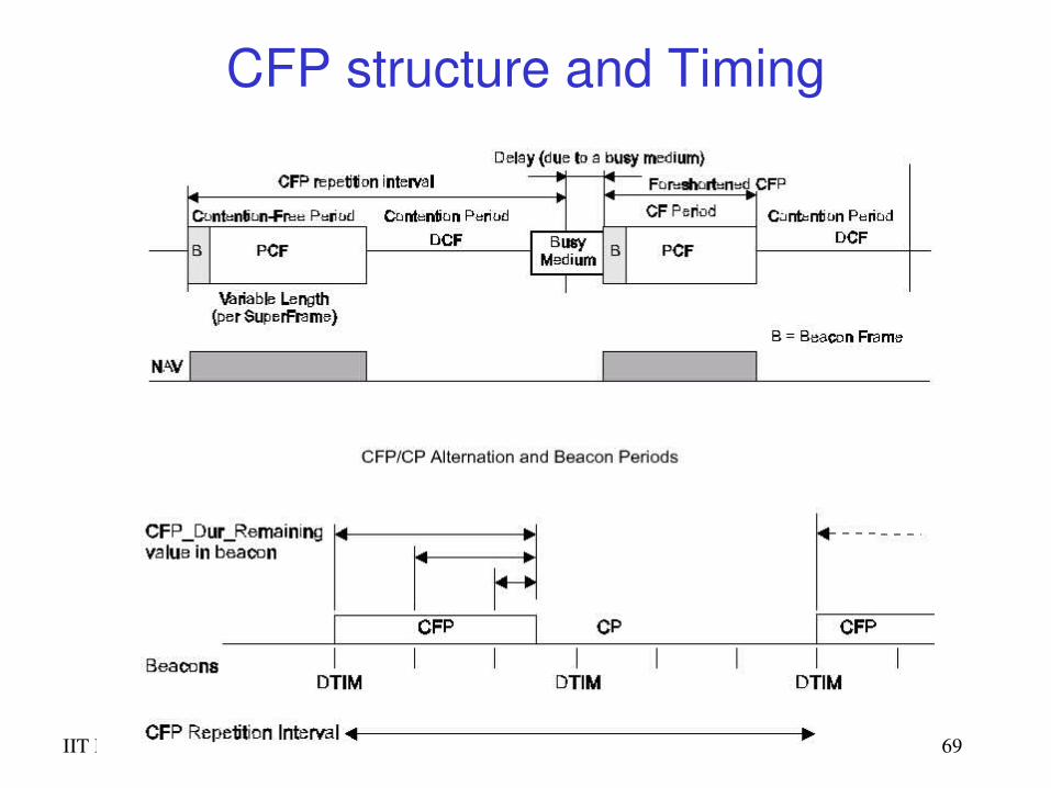
Coexistence of PCF and DCF A Point Coordinator (PC) resides in the Access Point and
controls frame transfers during a Contention Free Period (CFP)
A CFPoll frame is used by the PC to invite a station to send data. Stations are polled from a list maintained by the PC
The CFP alternates with a Contention Period (CP) in which data transfers happen as per the rules of DCF
This CP must be large enough to send at least one maximumsized packet including RTS/CTS/ACK
CFPs are generated at the CFP repetition rate The PC sends Beacons at regular intervals and at the
start of each CFP The CFEnd frame signals the end of the CFP
IIT Bombay ICPWC'02 69
CFP structure and Timing
IIT Bombay ICPWC'02 70
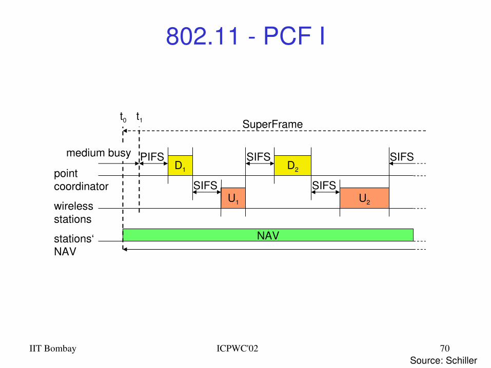
802.11 PCF I
PIFS
stations‘NAV
wirelessstations
point coordinator
D1
U1
SIFS
NAV
SIFSD2
U2
SIFS
SIFS
SuperFramet0
medium busy
t1
Source: Schiller
IIT Bombay ICPWC'02 71
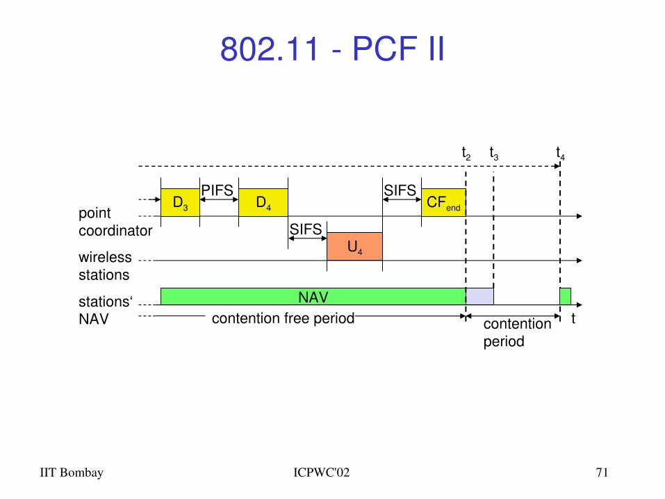
802.11 PCF II
tstations‘NAV
wirelessstations
point coordinator
D3
NAV
PIFSD4
U4
SIFS
SIFSCFend
contentionperiod
contention free period
t2 t3 t4
IIT Bombay ICPWC'02 72
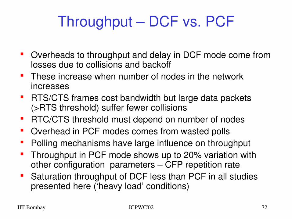
Throughput – DCF vs. PCF
Overheads to throughput and delay in DCF mode come from losses due to collisions and backoff
These increase when number of nodes in the network increases
RTS/CTS frames cost bandwidth but large data packets (>RTS threshold) suffer fewer collisions
RTC/CTS threshold must depend on number of nodes Overhead in PCF modes comes from wasted polls Polling mechanisms have large influence on throughput Throughput in PCF mode shows up to 20% variation with
other configuration parameters – CFP repetition rate Saturation throughput of DCF less than PCF in all studies
presented here (‘heavy load’ conditions)
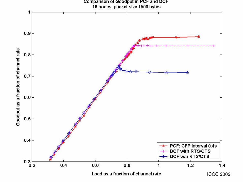
IIT Bombay ICPWC'02 73ICCC 2002
IIT Bombay ICPWC'02 74
IEEE 802.11 Summary Infrastructure and ad hoc modes using DCF Carrier Sense Multiple Access Binary exponential backoff for collision avoidance and
congestion control Acknowledgements for reliability Power save mode for energy conservation Timebound service using PCF Signaling packets for avoiding Exposed/Hidden
terminal problems, and for reservation– Medium is reserved for the duration of the transmission– RTSCTS in DCF– Polls in PCF
IIT Bombay ICPWC'02 75
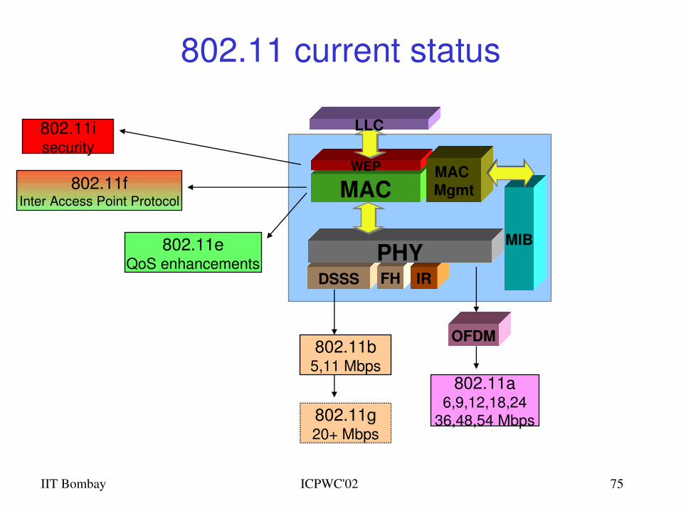
802.11 current status
MAC
MIB
DSSS FH IRPHY
WEP
LLC
MAC Mgmt
802.11b5,11 Mbps
802.11g20+ Mbps
802.11a6,9,12,18,24
36,48,54 Mbps
OFDM
802.11isecurity
802.11fInter Access Point Protocol
802.11eQoS enhancements
Mobile IP
IIT Bombay ICPWC'02 77
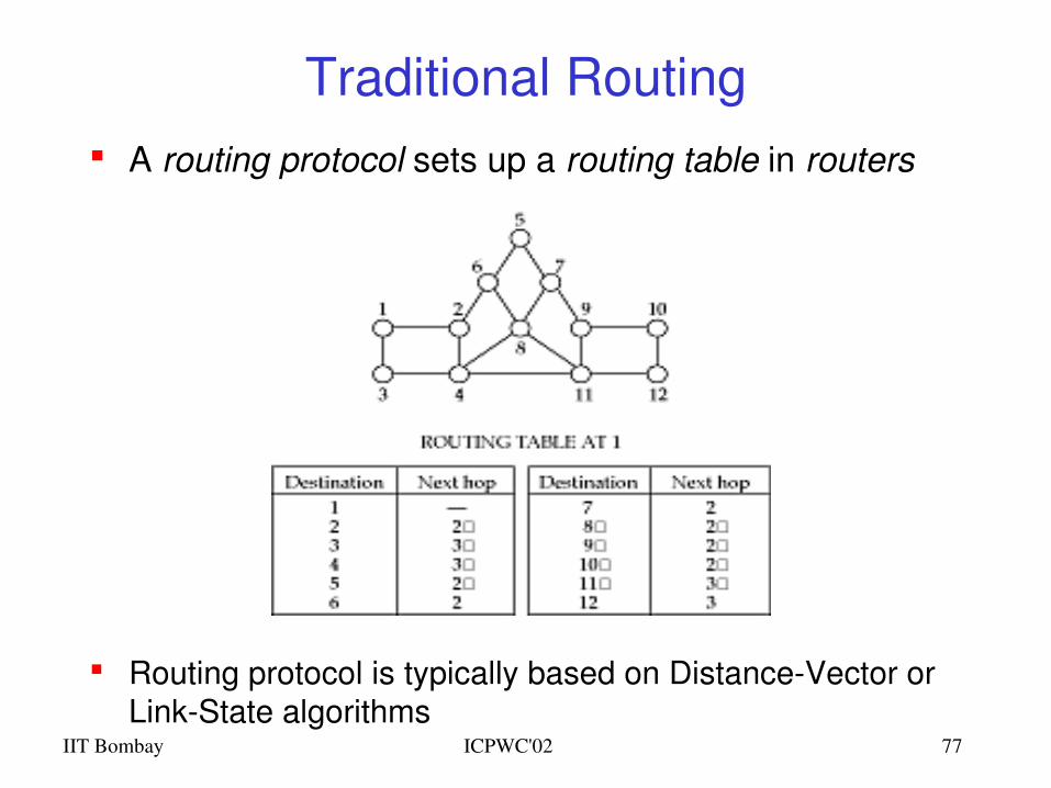
Traditional Routing A routing protocol sets up a routing table in routers
Routing protocol is typically based on DistanceVector or LinkState algorithms
IIT Bombay ICPWC'02 78
Routing and Mobility
Finding a path from a source to a destination
Issues– Frequent route changes
• amount of data transferred between route changes may be much smaller than traditional networks
– Route changes may be related to host movement– Low bandwidth links
Goal of routing protocols– decrease routingrelated overhead– find short routes– find “stable” routes (despite mobility)
IIT Bombay ICPWC'02 79
Mobile IP (RFC 3344): Motivation Traditional routing
– based on IP address; network prefix determines the subnet– change of physical subnet implies
• change of IP address (conform to new subnet), or• special routing table entries to forward packets to new subnet
Changing of IP address– DNS updates take to long time– TCP connections break– security problems
Changing entries in routing tables– does not scale with the number of mobile hosts and frequent
changes in the location– security problems
Solution requirements– retain same IP address, use same layer 2 protocols– authentication of registration messages, …
IIT Bombay ICPWC'02 80
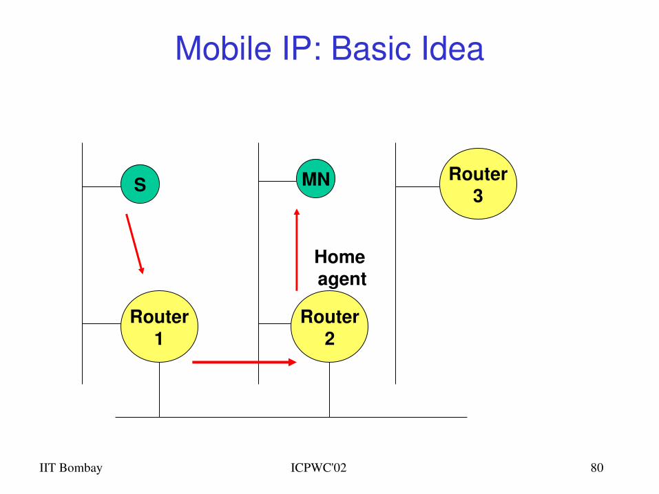
Mobile IP: Basic Idea
Router1
Router3
Router2
S MN
Home agent
IIT Bombay ICPWC'02 81
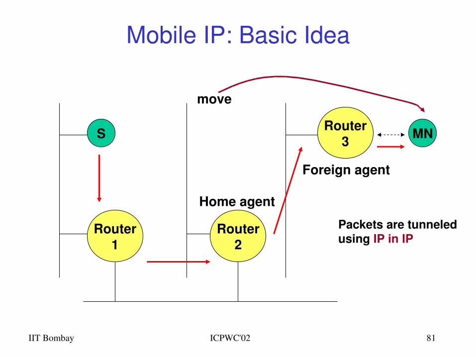
Mobile IP: Basic Idea
Router1
Router3
Router2
S MN
Home agent
Foreign agent
move
Packets are tunneledusing IP in IP
IIT Bombay ICPWC'02 82
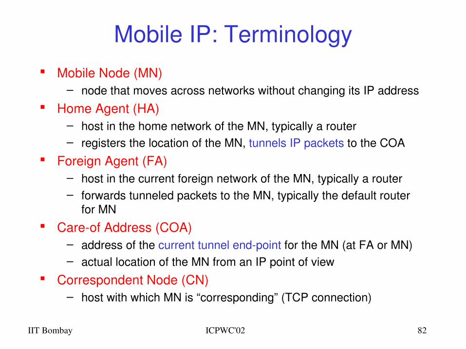
Mobile IP: Terminology Mobile Node (MN)
– node that moves across networks without changing its IP address Home Agent (HA)
– host in the home network of the MN, typically a router– registers the location of the MN, tunnels IP packets to the COA
Foreign Agent (FA)– host in the current foreign network of the MN, typically a router– forwards tunneled packets to the MN, typically the default router
for MN Careof Address (COA)
– address of the current tunnel endpoint for the MN (at FA or MN)– actual location of the MN from an IP point of view
Correspondent Node (CN)– host with which MN is “corresponding” (TCP connection)
IIT Bombay ICPWC'02 83
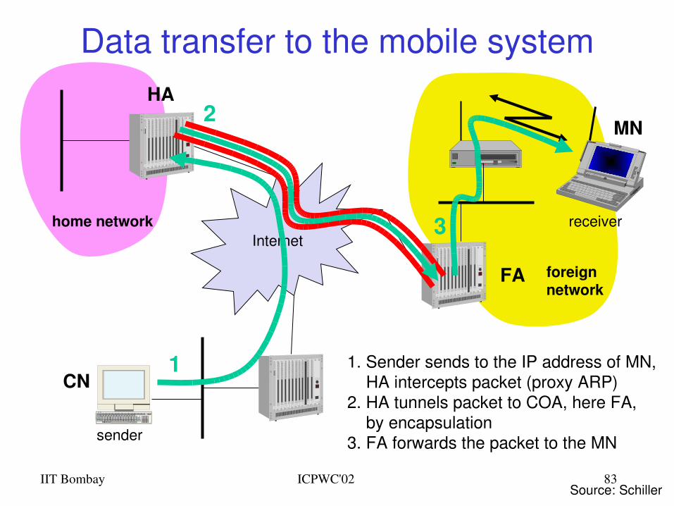
Data transfer to the mobile system
Internet
sender
FA
HA
MN
home network
foreignnetwork
receiver
1
2
3
1. Sender sends to the IP address of MN, HA intercepts packet (proxy ARP)2. HA tunnels packet to COA, here FA, by encapsulation3. FA forwards the packet to the MN
Source: Schiller
CN
IIT Bombay ICPWC'02 84
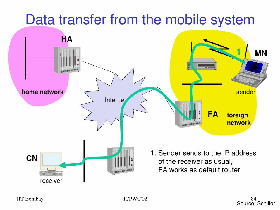
Data transfer from the mobile system
Internet
receiver
FA
HA
MN
home network
foreignnetwork
sender
1
1. Sender sends to the IP address of the receiver as usual, FA works as default router
Source: Schiller
CN
IIT Bombay ICPWC'02 85
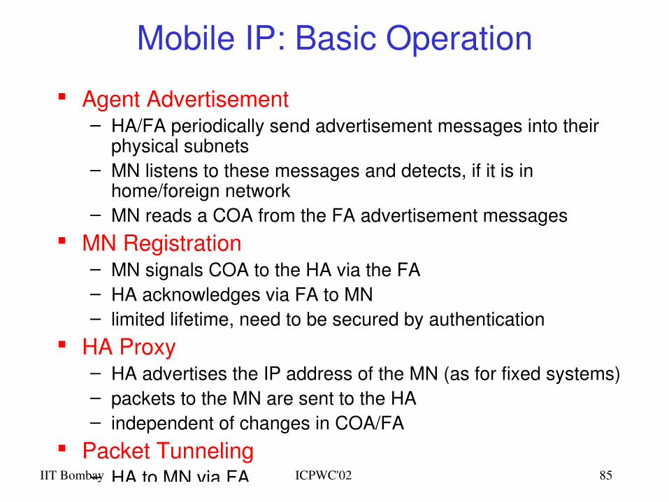
Mobile IP: Basic Operation
Agent Advertisement– HA/FA periodically send advertisement messages into their
physical subnets– MN listens to these messages and detects, if it is in
home/foreign network– MN reads a COA from the FA advertisement messages
MN Registration – MN signals COA to the HA via the FA– HA acknowledges via FA to MN– limited lifetime, need to be secured by authentication
HA Proxy– HA advertises the IP address of the MN (as for fixed systems) – packets to the MN are sent to the HA – independent of changes in COA/FA
Packet Tunneling– HA to MN via FA
IIT Bombay ICPWC'02 86
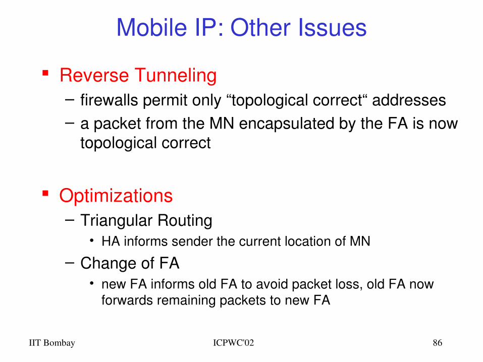
Mobile IP: Other Issues
Reverse Tunneling– firewalls permit only “topological correct“ addresses– a packet from the MN encapsulated by the FA is now
topological correct
Optimizations– Triangular Routing
• HA informs sender the current location of MN
– Change of FA• new FA informs old FA to avoid packet loss, old FA now
forwards remaining packets to new FA
IIT Bombay ICPWC'02 87
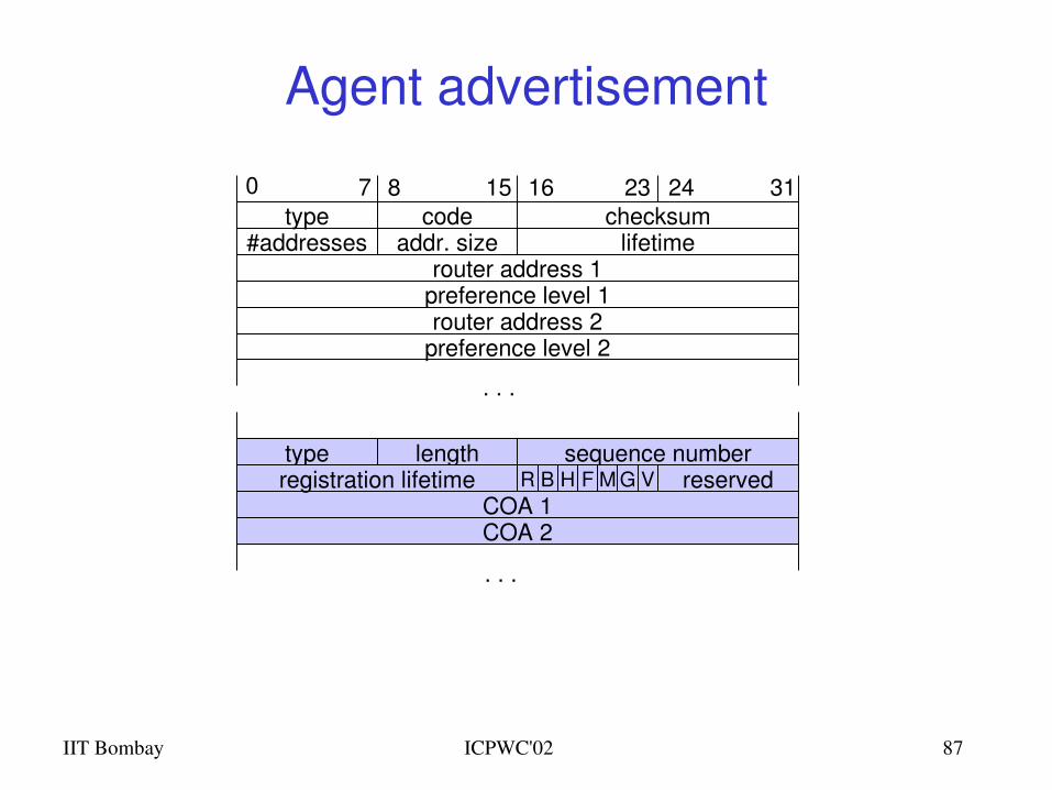
Agent advertisement
preference level 1router address 1
#addressestype
addr. size lifetimechecksum
COA 1COA 2
type sequence numberlength
0 7 8 15 16 312423code
preference level 2router address 2
. . .
registration lifetime
. . .
R B H F M G V reserved
IIT Bombay ICPWC'02 88
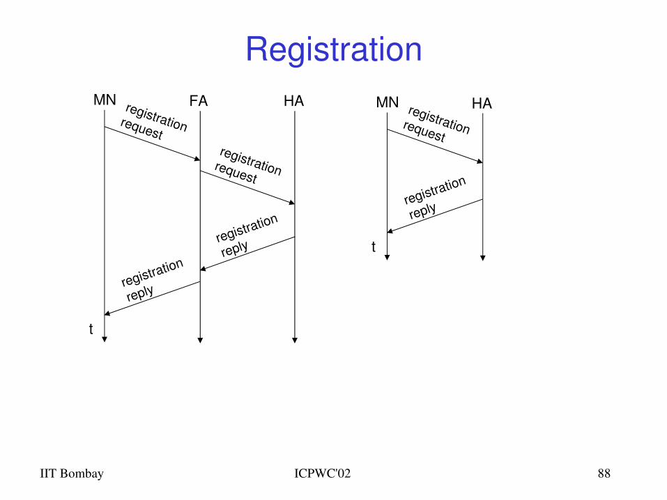
Registration
t
MN HAregistrationrequest
registration
reply
t
MN FA HAregistrationrequestregistrationrequest
registration
reply
registration
reply
IIT Bombay ICPWC'02 89
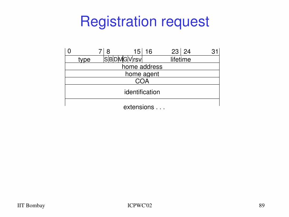
Registration request
home agenthome address
type lifetime0 7 8 15 16 312423
rsv
identification
COA
extensions . . .
S B DMGV
IIT Bombay ICPWC'02 90
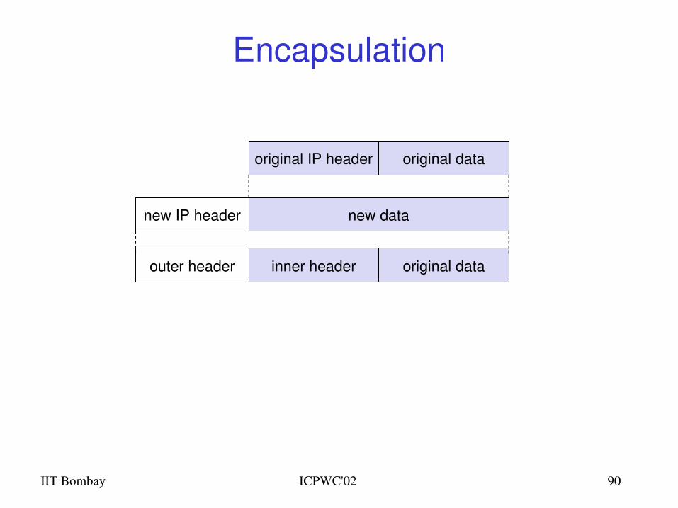
Encapsulation
original IP header original data
new datanew IP header
outer header inner header original data
IIT Bombay ICPWC'02 91
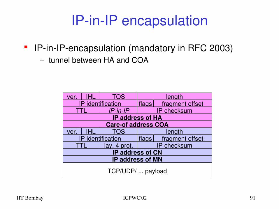
IPinIP encapsulation
IPinIPencapsulation (mandatory in RFC 2003)– tunnel between HA and COA
Careof address COAIP address of HA
TTLIP identification
IPinIP IP checksumflags fragment offset
lengthTOSver. IHL
IP address of MNIP address of CN
TTLIP identification
lay. 4 prot. IP checksumflags fragment offset
lengthTOSver. IHL
TCP/UDP/ ... payload
IIT Bombay ICPWC'02 92
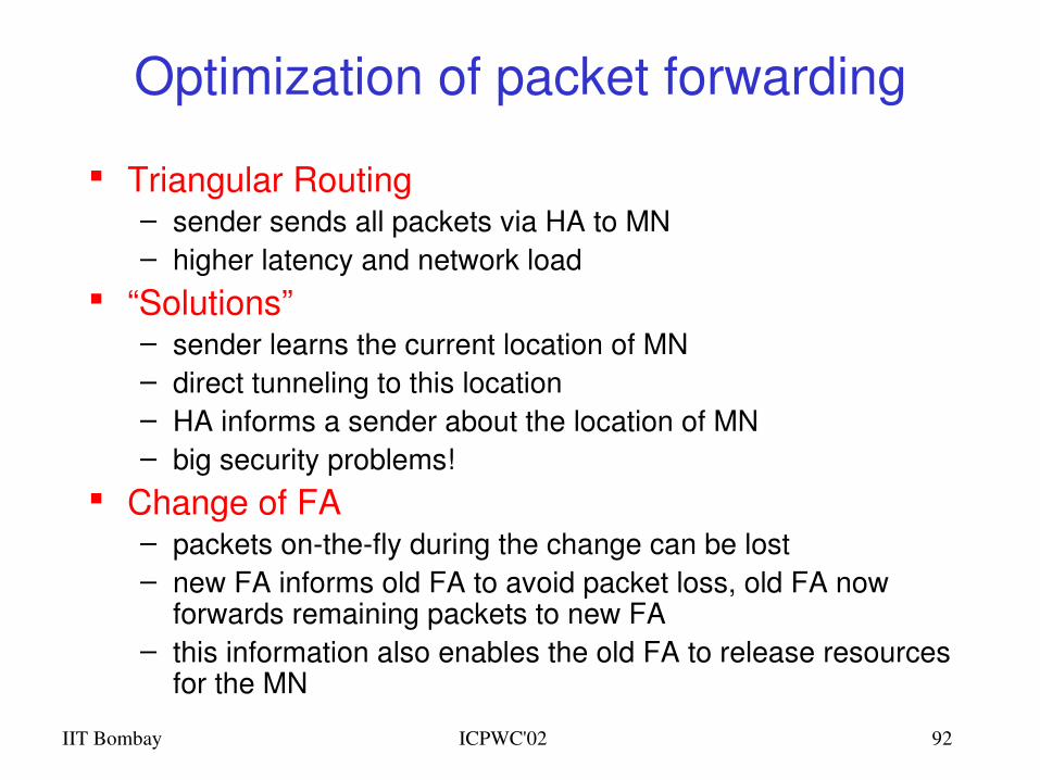
Optimization of packet forwarding
Triangular Routing– sender sends all packets via HA to MN– higher latency and network load
“Solutions”– sender learns the current location of MN– direct tunneling to this location– HA informs a sender about the location of MN– big security problems!
Change of FA– packets onthefly during the change can be lost– new FA informs old FA to avoid packet loss, old FA now
forwards remaining packets to new FA– this information also enables the old FA to release resources
for the MN
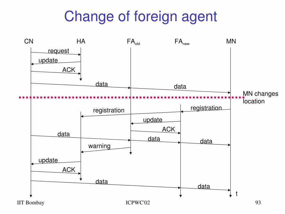
IIT Bombay ICPWC'02 93
Change of foreign agent
CN HA FAold FAnew MN
t
requestupdate
ACK
data dataMN changeslocation
registration
updateACK
datadata data
warning
updateACK
datadata
registration
IIT Bombay ICPWC'02 94
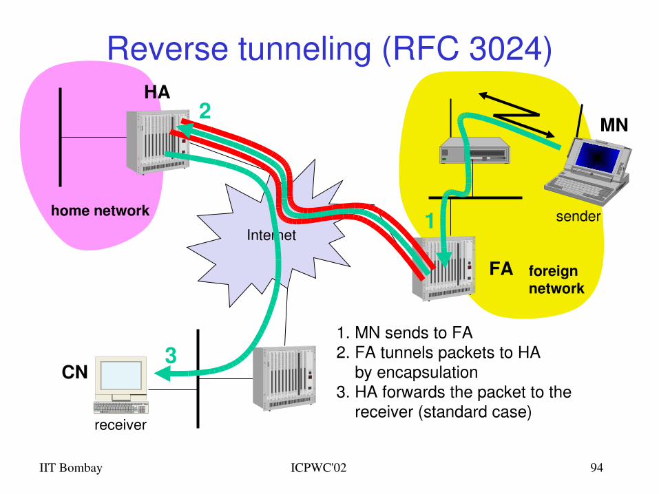
Reverse tunneling (RFC 3024)
Internet
receiver
FA
HA
MN
home network
foreignnetwork
sender
3
2
1
1. MN sends to FA2. FA tunnels packets to HA by encapsulation3. HA forwards the packet to the receiver (standard case)
CN
IIT Bombay ICPWC'02 95
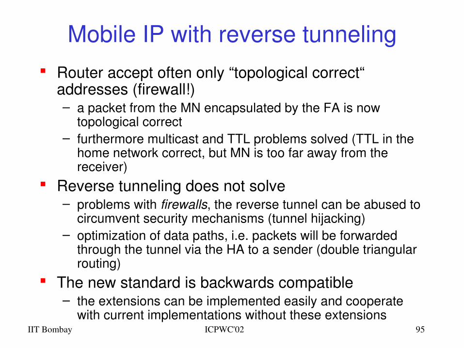
Mobile IP with reverse tunneling Router accept often only “topological correct“
addresses (firewall!)– a packet from the MN encapsulated by the FA is now
topological correct– furthermore multicast and TTL problems solved (TTL in the
home network correct, but MN is too far away from the receiver)
Reverse tunneling does not solve– problems with firewalls, the reverse tunnel can be abused to
circumvent security mechanisms (tunnel hijacking)– optimization of data paths, i.e. packets will be forwarded
through the tunnel via the HA to a sender (double triangular routing)
The new standard is backwards compatible– the extensions can be implemented easily and cooperate
with current implementations without these extensions
IIT Bombay ICPWC'02 96
Mobile IPv4 Summary
Mobile node moves to new location Agent Advertisement by foreign agent Registration of mobile node with home agent Proxying by home agent for mobile node Encapsulation of packets Tunneling by home agent to mobile node via
foreign agent
Optimizations for triangular routing Reverse tunneling
IIT Bombay ICPWC'02 97
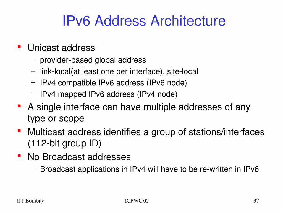
IPv6 Address Architecture
Unicast address – providerbased global address– linklocal(at least one per interface), sitelocal– IPv4 compatible IPv6 address (IPv6 node)– IPv4 mapped IPv6 address (IPv4 node)
A single interface can have multiple addresses of any type or scope
Multicast address identifies a group of stations/interfaces (112bit group ID)
No Broadcast addresses– Broadcast applications in IPv4 will have to be rewritten in IPv6
IIT Bombay ICPWC'02 98
Autoconfiguration
Plug & Play a machine when plugged in will automatically discover and register the required parameters for Internet connectivity
Autoconfiguration includes– creating a linklocal address– verifying its uniqueness on a link– determining what information should be
autoconfigured, addresses and/or other info– In the case of addresses, they may be obtained
through stateless or stateful mechanism (DHCPv6), or both
IIT Bombay ICPWC'02 99
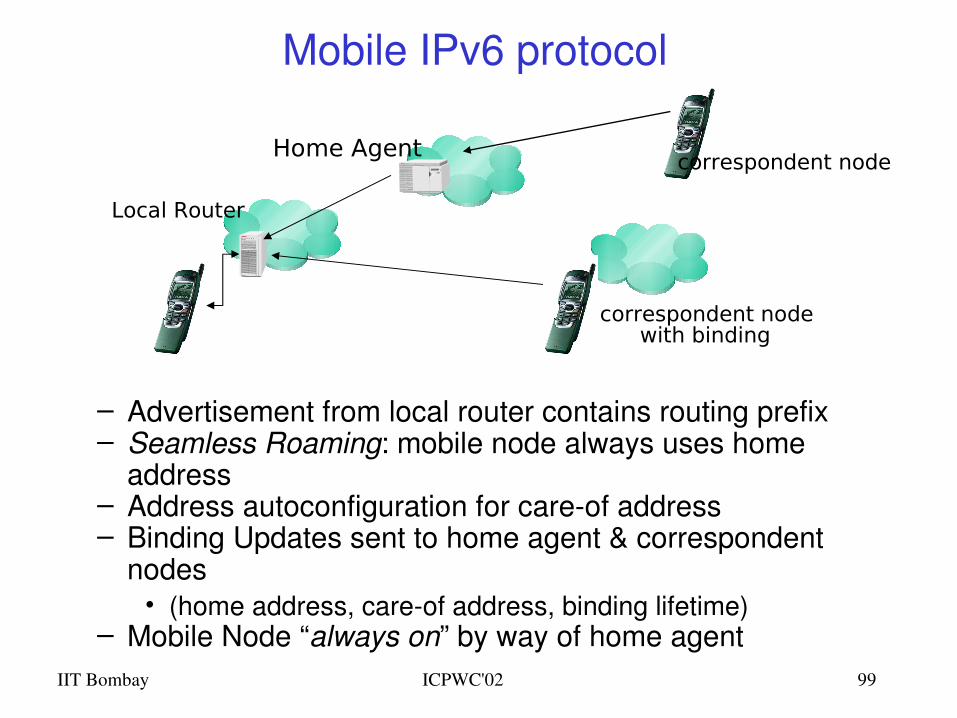
Mobile IPv6 protocol
– Advertisement from local router contains routing prefix– Seamless Roaming: mobile node always uses home
address– Address autoconfiguration for careof address– Binding Updates sent to home agent & correspondent
nodes• (home address, careof address, binding lifetime)
– Mobile Node “always on” by way of home agent
Local Router
Home Agent
correspondent nodewith binding
correspondent node
IIT Bombay ICPWC'02 100
IPv6 and Mobile IPv6 Summary
Proliferation of wireless devices driving adoption of IPv6 340 undecillion addresses
– (340,282,366,920,938,463,463,374,607,431,768,211,456) total! Billions of IPaddressable wireless handsets Specially interesting for China which has
– 8 million IPv4 addresses and 50+ million handsets Mobile IP considers the mobility problem as a routing problem
– managing a binding – that is, a dynamic tunnel between a careof address and a home address Binding updates in IPv6 replace registration requests in IPv4
– Of course,there is a lot more to it than that! Mobile IPv6 still hampered by the lack of security solutions
– IPSec requires deployed PKI (not available yet)