Embed Size (px)
Citation preview

GE SmartHome™
Wireless Lighting Control
On/Off/Dim Dimmer Switch
45639 ZW3003
Made in ChinaZ-Wave® Certified Wireless Lighting Control


Introduction:
Thank you for your purchase of a GE Z-Wave® control device. Z-Wave technology is designed to automate lighting/home control and provide easy remote operation of all your Z-Wave enabled devices. The GE Z-Wave product family includes a variety of devices to control lighting in your home. It is up to you whether you want to control one room or your entire house and whether you want to do it all now or start with one room and add more over time.
This dimmer is one component of a Z-Wave® control system and is designed to work with all other Z-Wave enabled devices in a home control network. It will also act as a wireless repeater to insure that commands intended for another device in the network are received, thereby extending the range of the wireless controller. Z-Wave devices of other types and brands can be added to the system and will also act as range extenders if they support this function of repeating the signal received to other nodes in the system.

This device is intended for installation in accordance with the National Electric Code and local regulations in the United States, or the Canadian Electrical Code and local regulations in Canada. If you are unsure or uncomfortable about performing this installation consult a qualified electrician.
CAUTION
This switch is designed for use only with permanently installed incandescent fixtures. Do not use it to control fluorescent lighting, transformer supplied lighting/appliances or receptacles. The incandescent lighting controlled by this dimmer switch must not exceed 600 watts.
NOT FOR USE WITH MEDICAL OR LIFE SUPPORT EQUIPMENT
There are no user serviceable parts in this unit.
Z-Wave enabled devices should never be used to supply power to or control the On/Off status of medical and/or life support equipment!
Dimmer switch
LED light
Air gap switch
RISK OF FIRE
RISK OF ELECTRICAL SHOCK
RISK OF BURNS
WARNING
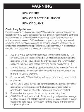
Controlling Appliances:Exercise extreme caution when using Z-Wave devices to control appliances. Operation of the Z-Wave device may be in a different room than the controlled appliance, also an unintentional activation may occur if the wrong button on the remote is pressed. Z-Wave devices may automatically be powered on due to timed event programming. Depending upon the appliance, these unattended or unintentional operations could possibly result in a hazardous condition. For these reasons, we recommend the following:
1. Assign Z-Wave controlled appliances to device numbers 10 – 18 on the GE remote. The likelihood of unintentionally turning on the appliance will be reduced significantly because the “Shift” button will need to be pressed before pressing device numbers 10-18.
2. Z-Wave devices controlling appliances should be removed from “All” control setting. Instructions on how to do this are included in the manual for your GE remote.
3. Do Not include Z-Wave devices in Groups or Scenes if they control appliances.
4. Do Not use Z-Wave devices to control electric heaters or any other appliances which may present a hazardous condition due to unattended or unintentional or automatic power on control.
5. Double check programs for accuracy before using them.6. CAUTION – To reduce the risk of overheating and possible damage
to other equipment, DO NOT install to control a receptacle, a motor-operated appliance, a fluorescent lighting fixture or transformer supplied appliance.

Wireless RangeThis device complies with the Z-Wave standard of open-air, line of sight transmission distances of 65 feet. Actual performance in a home depends on the number of walls between the remote controller and the destination device, the type of construction and the number of Z-Wave enabled devices installed in the control network. Every Z-Wave enabled device acts as a signal repeater and multiple devices result in more possible transmission routes which helps eliminate “RF dead-spots”.
Things to consider regarding RF range:• Each wall or obstacle (i.e.: refrigerator, big screen TV, etc.) between the remote or Z-Wave device and the destination device will reduce the maximum range by approximately 25-30%. • Brick, tile or concrete walls block more of the RF signal than walls made of wooden studs and plasterboard (drywall). • Wall mounted Z-Wave devices installed in metal junction boxes may suffer a significant loss of range (approximately 20%) since the metal box blocks a large part of the RF signal.

Effects of Home Construction on Wireless Range Between Z-Wave Enabled Devices.
Note: The distances shown in the table below are typical examples. Actual performance in your home will vary.
From the Remote (or repeating Z-Wave module) to destination device:
* For Plug-in Modules or In-Wall Devices Installed, Plastic Junction Boxes** Line of Sight / no obstructions
Type of Construction
0**
1Number of Walls or Obstacles 2
3
100’
70’
49’
34’
80’
56’
39’
27’
100’
60’
36’
21’
80’
48’
29’
17’
Wood Frame w/Drywall
Plastic J-Boxes*
Metal J-Boxes
Plastic J-Boxes*
Metal J-Boxes
Brick, Tile or Concrete

Please Note: Z-Wave home control networks are designed to work properly alongside 802.11 wireless computer networks, Bluetooth and 2.4GHz, 5.8GHz or DECT devices. Some baby cams, wireless video devices and older cordless phones using the 900MHz frequency range may cause interference and limit Z-Wave functionality. Many 900MHz products have a switch to select channel “A” or “B”. You may find that one of these channels will cause less interference than the other.
IMPORTANT NOTE ABOUT 3-WAY CIRCUITSThe term “3-way circuit” refers to a circuit with two switches and one load (light) like you find at the top and bottom of a stairway. There are many ways to physically wire a 3-way circuit and it is important to understand how the circuit you wish to upgrade to Z-Wave control is wired. Below is a description of a typical 3-way circuit.One of the ways to wire a two-switch/one-load circuit is to route the incoming power through the first switch, then to the second switch and then to the load. Although very common and by no means a standard, it is the easiest to convert to Z-Wave control. With this type of circuit, Switch 1 is replaced by the Z-Wave auxiliary switch and Switch 2 is replaced with the primary Z-Wave switch. The auxiliary switch does not actually control the power; instead, it sends a momentary voltage signal through the traveler wire to the primary switch which in turn, controls the power to the load.

Other color
White
Z-Wave Auxiliary
Z-Wave Primary
Black
Black (Line / Hot) Black (Line / Hot)
White
White (Neutral)
Black (Load)
White
Z-Wave Primary
Z-Wave Auxiliary
Colored (NOT GREEN)
Black
Black Black
White Switch 1 Switch 2
Typical 3-way circuit:
Wrong Z-Wave switch position for typical 3-way circuit;
Correct Z-Wave switch position for typical 3-way circuit:

Please consult an electrician if you have trouble identifying the type of wiring circuit you wish to convert or if you do not feel confident in your ability to convert the circuit to Z-Wave control.
INSTALLATIONThis dimmer switch may be used in new installations or to replace an existing wall switch. It may be used by itself for 2-way control (one switch & one load), with one 45610 Auxiliary Switch* for 3-way control (two switches & one load) or with two 45610 Auxiliary switches for 4-way control (three switches & one load). When used by itself for 2-way control, please make sure that the screw terminal for the traveler wire is insulated (Do Not Remove the tape over the terminal if you are not using the traveler connection).
Single Switch Wiring Schematic
White (Neutral)
Z-Wave Auxiliary
Z-Wave Primary
Black (Line / Hot)
Black (Load)
Traveler - Colored (Not Green)
Green (Ground)
White (Neutral)
Z-Wave Primary
Black (Line / Hot)
Black (Load)
Green (Ground)
White (Neutral)
Z-Wave Auxiliary
Z-Wave Primary
Black (Line / Hot)
Black (Load)
Traveler - Colored (Not Green)
Green (Ground)
White (Neutral)
Z-Wave Primary
Black (Line / Hot)
Black (Load)
Green (Ground)
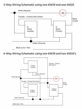
3-Way Wiring Schematic using one 45639 and one 45610
4-Way Wiring Schematic using one 45639 and two 45610’s
Traveler - Colored (Not Green)
White (Neutral)
Z-WaveAuxiliary
Z-WavePrimary
Black (Line / Hot)
Black (Load)
Green (Ground)
Z-Wave 45610
Traveler - Colored (Not Green)
Green (Ground)
Z-WaveAuxiliary

Single, Dual and Triple Gang Boxes
The metal plate surrounding the switch assembly is a heat sink. The maximum load rating (600W) is provided when installed in a single gang box with the full heat sink. Multiple 45639 dimmer switches may be installed in dual or triple gang boxes and, if necessary, one or both sides of the heat sink may be removed by bending it at the score lines. There is a corresponding reduction in the switch’s load rating when ganged. DO NOT exceed the following loads: Dimmer Rating Number of Dimmers Heat Sink
600W One switch in a Single Gang Box Full500W Two switches in a Double Gang Box One side removed400W Three switches in a Triple Gang Box Both sides removed
Traveler
Black (Load)
Black (HOT)
Ground

SHOCK HAZARD! Turn OFF the power to the branch circuit at the circuit breaker in your electrical service panel. Ensure power is OFF before you install this device. All wiring connections must be made with the POWER OFF to avoid personal injury and/or damage to the switch.
WARNING
1. Shut off power to the circuit at fuse box or 15A circuit breaker.
2. Remove wall plate. ! Warning: Verify power is OFF to switch box before continuing.
3. Remove the switch mounting screws.
4. Carefully remove the switch from the switch box. DO NOT disconnect the wires.
5. There are four screw terminals on the 45639 switch; these are marked LINE (Hot), LOAD, GROUND and TRAVELER. The Traveler terminal is only used for 3-way or 4-way wiring and should remain insulated if the 45639 is being installed in a 2-way system (one switch & one load). Match these screw terminals to the wires connected to the existing switch. (Do Not remove the tape over the terminal if you are not using the traveler connection).
6. Disconnect the wires from the existing switch.
7. Connect the green or bare copper ground wire to the GROUND terminal.

8.Connect the black wire that goes to the light to the terminal marked LOAD.
9. Connect the black wire that comes from the electrical service panel (Hot) to the terminal marked LINE. Note: UL specifies that the tightening torque for the screws is 14Kgf-cm.
10. OPTIONAL for 3 or 4-way control: Connect the Traveler wire (usually Red) to the screw terminal marked TRAVELER. The other end of this Traveler wire connects to the TRAVELER screw terminal on the 45610 Auxiliary Switch. See the following section for information about wiring the 45610 Auxiliary Switch.
11. Insert Z-Wave Switch into the switch box being careful not to pinch or crush wires.
12. Secure the switch to the box using the supplied screws.
13. Mount the wall plate.
14. Reapply power to the circuit at fuse box or circuit breaker and test the system.
Optional for 3 or 4-Way Control:1. The 45610 requires the following 3 wiring connections: a. The Traveler wire. This is used to send voltage signals to the primary Z-Wave switch. The signals tell the Z-wave switch what action to perform. b. Ground.c. Neutral. 2. DO NOT connect the 45610 auxiliary switch to the home’s black Hot (Line) wire.

Observe Important Wiring Information Important: This switch is rated for and intended to only be used with copper wire. The home’s electrical wires may be attached to the screw terminals or inserted into the holes in the back of the switch enclosure and clamped in place by tightening the screw terminals. Always follow the recommended wire strip lengths when making wiring connections.Wire strip length:• For attachment to screw terminals: Strip insulation 1” (max 14 AWG wire). • For attachment using the enclosure’s holes: Strip insulation 5/8” (max 14 AWG wire).
You should now be able to use the rocker to manually turn On/Off or adjust the brightness of the connected load.
Use your primary controller to include the switch in the home control network after the switch is wired as shown in the above diagram. It can then be added to groups and/or lighting scenes and managed remotely to control the On/Off/Dim status of the connected lighting.
Air Gap SwitchDuring normal operation, there is a small amount of power passing through the switch to the load even when the switch is turned off. The 45639 has an air gap switch on the lower left side (see diagram for location) to completely disconnect power to the load. Pull the air gap switch OUT to disconnect the power while replacing light bulbs and push it all the way back in for

normal operation. The air gap switch must be all the way in for the switch to function and control the lighting.
Key Features• Remote On/Off/Brightness control via the Z-Wave controller/network• Manual On/Off/Brightness control with the front panel rocker• Compatible with 2, 3, or 4 way wiring configurations• LED indicates switch location in a dark room
BASIC OPERATIONRemote ControlGE Z-Wave remotes provide control of an Individual device, Groups of devices and Scenes. Other brands of Z-Wave Certified remotes may not offer as much flexibility in how you can set up your lighting control network. Please refer to your remote control’s instructions for details on its capabilities and instructions for adding and controlling devices.
Manual ControlThe 45639 dimmer switch allows the user to:
Turn ON/OFF and control the brightness level of the connected lighting.• To turn the connected lighting ON: Tap the top of the rocker.• To turn the connected lighting OFF: Tap the bottom of the rocker.• To brighten the connected lighting: Press and hold the top of the rocker; release when desired level is achieved.• To dim the connected lighting; Press and hold the bottom of the rocker release when desired level is achieved. Please note:

pressing and holding the rocker until the light intensity is at the minimum setting does not turn the power OFF; you must still tap (press & release) the bottom of the rocker to turn the power OFF. • When OFF, pressing and holding the bottom of the rocker will cause the lighting to go to the minimum dim level.
Program your Light Switch (Include or exclude the switch to/from the Z-Wave home control network.)• Refer to the instructions for your primary controller to access
the network setup function and include or exclude devices.
• When prompted by your primary controller, tap the top or bottom of the rocker.
• The primary controller should indicate that the action was successful. If the controller indicates the action was unsuccessful, please repeat the procedure.
• Once the switch is part of the network, the same basic procedure is used to add the switch to groups & scenes or change advanced functions. Refer to the primary controller’s instructions for details.Note: After a power failure, the 45639 dimmer switch will default to OFF.
LED IndicatorThe LED will be lit when the connected lighting is OFF. This is the factory default setting and can be changed if your primary controller supports the node configuration function (see Advanced Operation below)

ADVANCED OPERATIONThe following Advanced Operation parameters require that you have an advanced controller like the GE model 45601 LCD remote. Advanced remotes from other manufacturers may also be able to change these settings; however, basic remotes do not have this capability.
All On/All Off Depending upon your primary controller, the 45639 switch can be set to respond to ALL ON and ALL OFF commands in up to four different ways. Some controllers may not be able to change the response from its default setting. Please refer to your controller’s instructions for information on whether or not it supports the configuration function and if so, how to change this setting. 1. The four possible responses are:2. It will respond to ALL ON and the ALL OFF command (default).3. It will not respond to ALL ON or ALL OFF commands.4. It will respond to the ALL OFF command but will not respond
to the ALL ON command.5. It will respond to the ALL ON command but will not respond to
the ALL OFF command.
LEDWhen shipped from the factory, the LED is set to turn ON when the connected light is turned OFF. This is the default setting and can be changed if your primary controller supports the node configuration function. To make the LED turn ON when the light is turned ON, change parameter 3’s value to “1”. To turn the LED OFF at all times, change parameter 3’s value to 2. • Parameter No: 3• Length: 1 Byte

• Valid Values = 0, 1 or 2 (default 0)
Invert SwitchIf the switch is accidentally installed upside down with “On” at the bottom and “Off” at the top, the default On/Off rocker settings can be reversed by changing parameter 4’s value to “1”.• Parameter No: 4• Length: 1 Byte• Valid Values = 0 or 1 (default 0)
Dim Rate AdjustmentsBoth the number of steps (or levels) that the dimmer will change and the timing of the steps can be modified to suit personal preferences. The timing of the steps can be adjusted in 10 millisecond intervals.
1.. When Receiving a Z-Wave Dim Command• Parameter 7 (number of steps or levels)• Parameter 8 (timing of the steps)• Length: 1 Byte• Valid Values:Parameter 7 (default = 1) Valid Values: 1-99Parameter 8 (default = 3) Valid Values: 1-255
2. Manual Control Dimming (pressing the Dimmer’s rocker)• Parameter 9 (number of steps or levels)• Parameter 10 (timing of the steps)• Length: 1 Byte• Valid Values:Parameter 9 (default = 1) Valid Values: 1-99Parameter 10 (default = 3) Valid Values: 1-255

3. When Receiving an All-On or All-Off Command• Parameter 11 (number of steps or levels)• Parameter 12 (timing of the steps)• Length: 1 Byte• Valid Values:Parameter 11 (default = 1) Valid Values: 1-99Parameter 12 (default = 3) Valid Values: 1-255
Ignore Start Level When Receiving Dim CommandsPlease note: Every “Dim” command includes a start level embedded in it. The 45639 can be set to ignore the start level that is part of the dim command. Setting parameter 5 to a value of 0 will cause the 45639 to dim or brighten from the start level embedded in the command.• Parameter No: 5• Length: 1 Byte• Valid Values = 0 or 1 (default 1)
Restoring Factory DefaultsAll Configuration Parameters can all be restored to their factory default settings by using your master controller to delete/reset the device.
WARRANTYJASCO Products warrants this product to be free from manufacturing defects for a period of two years from the original date of consumer purchase. This warranty is limited to the repair or replacement of this product only and does not extend to consequential or incidental damage to other products that may be used with this product. This warranty is in lieu of all other warranties, expressed or implied. Some states do not allow limitations on how long an implied warranty lasts

or permit the exclusion or limitation of incidental or consequential damage, so the above limitations may not apply to you. This warranty gives you specific rights, and you may also have other rights which vary from state to state. Please contact Customer Service at 800-654-8483 (option 4) between 7:30AM – 5:00PM CST or via our website (www.jascoproducts.com) if the unit should prove defective within the warranty period,
JASCO Products CompanyBuilding B10 E Memorial Rd. Oklahoma City, OK 73114FCC U2Z45606R2
The Federal Communication Commission Radio Frequency Interference Statement includes the following paragraph:The equipment has been tested and found to comply with the limits for a Class B Digital Device, pursuant to part 15 of the FCC Rules. These limits are designed to provide reasonable protection against harmful interference in a residential installation. This equipment uses, generates and can radiate radio frequency energy and, if not installed and used in accordance with the instruction, may cause harmful interference to radio communication. However, there is no guarantee that interference will not occur in a particular installation. If this equipment does cause harmful interference to radio or television reception, which can be determined by turning the equipment off and on, the user is encouraged to try to correct the interference by one or more of the following measures:
- Reorient or relocate the receiving antenna
- Increase the separation between the equipment and receiver
- Connect the equipment into an outlet on a circuit different from that to which the receiver is connected

- Consult the dealer or an experienced radio/TV technician for help
Operation is subject to the following two conditions:- This device may not cause interference
- This device must accept any interference, including interference that may cause undesired operation of the device.
Important Note: To comply with the FCC RF exposure compliance requirements, no change to the antenna or the device is permitted. Any change to the antenna or the device could result in the device exceeding the RF exposure requirements and void user’s authority to operate the device.
Compliance with IC Rules and RegulationsIC: 6924A-45606R2Jasco Products CompanyModel: ZW3003 45639This Class B digital device complies with Canadian ICES-003.
SPECIFICATIONSPower: 120 VAC, 60 Hz.Signal (Frequency): 908.42 MHz.Maximum Loads: 600W, incandescent Range: Up to 100 feet line of sight between the Wireless Controller and the closest Z-Wave receiver module.Operating Temperature Range: 32-104° F (0-40° C)For indoor use only.
Specifications subject to change without notice due to continuing product improvement
Z-Wave is a registered US trademark of Sigma Designs© 2013 JASCO Products Company

GE is a registered trademark of General Electric Company and is used under license by Jasco Products Company LLC, 10 E Memorial Rd., Oklahoma City, Oklahoma 73114
Made in ChinaHecho en China
All brand names shown are trademarks of their respective owners.
Todas las marcas que aparecen aquí son marcas registradas de sus respectivos dueños.
© 2013 JascoProducts ZW3003
45639 rev. 09/05/13