Embed Size (px)
Citation preview

Kungliga Tekniska Högskolan(KTH) Final Report
Royal Institute of Technology 8/29/2011
1
Wireless mesh networking for the Outdoor Sports (Orienteering)

Kungliga Tekniska Högskolan(KTH) Final Report
Royal Institute of Technology 8/29/2011
2
Wireless mesh networking for the Outdoor Sports (Orienteering)
Iqram Ali Mohamed
Master of Science Thesis in System on Chip Design
NEP (Norrtelje Elektronikpartner AB)
Sweden
Kista, August 2010
Industry Supervisor Examiner and Supervisor
Anders Söderbärg, PhD,
NEP (Norrtelje Elektronikpartner AB)
Norrtälje, Sweden.
Professor Li-Rong Zheng,
Professor Fredrik Jonsson
Dept. of Electronics @KTH
Royal Institute of Technology

Kungliga Tekniska Högskolan(KTH) Final Report
Royal Institute of Technology 8/29/2011
3

Kungliga Tekniska Högskolan(KTH) Final Report
Royal Institute of Technology 8/29/2011
4
Abstract
Orienteering is played at different terrain lands. Competitors are allowed to carry a topograph-
ical map and a magnetic compass. Map has standard signs and sequence of number signifies
as the check points one who accomplish all the check points in sequence in shortest period of
time is a winner and it requires good map navigational skill.
Real time online analysis of orienteering sports is the one still doesn’t exist and tracking
orienteering competitors is challenging thing to implement using passive RFID wireless mesh
network. Tracking the competitors using wireless mesh network makes this sport attractive
and interesting to global online viewers. Existing devices provides only the offline analysis.
This will allow viewers to view live progress of participants’ positions. Currently existing
available systems for monitoring Orienteering competitors unable to facilitate online analysis
feature so this feature is easier for spectators to track the competitor’s position.
In this project, I described about my implementation, designing and testing of designed wire-
less mesh hardware device to NEP AB Company and this device can be used in other outdoor
sports for tracking the competitors and also be used in other tracking applications like mili-
tary, medical and asset tracking. Wireless device is implemented using two ISM band
915MHz and 434MHz lowest frequency is to cover the longest range.
Hardware device designed, which communicate from one node to other node performs receiv-
ing, transmitting and forwarding the packet. I defined the protocol standard which is com-
pliance of IEEE 805.15.4 for the WPAN the communication pattern is to provide reliable and
robust communication between the transmitter and receiver.
Idea is to print the passive 13.56 MHz RFID tag behind the map, so competitors no need to
carry anything apart from map and compass. Instead of RFID reader, in this project I have
given the interrupt from the button and integrate reader part is considered as the future work.
Passive RFID and wireless mesh network is the emerging field and reliable way of tracking
competitors. In which data collected from the each check point with real-time data transmis-
sion and all nodes information is monitored from the main control unit.
This thesis describes a functional prototype of device which is used in tracking the outdoor
sports competitors and the main target is to track the Orienteering competitors in the terrain
land.

Kungliga Tekniska Högskolan(KTH) Final Report
Royal Institute of Technology 8/29/2011
5
Acronym and abbreviations
WPAN Wireless personal area network
WMN Wireless mesh network
BOM Bill of material
TRX transceiver
EPC Electronic Product Code
KTH Kunliga Tekniska Högskolan
GUI Graphic user interface
GPS Global positioning system
GIS Geographical information system or geospatial information system
SMS Short Message Service
GSM Global System for Mobile
Si DK Silicon Lab Development Kit
ISR Interrupt service routine
MCU Main control Unit
RTC Real Time Clock
RTI Real Time Interruption
SMCLK Sub-master Clock
SW Software
MAC Medium Access control
SPI Serial Peripheral Interface Bus
RFID Radio-frequency identification
ISM Industrial, Scientific and Medical
AFC Automatic Frequency Controller
MAC Medium Access control
PHY Physical layer
ETSI European Telecommunications Standards Institute
LBT Listen before Talk
PLL Phase-locked loop
VCO Voltage controlled oscillator
LBD Low battery detection
GFSK Gaussian Frequency Shift Keying
FSK Frequency Shift Keying

Kungliga Tekniska Högskolan(KTH) Final Report
Royal Institute of Technology 8/29/2011
6

Kungliga Tekniska Högskolan(KTH) Final Report
Royal Institute of Technology 8/29/2011
7
Acknowledgments
It is my immense pleasure to thank NEP (Norrtelje Elektronikpartner AB), VD Anders
Söderbärg for support and guidance throughout the entire project work. Providing me an op-
portunity to work at NEP AB and funding to work on this thesis project. His motivation and
prominence support during my entire project work made me to reach all milestones of project
work.
Sincere thanks to Anders as being supervisor at NEP AB; he always has been around with me
for constant encouragement, help whenever required and his eminence guidance during all my
endeavors of project work. I want to thank Avnet AB, Kenneth Nilsson, Technical account
manager for his support.
I am delighted to thank my other friends at NEP AB Sven, Takashi, Martin and Johan for
there support during field testing.
Sincere thanks to KTH supervisor Professor Fredrik Jonsson for his feedback, motivation,
guidance and observing the flow of my work.
I would also like to express my gratitude to examiner Dr. Li rang for his guidance.
To my dear parents Shameem, Mohamed Ali and my brother Imran for encouragement and
motivation throughout my carrier to reach towards excellence which made me to come this
far.

Kungliga Tekniska Högskolan(KTH) Final Report
Royal Institute of Technology 8/29/2011
8
Table of contents
Abstract ............................................................................................................................................................ 4
Acronym and abbreviations ............................................................................................................................... 5
Acknowledgments ............................................................................................................................................ 7
Table of figures............................................................................................................................................... 10
1. Introduction ............................................................................................................................................ 12
1.1 Idea and Motivation ....................................................................................................................... 12
1.2 Major Objectives ............................................................................................................................ 12
1.3 Architecture of the project .............................................................................................................. 12
1.4 Thesis Structure (outline) ............................................................................................................... 13
2. Background ............................................................................................................................................ 16
2.1 Introduction ................................................................................................................................... 16
2.2 Orienteering ................................................................................................................................... 18
2.2.1 Literatre study about Orienteering .......................................................................................... 18
2.2.2 Analysis and study on existing Orienteering method ............................................................... 21
3. Solution for hardware design .................................................................................................................. 24
3.1 Standards for wireless mesh network/WPAN .................................................................................. 24
3.2 RF transceiver development kit ...................................................................................................... 24
3.3 Prioritizing the task in HW design: ................................................................................................. 26
3.4 Risk Analysis in implementation .................................................................................................... 26
3.5 Working with the wireless Development Kit ................................................................................... 27
4. RF range and frequency calculation: ....................................................................................................... 30
4.1 Frequency Programming: ............................................................................................................... 30
4.2 Frequency offset: ........................................................................................................................... 31
4.3 Frequency Offset Adjustment: ........................................................................................................ 32
4.4 TX data rate generator: ................................................................................................................... 33
4.5 Multipath Wave propagation .......................................................................................................... 33
4.6 Theoretical Calculation of Antenna EIRP ....................................................................................... 34
5. Hardware design ..................................................................................................................................... 36
5.1 Functional Block diagram of the hardware device ........................................................................... 37
5.2 Network Protocol used: .................................................................................................................. 39
5.2.1 Listen Before Talk ................................................................................................................. 43
5.2.2 Packet Forwarding ................................................................................................................. 45
5.2.3 Automatic Acknowledgement ................................................................................................ 46
5.2.4 Low battery detection: ........................................................................................................... 46
5.2.5 Packet format......................................................................................................................... 47
5.2.6 Receiving data: ...................................................................................................................... 48
5.2.7 Packet configuration: ............................................................................................................. 49
5.2.8 Packet Forwarding ................................................................................................................. 51
5.2.9 Packet Filtering ...................................................................................................................... 51
5.3 Transmission and reception Operations: .......................................................................................... 54
5.4 Flow chart of the mesh networking operation: ................................................................................. 56

Kungliga Tekniska Högskolan(KTH) Final Report
Royal Institute of Technology 8/29/2011
9
5.5 Transmitter power levels: ............................................................................................................... 58
5.6 Modulation type used ..................................................................................................................... 60
6. Antenna.................................................................................................................................................. 61
6.1 Attenuation from trees .................................................................................................................... 61
6.2 Antenna Diversity .......................................................................................................................... 62
6.3 RSSI level to qualify antenna selection ........................................................................................... 64
6.4 Wave Equation for the future antenna design for better performance ............................................... 65
6.5 Radiation patterns: ......................................................................................................................... 67
6.5.1 What is the purpose of directional antenna? ............................................................................ 67
6.5.2 Simulated Antenna Radiation Plot .......................................................................................... 67
7. Field testing and Analysis of the data ...................................................................................................... 70
7.1 Testing the hardware device ........................................................................................................... 70
7.2 Factors affecting the coverage ........................................................................................................ 71
7.3 Serial Port Programming Software ............................................................................................. 72
8. Battery life Estimation ............................................................................................................................ 74
8.1 AA Battery: ................................................................................................................................... 74
8.2 AAA Battery .................................................................................................................................. 74
8.3 Continuous Operation (25MIPS) for the AAA Battery: ................................................................... 75
8.4 Lithium battery AAA: 15 years 19100 ............................................................................................ 76
9. Future work ............................................................................................................................................ 77
9.1 RFID reader System level design .................................................................................................... 77
9.2 Antenna diversity proposal for future use ........................................................................................ 78
9.2.1 State diagram of antenna diversity .......................................................................................... 78
10. Summary ........................................................................................................................................... 81
Conclusion ................................................................................................................................................. 82
APPENDIX A: ............................................................................................................................................... 84
APPENDIX: B (NEP) ..................................................................................................................................... 85
APPENDIX C................................................................................................................................................. 90
APPENDIX D ................................................................................................................................................ 91
APPENDIX E ................................................................................................................................................. 92
REFERENCES ............................................................................................................................................... 95

Kungliga Tekniska Högskolan(KTH) Final Report
Royal Institute of Technology 8/29/2011
10
Table of figures FIGURE 1-1 ARCHITECTURE OF THE PROJECT ........................................................................................................ 13
FIGURE 1-2 PROJECT IMPLEMENTATION PHASE..................................................................................................... 14
FIGURE 2-1 RFID ENABLED WIRELESS TRX ENTIRE PRODUCT BLOCK DIAGRAM ........................................... 16
FIGURE 2-2 RFID ENABLED WIRELESS TRX ENTIRE PRODUCT BLOCK DIAGRAM ............................................ 17
FIGURE 2-3 TYPES OF ORIENTEERING ...................................................................................................................... 19
FIGURE 2-4 GPS/GIS NAVIGATION SYSTEM FLOW ARCHITECTURE .................................................................... 21
FIGURE 2-5 HARDWARE FUNCTIONAL BLOCK OF GPS/GIS POSITIONING SYSTEM .......................................... 22
FIGURE 2-6 SPORTIDENT-GSM DEVICE FOR ORIENTEERING ............................................................................... 22
FIGURE 2-7 HARDWARE PROTOTYPE DESIGN ......................................................................................................... 23
FIGURE 3-1 P2P.............................................................................................................................................................. 28
FIGURE 3-2 MULTIPLE NODE ...................................................................................................................................... 28
FIGURE 3-3 STAR NETWORK TOPOLOGY ................................................................................................................. 28
FIGURE 3-4 MESH NETWORK...................................................................................................................................... 29
FIGURE 4-1 FREQUECNY OFFSET ............................................................................................................................... 31
FIGURE 4-2 TRANSMISSION AND RECEPTION FACTORS IN WIRELESS MEDIUM ............................................... 31
FIGURE 4-3 RADIUS CALCULATION USING FERSNEL EQUATION ........................................................................ 32
FIGURE 5-1 GENERAL HW SI-DK DIAGRAM ............................................................................................................. 37
FIGURE 5-2 FUNCTIONAL HW BLOCK DIAGRAM .................................................................................................... 37
FIGURE 5-3 SI-DK HW BLOCK DIAGRAM .................................................................................................................. 38
FIGURE 5-4 RX/TX DIRECT TIE HW ............................................................................................................................ 39
FIGURE 5-5 RX/TX DIRECT TIE HW ............................................................................................................................ 39
FIGURE 5-6 PROTOCOL IMPLEMENTED LAYERS..................................................................................................... 40
FIGURE 5-7 TRANSMITTER TIMININGS ..................................................................................................................... 41
FIGURE 5-8 RECEIVER PACKET TIMINGS ................................................................................................................. 41
FIGURE 5-9 PROTOCOL ARCHITECTURE LAYER DIAGRAM .................................................................................. 42
FIGURE 5-10 PROTOCOL ARCHITECTURE BLOCK DIAGRAM ................................................................................ 42
FIGURE 5-11 FUNCTIONAL DIAGRAM OF THE STACK ............................................................................................ 43
FIGURE 5-12 APPLICATIONS ENABLED AND DEFINED ON THE PROTOCOL ....................................................... 43
FIGURE 5-13 LBT FLOWCHART .................................................................................................................................. 44
FIGURE 5-14 PACKET DATA FORMAT ....................................................................................................................... 47
FIGURE 5-15 RECEIVING DATA FORMAT .................................................................................................................. 48
FIGURE 5-16 DEVICE WORKING STATE DIAGRAM.................................................................................................. 50
FIGURE 5-17 PACKET FILTERING METHOD .............................................................................................................. 52
FIGURE 5-18 FLOWCHART OF TRX DEVICE AT VARIOUS MODES ........................................................................ 54
FIGURE 5-19 TRANSMIT MODE ................................................................................................................................... 54
FIGURE 5-20 RECEIVER MODE ................................................................................................................................... 54
FIGURE 5-21 TRANSMITTER NODE ............................................................................................................................ 56
FIGURE 5-22 FORWARDING MODE ............................................................................................................................ 57
FIGURE 5-23 RECEIVER NODE FLOWCHART ............................................................................................................ 58
FIGURE 6-1 RADIATION PATTERN VERTICAL POSITION........................................................................................ 61
FIGURE 6-2HORIZONTAL POSITION .......................................................................................................................... 61
FIGURE 6-3 MULTIPLE PATH FADING. ...................................................................................................................... 62
FIGURE 6-4 RF SWITCH ANTENNA ............................................................................................................................. 63
FIGURE 6-5 FACTORS AFFECTING THE ANTENNA .................................................................................................. 63
FIGURE 6-6 ANTENNA DIVERSITY HARDWARE DESIGN........................................................................................ 64
FIGURE 6-7 RSSI LEVEL ............................................................................................................................................... 64
FIGURE 6-8 SPHERICAL WAVE ................................................................................................................................... 66
FIGURE 6-9 RADIATION PATTERN OF ELECTRIC AND MAGNET FIELD ............................................................... 67
FIGURE 6-10 RADIATION PATTERN OF E AND H, POWER RADIATION PATTERN .............................................. 68
FIGURE 6-11 434MHZ LINEAR DIPOLE SIMULATION RESULT ............................................................................... 68
FIGURE 6-12 434MHZ SCAN FIELD AND POWER ...................................................................................................... 68
FIGURE 6-13 434MHZ ANGLE REFERENCE ................................................................................................................ 69
FIGURE 9-1 FUNCTIONAL BLOCK OF RFID READER DESIGN ................................................................................ 77

Kungliga Tekniska Högskolan(KTH) Final Report
Royal Institute of Technology 8/29/2011
11
FIGURE 9-2 ANTENNA DIVERSITY STATE DIAGRAM ............................................................................................. 78
FIGURE 9-3 RSSI SELECTION OF ANTENNA.............................................................................................................. 79
FIGURE 9-4 PERMEABILITY STRENGTH ANTENNA DETECTION........................................................................... 80

Kungliga Tekniska Högskolan(KTH) Final Report
Royal Institute of Technology 8/29/2011
12
1. Introduction
Purpose of thesis work to design hardware device for Orienteering and to any other sports
person can monitor his or her real time analysis performance using this device. This device
can be used to track positions of athletes or competitors of various sports. This sport is not
friendly either to television or spectator.
Main target of this project work is to track Orienteering competitors. Orienteering is sports
played in various terrain lands and has the number of control units or check points. One who
completes all control units within shortest time would be a winner. Participants are equipped
with the map and magnetic compass. Participants follow the order of control points sequence
mentioned in map one by one.
To make orienteering more interesting and spectator friendly, the real time position of com-
petitors can be tracked and performance analysis is displayed to the viewers with GUI inter-
face or in mobile via wireless mesh network using ISM band.
1.1 Idea and Motivation
Idea is to use wireless mesh network to track Orienteering competitors at all check points.
Each check points are enabled with wireless sensor nodes which are connected in multi-
hop mesh network or bi-directional network which perform transmitting, receiving and
packet forwarding.
1.2 Major Objectives
Objective of this thesis work is to implement multi hop or bi-directional wireless mesh
networking system and also this application can be implement in other outdoor sports and
ultimate goals are
Analysis on existing system on Orienteering sports
Defining a standard for the communication and wireless mesh networking device
with low power consumption
Communication between two or three units and one unit acts as central unit.
Simple field tests, where the runners is simulated by simple touch
Future study to incorporating the RFID reader with this device.
1.3 Architecture of the project
The architecture of the entire product which is targeted for the orienteering application
explained briefly. Scope of this work is limited to the layer1, this layer describes the de-
fining a protocol standard for reliable and robust communication with a concern of power
consumption. Brief overview of the entire product from layer1 to layer 4 is described be-
low. Layer 1 is hardware layer later which consists of RFID reader, Antenna, RF module

Kungliga Tekniska Högskolan(KTH) Final Report
Royal Institute of Technology 8/29/2011
13
and Protocol stack. This layer interacts with the users (runners) and it collects the raw data
from a RFID transponder. This initiates the RF module of ISM band 915MHZ and
434MHz and it will initialize the radio for transmission of data in 64 bytes packet. RF
module is a transceiver which performs bi-direction communication and packet forward-
ing feature is enabled. Device used is SI1004/Si1000 DK (Development Kit). Protocol
stack used is a proprietary. In this application layer it performs filtering and cyclic redun-
dant check (CRC) check for the redundant data.
One main node is connected to the PC from that other nodes status can be monitored. The
data from layer 1 is transferred to layer 2 which is middleware installed in the data centre,
this layer acts as repository for the filtered data and this is used as virtual track.layer2
transfers the data to application layer which is layer 4. This application layer has graphical
user interface where user and spectator can track and trace the positions of runners. Appli-
cation layer access the data from the information stored from the database. Database is
layer 3 which consist of a node location and position and other details that can customized
according to the location. Back end layer 3 select the data from database and transfer it to
the tracking application and this will graphically show the positioning and time elapsed,
speed is calculated from the timestamp.
Figure 1-1 Architecture of the project
Layer 1 the raw data from passive RFID tag or button interrupt from the development board.
The captured data is transformed from the antenna to the middleware layer via wireless mesh
network.
1.4 Thesis Structure (outline)
This thesis work is divided into four categories, first literature study on Orienteering and
enabling this sport with emerging wireless technology to make easier for the competitors
and viewers to see the real time information about there positions.
Secondly, study on the existing Orienteering analysis system device. Thirdly, proposing a
robust solution for the hardware design with low power consumption. Fourthly design a
hardware circuit enabled with wireless mesh network and finally electronic system pack-
aging the designed hardware prototype device for Orienteering sport.
Tracking Application
Database
Middleware
Hardware layer
Wireless mesh network
Layer 4
Layer 3
Layer 2
(Thesis Work)
Layer 1

Kungliga Tekniska Högskolan(KTH) Final Report
Royal Institute of Technology 8/29/2011
14
In this entire project button interrupt is used and simulated as runners instead of getting an
interrupt from the RFID reader. Integration of RFID reader part is a future work.
Figure 1-2 Project Implementation phase
1. Preliminary Task
Collecting information about
wireless method
Orienteering analysis
2. Literature study on
Orienteering
Analysis on existing method
RFID transponder
Antena influence on communication
Dip RFID method, offline analysis,
GPS positioning system
Research on app GUI using in a
mobile
3. Proposing solution for
tracking orienteering com-
petitors
Prioritizing the task
Hardware design of wireless mesh
network
Research on available ISM band dk.
Risk Analysis
4. Hardware Design
Setting an standards for the protocol
Communication between two unit
Estimating the power consumption in
sleep mode and in active mode
Communication with two or three units
Communication protocol with more
reliable and filter features.
Field testing the device at different
terrains.
Analysis of the testing result data Final Phase
Documentation
Preliminary design bill of
material(BOM)
Project Implementation Phase at functional level

Kungliga Tekniska Högskolan(KTH) Final Report
Royal Institute of Technology 8/29/2011
15
This project work is documented in nine chapters, the first chapter gives a brief introduc-
tion about the target application Orienteering. How this sports can be spectator friendly
and the ideas and motivation for better performance. Moreover chapter 1 already empha-
sized about the objectives, architecture of the project and the break down structure of my
project work, which is easier to grasp a good picture of the project flow.
Chapter 2 contains the background information about the RFID enabled network. How it
ease the work of orienteer, conducted a qualitative research on Orienteering and types of
orienteering and the existing method i.e. offline analysis. Clearly it explains about this
sport how it is played and its map rules.
Chapter 3 is about the solution for hardware design, managed the qualitative research on
the available Wireless development kit on ISM band. I’ve tried different method of differ-
ent network topologies for this app with a major concern of power.
Chapter 4 is initial step hands on experience with the development kit, theoretical calcu-
lation of range, receiver sensitivity and the radius, measuring the other frequency pro-
gramming parameters for the frequency 915MHz and 434MHz. It explains about the other
WPAN, WMN.
Chapter 5 is hardware design which is required for this app and its functional diagram,
protocol standards are defined in this chapter. The PHY/MAC and application layer are
elaborately described. Protocol CAD design of the ISM TRX with direct tie configuration,
switch method, API programming of the software applications explained individual they
are LBT (listen Before Talk) Packet Forwarding. This chapter 5 shows a picture of pro-
gramming in standard C for the application layer with simple P2P method and other one is
Mesh network without self-healing mechanism
Chapter 6 is about the factors of antenna and how vital is the better antenna for a good
coverage, it explains about the simulation of antenna 434MHz and wave equation of the
simulated linear dipole antenna for future design.
Chapter 7 is the simulated result of battery life estimation with different batteries they are
AA, AAA, lithium and coin cell batteries.
Chapter 8 is about the future work is to integrate the RFID reader with present hardware
device and antenna diversity PCB designed device for future use.
Chapter 9: Conclusion and summary, finally the BOM is attached at Appendix and it va-
ries from TRX IC’s.

Kungliga Tekniska Högskolan(KTH) Final Report
Royal Institute of Technology 8/29/2011
16
2. Background
2.1 Introduction
Nowadays, RFID is widely used in tracking application. Motive is to enable wireless mesh
network with interrogator. Mesh network has been designed for tracking the Orienteering
competitors with low power consumption. Radio-frequency identification (RFID) is the use of
radio communication to identify the object and data capture technology to track and manage.
RFID system consists of small electronic tags contains unique identification onto an inte-
grated circuit (IC). Device (reader or interrogator) sends and electromagnetic signal to the
transponder or tag. The RFID tag transmits its electronic Product Code (EPC) is a unique
code when a signal is received from the reader. Tags have IC containing the tag ID and net-
work topology to navigate the protocol that guides discussions between the tag and reader is
connected to networks which interact with the user to control the reader and stores the cap-
tured data. Communication between the reader and tag is distinguished as downlink or for-
ward link and uplink or reverse link.
Downlink or forward link: channel carrying the information from reader to tag.
Uplink or reverse link: channel carrying the information from tag to reader.
Figure 2-1 RFID enabled wireless TRX entire product block diagram
EPC1 is a unique object identifier it consists version number, manufacturer, product and serial
number. Version number specifies the EPC format i.e. 64-bit EPC, 96-bit EPC and 256-bit
EPC. Product number is unique number allocated by manufacturer. Serial number is also
unique number which identifies an object. This EPC is used in tracking application enabled
with mesh network.
RFID transponder or tag is printed on the topographical Orienteering maps. This part is done
by KTH as a research project, printing the RFID tag on a paper. It is a passive tag has no in-
dependent source of power to drive the circuitry in the transponder and have no radio trans-
mitter.
1 EPC is a unique code designed for universal identifier provides a unique identity for every physical object
EPCs are not designed exclusively for use with RFID data carriers.
Reader RFID tag
2C 04 2F
Downlink (R-T)
Uplink (T-R)
Wireless mesh
network
2C 04 2F
ID read from tag ID stored in
memory

Kungliga Tekniska Högskolan(KTH) Final Report
Royal Institute of Technology 8/29/2011
17
Passive tag depends upon the received power from the reader to enable operation of tag cir-
cuitry, and modify interaction with the transmitted power from the reader in order to send
information back from tag [1].
Tracking system using RFID, Hardware design of the wireless mesh network and Application
layer design of networking EZMacPro Protocol is implemented in this thesis work. Device
consists of fixed RFID interrogators, passive RFID tag, RF module which is connected to
multi-hop wireless mesh network. The back end database stores the tracking data collected by
RF enabled RFID reader. RFID tag is printed on the map or it can be connected to existing
Orienteering RFID dip method device of SPORTident.
Orienteering sports has nearly 50 checkpoints in a single course. Competitors should run and
complete all the check points in a sequence with the help of topographical map and a magnet-
ic compass.
Figure 2-2 RFID enabled wireless TRX entire product block diagram
Each map is printed with RFID tag and each check points are fixed with RFID transponder
and enabled with multi-hop wireless mesh network. Participants who reach the check points
they will show there RFID tag to reader and the reader will capture the data. Captured data is
transmitted via RF module to the MCU (main control unit). If the distance of MCU and the
check point is fair it will multi-hop from the nearest check point to transmit the captured data
to MCU. From the collected timestamps from the each check points results will analyzed and
interfaced with GUI. The back end database of RFID system stores history (past information)
and the present status of the tag.

Kungliga Tekniska Högskolan(KTH) Final Report
Royal Institute of Technology 8/29/2011
18
2.2 Orienteering
2.2.1 Literatre study about Orienteering
What is orienteering?
Orienteering is running sports played in various terrain lands and has a number of control
units. One who complete all control units in the shortest time would be a winner. Partici-
pants are equipped only with a map and magnetic compass. Participants follow the order of
control points sequence mentioned in the map. Terrain land course planning depends upon
the level of competition and maps are made according to the international standard Orien-
teering maps.
Orienteering Competition types
Orienteering is organized by various levels as international, national, regional or local by
different organizations and the highest organization IOF at the international level.
Different types of orienteering are practiced commonly, they are explained below.
Cross Country Orienteering: Orienteer has to find the red and white markers which are
called control or check points in a sequence. Distance will vary from age groups few kilo-
metres for beginners. Check points will be from six and twenty situated in varying degrees
of difficulty and depends on courses, over different length. Start and finish will at the
same place sometimes.
Bike or Canoe Orienteering: Competitors travel the each point by following the sequence
on topographical map on a bike and one who accomplishes all check points in shortest time
is winner. These events are held at mountains and street bikes.
Score Orienteering: Main objective of this sport is to identify or find check points as much
as possible in a fixed time. Few check points may worth more points due to there complex-
ity in locating the checking points or further away to identify. Orienteer with more point’s
wins and points will be deduced if competitors are late.
Relay Orienteering: Is a team competition and number of legs in relay depends upon the
number of persons on a team. All the rules in this type of orienteering similar to cross
country except that a competitor has to run only one loop. Course is arranged on the basis
of cover leaf pattern in which each loop starts from common start area.
Line Orienteering: Exact routes are marked in a map as line and participants make there
map where they find each control

Kungliga Tekniska Högskolan(KTH) Final Report
Royal Institute of Technology 8/29/2011
19
Figure 2-3 Types of Orienteering
String orienteering: It is for preschool kids and for children, each control is placed along
a string which leads the child to follow a path and the level of difficulty may be varied
From the Table 2-1 course length ratios refers to course length for height climb by adding
0.1km for every 10m climb this should be noted by planners. Difficulty level 1, 2 and 3 is
more important rather than course length. Length for the various courses mentioned above in
the table is a guide. Simple area course length will be towards the top end of range and in-
contrast to more physical or difficult areas the course length at bottom end of the range.
Table 2-2 Orienteering Course Length guidelines [26]
Course
colour
Course
Length
Ratio
M21L=1.0
Minimum-
Maximum
length(km)
Difficul-
ty level
Men Women Men
Old „S‟
Classes
Women
old „S‟
Classes
Black 1.00 10.0-14.0 5 M21
Brown 0.85 8.0-12.0 5 M35
M40
Short
Brown
0.69 7.0-10.0 5 M20
M18
M45
M50
W21 M21S
Blue 0.56 5.5-7.5 5 M16
M55
M60
W35
W40
M35S
M40S
Short
Blue
0.45 4.5-6.5 5 M65 W20
W18
W45
W50
M45S
M50S
W21S
Green 0.39 3.5-5.0 5 M70 W16 M55S W35S
Bike or Canoe
Orienteering
Score Orien-
teering Relay Orienteer-
ing:
Orieenteering
Line Orienteer-
ing
String orien-
teering
Cross Country
Orienteering

Kungliga Tekniska Högskolan(KTH) Final Report
Royal Institute of Technology 8/29/2011
20
W55
W60
M60S W40S
Short
Green
0.33 3.0-4.0 5 M75
M80
W65
W70
W75
W80
M65S
M70S
W45S
W50S
W55S
W60S
Light
Green
0.30 3.0-4.0 4 M14 W14
Long
Orange
0.50 5.0-7.0 3
Orange 0.25 2.5-3-5 3 M12 W12
Yellow 0.22 2.0-2.9 2 M10 W10
White 0.14 1.0-1.9 1
Orienteering map is a topographical standard map specific standards are followed while creat-
ing a map. Some specific standards for map making are 6.2.4(proximity of controls) 4.1.1-
13(symbols), 4.2(map corrections), 4.4.1(start position), 4.1.14(map cases), 4.2(map correc-
tions) and 5.2, 5.4(master maps).
Sample orienteering map is attached at the Appendix D. Important legends of the map are
explained below.
Black symbol in a map reperesents rock such as cliff, ston, boulders. Liner features are
trails and fence, roads and other man made things like building and ruins.
Brown represents landforms such ditches, earthbanls, contour lines and small knolls.
Blue is for water substances like rivers, streams, lake, pounds and marshes so on.
Yellow is for vegetation to open or unforested land. It reflects the brightest place if the
density of colour is more. Brightest yellow for lawns. Pale yellow for meadows with
high grass.
Green represents vegetation that running passage is smaller compare other places this
place slow down the pace of orienteer.
White signfies as forest with no undergrowth in which orienteer can run through.
Purple or red is for mentioning the orienteering course on a map.
Orienteerig maps are prepared by following different committees2 and all maps should
strictly adhere to the rules made by these committees.
2 Rules are set by these committees, Foot: International Specification for Orienteering Maps (ISOM)
Sprint: International Specification for Sprint Orienteering Maps (ISSOM) Mountain-Bike: International Specification for Mountain Bike Orienteering Maps (ISMTBOM) Ski: International Specification for Ski Orienteering Maps (ISSkiOM)

Kungliga Tekniska Högskolan(KTH) Final Report
Royal Institute of Technology 8/29/2011
21
2.2.2 Analysis and study on existing Orienteering method
SPORTident and Emit are the two companies’ who makes the orienteering tracking device.
They make punching cards and other bi-directional devices for timing measurements.
GPS/ GIS Navigation positioning system
Orienteer can find there position on electric map using GPS/GIS3 navigation and positioning
system to cross country orienteering.
Functional block of hardware design of existing method
Figure 2-4 GPS/GIS Navigation System Flow architecture
Abstract hardware block level design for this technique is described below.
Many attempts has been made to create an electric map for the cross-country orienteering, the
device is enabled with the navigation sensor which detects the positioning of person and
communicate with GPS. Then it will show the position of runner and there pace on a display.
Figure 2-5 is the hardware functional block of one of the attempted device for cross orienteer-
ing.
Dip method is widely used nowadays from the SPORTident. It is a punch card carried by run-
ners at each checkpoint they dip this in a controller and continue there run after that the col-
lected data is analyzed, the compiled data of runners time displayed on the internet.
3 Geographical information system or geospatial information system to capture, store, analyze, manage and
present all types of geographical data and it is represented in vectors.
GPS/GIS navigation position system
Global Positioning
System
Geographic Information System
Real-time Monitoring
System

Kungliga Tekniska Högskolan(KTH) Final Report
Royal Institute of Technology 8/29/2011
22
Figure 2-5 Hardware Functional Block of GPS/GIS Positioning System
SPORTident-WBOX GSM which uses the GSM band.
Figure 2-6 is the functional level diagram of the hardware device from the SPORTident for
Orienteering. This device utilizes the nearby GSM band for sending information in a mobile
as SMS about the time elapse of the orienteer. Microcontroller is used in this device for han-
dling the various tasks, Ethernet for connecting to internet
Target of this device is to use nearby GSM network for time measurements and other infor-
mation about athletes and it assist other SPORTident device integration.
Figure 2-6 SPORTident-GSM Device for Orienteering
µc
Data Storage
Power supply
Charging module
Accumulator
RS232
Ethernet
2.4GHz ISM
868 MHz ISM
GSM
Navigation
Sensor
GPS/GIS Mixed
Navigation
Digital Map
Display Map Match

Kungliga Tekniska Högskolan(KTH) Final Report
Royal Institute of Technology 8/29/2011
23
Final Product Prototype design of my project
Figure 2-7 Hardware Prototype design

Kungliga Tekniska Högskolan(KTH) Final Report
Royal Institute of Technology 8/29/2011
24
3. Solution for hardware design
Qualitative research method is carried out on the available wireless development kit product
and decided to go with ZigBee mesh network protocol, WPAN (Wireless Personal Area Net-
work), WMN (Wireless Mesh Network) and other ISM band devices.
3.1 Standards for wireless mesh network/WPAN
For this application fully functional mesh network is not needed it wastes more energy. Orien-
teering node does not need any self healing mechanism, it need an independent node which
can communicate with other nodes so use of ZigBee protocol is diminished due to minimal
coverage range and I considered ZigBee as an option for testing the power consumption.
After qualitative research decided to use IEEE 802.15.4, 4d and other compliance protocol for
the WPAN. The ISM band allocation is defined by the ITU-R4.
Frequency range Availability
6.765–6.795 MHz Subject to local acceptance
13.553–13.567 MHz No local acceptance needed
26.957–27.283 MHz No local acceptance needed
40.66–40.70 MHz No local acceptance needed
433.05–434.79 MHz Region 1 only and subject to local acceptance
Used in Europe and Africa
902–928 MHz Region 2 only
American Sub continents
2.400–2.500 GHz No local acceptance needed
5.725–5.875 GHz No local acceptance needed
24–24.25 GHz No local acceptance needed
61–61.5 GHz Subject to local acceptance
122–123 GHz Subject to local acceptance
244–246 GHz Subject to local acceptance
Tabel 3-1 ISM Band Allocation
3.2 RF transceiver development kit
4 ITU Telecommunication sector is one of three ITU sector responsible for radio communication. In 1932 the
CCIR and several other organizations (including the original ITU, which had been founded as the International
Telegraph Union in 1865) merged to form what would in 1934 become known as the International Telecommu-
nication Union. In 1992, the CCIR became the ITU-R.
Kungliga Tekniska Högskolan(KTH) Final Report
Royal Institute of Technology 8/29/2011
25
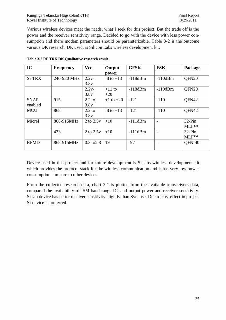
Various wireless devices meet the needs, what I seek for this project. But the trade off is the
power and the receiver sensitivity range. Decided to go with the device with less power con-
sumption and there modem parameters should be paramterizable. Table 3-2 is the outcome
various DK research. DK used, is Silicon Labs wireless development kit.
Table 3-2 RF TRX DK Qualitative research result
IC Frequency Vcc Output
power
GFSK FSK Package
Si-TRX 240-930 MHz 2.2v-
3.8v
-8 to +13 -118dBm -110dBm QFN20
2.2v-
3.8v
+11 to
+20
-118dBm -110dBm QFN20
SNAP
enabled
MCU
915 2.2 to
3.8v
+1 to +20 -121 -110 QFN42
868 2.2 to
3.8v
-8 to +13 -121 -110 QFN42
Micrel 868-915MHz 2 to 2.5v +10 -111dBm - 32-Pin
MLF™
433 2 to 2.5v +10 -111dBm - 32-Pin
MLF™
RFMD 868-915MHz 0.3 to2.8 19 -97 - QFN-40
Device used in this project and for future development is Si-labs wireless development kit
which provides the protocol stack for the wireless communication and it has very low power
consumption compare to other devices.
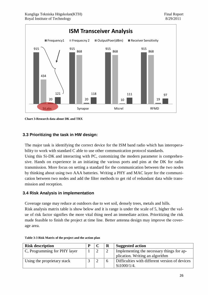
From the collected research data, chart 3-1 is plotted from the available transceivers data,
compared the availability of ISM band range IC, and output power and receiver sensitivity.
Si-lab device has better receiver sensitivity slightly than Synapse. Due to cost effect in project
Si-device is preferred.
Kungliga Tekniska Högskolan(KTH) Final Report
Royal Institute of Technology 8/29/2011
26
Chart 3-Research data about DK and TRX
3.3 Prioritizing the task in HW design:
The major task is identifying the correct device for the ISM band radio which has interopera-
bility to work with standard C able to use other communication protocol standards.
Using this Si-DK and interacting with PC, customizing the modern parameter is comprehen-
sive. Hands on experience in an initiating the various ports and pins at the DK for radio
transmission. More focus on setting a standard for the communication between the two nodes
by thinking about using two AAA batteries. Writing a PHY and MAC layer for the communi-
cation between two nodes and add the filter methods to get rid of redundant data while trans-
mission and reception.
3.4 Risk Analysis in implementation
Coverage range may reduce at outdoors due to wet soil, densely trees, metals and hills.
Risk analysis matrix table is show below and it is range is under the scale of 5, higher the val-
ue of risk factor signifies the more vital thing need an immediate action. Prioritizing the risk
made feasible to finish the project at time line. Better antenna design may improve the cover-
age area.
Table 3-3 Risk Matrix of the project and the action plan
Risk description P C R Suggested action
C, Programming for PHY layer 1 2 2 Implementing the necessary things for ap-
plication. Writing an algorithm
Using the proprietary stack 3 2 6 Difficulties with different version of devices
Si1000/1/4.
915 915 915 915
434
868 868 868
20 20 10 19
121 118 111 97
SiLabs Synapse Micrel RFMD
ISM Transceiver Analysis
Frequency1 Frequecny 2 OutputPoer(dBm) Receiver Sensitivity

Kungliga Tekniska Högskolan(KTH) Final Report
Royal Institute of Technology 8/29/2011
27
Avnet and SiLabs support of the
IC issue
3 3 9 Need a quick response from them regarding
the issue of si1000dk on EZMacPro.
Application Layer programming
for the mesh network
3 3 9 Hands on si1000dk for Application layer
implementation on EZMacPro protocol.
Calculating the radius between the
nodes from field test
1 1 1 Following right instructions and adapting
reliable technology in hardware design
Reliable and robust Implementa-
tion in SI1000DK
2 3 6 Analyzing the result of mesh network im-
plementation and setting up the standard
Not Estimating the time 3 3 9 Estimating the time and identifying the criti-
cal path
Conducting periodic check 1 2 2 Checking at regular interval for the verifica-
tion of work is correct
Antenna design for more gain and
position of antenna for more cov-
erage
3 2 6 Doing simulation of various types of anten-
na for 915Mhz and 434Mhz for the increase
in antenna gain.
P: Probability C: Consequence R: Risk factor (P*C)
3.5 Working with the wireless Development Kit
In this project two type of transmission is tested. One is bi directional, each node act as re-
ceiver till it gets an interrupt from the button. I have written the C code for initializing the
radio and setting the required register for the transmission. Three nodes are used in which one
is the main control unit connected to the PC and other two are remote control unit. The one
which is connected to PC is act as receiver and other nodes transmit the data to receiver node
when it gets interrupt from the button.
Other type of radio transmission method is mesh in that used a packet forwarding method.
Determined after the purchase of Si lab development kit there is a limitation in multi-hoping
and packet forwarding, it can perform up to four nodes not more than that. So the device and
protocol standard approximately cover nearly the 4km range due to use of mesh network. But
not the fully function mesh system like self healing mechanism.
One node performs transmit, receive and packet forwarding. If the node is not within the ra-
dius it will automatically forwards the packet to the destination node. I have written the C
code for following methods are tested in the DK .Sensor network nodes collect the informa-
tion from the user or environmental interrupt such as push button and transmit the collected
information to a central location node.
Target Application: Is to track the positioning of the orienteer’s by an each sensor nodes
fixed at check points.
Each check points sensor nodes are enabled with RFID reader. It reads the unique ID from
passive RFID tag printed on the topographical map which is carried out by participants
throughout the course.

Kungliga Tekniska Högskolan(KTH) Final Report
Royal Institute of Technology 8/29/2011
28
Network Topologies:
P2P:
It is a simple wireless network topology point to point is widely used in small network im-
plementation.
Figure 3-1 P2P
Transmitting a data from multiple node to receiver node
Figure 3-2 Multiple node
Star network topology:
It is a complex topology in which one will act as a master and others act as slave node. Master
nodes controls and supervises the entire network.
Figure 3-3 Star network topology
Advantages:
Low power consumption
Disadvantages: Absence of path redun-
dancy and high probability of data loss.
Network size is depends upon the range of
transceiver.

Kungliga Tekniska Högskolan(KTH) Final Report
Royal Institute of Technology 8/29/2011
29
Mesh network
Figure 3-4 Mesh Network
Advantages: of using mesh network
is path redundancy. It increases the
coverage range and self- healing me-
chanism.
Disadvantage: Complex design, all
the nodes in a network should have
Tx/Rx bi-directional module.
Communication medium
Table 3-1 Wireless Communication Band allocation and there features
Name Proprietary
Stack ZigBee Wi-Fi Bluetooth
Standard 802.15.x(4g,4a,
4f,5) 802.15.4 802.11.a.b.g 802.15.1
Application
Monitoring,
control and Au-
tomation
Monitoring and
control
Web, e-mail,
video
Cable re-
placement
System re-
sources
2.6kbps to
128kbps
50kbps to
60kbps >1Mbps >250kbps
Battery life
Depends upon
the network
topology
100 to >1000 1 to 5 1 to 7
Bandwidth 2.6kbps to
128kbps
20 to 250kb/s
(802.15.4,2003)
54 mbps
(802.11g,2003)
3 mbps
(v2.0 +
EDR),
2004)
Maximum
Transmission
Range (m)
1000+ 100+ 100 10
Success me-
trics
Reliability, less
power con-
sumption, re-
dundant , cost
efficient
Reliability, cost
and power
Speed, flexibili-
ty
Cost con-
venience

Kungliga Tekniska Högskolan(KTH) Final Report
Royal Institute of Technology 8/29/2011
30
4. RF range and frequency calculation:
Section 4 explains about the theoretical calculation of RF range. The theoretical data is com-
pared with the real time data. Various factors which affect the RF range are described. Impor-
tance of antenna gain, receiver sensitivity and offset are highlighted.
4.1 Frequency Programming:
Two different ISM band radio frequencies are used in this project, one is 915 MHz and other
one is 434Mhz. Details of formulas used for calculating the receiver sensitivity, radius, range
between the TX and RX are described at Appendix A.
Frequency is programmed for these two ISM bands. For transmission and receiving desired
channel frequency (f carrier) is programmed into radio by using below formula.
Carrier frequency is generated by fraction-N Synthesizer using 10 MHz as reference frequen-
cy and the clock of third order modulator.
and are the real numbers stored in the registers.
For 434 and 915 MHz, values are
Synthesizer output frequency. Feedback loop has integer part N and fractional part F. F is
determined by carrier frequency, frequency offset and frequency deviation.
Effective partition of bands 240-960 Mhz. High band (HB) for hbsel =1 and low band (LB)
for hbsel =0. After selection of the fb (N) fractional component is solved using the below
formula
.
Formula for the theoretical calculation of the transmitted effective isotropic radiation pattern
For a dipole antenna with a gain of 6dBi

Kungliga Tekniska Högskolan(KTH) Final Report
Royal Institute of Technology 8/29/2011
31
Then = 26dBm for 915MHz device
For 434MHz Transceiver = 19dBm
Free space loss for two frequencies 915 and 434 MHz
Distance assumed is 1 miles for both frequencies 434MHz, and for 915
MHz is
Frequency deviation Δf: peak frequency is configured from +0.625 to +320. ΔF is controlled
by register and it is not dependent on carrier frequency. ΔF will remain in an increment of
625 Hz.
4.2 Frequency offset:
Figure 4-1 Frequecny Offset
Figure 4-2 Transmission and reception factors in wireless medium
TX RX
Tx Antenna
Gain Rx Antenna
Gain
Tx Cable Loss
Rx Cable Loss
Tx Power
Rx Signal
Level
Receiver
Distance
Clear Line of sight
No Freznel Zone
ΔF
Fre
quen
cy
Time
ΔF = [8:0]*625Hz
=
;
ΔF = Peak deviation

Kungliga Tekniska Högskolan(KTH) Final Report
Royal Institute of Technology 8/29/2011
32
Radius of the Fresnel zone calculated using this formula, in which d is the link distance in
kilometers, f is the frequency.
Fresnel zone is the area of line sight radio waves can spread out from antenna. This theoretical
calculation I assumed it on flat surface of the earth. Formula to find out the Fresnel zone is
mentioned below.
Hypothetical receiving antenna:
for the frequency 915 and 434 MHz the value of wave-
length is 0.3278 and 0.69
=
= 8.55E-3;
=
=0.038
Figure 4-3 Radius calculation using Fersnel Equation
=
= 18.106m
4.3 Frequency Offset Adjustment:
At DK, AFC (Automatic Frequency Controller) is disable frequency offset adjusted manually
using the registers. It is not possible to have both AFC and offset because due to the register,
it shares the same registers. Both of these functions are implemented using synthesizer local
oscillator frequency. Calibration range of high band is ±160KHz and in low band it is
±80KHz. For negative offset number, two’s complement of the positive offset number is re-
quired.
AFC: is to compensate the frequency difference between the receiver and the transmitter
r
d

Kungliga Tekniska Högskolan(KTH) Final Report
Royal Institute of Technology 8/29/2011
33
4.4 TX data rate generator:
Two data rate is configured for this application. Lowest possible data rates are used for send-
ing the information, just need to send the EPC code from the RFID tag or some other data but
not the audio and video files. 2kbs and 4.2Kbs are selected for this application this leads to
reduction in the usage of power and longer battery life. TX data rate is determined by using
this formula.
Two modulation types are tested for this application one is GFSK and other one is FSK.
GFSK provides the best performance compare to the FSK.
4.5 Multipath Wave propagation
Waves which are travelling from the antenna or radiate from the antenna it try to travel in
multi-path. Wave from antenna is modified by propagation through environment ahead of
reaching to receiver. These waves are received by the antenna at receiver end and they are
distinguished as
Direct waves –line of sight path travels in a line
Reflected waves – Greater than one wavelength in size for the specific frequency in which
wave reflect from smooth surface
Scattered waves – Waves bounces off from the objects in between the rough surface of
transmitter and receiver that are much smaller than a wavelength size.
Diffracted waves- Bending the sharp corners of waves
Waves which are diffracted, scattered or reflected changes in magnitude and phase due to
1. Absorption of wave energy from the reflected surface
2. Phase change due to reflection of waves.
3. Difference in length of path traveled by waves.
Multipath wave arrives from different angles and directions
Radio waves are likely to behave as sound waves and the device which is furthest signal
strength will be weaker. From Friis equation, aspect which weakens the strength of radio sig-
nal received at farthest distance from the transmitter is
. d- is the distance from the
transmitter and receiver, n=2 strength of received radio signal is proportional to square of the
distance separating the transmitter and receiver. Value n is the exponential factor of the envi-
ronment and n= 2 is free space condition.

Kungliga Tekniska Högskolan(KTH) Final Report
Royal Institute of Technology 8/29/2011
34
Radio waves attenuate when passing from the obstacles due to separation distance. Below
mentioned detail is about the common building material. These figures are considered to be a
good approximation and they are not to replace the field testing figures.
Table 4-1 Value of n for various factors [21]
Ambience “n Value”
Free space 2
Retail store 2.2
Grocery store 1.8
Office (Hard walls) 3
Office (Soft walls) 2.6
Remote keyless entry 4
Open field- TX and RX
at 1.5m above ground
2.5
Open office or retail
space
3
Dense office(Cubical) 4
IEEE 802.15.5 standard provides mesh networking to both high rates and low rate personal
area network. Low rate mesh network is built under 802.15.4 MAC, where as for the high rate
mesh network it uses the 802.15.3 MAC. Use of IEEE 802.15.5 is a WPAN (Wireless Person-
al Area Network) and it has two distinctive features they are
Firstly, it covers longer range due to use of Mesh network topology and the second one it de-
fines normal IEEE standards for a mesh sub layer on top existing 802.15.x MAC and PHY
layers.
Mesh Sub
layer IEEE 802.15.5- WPAN mesh
MAC/PHY
layers
Low-rate WPAN High rate WPAN
15.4b
15.4a
PHY
15.4c
CHN
15.4d
JPN
15.4e
MAC
15.4f
RFID
15..4g
SUN
15.3 15.3b 15.3c
60GHz Table 4-2 WPAN mesh and 802.15 family standards.
4.6 Theoretical Calculation of Antenna EIRP
EIRP for different types of antenna is calculated and mentioned in the below table, formula
use to calculate the EIRP is at APPENDIX A
Antenna Frequecny Measured EIRP Description of Antenna
434MHz loop -17.7 switched to -6 dB state, at
max state 0.8 dB higher (saturated)

Kungliga Tekniska Högskolan(KTH) Final Report
Royal Institute of Technology 8/29/2011
35
434MHz ideal l/4 mono-
pole+50 Ohm matched eval
board
0.5
Ideal monopole requires a
big (d> l) perpendicular
ground plane at the antenna's feeding point
434MHz simple l/4 mono-
pole+50 Ohm matched eval
board
-6.5
In this case the antenna is
directly connected to the
eval board output (i.e. with-out big perpendicular
ground) and the antenna axe
is perpendicular to the eval board
434MHz folded dipole -
915MHz loop -15.2
915MHz xloop small -11.2
915MHz xloop big tbd
915MHz ideal l/4 mono-
pole+50 Ohm matched eval
board
-1.4 Ideal monopole requires a
big (d> l) perpendicular
ground plane at the antenna's feeding point
915MHz simple l/4 mono-pole+50 Ohm matched eval
board
-2.5 In this case the antenna is directly connected to the
eval board output (i.e. with-
out big perpendicular
ground) and the antenna axe is perpendicular to the eval
board
915MHz folded dipole -
915 MHz BIFA 2.2

Kungliga Tekniska Högskolan(KTH) Final Report
Royal Institute of Technology 8/29/2011
36
5. Hardware design Description about the hardware used in the project from the SI-DK is mentioned below from
the data sheet, many of the sensors and calibration is not used from the DK. The used circuit
is transceiver part and the future device is in the size of daughter card [11].
Ultra Low Power: 0.9 to 3.6 V Operations
Typical sleep mode current < 0.1 μA; retains state and RAM contents over full supply
range; fast wakeup of < 2 μs
Less than 600 nA with RTC running
Less than 1 μA with RTC running and radio state retained
On-chip dc-dc converter allows operation down to 0.9 V.
Two built-in brown-out detectors cover sleep and active modes
On-Chip Debug
On-chip debug circuitry facilitates full-speed, non-intrusive in-system debug (No emulator
required)
Provides breakpoints, single stepping
Inspect/modify memory and registers
Complete development kit
High-Speed 8051 μC Core
Pipelined instruction architecture; executes 70% of instructions in 1 or 2 system clocks
Up to 25 MIPS throughput with 25 MHz clock
Expanded interrupt handler
Memory
-4352 bytes internal data RAM (256 + 4096)
-64 kB (Si1000/2/4) or 32 kB (Si1001/3/5) Flash; In-system programmable in 1024-byte
sectors—1024 bytes are reserved in the 64 kB devices
Proprietary Transceiver
Frequency range = 240–960 MHz
Sensitivity = –121 dBm
GFSK, modulation
Max output power = +20 dBm +13 dBm.
Data rate = 0.123 to 256 kbps
TX and RX 64 byte FIFOs
Digital Peripherals
-19 or 16 port I/O plus 3 GPIO pins; Hardware enhanced UART, SPI, and I2C serial ports
available concurrently
-Low power 32-bit Smart Clock
-Four general purpose 16-bit counter/timers; six channel programmable counter array
(PCA)
Package
-42-pin QFN (5 x 7 mm)
Temperature Range: –40 to +85 °C

Kungliga Tekniska Högskolan(KTH) Final Report
Royal Institute of Technology 8/29/2011
37
This is the general overview of the DK and this can be used for various wireless applications
but the target application is for tracking the positioning of the orienteer.
Figure 5-1 General HW Si-DK diagram
5.1 Functional Block diagram of the hardware device:
Figure 5-2 Functional HW block Diagram
Transceiver maximum output power is +20dBm and other device are +13dBm with very low
receiver sensitivity range is -121dBm. Si-DK has the additional features as antenna diversity
and maximum frequency hopping is 4 nodes contrast to packet forwarding. Antenna diversity
can be enabled by slight modification on the existing PCB layout. DK has feature to support
antenna diversity by enabling the register setting using register calculator. Frequency cover-
ISM RADIO
TRX
IC
ANALOG
PERIPHERALS
DIGITAL I/O
ISP FLASH 8051 MCU
(25 MIPS) SRAM
INTERRUPTS DEBUG
CIRCUITRY
POR WDT
Si-1000 DK C8051
Mixed-Signal MCU
RFID Reader
Antenna
Interrupt

Kungliga Tekniska Högskolan(KTH) Final Report
Royal Institute of Technology 8/29/2011
38
age range of this device in general is from 240-960MHz but used frequencies are ISM band in
156 Hz and 312 Hz steps allow precise tuning control. Other features used in the project ap-
plication are low battery detector, automatic wake-up timer, 64 byte TX/RX FIFO’s automatic
handling, and permeable detection reduces the overall current consumption. TRX has the high
performance ADC and DSP based modem used for the demodulation, filtering and packet
handling. Exact modulation, reduced spectral spreading is ensured by using the direct digital
transmit modulation and automatic PA power ramping. Entire power is compliance with glob-
al regulations including FCC, ETSI, ARIB, and 802.15.4d.
This picture is internal architecture of the entire hardware device some of the ports and pins
are needed for this app.
Figure 5-3 SI-DK HW Block diagram [11]
Type of modes used at HW device is master mode, multiple master mode, slave and master
mode. Single master with multiple master mode are feasible by changing the code of library.
Two modes are explained below which is been used and implemented in this project.
4-wire single-master mode is active by enabling NSSMD1 (SPI0CN.3) = 1, at code library.
In this mode, output pin is NSS and can be used as a slave for SPI device. Output value is
controlled by changing the code and as NSSMD0 (SPI0CN.2)

Kungliga Tekniska Högskolan(KTH) Final Report
Royal Institute of Technology 8/29/2011
39
Figure 5-4 is hardware layout of the direct tie method in which TX and Rx are tied in contrast
to switch method Si labs microcontroller c51 is used in the DK.
Figure 5-4 RX/TX Direct tie HW
Second mode is master and slave method with 2 wire signal as master and 3-wire signal as
slave mode is seen below at the connection diagram.
Figure 5-5 RX/TX Direct tie HW
5.2 Network Protocol used:
Network communication protocol between the nodes is standard structured software stack
designed to ensure required data reaches to the destination with minimal loss of packets.
Followed standard structure of the communication protocol is suggested by Open System In-
terconnection (OSI) reference model. OSI has seven individual layers. Not all layers need to
be implemented in certain applications. In this application of small embedded wireless sensor
three layers of OSI standards are only implemented [10].ZigBee stacks reach memory re-
MISO
MOSI
SCK
MISO Slave
MOSI Device
SCK
Master
Device 1
NSS MISO
MOSI
SCK
GPIO
GPIO MISO
MOSI
SCK
NSS
Master
Device 1
Master
Device 2

Kungliga Tekniska Högskolan(KTH) Final Report
Royal Institute of Technology 8/29/2011
40
quirements up to 128k and the stacks used in my designed application for Orienteering may
only reach 10k it is a proprietary based stacks. Modem parameters are set for the automatic
routing to reach within shortest distance to MCU.
Proprietary protocol EZMacPro software modules:
SiLabs implementation provides the common layers and the higher application layer is de-
signed by me for the best optimized Orienteering application. Physical and data link layers
are implemented using the proprietary software and the application layer and its API are writ-
ten by me.
Figure 5-6 Protocol Implemented Layers
FCC5 requirement for frequency hopping systems operates in 902-928MHz band, if +20 db
bandwidth of hopping channel is less than 250 kHz. Maximum allowed hopping channel is
500 KHz to the +20 db bandwidth. (ref)
In my application system where output power can be high without the need to FCC regula-
tions because it compliance towards ETSI6 regulations in Europe. (Mention the regulations
that meet)
Proprietary software stack supports up to four channels of frequency hopping to increase the
robustness of communication.
Features of the proprietary software
It supports wide range of addressing mode, packet-forwarding features while implementing an
advanced frequency search, packet filtering and collision detection with built in acknowledg-
ment. Wireless communication software module for embedded systems
It transmits and receive data in short packet via RF link in the ISM band and it is exclusively
used for embedded application because no part of MAC engine runs in foreground loop.
5 Federal Communications commission’s, as amended by the Telecommunications Act of 1996 (amendment to
47 U.S.C. §151) it is the FCC's mission to "make available so far as possible, to all the people of the United States, without discrimination on the basis of race, color, religion, national origin, or sex, rapid, efficient, Nation-
wide, and world-wide wire and radio communication services with adequate facilities at reasonable charges.
6 ETSI standardizing is for Low Power Radio, Short Range Device, GSM cell phone system and the TETRA
professional mobile radio system. Significant ETSI standardization bodies include TISPAN (for fixed networks
and Internet convergence) and M2M (for machine-to-machine communications). ETSI inspired the creation of,
and is a partner in 3GPP.
Application
Data link layer
Physcial layer
Lower Layer
UpperLayer

Kungliga Tekniska Högskolan(KTH) Final Report
Royal Institute of Technology 8/29/2011
41
Proprietary software is tested as peer to peer network and star network in Orienteering appli-
cation.
Proprietary software is the proprietary stack used for one of the mesh network communication
in this project. It is enabled with more addressing modes, collision detections and error detec-
tion. It has two ISR (interrupt service routines). It utilizes the resources of the proprietary
software RF IC to minimize CPU overhead.
Proprietary stack runs in the background on the main MCU
PHY layer: It provides the interface between physical radio channel and MAC sub layers
(802.15.4)
TX and RX timing
Timing of transmitter and receiver modem initial state is transition from standby mode to TX
and RX mode through the built in sequencer. Desired mode is programmer as idle to transmit
or receiver after that it will go sleep state. Internal sequencer act in changing the current.
Voltage controlled oscillator automatically the frequency change. PLL Ts- settling time de-
fault settling for the Si dk board is 100µs. Total of time required for PLL To, CAL and T s is
200µs. (PLL, CAL is skipped to increase the response time).
XTAL Settling
time PLL T
o
PLL T
s
PR
E P
A
RA
MP
PR
E
PR
AM
P U
P
TX packet
PA
RA
MP
D
OW
N
Figure 5-7 Transmitter timinings [6]
Receiver mode timing: Rx
XTAL Settling time
PLL T
o
PLL T
s
RX packet
Figure 5-8 Receiver packet timings [6]
Proprietary protocol stack is mentioned below it has physical, MAC (Medium access control).
550 µs
550 µs

Kungliga Tekniska Högskolan(KTH) Final Report
Royal Institute of Technology 8/29/2011
42
Figure 5-9 Protocol Architecture layer diagram
Physical layer: Defines a relationship between the hardware device and physical medium. It
initiates the sending and receiving data on carrier.
MAC (Medium Access control) layer: Detect and avoid packet collisions, assist in addressing
mechanism and automatic acknowledgment.
Network layer: end to end packet delivery is taken care by this layer from source to destina-
tion and it enables the packet forwarding feature this feature is limited for four nodes in the
Si-DK ISM radio.
Structure of protocol stack at functional basis:
Figure 5-10 Protocol Architecture Block Diagram
SPI protocol can be used to give external interrupt to the device and this can be used while
integrating RFID reader to the Orienteering device Protocol should be written in function pro-
totype or giving SPI commands from the interrupt of RFID reader to the Si 1000/1004.
Proprietray protocol stack
Physical layer
MAC layer
Application layer
Physical
Network layer
MAC
Orienteering stack –Rest two layers are added.
Application layer controls the communication by making
calls in to the EZMacPro (Proprietary stack)
Application functions call the MAC layer that controls the
interface of Si1000/1004 and the upper application layer
EZMacPro firmware calls the SPI read and writes routines to access the registers and the FIFOs of
si1000/4.

Kungliga Tekniska Högskolan(KTH) Final Report
Royal Institute of Technology 8/29/2011
43
Figure 5-11 Functional Diagram of the stack
Implemented and written the code for the application layer, it has following features
Figure 5-12 Applications enabled and defined on the protocol
5.2.1 Listen Before Talk
LBT (Listen before Talk) is a feature which prevents packet transmission if the channel is
already being used by another to avoid a collision of packets. LBT is a configurable and easi-
ly set to deploy in proprietary protocols and ETSI standards [4].
Frequency Programming
(ISM band 915/434MHz)
TX, RX (Bi-directional)
Four channel is used
Extended Packet Format
Packet Forwading
Low battery detection
Extended header byte and con-trol byte
Packed forwarding
Automatic acknowledgment
MCU
Application layer
Proprietary stack
SPI
Si1000/1004

Kungliga Tekniska Högskolan(KTH) Final Report
Royal Institute of Technology 8/29/2011
44
1. Feature of the LBT and the stack enables the receiver and listens to the channel for
0.5ms. If the channel remains unoccupied by other channel by stack protocol contin-
ues to listen to channel for an additional 4.5ms. If the channel remains free for 5.0ms
period, protocol implemented in this application send the packet. Strength of incoming
signal is determined by using RSSI. In some cases channel becomes busy in last 4.5ms
will jump to additional pseudo random time range and resolution are configurable.
2. If the channel is busy during 0.5ms stack implemented in this protocol check the RSSI
every 1ms until RSSI less than threshold or a total 10ms expires.
Figure 5-13 LBT Flowchart
Initating of LBT (Start)
Listen 0.5ms
No Yes
Channel
is free Lisen 0.5ms Lisen 0.5ms
Yes
Yes
Yes SEND packet Channel
is free
No
1ms
listen
oer
Channel
is free Yes Listen
5ms+Random
No
Channel
is free Yes SEND packet
No
No Max
number CHANNEL BUSY
ERROR
Kungliga Tekniska Högskolan(KTH) Final Report
Royal Institute of Technology 8/29/2011
45
3. Pseudo random time is configured using this formula
TPS = n x LBTI [6:0]
Therefore n is random number from 0 to 15 and LBTI is the listen before talk interval
register. LBTI register is enabled by bit rate (1 to 127 bytes intervals) or fixed inter-
vals as (100us to 12.7ms).
4. RSSI is less than the threshold during the pseudo random and fixed listen time then it
will send the packet. If RSSI level is above threshold the radio stack repeats the listen
before talk mechanism. Maximum limit is set at program and it will wait for a channel
to be free and it will send the packet. LBT is implemented only during packet transfer-
ring not for the acknowledgment.
5.2.2 Packet Forwarding
Packet forwarding function is implemented in the stack for coverage of long distance. Packet
forwarding features in this stack which enables the radio to retransmission of a packet to the
destination node. This makes the node to retransmit of a packet even due to any failure and
packet reach its destination-ID node via multiple nodes.
After using this function at stack and implementing it on orienteering device which increases
the range of radio coverage network.
Radius is the term how many times packets can be retransmitted. For packet forwarding it
should adhere to this
1. Radius field should not be zero
2. Setting the self ID and destination address both are not similar.
Node receives the entire packet and decreases the radius by 1. This function inform to the
callback function to next higher level. Before the packet forward, MAC retransmits the packet
if the radius is zero nodes do not forward the packet. Packet forwarding enables circulating of
packet in network.
Limitation in proprietary stack radius maximum limit is 3.
All packets are identified by the sender ID and the sequence number this helps to avoid re-
transmission of previously forwarded packet with a lower radius. Sender ID is unique and all
nodes store the information about packet sequence number, channel number for the received
packets. (FORWARDED_PACKET_TABLE_SIZE).
Higher software stack interact with this table. Higher software
After packet forwarding it makes a new entry in the forwarding table the entries are Sender
ID, sequence number of the packet. Oldest entry is replaced with new entry.

Kungliga Tekniska Högskolan(KTH) Final Report
Royal Institute of Technology 8/29/2011
46
Destination address is set on the packet forwarding to the only one receiving node so that it
will reach its destination receiver node via multiple nodes.
The entire message is forwarded on the same frequency channel.
When a packet is received state machine decides the next process.
1. After packet sent to receiver node, it enables all the active packet filters and checks the
packet and if it passes it notify the packet reception
2. If the packet reach to different node receiver forwards the packet to destination.
Control Byte (CTRL)
Bit7 Bit6 Bit5 Bit4 Bit3 Bit2 Bit1 Bit0
Seq[7:4] ACK ACKQR RAD[1:0] Table 5-1 Packet Forwarding control byte
5.2.3 Automatic Acknowledgement
Automatic acknowledgment is the feedback from the receiver to the transmitter. Feedback is
about to ensure the packet is transferred to the destination. If the receiver node receives the
packet it is addressed as ACKRQ bit set, this bit generates the acknowledgment message and
sends it back to the transmitter node [4].
Signal strength level indication:
EZRadioPRO radio strength can be determined by RSSI level (receiver signal strength) this
function is used to note the current consumption. Application layer monitor the RSSI level
during packet reception and if the signal strength is higher it will notify. RSSI register holds
the information of the radio signal strength and this allow transmit operation to use less pow-
er.
Table 5-2 Automatic Acknowledgment control byte
Control Byte (CTRL)
Bit7 Bit6 Bit5 Bit4 Bit3 Bit2 Bit1 Bit0
Seq[7:4] ACK ACKQR RAD[1:0]
Permeable Sync ACK
set
CID DID SID PL 0x00 CRC
5.2.4 Low battery detection:
LBD feature in stack which is used to measure the battery life and it will notify if the battery
power is not sufficient enough to drive radio. This protocol stack monitor the power supply
voltage of radio using built in low battery detects circuit.
It measures the provided power supply voltage of a radio as 5bit digital number (VBAT
[4:0]).

Kungliga Tekniska Högskolan(KTH) Final Report
Royal Institute of Technology 8/29/2011
47
Formula used to detect the low power is
Vsupply = (1.675+ VBAT [4:0] x 50mV) +25mv
Threshold voltage is set by using the formula:
Vthreshold = (1.675+ LBDT [4:0] x 50mv) +25mv
If the power supply goes below the threshold, it will call this function
5.2.5 Packet format
Payload varies from 1 to 7 bytes, however the actual packet sent by program is more than this
because it contains preamble, synchronous word, IDs and CRC.
Figure 5-14 Packet Data Format
Header can be configured in a program by enabling the register settings. Four headers for the
four nodes can be configured and Rx will expect the configured header it won’t accept other
packets with invalid header.
Associated request for the header 0x11 sent by node1 it contains 16 bit random address.
Data 0x11 sent from the node it contains battery voltage data and button data fields
11
A1 A2 01 00
APP
type
HW
type Address Assc
Req
2bytes 1byte 1byte 1byte
AA
AA
2D AA AA D4 CID SID DID PL D0
D1 .................. Dn CRC
Payload
CTRL

Kungliga Tekniska Högskolan(KTH) Final Report
Royal Institute of Technology 8/29/2011
48
5.2.6 Receiving data:
During the transmission and receiving process the packets are sent only to the supported
channel. Receiver node repeatedly scans the channel using receiver signal strength. Permeable
is used to synchronize the PLLs for transmission
Figure 5-15 Receiving Data Format
Sync data is the one which initiates the packet reception, header defines the low layer
control and addressing.
Control (CTRL) auto-acknowledgement and packet forwarding
Customer ID (CID) avoids unexpected interactions between systems installed in close
proximity.
Sender ID (SID)—identify transmitting node address
Destination ID (DID)—identifies the receiving node address
Payload length (PL)—number of bytes in the payload (maximum 64 bytes)
AA
AA
2D AA AA D4 CTRL CID SID DID PL D0
D1 .................. Dn CRC
AA
AA
2D AA AA D4 CTRL CID SID DID PL D0
D1 .................. Dn CRC
Permeable Bytes Sync Bytes
TX
RSSI
RX
Scan frequency Chanels F0
F1
F2
F3
Centre
Frequecny
Payload
11
A1 A2 01 B1
Button HW
type
Address Data
2bytes 1byte 1byte 1byte
00
1byte
Battery

Kungliga Tekniska Högskolan(KTH) Final Report
Royal Institute of Technology 8/29/2011
49
5.2.7 Packet configuration:
Name Description Size[Bytes]
AA AA AAAA Preamble Min.4
2D D4 Synchron pattern 2
CTRL Control byte 1
CID Customer ID 1
SID Sender ID 1
DID Destination ID 1
PL Payload length 1
D0...DN Data bytes 0….64
CRC Cyclic Redundancy Code 2 Table 5-3 Packet Configuration [11]
Operating mode of the Radio
Mode
name
Circuit Blocks
Register
status
SPI 32kHz AUX 30MHz
XTAL
PLL PA RX
Shut
down
OFF OFF OFF OFF OFF OFF OFF
Standby
ON
ON OFF OFF OFF OFF OFF OFF
Sleep ON OFF OFF OFF OFF OFF OFF
Sensor ON ON x OFF OFF OFF OFF
Ready ON x ON OFF OFF OFF OFF
Tuning ON x x ON ON OFF OFF
Transmit ON x x ON ON ON OFF
Receive ON x x ON ON OFF ON Table 5-4 Operating mode of the device [11]
Operating mode control:
Transceiver used in this application and project to build mesh application for orien-
teering has four primary states they are shutdown, idle, TX and RX. Shutdown states
completely minimize the current usage by shutting down. Shut down (SDN) pin 20 is
controlled via programming. RX and TX will reach automatically any one of the state
from IDLE mode. Transceiver is integrated with digital regulated supply (LPLDO)
which is internally connected in parallel to digital regulator. Common digital supply
voltage is connected to all digital circuit blocks and digital modem. LPLDO is very
less current consumption and limited current supply capability and can be used only
during IDLE-STANDBY and IDLE-SLEEP modes.

Kungliga Tekniska Högskolan(KTH) Final Report
Royal Institute of Technology 8/29/2011
50
Figure 5-16 Device Working State Diagram
SLEEP MODE:
After MCU and radio are initialized, stack in SLEEP mode. In this mode Radio is
completely switched off and consumes less current (1uA). Radio will wake up 1ms
before transmission or reception. This time is to crystal oscillator to achieve stability.
IDLE MODE:
From sleep mode it will go IDLE mode after the function called in stack it switches to
IDLE mode. In this mode it will wait for the commands, all RF blocks are disable but
crystal oscillator runs in radio. Current consumption of radio 0.6mA, protocol stack
remains in an idle mode unless it receives the information to switch as transmitter or
receiver.
TRANSMIT MODE:
At transmission mode data to be sent to destination address is loaded with appropriate
register all these process done at sleep mode. Once transmit command is sent, radio
will start transmitting and listen before talk will be performed before every packet
transmission.
Automatic acknowledgment wait for the acknowledgment, if the packets arrive within
timeout period, stack goes automatically in next selected state, transmit or receive.
If it arrives after timeout it will show error no acknowledgment and resends the pack-
et.
Two transmitting mode is implemented in two methods one is without feedback and
other one is feedback. Later one consumes more power than feedback features.
SHUTDOWN
IDLE
RX TX

Kungliga Tekniska Högskolan(KTH) Final Report
Royal Institute of Technology 8/29/2011
51
If one channel is received the packet from transmitter node it won’t wait for feedback.
In other feature is acknowledgment from the receiver node. While during the transmis-
sion if the node doesn’t receive the acknowledgment it will retransmits the packet it
used more current compare to no feedback features.
Receive Mode:
From Idle mode it will give to receive mode, protocol stack search for frequency set
(915/434MHz) for a valid data transmission. If a valid data packet has been received
and it checks all the error detection, address filter, then MAC switch to power saving
mode and wait for upper layer to read the data from buffer. Once the data has been
read software goes into any one of the selection mode idle, receive or sleep.
5.2.8 Packet Forwarding
Packet forwarding feature is used to retransmit the data for a long distance so that I
will cover the wide range. For each packet forwarding it decreases the radius by 1 and
performs the listen before talk. It will check for the free availability of a channel for
sending the packet. Node repeats the listen before talk till retry time declared in soft-
ware stack. If node fails to forward the packet, it will repeat to the maximum number
defined in the stack then it will retry and go back automatically to receiver state.
5.2.9 Packet Filtering
Packet filtering works in real time operation. When the packet header is received, filter
check the header bytes, if any bytes are corrupted on header receiving packet will be
stopped. This feature helps to prevent or ignore the unexpected invalid at an early
stage itself. After the abortion reception it will keep on searching for valid packets.
Real time packet filtering increase the performance of a networking system by ignor-
ing invalid packets during the process and saves process power.
Customer ID Filter:
CID is a unique ID and this avoids the interrupted interaction between different sys-
tems. It transmits after permeable and synchron pattern. Networking reception system
can recognize the packet if it is coming from right device or else it will cancel the re-
ception for invalid CID.
Sender ID Filter:
It will filter the incoming packet data by verifying the sender ID field at the receiver
header packet. Sender ID field is enabled as registers and it only accepts the packets
from only specific nodes or group of nodes
Sender ID filter registration at application layer

Kungliga Tekniska Högskolan(KTH) Final Report
Royal Institute of Technology 8/29/2011
52
SMSK 0xFF. SMSK is a register used to mask the bits. Packets will pass the filter if
SFLT & SMSK ==SID & SMSK
Destination Filter:
This filter consists of three address filters and all these address are tested by received
packet. They are self address filter, multicast address filter and broadcast address fil-
ter.
Self Address Filter:
Self address (SFID) is also a unique ID for a node. Each node has the unique SFID
and this identified as SFID. It passes only to those packets whose DID field in the
header equals SFID will pass the self address filter.
Figure 5-17 Packet Filtering method
AA
AA
2D AA AA D4 CTRL CID SID DID PL D0
D1 .................. Dn CRC
Payload
CID Filter
Broadcast filter
Packet length fitler
Sender Filter
Multicast Filter
Self Address filter
CID
PLMAX
MCR
SFID
MCA
A/nM
SFLT, SMSK
CRC
Filter
Packet
CFEN
SFEN
PREN
DFEN
MCFEN
PLFEN

Kungliga Tekniska Högskolan(KTH) Final Report
Royal Institute of Technology 8/29/2011
53
Sleep
Wake Up
Idle
frequency
search
Packet
Receive
Packet
Forwarding ACK TX ?
ACK
transmit
SATX
Packet is valid
LBT Error
ACK RX
Error
Waiting for
ACK
Packet TX
Listen before talk
SATX
ACK
received?
RX ACK?
LBTEN
?
Multicast Address Filter:
It verifies whether a packet is from group of nodes and thus the received packet is a
member of group.
Broadcast Address Filter:
It is a special address 0xFF, packets with this address on the DID field only pass the
broadcast filter.
CRC Filter: It performs the cyclic redundancy check on all the received packets in-
cluding the packet header

Kungliga Tekniska Högskolan(KTH) Final Report
Royal Institute of Technology 8/29/2011
54
Figure 5-18 Flowchart of TRX Device at various modes
5.3 Transmission and reception Operations:
This is the simple P2P communication it transmits the data and received by RX. RX is the
multiple receiver nodes it can receive 64 byte packet data it’s enabled with mesh network.
Flow chart: Transmission node
Figure 5-19 Transmit mode
Receiver node
Figure 5-20 Receiver mode
Snippets of code:
void main (void)

Kungliga Tekniska Högskolan(KTH) Final Report Royal Institute of Technology 8/29/2011
55
{
U8 length;
U8 BUFFER_MSPACE payload[7] = {1,2,3,4,5,6,7};
PCA0MD &= ~0x40; // disable F930 watchdog
MCU_Init();
EA = 1; // enable global interrupts
while(1)
{
//if ( PB1 == 0) // PB1 designates reciever
SFID = 1
if (SW2 == 0)
{
while( SW2 == 0 );
LED1 = 0; // LED 1 indicates receiver
//Set Self ID
EZMacPRO_Reg_Write(SFID, 0x01);
EZMacPRO_Receive();
}
if ( PB2 == 0 ) // PB2 designates reciever
SFID = 2
{
while( PB2 == 0 );
//Set Self ID
EZMacPRO_Reg_Write(SFID, 0x02);
while(1)
{
if ( PB2 == 0 )
{
while( PB2 == 0 );
LED2 = 0; // LED 2 indicates
transmitter
EZMacPRO_Reg_Write(DID, 0x01); //Set
Destination ID
EZMacPRO_Reg_Write(PLEN, 7);
length = 7;
EZMacPRO_TxBuf_Write(length, &payload[0]);
//write the packet length and payload to the TX buffer
EZMacPRO_Transmit();
//send the packet
This is SPI initialization
// Init SPI
SPI_CFG = 0x40; // master mode
SPI_CN = 0x00; // 3 wire master mode
SPI_CKR = SPI_CKR_VALUE; // initialize SPI prescaler
SPI_CN |= 0x01; // enable SPI
NSS = 1; // set NSS high

Kungliga Tekniska Högskolan(KTH) Final Report Royal Institute of Technology 8/29/2011
56
5.4 Flow chart of the mesh networking operation:
Normal transmitter and receiver operation code is implemented with standard C and other
implementation is the mesh with the following three operations they are transmitter, receiver
and packet forwarding. Below mentioned flowchart is the mesh enabled features with packet
forwarding to the 4 nodes.
Transmitter node:
Figure 5-21 Transmitter Node
Later the initialization of HW
peripherals of the MCU and the
proprietary stack and the initiali-
zation of TRX IC and it will in-
itialize the function P2P in pro-
gram after that node goes to
sleep mode and wakes up in
every second for the low fre-
quency timer (LFT). LFT is a
part of feature of the stack and
use the wake up timer of the
TRX IC. It is configured in regis-
ter settings. Operation of the Tx
node is show below.
Program: Tx
void vP2P_TxRun()
// Tx node function
{
U16 wWaitCnt;
EZMacPRO_Wake_Up();
// wake up from
Sleep mode
while(EZMacProReg.name.MSR!=EZMAC_PRO_IDLE); // wait
until the stack goes to Idle mode
LED1 = 0;
// blink the LED
EZMacPRO_Reg_Write(DID, 0x01); // set Desti-
nation ID
bPacketLength = 5;
// set packet
length
wPacketCounter++;
// in-
crease packet number
Power up
Intializating TRX
Start LFT Sleep mode
LFT expired?
Stop LFT transmit mode
Transmit data
N Y
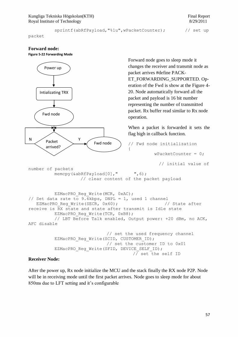
Kungliga Tekniska Högskolan(KTH) Final Report
Royal Institute of Technology 8/29/2011
57
sprintf(abRfPayload,"%1u",wPacketCounter); // set up
packet
Forward node: Figure 5-22 Forwarding Mode
Forward node goes to sleep mode it
changes the receiver and transmit node as
packet arrives #define PACK-
ET_FORWARDING_SUPPORTED. Op-
eration of the Fwd is show at the Figure 4-
20. Node automatically forward all the
packet and payload is 16 bit number
representing the number of transmitted
packet. Rx buffer read similar to Rx node
operation.
When a packet is forwarded it sets the
flag high in callback function.
// Fwd node initialization
{
wPacketCounter = 0;
// initial value of
number of packets
memcpy(&abRfPayload[0]," ",6);
// clear content of the packet payload
EZMacPRO_Reg_Write(MCR, 0xAC);
// Set data rate to 9.6kbps, DNPL = 1, used 1 channel
EZMacPRO_Reg_Write(SECR, 0x60); // State after
receive is RX state and state after transmit is Idle state
EZMacPRO_Reg_Write(TCR, 0xB8);
// LBT Before Talk enabled, Output power: +20 dBm, no ACK,
AFC disable
// set the used frequency channel
EZMacPRO_Reg_Write(SCID, CUSTOMER_ID);
// set the customer ID to 0x01
EZMacPRO_Reg_Write(SFID, DEVICE_SELF_ID);
// set the self ID
Receiver Node: After the power up, Rx node initialize the MCU and the stack finally the RX node P2P. Node
will be in receiving mode until the first packet arrives. Node goes to sleep mode for about
850ms due to LFT setting and it’s configurable
Power up
Intializating TRX
Fwd node
Packet arrived?
Fwd node N Y
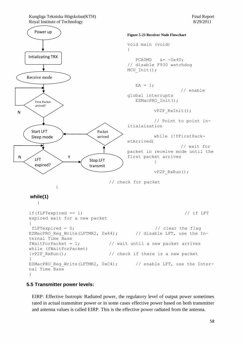
Kungliga Tekniska Högskolan(KTH) Final Report
Royal Institute of Technology 8/29/2011
58
Figure 5-23 Receiver Node Flowchart
void main (void)
{
PCA0MD &= ~0x40;
// disable F930 watchdog
MCU_Init();
EA = 1;
// enable
global interrupts
EZMacPRO_Init();
vP2P_RxInit();
// Point to point in-
itialaization
while (!fFirstPack-
etArrived)
// wait for
packet in receive mode until the
first packet arrives
{
vP2P_RxRun();
// check for packet
}
while(1)
{
if(fLFTexpired == 1) // if LFT
expired wait for a new packet
{
fLFTexpired = 0; // clear the flag
EZMacPRO_Reg_Write(LFTMR2, 0x44); // disable LFT, use the In-
ternal Time Base
fWaitForPacket = 1; // wait until a new packet arrives
while (fWaitForPacket)
{vP2P_RxRun(); // check if there is a new packet
}
EZMacPRO_Reg_Write(LFTMR2, 0xC4); // enable LFT, use the Inter-
nal Time Base
}
5.5 Transmitter power levels:
EIRP: Effective Isotropic Radiated power, the regulatory level of output power sometimes
rated in actual transmitter power or in some cases effective power based on both transmitter
and antenna values is called EIRP. This is the effective power radiated from the antenna.
Intializating TRX
Start LFT Sleep mode
LFT expired?
Stop LFT transmit mode
N Y
Power up
Receive mode
First Packet
arrived?
N
Packet
arrived

Kungliga Tekniska Högskolan(KTH) Final Report
Royal Institute of Technology 8/29/2011
59
It includes any losses for cable, lightning arrestors and any other device placed between
the antenna and transmitter connector. Isotropic gain of antenna is in dBi rating.
Transmitter with 100mW output power is (+20dBm)
Yagi antenna with a 13.5 dBi gain rating.
ETSI Regulatory power –Levels (make a good graph of this table)
Country Frequency Band
(GHz)
Maximum
Transmit Power
EIRP with
TPC(mW)
Maximum
Transmit power
without TPC
(mW)
Austria 5.155.25 200 200
Belgium 5.155.35 120 60
Denmark 5.155.25 50 50
France 5.155.25 200 200
Germany 5.155.25 50 50
Ireland 5.155.25 120 60
Netherland 5.155.25 200 200
Sweden 5.155.25 200 200
Switzerland 5.155.25 200 200
United Kingdom 5.155.35 120 60 Table 5-5 ETSI Regulatory Power Levels [8]
Chart 5-1 Qualitative analysis of ETSI Power Level
0
50
100
150
200
250
ETSI Regualtory level
Frequecny Band (GHz)
Max Tx power EIRP with TPC(mW)
Max Tx power EIRP without TPC(mW)

Kungliga Tekniska Högskolan(KTH) Final Report
Royal Institute of Technology 8/29/2011
60
Chart is plotted from the table 4-9, in x-axis different countries and other hand on y-
axis Power (mW).
5.6 Modulation type used
Two different types of modulation is used and tested with the Hw device they are GFSK
and FSK, GFSK is preferable.
GFSK – Gaussian Frequency Shift keying, it works similar to FSK in addition all data
bits are filtered by Gaussian filter. It diminishes the sharp edges of Tx bits outcome is nar-
row bandwidth [27].
Above diagram represents the modulation spectrum between GFSK and FSK.
GFSK modulation type is set by enabling the register settings at stack. Reason to prefer the
GFSK over FSK is due to robust link. FSK performance is depends upon the crystal
TXCO.
FSK – Frequency Shift keying is a digital frequency modulation method. In which infor-
mation is transmitted as discrete frequency as carrier wave. FSK, changes the frequency of
a signal while transmitting the digital data. Continuous wave signal is transmitted without
modulation of the signal on centre frequency. For sending 0 bit continuous wave signal
frequency is changed and decremented as .
- is centre frequency, is change in frequency called deviation.
For sending 1 bit data it results to increase in normal carrier frequency.

Kungliga Tekniska Högskolan(KTH) Final Report
Royal Institute of Technology 8/29/2011
61
6. Antenna
This section is about the antenna type used in the project and different types of antennas are
simulated for the better performance and there numerical data’s are mentioned below. Two
different types of antenna are used in this project they are RF switch and direct tie method.
RF switch antenna, switch from Tx and Rx. Whereas, direct tie method reduces the switch
timing between Tx and Rx. Antenna type used in this project is whip antenna attached with Si
DK, whip antenna is good at 2d range and at close proximity it provides good coverage where
as in case of 3d not good coverage.
Effects of antenna direction is mention in the below diagram which clearly depicts the role of
antenna direction how vital rather transmitter getting masked.
Whip antenna coverage area. In a flat surface or indoor this is the radiation pattern of an antenna.
Figure 6-1 Radiation Pattern Vertical position
Whip antenna coverage area in horizontal direction.
Figure 6-2Horizontal Position
Diversity antenna is to overcome the multipath fading or multipath distortion. Two identical
antennas can be used to increase receiving sensitivity. Antennas are classified as directional
and Omni-directional. Antenna which transmits and receives in all direction is called Omni-
directional. Directional antenna transmits and receives alone a limited number of vectors.
More about antenna diversity is briefly explained at [6.2]
6.1 Attenuation from trees
Trees are significant source of path loss numerous factors for this cause is wet or dry tree,
deciduous trees, whether the leaves are present or not. Densely covered trees will be a prob-
lem. Attenuation is depends on the distance the signal must penetrate through the trees the
attenuation is of the order of 0.05 dB/m at 200 MHz, 0.1 dB/m at 500 MHz, 0.2 dB/m at 1
GHz, 0.3 dB/m at 2 GHz and 0.4 dB/m at 3 GHz. For lower frequency attenuation is lower
for horizontal polarization that vertical [9].

Kungliga Tekniska Högskolan(KTH) Final Report
Royal Institute of Technology 8/29/2011
62
Multipath distortion is a RF interference that can occur when a radio signal has more than
one path between transmitting and receiving antennas.
Probability for more multipath fading is using near to steel mills, manufacturing area, air-
port, distribution centre, metal walls, Ceilings, shelves or other metallic things in between
receiver and transmitter. Metals reflect the RF signal so it creates multipath condition
Figure 6-3 Multiple path fading.
Antenna starts transmitting means it radiates RF energy in more than one definite di-
rection. This may cause RF signal to move between the transmitting and receiving an-
tenna in the most desired path reflecting or bouncing from metallic and other reflective
surfaces. The phenomenon of reflecting the RF waves will cause reflected wave to
travel farther than the desired direct wave. It may cause delay in receiving the data and
then due to long range transmission route reflected signal loses more RF energy as a
result of reflection or bounce. Finally all the reflected and bounced waves combined
and cause distorting in the desired RF signal.
Changing the location of antenna change these reflections and reduces the chance of
multipath interference. In some scenario, received signals are in an equal strength, yet
delayed in such a manner that they are opposite in polarity, they cancel each other
completely, creating a total absence of received signal by receiver this is known as
multipath null.
6.2 Antenna Diversity
Diversity antenna includes two
antennas that are connected to
RF switch. According to signal
strength receiver switches be-
tween the two antennas on a
regular basis and listens for a
valid signal.
Tx Rx
Obstruction
Time
Time
Signal
Strength
Received Signals Combined Results
Receiver
Circuits
Antenna 1 Antenna 2
Antenna
Switch Control
Circuits
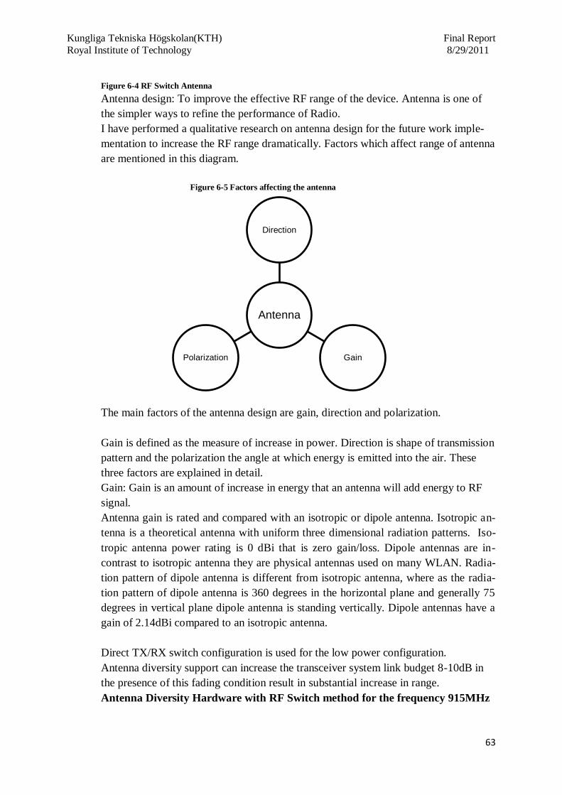
Kungliga Tekniska Högskolan(KTH) Final Report
Royal Institute of Technology 8/29/2011
63
Figure 6-4 RF Switch Antenna
Antenna design: To improve the effective RF range of the device. Antenna is one of
the simpler ways to refine the performance of Radio.
I have performed a qualitative research on antenna design for the future work imple-
mentation to increase the RF range dramatically. Factors which affect range of antenna
are mentioned in this diagram.
Figure 6-5 Factors affecting the antenna
The main factors of the antenna design are gain, direction and polarization.
Gain is defined as the measure of increase in power. Direction is shape of transmission
pattern and the polarization the angle at which energy is emitted into the air. These
three factors are explained in detail.
Gain: Gain is an amount of increase in energy that an antenna will add energy to RF
signal.
Antenna gain is rated and compared with an isotropic or dipole antenna. Isotropic an-
tenna is a theoretical antenna with uniform three dimensional radiation patterns. Iso-
tropic antenna power rating is 0 dBi that is zero gain/loss. Dipole antennas are in-
contrast to isotropic antenna they are physical antennas used on many WLAN. Radia-
tion pattern of dipole antenna is different from isotropic antenna, where as the radia-
tion pattern of dipole antenna is 360 degrees in the horizontal plane and generally 75
degrees in vertical plane dipole antenna is standing vertically. Dipole antennas have a
gain of 2.14dBi compared to an isotropic antenna.
Direct TX/RX switch configuration is used for the low power configuration.
Antenna diversity support can increase the transceiver system link budget 8-10dB in
the presence of this fading condition result in substantial increase in range.
Antenna Diversity Hardware with RF Switch method for the frequency 915MHz
Antenna
Direction
Gain Polarization

Kungliga Tekniska Högskolan(KTH) Final Report
Royal Institute of Technology 8/29/2011
64
Figure 6-6 Antenna Diversity Hardware Design
6.3 RSSI level to qualify antenna selection
Figure 6-7 RSSI Level
Radiation pattern of the general dipole antenna is show at Figure 4-21
Directional Properties: apart from isotropic antenna other antenna has radiation pat-
tern because isotropic antenna is theoretical ideal antenna which radiates equally in all
RSSI1
RSSI2
Antenna
Selection
permeable Sync
Word Data

Kungliga Tekniska Högskolan(KTH) Final Report
Royal Institute of Technology 8/29/2011
65
direction. Beam width is antenna gain coverage area and it’s inversely proportional to
antenna gain. Antenna gain increases and the beam width usually go down.
Omni-Directional Antennas: This kind of antenna is designed to give 360 degree radi-
ation pattern, usually the horizontal plane. Usually this type of antenna is used in cov-
erage in all directions surrounding the antennas on that one plane is required.
Advantages: Long range communications distance. Certain cases gain of the antenna
is very high and.
Drawbacks: Loss of coverage in certain areas. Radiation patterns will be small even a
small motions of the antenna example wind can cause the signal to move away from
the intended target and lose communication and difficult to use Omni-directional an-
tenna in mobile and portable environment.
Polarization: In RF radiations two planes are used they are E and H plane. E is the
electric field defines the orientation of radio waves as they are radiated from the an-
tenna. E is perpendicular Earth’s surface it is knows as vertically polarized. Omni-
directional antenna is vertically polarized antenna.
The horizontal polarized or linear antennas electric fields are parallel to the Earth’s
surface. WLANs rarely use horizontally polarized antennas apart from certain out-
doors, P2P system.
The parameter strictly prohibited is the transmitting power that is permitted from a
WLAN radio transmitter.
6.4 Wave Equation for the future antenna design for better performance
The waves radiated from the antenna obey the Maxwell equation.
Under the assumption of uniform isotropic antenna the equation 1 and 2 will be
With electrical charges
Wave equations are difficult to solve in general, because of the presence of the terms with
current and charge. It is easier to use the magnetic vector potential and the electric scalar
potential.
Magnetic vector potential is , the wave equation for the electrical scalar poten-
tial is

Kungliga Tekniska Högskolan(KTH) Final Report
Royal Institute of Technology 8/29/2011
66
Wave equations are inhomogeneous Helmholtz equations is suitable for the region where
currents and charges are not zero.
At large distance expression for the far field is
At sufficient distance from the antenna radiated fields are perpendicular to each other and
direction of propagation. The magnetic field and electric field are in phase and these are
the properties of uniform plane waves.
The main difference with uniform plane wave is
Surface of constant phase are spherical instead of planar and the waves travels in the
radial direction.
Spherical wave resemble a plane wave with ( ).
Figure 6-8 Spherical Wave
Directivity of antenna is measured in terms =
max {D ( }
It gives the measurement of antenna perfor-
mance in the direction of maximum radiation
related to isotropic antenna.
Dipole far field expressions
And the time average pointing vector is

Kungliga Tekniska Högskolan(KTH) Final Report
Royal Institute of Technology 8/29/2011
67
6.5 Radiation patterns:
Figure 6-9 Radiation Pattern of Electric and Magnet Field
6.5.1 What is the purpose of directional antenna?
Directional antenna fitted to the receiver will receive signal from the transmitter which is
aligned in a direction within a vector of good line of sight to the directional properties of the
antenna. Transmitters which are positioned outside the directional vector line of sight it will
be masked from the receiver.
Transmitter with directional antenna radiates its energy in predefined direction rather than
distributing its energy in all direction which cause the reduction in coverage range.
6.5.2 Simulated Antenna Radiation Plot
Antenna radiation plot comes in polar plane plots and E plane plots. E plot provides brief
information but the direction or pattern shape is not as clear from a polar plot. Polar plot is
similar to compass easier to analyze the antenna gain in any given direction.
Linear antenna simulation result:
Simple far field analysis: Linear Dipole
antenna.
This is the simulated result for the dipole an-
tenna for the frequency 434 MHz in the E-H
field and power and other diagram 90 degree
is the position of the antenna.
Radiated power = 5.2593w = 37.2dBm
Radiation Resistance=6.224025
Directivity=1.5151722, Maximum current
=1.3A
X
Z
Electric and magnetic
field
Plane containing the an-
tenna proportional to
Plane perpendicular to
antenna Omni-directional
or isotropic.

Kungliga Tekniska Högskolan(KTH) Final Report
Royal Institute of Technology 8/29/2011
68
Dipole length for one sided is 0.164m and double sided 0.329m
Figure 6-10 Radiation pattern of E and H Power Radiation Pattern
Detailed Analysis of linear dipole antenna
Figure 6-11 434MHz Linear dipole Simulation Result
Due to its length, current flowing in antenna wire
is function of coordinate z. this figure is the simu-
lated linear dipole antenna length for the frequen-
cy-434MHz.
Simulated result of the Scan field and power
Figure 6-12 434MHz Scan field and power

Kungliga Tekniska Högskolan(KTH) Final Report
Royal Institute of Technology 8/29/2011
69
Angle reference:
Figure 6-13 434MHz Angle reference
Calculated value for the 915MHz
Radiated power = 0.6370191 = 28.04dBm
Radiation Resistance=1.2740382 resistance
Directivity=1.503168
Dipole length for one sided is 0.078m and double sided 0.156m
Maximum current =1.3A

Kungliga Tekniska Högskolan(KTH) Final Report
Royal Institute of Technology 8/29/2011
70
7. Field testing and Analysis of the data
First approach to test the prototype is made from functional and performance point of view.
Different types of test are performed at field at various terrain lands at free space, buildings, at
trees and bushes. Each functional blocks area tested while programming and implemented at
the nodes.
Initial phase of testing the TRX with the spectrum analyzer, transmitted the GFSK signal with
the carrier frequency of 915MHz can be seen in the below picture and I am able to generate
the different frequencies by changing the register settings and the output is seen on spectrum
analyzer.
7.1 Testing the hardware device
Analysis of the result
Parameters for setting the spectrum Analyzer
Ref: 20dBm, RBW: 10 KHz, VBW: 30KHZ, SWT 20ms. Centre frequency is at 913MHz
Device position at 100m in closed space even inside the buildings is 100% packet sent there is
no losses in packet. I transferred the data by a button press then I verified the receiving data
via terminal with the baud rate 115200. Till 500m the device output is ideal at free space

Kungliga Tekniska Högskolan(KTH) Final Report
Royal Institute of Technology 8/29/2011
71
when I go beyond 500m, verified the packet loss and after adjusting the direction of Tx anten-
na I tested hardware device is able to receive another additional two Tx packet compare to the
normal one. Below graph x- axis is the number of packet sent and in Y-axis it’s the field test
distance at various distance from 100 to 550meters.
Pie chart which explains about the factors which affected the antenna range, because I am
working on the DK and the antenna came along with is a whip antenna for testing purpose.
Field test of the device is performed at open space free terrain land. These are the factors
which affected the antenna radiation which made 500meter as possible range of coverage.
7.2 Factors affecting the coverage
Various factors are listed below in pie chart by testing the device in normal open environment
and forest terrain lands. Major disturbance is due to highly densely trees and hill area it leads
to multipath and the numbers are not the exact losses it is an approximate assumption and it
may vary while using diversity antenna or dipole.
At 100m 250m 500m 750m
Packet transmitted 10 10 10 10
Packet received 10 10 10 10
Data lost 0 0 0 0
0
2
4
6
8
10
12
Nu
mb
er
of
pac
ket
sen
t
Histogram of Analyzed data
Environmental factors
50%
Hills, Water 20%
Internal Device 10%
Antenna 20%
Factor Affecting the Coverage

Kungliga Tekniska Högskolan(KTH) Final Report
Royal Institute of Technology 8/29/2011
72
Environmental factors are trees, wet trees, highly density tree, metals and any other reflective
materials between the path of transmitter and receiver.
Hills, cliff are the second contributor in diminishing the range of RF, then internal device is-
sues due to improve handling and loading the data and last antenna. Increasing the gain of the
antenna or using diversity antenna for good reception.
Packets received at terminal
Print screen of 64bytes packet received is show below and each bit data can be written
according to the needs using external interrupt or RFID reader for unique identification and
timestamp of the interrupt push button or RFID reader.
7.3 Serial Port Programming Software
Timer has been created from the software and the timestamp of each interrupt is displayed and
analyzed this is interpreted as the competitors timestamp and synchronization of time at every
node.

Kungliga Tekniska Högskolan(KTH) Final Report
Royal Institute of Technology 8/29/2011
73
I have written the Serial port program in C#.NET. Picture shown below is the serial port soft-
ware diagram and the code is attached at APPENDIX
Time stamp can be seen which is the system time and the date from button interrupt. Below
mention diagram in which NFC reader receives the embedded information from the tag stick
behind the map and the output will be the orienteer name, location and other information. This
the output result received while integrated the NFC device this is additional work apart from
thesis objectives.
Timestamp

Kungliga Tekniska Högskolan(KTH) Final Report
Royal Institute of Technology 8/29/2011
74
8. Battery life Estimation
8.1 AA Battery:
8.2 AAA Battery
Life of the SI labs device si1000 is estimated with the minimum supply voltage 1.3v and the
estimated battery life for AAA will last for 7 years. All three possible combination of AAA
battery is estimated with a single, parallel and series.

Kungliga Tekniska Högskolan(KTH) Final Report
Royal Institute of Technology 8/29/2011
75
Simulated results for three different types
of connection of the battery device is seen
in the figure. As single connection, parallel
and serier connection.
Where as in series connection of the battery
it is clear that the life of battery is more
compared to other two connections.
8.3 Continuous Operation (25MIPS) for the AAA Battery:
25 MIPS, 100% CPU
Utilization
Using internal 24.5 MHz
Precision Oscillator

Kungliga Tekniska Högskolan(KTH) Final Report
Royal Institute of Technology 8/29/2011
76
Connection Estimated Ca-
pacity (mAh)
Average Cur-
rent
µA
Self Dis-
charge Cur-
rent
µA
Estimated System
operating times
days
Single 1200.000 5657.226 3.910 6.935
Parallel 2400.000 5657.226 7820 13.870
Series 1200.000 4100.00 3.910 12.410
8.4 Lithium battery AAA: 15 years 19100
Lithium AA: 15 yrs
Coin cell: Single in series. 3.909 years

Kungliga Tekniska Högskolan(KTH) Final Report
Royal Institute of Technology 8/29/2011
77
9. Future work
This section explains about future work and enhancement of a device, improving performance
of a device and integrating RFID reader. Antenna diversity usage will improve coverage dis-
tance area above 500meters. First part of this section is about RFID functional blocks which
plays vital role for reliable functionality and the second one is about antenna diversity.
9.1 RFID reader System level design
HW device enabled with passive RFID tag and reader target frequency is 13.56MHz. Be-
low diagram is a functional element for the RFID reader for the feature design. Main func-
tional blocks are power supply, clock generator and antenna module with π and T match-
ing.
Figure 9-1 Functional Block of RFID reader design
Clock Generator: Preferred clock generator is to go for low frequency with a limit of 125
KHz square wave. Reason for going lower frequency due to power and many peripherals of
the device don’t need a clock including microcontroller.
Antenna Module: 13.56MHz Antenna with pi or t matching
Filtering Module: Purpose of filters is to remove the unwanted and redundant data. It filters
out the required carrier signal from noises and then filtered data is received by antenna.
Microcontroller: C8051 or any other micro controller can be used and chip does not need
any external clock source it is using one of the internal oscillator to generate its clock.
Power supply Clock Generator (Square wave)
Antenna Module
Simple I/O Microcontroller Filtering Module

Kungliga Tekniska Högskolan(KTH) Final Report
Royal Institute of Technology 8/29/2011
78
9.2 Antenna diversity proposal for future use
Antenna diversity is to increase the receiving strength and coverage area of the signal. This is
the hardware diagram for the daughter card radio transceiver can be used for antenna diversity
with different IC from silicon labs si1000/1/2/3/4.
Algorithm for Antenna Diversity:
Antenna mechanism for future use is briefly
explained. Proprietary radio doesn’t rely on the
transmitter and receiver synchronization. It
overcomes the missed packet problem by pe-
riodically switching antennas whether received
signal is below the signal quality (SQ). SQ is
based upon receiver sensitivity, valid signal
threshold and the antenna selection. If the re-
ceiver selects an antenna it will remain it re-
ceivers the entire packet data then it will
switch.
Switching of antenna is frequent enough to catch the packets on one of the antenna rather
being super fast and slow.
Algorithm for measuring the switching of an antenna is based on timer. When it starts goes
to measure signal quality feature.
9.2.1 State diagram of antenna diversity
Figure 9-2 Antenna Diversity State Diagram
This is the algorithm for verifying the signal quality
is the maximum allowed time in part of a given signal is used to select the antenna that is
permeable of packet. N is the number of antennas used by the receiver.
Start RX
Receive Remainder of
packet
Measuring SQ Switching Antenna
SQ<SQth or Timeout
SQ>=SQth

Kungliga Tekniska Högskolan(KTH) Final Report
Royal Institute of Technology 8/29/2011
79
While measuring the signal quality (SQ), function SQ is measured first and it compare with
the SQ threshold if it’s below than the DQ threshold level timer times out then the antenna
switches and measure SQ state restarts. In contrast, SQ level is above the threshold level re-
ceiver stays with the selected antenna because of valid signal indication. Sometimes quality is
lesser than the expected level is due to interruption noise prior to arrival of packet.
Once the valid signal quality indicator is generated first time, radio antenna diversity algo-
rithm verifies with other antenna for higher signal quality indication before selecting the an-
tenna with highest signal quality.
In future focus is on permeable to make as short as possible without any compromise on fast
clock bit recovery to increase the battery life.
PQD – (Permeable Quality Detector) is to determine the quality of a signal. If the PQD indi-
cates as invalid permeable or time out, next antenna is selected and receiver will try again to
find a valid permeable. Suppose the valid permeable is found RSSI value is stored and Rx
switches antennas to stored RSSI on other antenna. Always antenna with strong RSSI is se-
lected. RSSI measurements are fast time saving and shorter permeable.
Figure 9-3 RSSI Selection of Antenna
Start RX
Receive Remainder of packet
Measuring PQ Switching Antenna
PQ<PQth or Timeout
PQ>=PQth
Measuring RSSI_1
Measuring RSSI_2
Switch Antenna
Switching to Highest RSSI Ant

Kungliga Tekniska Högskolan(KTH) Final Report
Royal Institute of Technology 8/29/2011
80
Figure 9-4 Permeability Strength Antenna Detection
Antenna diversity for the future work is to improve the coverage range and signal strength,
PCB design is a proposed solution and not tested in a lab.
BOM- Bill of material for the devices 915MHz and 434MHz is attached with this project
document at APPENDIX E
Start RX
Receive Remainder of
packet
Measuring PQ1 Switching Antenna
PQ<PQth or Timeout
PQ>=PQth
Measuring RSSI_1
Measuring RSSI_2
Switch Antenna
Switching to Highest
RSSI Ant
Measuring PQ2
PQ
2<
PQ
2th
or
Tim
eout
Kungliga Tekniska Högskolan(KTH) Final Report
Royal Institute of Technology 8/29/2011
81
10. Summary
This section is a summary of the entire project work and the milestone achieved. Pro-
posed a solution for the robust and reliable device for orienteering and created the
hardware device creating protocol standards for communication medium. Successfully
I’m able to communication with two nodes and more than three nodes. Successfully,
implemented the protocol standards in the HW device and able to communicate up to
500m with 915MHZ.
Successfully, I accomplished all the tasks in an estimated time by following the itera-
tive project model. What has been achieved in this project is summarized below.
Reached all milestones and tollgates and my entire project works is successful and
meet the needs of the company NEP AB.
Managed the literature studies on Orienteering sports, collected more informa-
tion about the different types of Orienteering, rules and regulation of the sports.
Investigated with Orienteering sports person about the existing technology
used. Gathered more information about different courses of Orienteering for
various age levels.
Investigation on other types of Orienteering performed in and conducted an
analysis and study on existing Orienteering method, using the RFID DIP me-
thod from the SPORTident, and Emit GPS positioning system.
Proposed a robust solution for the hardware design of multi-hop wireless mesh
network. Managed the research on different network topologies like P2P (Peer
to Peer networking), Star network, mesh network, start mesh and tree for the
minimal packet loss in Orienteering application.
Calculate the RF range of Si labs IC at outdoor with four jumps and estimated
the battery life of using SiLabs IC with various types of batteries like AAA,
AA, Lithium batteries and Coin cell.
Status of my progression first, successfully able to communicated with the two
nodes and able to send and received the packets at Si100 DK (Development
Kit). I have contacted the supplier Avnet for the SI1000DK issue in proprietary
protocol EZMacPro. Successfully I’m able to connect DK to the PC. Success-
fully I’m able to transmitted Tx and Received the frequency of 915 MHz and
913 MHz. I have tested the transmitter from the frequency of 913-903Mhz by
fine tuning the oscillator frequency.

Kungliga Tekniska Högskolan(KTH) Final Report
Royal Institute of Technology 8/29/2011
82
Successfully managed to communicate with multiple nodes and able to imple-
ment the mesh network in HW device, completed the field testing and pro-
posed the future work to increase the effective coverage may increase the cov-
erage area
Conclusion
Additionally enhancement for future pointed out some improvements on antenna de-
sign and integration of RFID reader in the Hw device.
Each node performance is scalable and customizable. It can be used with other stan-
dard C code application and network topologies. It is easier to connect to the main
nodes and change the modem parameters. GFSK or FSK modulation are selected de-
pends upon the needs. Estimated the bill of material and enclosed with this document
as hard copy. Successfully I’m Able to send and receive packets from multiple nodes
without any packet loss at the distance of 500 meters with 4.8kbps data rate at open
terrain land. In future this byte data is converted into graphical or other data format to
interact with GUI for the display. This device can be widely used in any other tracking
application in the field of medical, finance, retail, sport, and defense.

Kungliga Tekniska Högskolan(KTH) Final Report
Royal Institute of Technology 8/29/2011
83

Kungliga Tekniska Högskolan(KTH) Final Report
Royal Institute of Technology 8/29/2011
84
APPENDIX A:
FORMULA:
Formula to calculate the receiver power and transmitter power, EIRP and these formulas are
used to estimate theoretical performance of the designed device.
4
2
RXeff GA
120
2
RXRX
ES
RXRX
RXRXeffRXrec GE
GSASP
41204
222
WP
G
sf
s
mc
m
mVE RXSens
RX
RXSens 2
2
1
4801000
10
30
10
dBmP
RXSens
RXSens
WP
1010
dBG
RX
RX
G
24 r
EIRPSRX
m
mVE
WEIRP
E
EIRP
E
EIRPmr
RXSensRXSensRXSens
id
301000
30
4
1202
n
n
nidreal rr
22
2
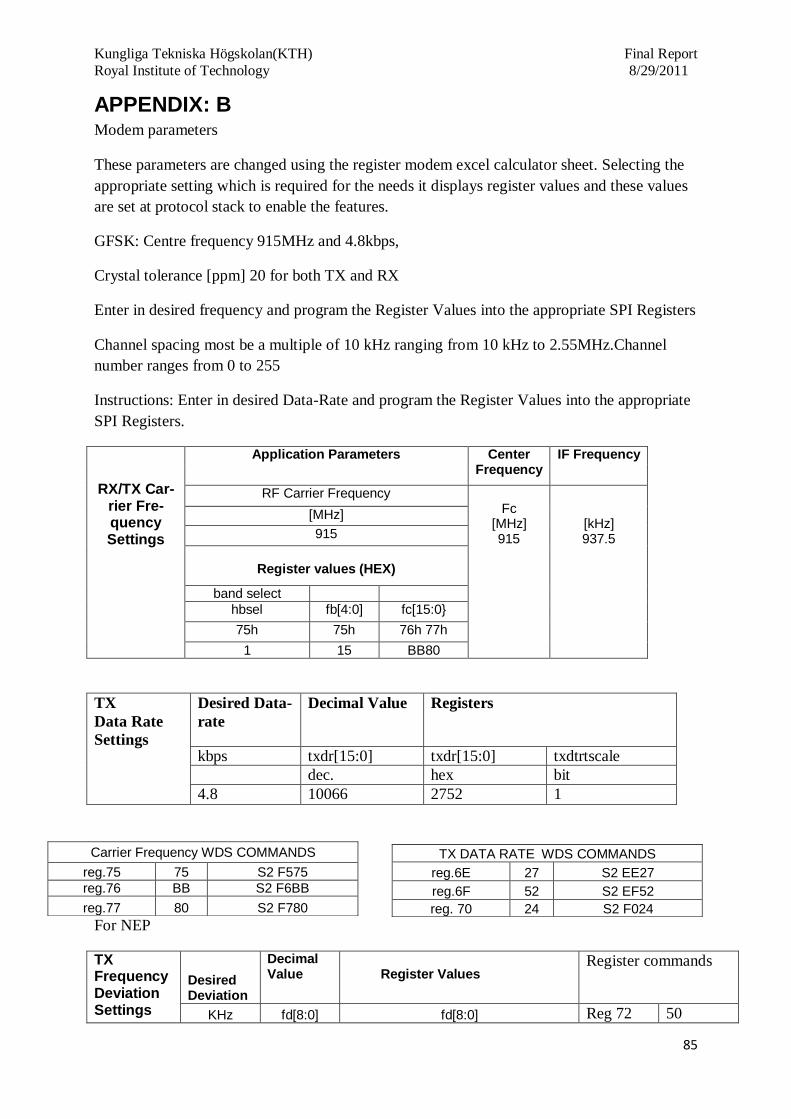
Kungliga Tekniska Högskolan(KTH) Final Report
Royal Institute of Technology 8/29/2011
85
APPENDIX: B Modem parameters
These parameters are changed using the register modem excel calculator sheet. Selecting the
appropriate setting which is required for the needs it displays register values and these values
are set at protocol stack to enable the features.
GFSK: Centre frequency 915MHz and 4.8kbps,
Crystal tolerance [ppm] 20 for both TX and RX
Enter in desired frequency and program the Register Values into the appropriate SPI Registers
Channel spacing most be a multiple of 10 kHz ranging from 10 kHz to 2.55MHz.Channel
number ranges from 0 to 255
Instructions: Enter in desired Data-Rate and program the Register Values into the appropriate
SPI Registers.
RX/TX Car-rier Fre-quency Settings
Application Parameters Center Frequency
IF Frequency
RF Carrier Frequency Fc
[MHz] 915
[kHz] 937.5
[MHz]
915
Register values (HEX)
band select
hbsel fb[4:0] fc[15:0}
75h 75h 76h 77h
1 15 BB80
TX
Data Rate
Settings
Desired Data-
rate
Decimal Value Registers
kbps txdr[15:0] txdr[15:0] txdtrtscale
dec. hex bit
4.8 10066 2752 1
For NEP
TX Frequency Deviation Settings
Desired Deviation
Decimal Value
Register Values
Register commands
KHz fd[8:0] fd[8:0] Reg 72 50
Carrier Frequency WDS COMMANDS
reg.75 75 S2 F575
reg.76 BB S2 F6BB
reg.77 80 S2 F780
TX DATA RATE WDS COMMANDS
reg.6E 27 S2 EE27
reg.6F 52 S2 EF52
reg. 70 24 S2 F024

Kungliga Tekniska Högskolan(KTH) Final Report
Royal Institute of Technology 8/29/2011
86
50
dec. 80
hex 050
Reg.71 2B
For Optional modem performance it’s recommended to set the rxosr at least 6.5 or higher.
GFSK/FSK RX Modem Setting
Application Parameters
Modulation Index
Modulation BW
Channel filter BW -3dB
Est. Freq. Tolerance (SingleSided)
Est. RX sens. BER = 1E-3
Rb Fd AFC enable
H 20.83333333
BWmod [kHz] 104.8
BW [kHz] 115.6
[kHz] 40.5
Input Power [dBm] -113
[kbps] [kHz] 1Dh [6]
4.8 50 1
Register values (HEX)
dec exponent
ch filter data rate
clk recovery
Manchester
AFC BW
Limiter fd[8:0]
BCR Gearsh
ift ndec_exp[2:0]
filset[3:0]
dwn3_bypass
rxosr[10:0]
ncoff[19:0]
crgain[10:0]
enable
1Ch [6:4] 1Ch [3:0]
1Ch [7] 20h, 21h 21h, 22h, 23h
24h, 25h 70h [1] 71h,72h
1Fh[5:0]
2 B 1 271 0346E 007 0 20 03
PH+FIFO MODE:
Packet Structure:
<Permeable> <Sync> <Length> <CRC>
Selected Modulation type is: GFSk
Packet Handler ON
LSB/MSB First MSB
Each byte of the Header, Packet Length and
Data will be sent MSB first
Enable CRC YES
CRC Over Data Only YES CRC will be Calculated Over Data Only
Select CRC TYPE CCIT CRC will be Calculated Over Data Only
Headers in Packet Header 3 & 2 & 1 & 0

Kungliga Tekniska Högskolan(KTH) Final Report
Royal Institute of Technology 8/29/2011
87
Variable Packet Length YES
Sync Word Length Sync word 3 & 2
Selected Preamble Length (in nibbles resolution) - (Decimal value between 0 to 511)
8
Configure sync Word 3 Value 2D
Configure sync Word 2 Value D4
Configure sync Word 1 Value 00
Configure sync Word 0 Value 00
Manchester is DISABLED, the
Actual Number of Preamble bits
will be: 32
The Recommended Pream-
ble Length is 32 (bits) and if
Antenna Diversity is
enabled, 64 (bits).
These values should also be configured into the RX Expected Headers (addresses 0x3F, 0x40,
0x41 & 0x42)
Configure TX Header 3 Value 03
Configure TX Header 2 Value 02
Configure TX Header 1 Value 01
Configure TX Header 0 Value 00
TX Clock configuration 00
RX Configuration:
(This value vary from the using of different daughter cards
RX Header 3 individual bit check mask
Value
FF
RX Header 2 individual bit check mask Value
FF
RX Header 1 individual bit check mask Value
FF

Kungliga Tekniska Högskolan(KTH) Final Report
Royal Institute of Technology 8/29/2011
88
RX Header 0 individual bit check mask
Value
FF
RX Expect Broadcast at Header 3 YES
(Broadcast Packet will
be accepted)
RX Expect Broadcast at Header 2 YES
RX Expect Broadcast at Header 1 YES
RX Expect Broadcast at Header 0 YES
Perform Header 3 Value comparison? NO
Perform Header 2 Value comparison? NO
Perform Header 1 Value comparison? NO
Perform Header 0 Value comparison? NO
Select Preamble Detection Threshold (in nibble resolution)
5
Register address is required to enable in program: Reg. Address
Setting Value (hexa) default ? Information
1C AB These registers are for RX
modem ONLY 1D 40 This is the Default Value after RESET
20 71
These registers are for RX modem ONLY
21 40 22 34 23 6E 24 00 25 07 30 AC 32 F0 33 42
34 08 This is the Default Value after RESET
35 2A This is the Default Value after RESET Relevant for RX settings Only
36 2D This is the Default Value after RESET
37 D4 This is the Default Value after RESET
38 00 This is the Default Value after RESET
39 00 This is the Default Value after RESET
3A 03
Relevant for TX settings Only

Kungliga Tekniska Högskolan(KTH) Final Report
Royal Institute of Technology 8/29/2011
89
3B 02
Relevant for TX settings Only
3C 01
Relevant for TX settings Only
3D 00 This is the Default Value after RESET Relevant for TX settings Only
3E 00 This is the Default Value after RESET
3F 03
Relevant for RX settings Only
40 02
Relevant for RX settings Only
41 01
Relevant for RX settings Only
42 00 This is the Default Value after RESET Relevant for RX settings Only
43 FF This is the Default Value after RESET Relevant for RX settings Only
44 FF This is the Default Value after RESET Relevant for RX settings Only
45 FF This is the Default Value after RESET Relevant for RX settings Only
46 FF This is the Default Value after RESET Relevant for RX settings Only
56 00 This is the Default Value after RESET Relevant for RX settings Only
6E 27
TX DATA RATE 6F 52
70 2C 71 2B 72 50
TX Frequency Deviation
75 75 This is the Default Value after RESET
76 BB This is the Default Value after RESET
Carrier Frequency
77 80 This is the Default Value after RESET

Kungliga Tekniska Högskolan(KTH) Final Report
Royal Institute of Technology 8/29/2011
90
APPENDIX C ITU regions
Region 1
Region 2
Region 3
ISM Band allocation around the globe

Kungliga Tekniska Högskolan(KTH) Final Report
Royal Institute of Technology 8/29/2011
91
APPENDIX D
Sample Orienteering Map, this is the Stockholm Orienteering competition map.
BOM (Bill of material)

Kungliga Tekniska Högskolan(KTH) Final Report
Royal Institute of Technology 8/29/2011
92
APPENDIX E
Serial Port Programming code:
using System.Text; using System.Windows.Forms; namespace SerialCommChat_CS { public partial class Form1 : Form { private System.IO.Ports.SerialPort serialPort = new System.IO.Ports.SerialPort(); public Form1() { InitializeComponent(); } private void btnConnect_Click(object sender, EventArgs e) { if (serialPort.IsOpen) { serialPort.Close(); } try { serialPort.PortName = cbbCOMPorts.Text; serialPort.BaudRate = 115200; serialPort.Parity = System.IO.Ports.Parity.None; serialPort.DataBits = 8; serialPort.StopBits = System.IO.Ports.StopBits.One; // serialPort.Encoding = System.Text.Encoding.Unicode; serialPort.Open(); lblMessage.Text = cbbCOMPorts.Text + " connected."; btnConnect.Enabled = false; btnDisconnect.Enabled = true; } catch (Exception ex) { MessageBox.Show(ex.ToString()); } } private void DataReceived(object sender, Sys-tem.IO.Ports.SerialDataReceivedEventArgs e) { txtDataReceived.BeginInvoke(new myDelegate(updateTextBox)); } public delegate void myDelegate(); public void updateTextBox() { //---for receiving plan ASCII text--- //txtDataReceived.AppendText(serialPort.ReadExisting()); //txtDataReceived.ScrollToCaret(); //---UNICODE work-around--- int bytesToRead = serialPort.BytesToRead; char[] ch = new char[bytesToRead];

Kungliga Tekniska Högskolan(KTH) Final Report
Royal Institute of Technology 8/29/2011
93
int bytesRead = 0; bytesRead = serialPort.Read(ch, 0, bytesToRead); string str = new string(ch, 0, bytesRead); txtDataReceived.AppendText(str); txtDataReceived.ScrollToCaret(); //Console.WriteLine("Data received"); } private void btnDisconnect_Click(object sender, EventArgs e) { try { serialPort.Close(); lblMessage.Text = serialPort.PortName + " disconnected."; btnConnect.Enabled = true; btnDisconnect.Enabled = false; } catch (Exception ex) { MessageBox.Show(ex.ToString()); } } private void btnSend_Click(object sender, EventArgs e) { try { serialPort.Write(txtDataToSend.Text + Environment.NewLine); txtDataReceived.AppendText(">" + txtDataToSend.Text + Environ-ment.NewLine); txtDataReceived.ScrollToCaret(); txtDataToSend.Text = string.Empty; } catch (Exception ex) { MessageBox.Show(ex.ToString()); } } private void Form1_Load(object sender, EventArgs e) { // set the event handler for the DataReceived event serialPort.DataReceived += new System.IO.Ports.SerialDataReceivedEventHandler(DataReceived); // display all the serial port names on the local computer string[] portNames = System.IO.Ports.SerialPort.GetPortNames(); for (int i = 0; i <= portNames.Length - 1; i++) { cbbCOMPorts.Items.Add(portNames[i]); } btnDisconnect.Enabled = false; } private void btnDialNumber_Click(object sender, EventArgs e) { serialPort.Write("ATDT " + txtPhoneNumber.Text + Environment.NewLine); } private void btnAnswerCall_Click(object sender, EventArgs e) {

Kungliga Tekniska Högskolan(KTH) Final Report
Royal Institute of Technology 8/29/2011
94
serialPort.Write("AT*EVA" + Environment.NewLine); } private void cbbCOMPorts_SelectedIndexChanged(object sender, EventArgs e) { } private void Label1_Click(object sender, EventArgs e) { } private void timer1_Tick(object sender, EventArgs e) { listBox1.Items.Add(DateTime.Now.ToLongTimeString() + "," + Date-Time.Now.ToLongDateString()); } private void txtDataReceived_TextChanged(object sender, EventArgs e) { } private void OnTimerEvent(object sender, EventArgs e) { } private void listBox1_SelectedIndexChanged(object sender, EventArgs e) { } } }

Kungliga Tekniska Högskolan(KTH) Final Report
Royal Institute of Technology 8/29/2011
95
REFERENCES
1. Daniel M. Dobkin, ―RFID Handbook: The RF in RFID Passive UHF RFID in Practice‖,
Elsevier, 2008.
2. K. Finkenzeller, ―RFID Handbook: Fundamentals and Applications in Contactless Smart
Cards and Identification‖, John Wiley & Sons; 2 edition, 2003.
3. Si4030/31/32 Register Description Document, Rev.0.1.
4. AN550 Programming Guide document from the Silicon Labs, Rev.0.1 12/09
5. Tan Zhihua, ―The Application of GPS/GIS Navigation and Positioning System in Cross-
Country Orienteering‖, International conference on computer science and software
Engineering. 2008.
6. Si1000 and Si1010 Development Kit user guide, Rev.0.1 1/10.
7. Jianliang Zheng and Myung J.Lee, ―A comprehensive performance study of IEEE
802.15.4‖
8. IEEE P802.15.4/D 18, Draft Standard: Low Rate Wireless Personal Area Networks, Feb.
2003.
9. IEEE 802.11, Part 11: Wireless LAN medium access control (MAC) and physical layer
(PHY) specifications, IEEE, Aug.1999.
10. AN539 EZMacPro Overview document, Rev.0.1 9/10
11. Si1000/1/2/3/4/5 data sheet document, Rev1.0
12. Said A.Elshayeb, Khalid Bin Hasnan and Chua Yik Yen, ―RFID Technology and ZigBee
Networking in Improving Supply Chain Traceability‖
13. Jian Bo, Ma Lianbo and Xu Jiawang, ―Research of the collection System of Logistics
Management Based of RFID&ZigBee Technology‖, 2010 International Conference on
computer Application and System Modelling (ICCASM 2010)
14. Tim Cutler, ―Implementing ZigBee wireless mesh networking‖ July 2005.
15. Lin Zhang, Guangcun Liand Zhigeng Pan,‖ Orienteering Based on System Simulation
Technology‖.Second Workshop on Digital Media and its Application in Museum
&Heritage.

Kungliga Tekniska Högskolan(KTH) Final Report
Royal Institute of Technology 8/29/2011
96
16. Ibrahim Khalid, Mahathir Almashor and Fahim Sufi, ‖Real-time Physiological Condition
and Location Monitoring of Street Orienteering Participants‖.9th
International confer-
ence in Biomedicine,ITAB 2009,Larnaca,Cyprus,5-7 November 2009.
17. Myung Lee and Rui Zhang,” Meshing Wireless Personal Area
Networks: Introducing IEEE 802.15.5.”
18. Texas Instruments®, Application Report SWRA046A, ―ISM-Band and Short Range De-
vice Antennas‖, March 2005.
19. Spread Spectrum Scene, ―Indoor Radio Propagation SSS Online and Pegasus Technolo-
gies‖.
20. Motorola®, Application Note AN2611, ―System Considerations for Short Range RF De-
vices2‖, November 2003
21. ATMEL Range calculation Application note.
22. Advanced Antenna Diversity Mechanism. Qun Shen and Michael Lenzo US pat. No:
5,952,963. September 14, 1999.
23. Network utilizing modified preamble that support antenna diversity. Ronald L. Mahany.
US pat. No: 6,018,555. January 25, 2000.
24. Using Antenna Diversity to Create Highly Robust Radio Links
25. J.Y Wang, H. Min, He ―Design of Logistics-Oriented RFID System, Computer Engineer-
ing and Applications‖, vol 43,no.8,pp 22-33,2007.
26. Event Guideline B: Regional & Local Cross Country Events, Issue 1.0, Effective January
2009 DRAFT.
27. AN415 EZRadioPRO Programming Guide, Rev.0.7 7/10.
![1. Scheme of Work [May 2020] · 1 Cross-Curricular Orienteering Scheme of work & supporting documents for teaching OAA [outdoor adventurous activities] through orienteering at Key](https://img.pdfslide.net/doc/110x75/5f88b743272d9a53432211b0/1-scheme-of-work-may-2020-1-cross-curricular-orienteering-scheme-of-work-.jpg)